Article

Elimination of the Solid Graininess Issue with Different Micro-Pattern Structures at Flexo Printing

Department of Printing Technologies, Faculty of Applied Sciences, Marmara University, Kadikoy, Istanbul 34722, Turkey
*
Author to whom correspondence should be addressed.
Appl. Sci. 2024, 14(18), 8130; https://doi.org/10.3390/app14188130
Submission received: 8 July 2024 / Revised: 16 August 2024 / Accepted: 3 September 2024 / Published: 10 September 2024

Abstract

:

Featured Application

Developed micro-patterns in order to print smooth solid ink laydowns with flexo printing.

Abstract

Flexo printing is a relief printing system, and ink transfers on the solid areas are not transferring well during the printing. That is why graininess is increasing and pinholes are occurring on the solid areas. This is a well-known issue in the flexo printing system. Micro-patterns usually eliminate these pinholes. Using correct micro-patterns allows homogeneous ink laydown and increases solid ink density. Micro-pattern holes behave like gravure cylinders on plate surfaces, and this makes for better ink transfer to the substrate. In this study, a more successful micro-pattern structure than the ones currently used was found by examining the solid ink density (SID) values and ink laydown obtained from the structure by producing eight different micro-pattern structures of 1000 LPI and 1500 LPI (line per inch) pattern screen frequencies with the same polymer structure and type. Densitometric values of solid prints made with the developed micro-patterns were measured. By eliminating the pinholes formed in solid prints and at the screen dot shapes, the ink is distributed more homogeneously without graininess. It has been determined that this results in a more stable measurement of ink density and eliminates the measurement of excess ink and low density.

1. Introduction

A relief printing plate is used as a printing form in flexographic printing. The printing plate is mounted onto the printing cylinder using an adequate substructure with defined height and compressibility [1]. Flexo printing systems are widely used in applications such as plastics, paper, cardboard packaging, and packaging labels [2]. Due to the ability to print a wide variety of functional inks on different substrates, this highly efficient technology has also been successfully applied in various printed electronics applications, such as microscale conductive networks [3]. Figure 1 shows us the flexo printing system: the fountain roller transferring inks to the anilox roller; the anilox roller transferring inks to the printing plate; and the printing plate transferring inks to the substrate.
Computer-to-plate (CTP) technology processes the image areas on the opaque layer on the plate surface and makes them ready for exposure. As micro-patterns begin to be created, a more evenly distributed ink layer begins to be created on the surface. The purpose of the micro-patterns created on the plate is to create various pits in the solid areas on the plate so that printing can be carried out with lower volume aniloxes with less ink consumption. It will provide a high level of performance by using smaller micro-patterns along with CTP and developing technology [4,5].
There are many process parameters that can affect print quality in flexography [6], such as the surface structure of the plate surface [7], anilox cell volume and frequency [8], printing speed, applied pressure, and ink [9].
The correct amount of ink required to transfer to the printing plate is controlled by adjusting the engraved cell parameters. The capacity of ink on an anilox roller is usually stated in cubic centimeters of ink per square meter; this is an estimate of the maximum theoretical ink transfer to the substrate [10].
Various techniques and methods have been developed for the evaluation and characterization of flexographic printing plates according to their performance. For the three types of plates (i.e., rubber, liquid photopolymer, and solid sheet photopolymer plates), the basic principles and methods used in the evaluations are similar. Important properties include volume, surface, and application properties (e.g., resistance to solvents and inks) [1].
Figure 2 shows us flexo printing plates in lateral view. Relief depth affects the printed line width and dot size as it plays a role in the deformation of the plate. For instance, deep relief depth makes it easier to be affected by external impacts. Lower relief depth makes a stronger plate. Relief depth should be balanced by plate thickness in order to correct relief depth and should follow the manufacturer’s recommendations. In recent years, great advances in the development of photopolymer printing plates have increased the quality of flexography, making it a strong competitor for printing processes. However, there are many process parameters that can affect print quality in flexography printing. There is little research on the parametric study of flexography, and this provides the opportunity for further study [6].
One of the most important elements affecting the print quality in flexo printing systems is the choice of plates [11]. The plate is prepared before the real printing starts, while the dot gain is observed via the test printing at the conditions desired to be produced [12]. The dot gain adjustments required for the preparation of the plate are made based on the results of this process, and the plates are prepared. The important thing here is that each printing variable remains fixed so that optimal plates are prepared. By managing how the printing variables affect the printing process, unnecessary waste of time is prevented, and the plates at the right properties are prepared in one sitting. Computer-to-plate imager technology is used to process plates.
Flexography is challenging with gravure printing-related ink transfer achievement. In principle, flexo printing ink transfer directly connects anilox volume; it can make low-volume cell aniloxes printing solids worse than gravure. Micropatterns significantly increase solid ink density in flexo with plastic film substrate. Micro-patterns transferring ink to the solid area better, increasing SID, the characters, lines, and the edge of the solid area can easily result in better ink laydown. Micro-pattern application on the flexographic plate has a higher SID than the non-pattern part, which has also become a block to the quality of the flexographic printing [13]. Micro-patterns also increase ink coverage for white color with transparent plastic film substrates [14]. Mechanical printing settings, press speed, and surface tension of inks also affect ink transfer [15].
The ability of a printing system to reproduce a sharp image with clear details is vital for high-quality reproduction. The geometry of the printed elements, sharpness, and noise of the edges, together with a uniform ink layer, are important indicators of quality production that need to be analyzed. They are directly linked to the reproduction of lines, texts, and dots that are part of every image. Quality parameters of thin elements can be evaluated by measuring line wicking, which makes lines and text blurry or thick [16].
The goal of this research is to print at higher solid ink density and obtain less grainy solids with generated various micro-patterns. Printing conditions were stable, and only micro-patterns were changed. The obtained result will show differences between pattern and non-pattern surface print results.
The significance of this study is to improve the ink laydown and to provide a problem-free structure for the solid areas of the objects, such as text, graphics, barcodes, etc., with narrow web flexography. For instance, if the ink laydown is not sufficient in barcode printing, it may cause problems in use as a result of packaging.

2. Materials and Methods

Higher SID and lower graininess were targeted in this research. To obtain these targets, some parameters have been changed on digital plate-making systems, and then, these different parameters were tested in stable flexographic printing. Then, the test results were measured.
The methodology of this research is as follows:
  • Digital plate-making,
  • Flexographic printing,
  • Measurement process.

2.1. Digital Plate-Making

In this study, various micro-patterns were imaged as controlled on the Cyrel EFX flat top plate with an ESKO CDI imager and processed in DuPont Cyrel Fast thermal plate-making technology. In the printing results obtained with these micro-patterns, the solid ink density and graininess were measured. As a flexography plate, DuPont Cyrel EFX (flat top dot thermal smooth surface plate, which is producible with controlled micro-patterns) was used. The thickness of the plate was 1.14 mm. The durometer of the plate was 76 Shore A. The printing of the plates was carried out in conditions consistent with the TAPPI T402 SP-13 [17]. standards and in one day at the same environment.
Plate-making process specification are as follows:
  • Digital Imager (CtP Device): ESKO CDI Spark 4835 (ESKO, Ghent, Belgium);
  • Resolution: 4000 dpi;
  • Photopolymer: DuPont Cyrel EFX 045 Digital Plate;
  • Plate thickness: 1.14 mm;
  • Plate Exposure UV-A Output: 22 mW/cm2;
  • Line ruling: 150 lpi;
  • Screen angle: 37.5°;
  • Screening type: Circular AM;
  • Micro-pattern line rulings: 1000 lpi, 1500 lpi;
  • Pattern angle: 45°.

2.2. Printing

In these tests performed on the Omet XFlex X4 press (Omet, Lecco, Italy), Flint Group Flexocure Force UV-cured ink cyan color was used during the tests. Cyan was chosen in this test because K is often used for the shadows. Yellow is a color in which we cannot see details. We could use cyan or magenta in the CMYK process color system. Anilox was Harper, screen ruling was 375 L/cm, and a cell volume of 3.1 cm2/m3 was used. Tesa Softprint® Steelmaster open-cell foam tapes were used as plate-mounting tapes. The thickness of the mounting tape is 0.38 mm. Moreover, Tesa 72,022 medium-soft and Tesa 72,026 medium-hard tapes were printed. PVC and PET substrates are used.
Ink type and viscosity, anilox roller, printing pressure, and printing speed were adjusted at the same values in all test prints. All test samples are taken for measuring after printing 100 m (after print setup).
Printing specifications are as follows:
  • Flexo press: Omet XFlex X4
  • Printing Speed: 80 m/min;
  • Flexo ink: Flint Group Flexocure Force UV cyan;
  • UV Curing: UV Lamp, 600 WPI output power (Watts Per Inch);
  • Printing width: 330 mm;
  • Printing length: 419 mm;
  • Anilox line count: 375 L/cm (950 lpi);
  • Anilox cell volume: 3.1 BCM (Billion Cubic Microns);
  • Plate mounting type: Tesa 72,022 medium soft, Tesa 72,026 medium hard, 0.38 mm thickness;
  • Substrates: PVC (polyvinyl chloride) film and PET (polyethylene terephthalate) film. Pre-treatment applied PET surface energy 42 dynes/cm and PVC film surface energy of 46 dynes/cm.
Substrate specifications:
  • PVC: White monomeric, plasticized PVC film. Basis weight 112 g/m2 (ISO 536) [18], caliper 84 μm (ISO 534) [19].
  • PET: Clear PET film. Basis weight 105 g/m2 (ISO 536), caliper 75 μm (ISO 534).
Ink mixture: Tripropylene glycol diacrylate, poropylidynetrimethanol, ethoxylated esters with acrylic acid, 4,4’isopropylidenediphenol, oligomeric reaction products with 1-chloro-2,3-epoxypropane, esters with acrylic acid, 2-propenoic acid, 1,1’-(1,6-hexanediyl) ester, 2-propenoic acid, reaction products with pentaerythritol examethylene diacrylate [20].

2.3. Preparation of Test Plate

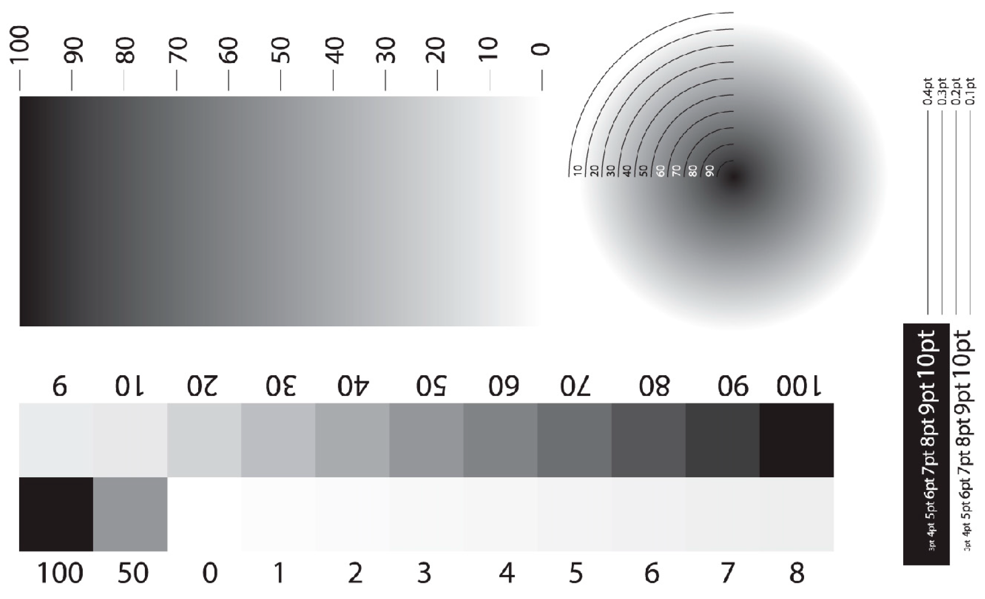
Control strips are formed at 1%, 2%, 3%, 4%, 5%, 10%, 20%, and 30% (to observe the highlights); 40%, 50%, and 60% (to observe the mid-tones); and 70%, 80%, and 90% (to observe the shadows) tonal values. In addition, linear and radial gradients were formed that cross over from 100% to 0%. Printed test images are given in Figure 3.

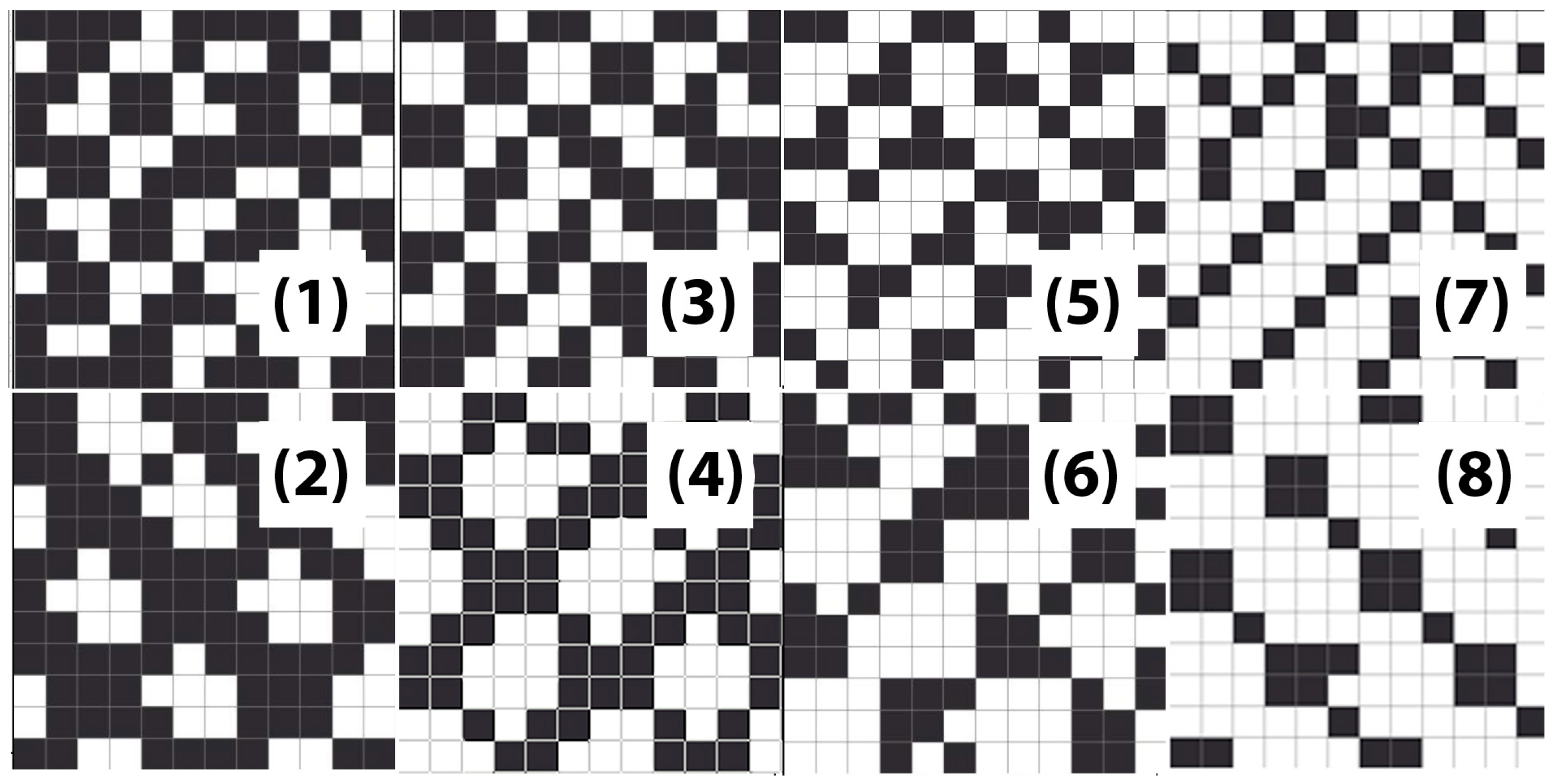
2.4. Designing of Micro-Patterns

Eight different micro-patterns were prepared with micro-pattern-inspired rulings of 1000 lpi and 1500 lpi with angles of 45 degrees. These micro-patterns resolution was 4000 DPI (dots per inch). Pattern size was 7.62 µm, and they were repeated x- and y-coordinates. In this study, the newly developed micro-pattern types are shown in Figure 4.
Patterns were designed as matrices consisting of 12 bits horizontally and vertically. Furthermore, 1 is shown as areas where the laser works, and 0 is shown as areas where the laser does not work. The structure of the matrix is described as a row from top to bottom.
Figure 2 and Table 1 and Table 2 bitmap matrix forms show the shapes of micro-pattern structures that were used for the test. Micro-patterns were produced at an angle of 45°. They were randomly generated at 1500 LPI and 1000 LPI pattern screen frequencies and different tonal values. The target was to increase solid ink density and reduce graininess; micro-patterns that support high ink transfer were preferred. The smoothness in solid ink density and ink laydown is one of the important factors that determine the quality of the appearance of the print.
Pattern   size   ( µ m ) = 2540 4000   p p i × 12   pixel

2.5. Measurements

An X-Rite Exact NGH spectrophotometer was used for SID (solid ink density) measurements. In the measurements, solid ink density and the undesired shadows on the edges of the negative text called trail edge void were also examined. The Peret Flex 3 Pro device was used for evaluation and graininess measurements. This device is a 3D microscope that measures the quality of ink spread on the solid.
Spectrophotometer specifications are as follows:
  • Measurement Geometry: 45°/0° ring illumination optics, ISO 5-4:2009(E) [21].
  • Spectral Range: 400 nm to 700 nm with 10 nm interval
  • Aperture: 2 mm
  • Short-Term Repeatability—Density:
  • +/−0.01 D for CMYK measurements (non-polarized @ 2.0D)
  • +/−0.01 D for CMK measurements (polarized @ 2.0D)
  • +/−0.01 D for Y measurements (polarized @ 1.7D)
  • (Status E or Status T measurements)
Measurement conditions are as follows:
Measurements are made according to the ISO 13655-2009 [22] standard using the M3 settings: illumination D50, observer 2°, density status: ISO E, white base, and polarization filter. Leneta 3NT-35 paper was used as a white background in order to measure. Three samples were taken after each 1000 m and measured on different three points for solid ink density measurements. Average result were revealed and considered.

2.6. SID (Solid Ink Density)

Figure 5 shows us the working principle of the densitometer. Light from a light source was reflected onto the printed substrate. The reflected light was directed to the light sensors inside the device, and the reflected amount was calculated and displayed to the user as a value on the screen. Density was calculated using the formula in Figure 5 [23].
It is known that variables such as plate, ink, printing speed, anilox rollers, substrate materials, and micro-pattern application cause variability in the SID during printing. In order to achieve high SID points, high ink transfer should be managed [24].
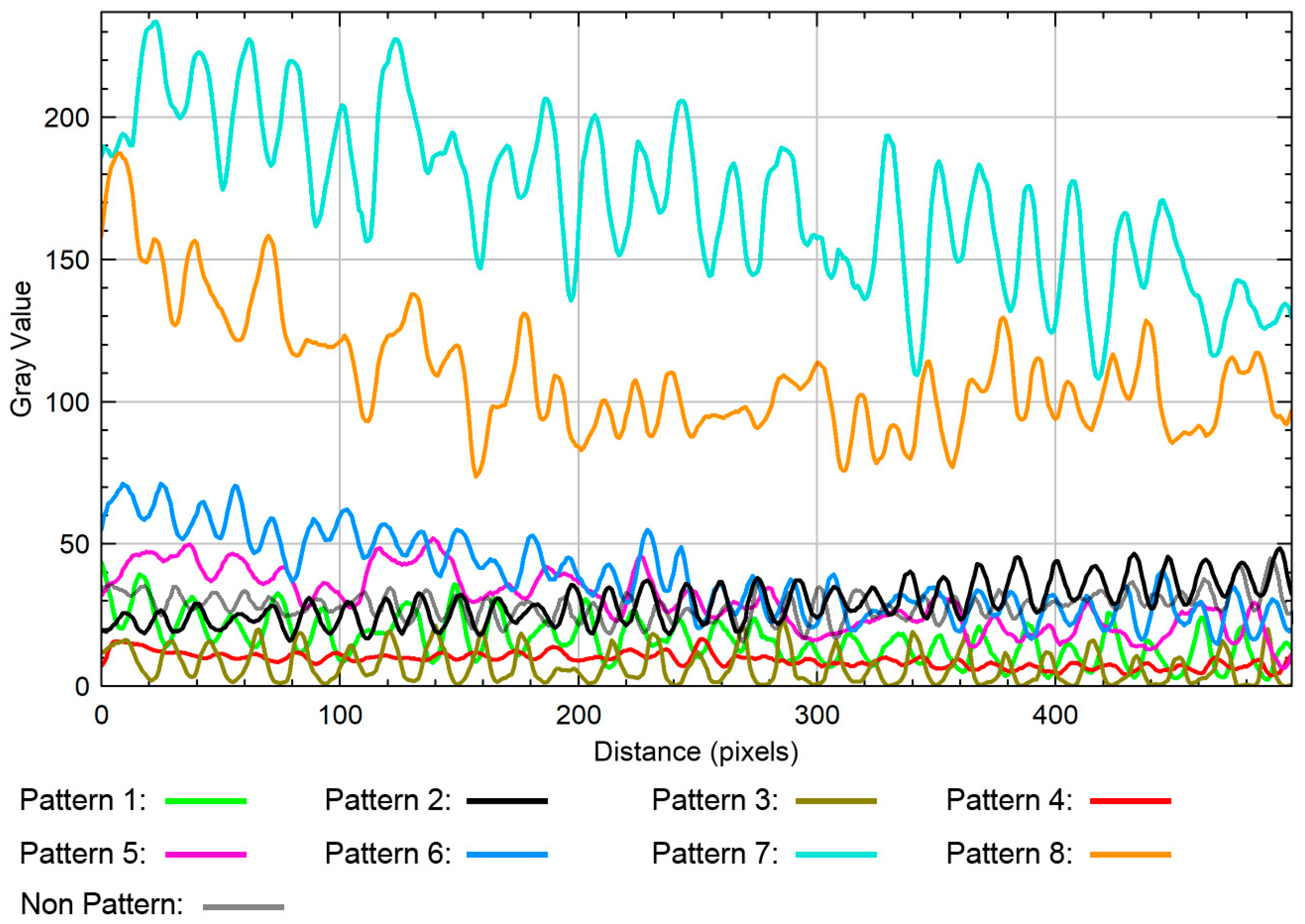
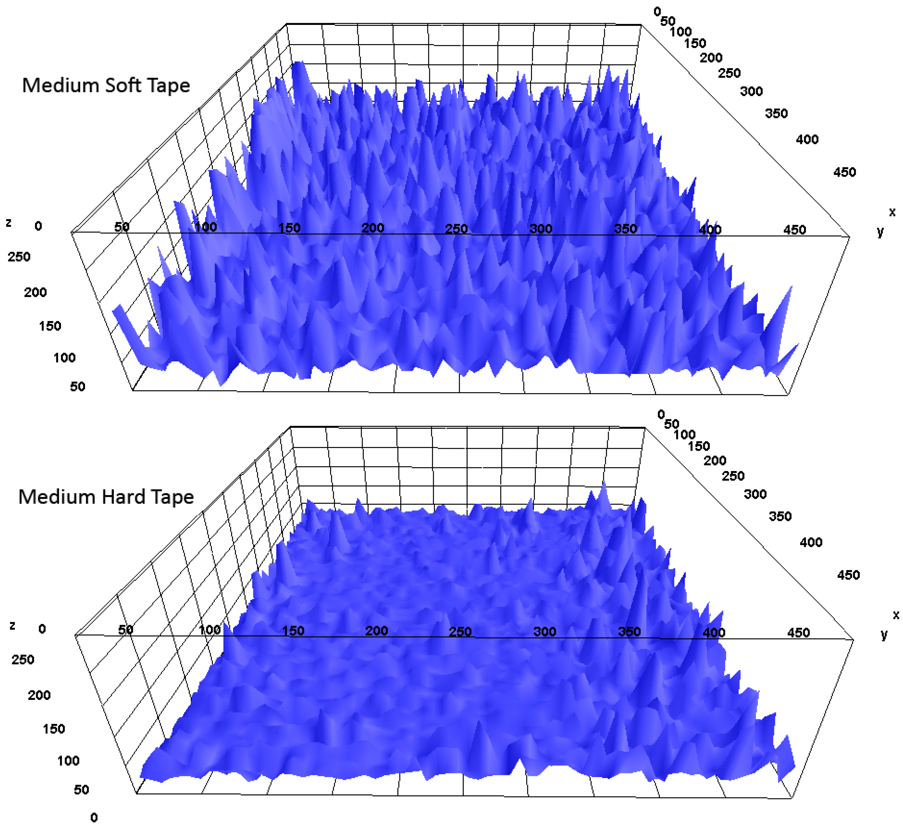
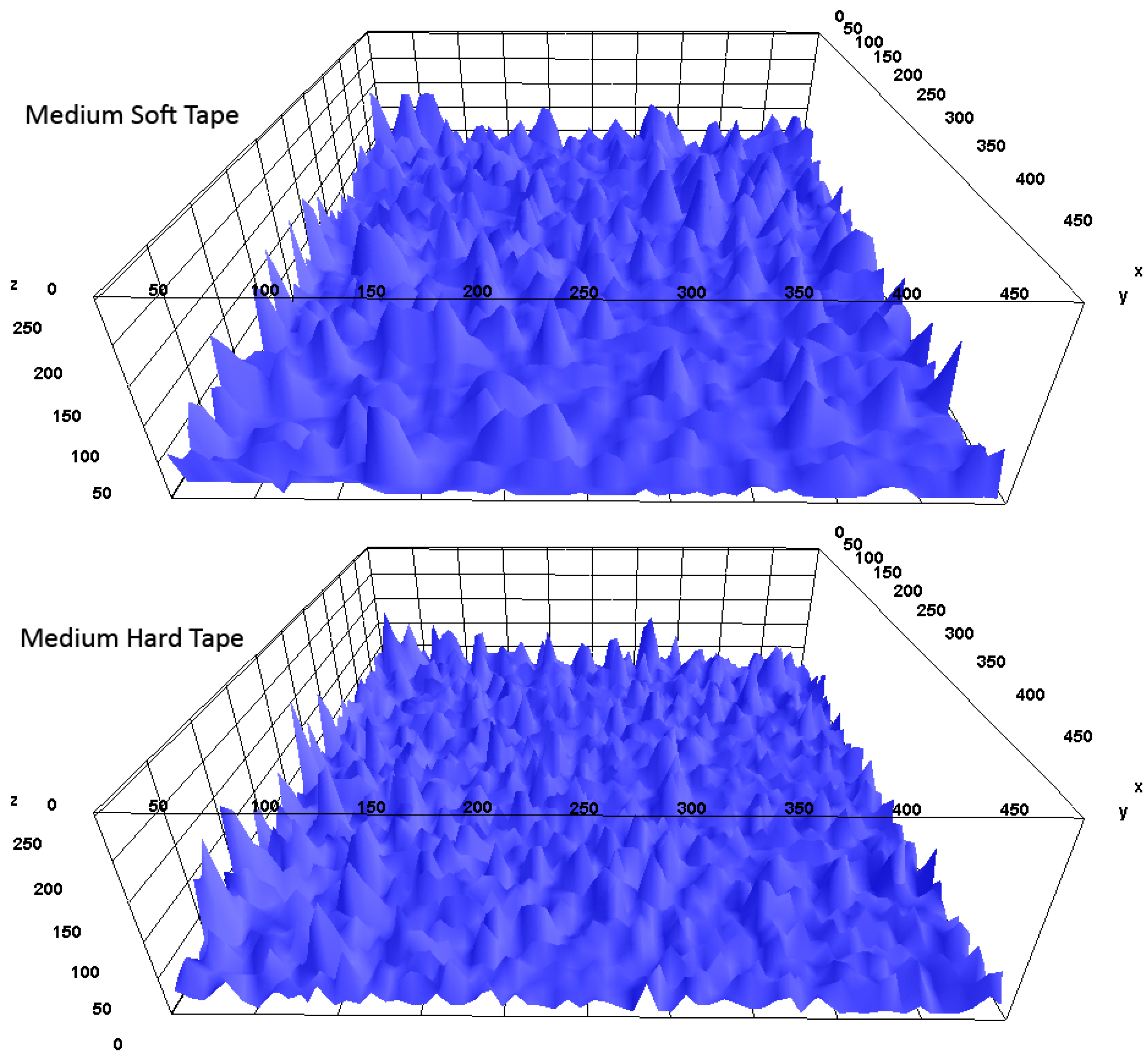
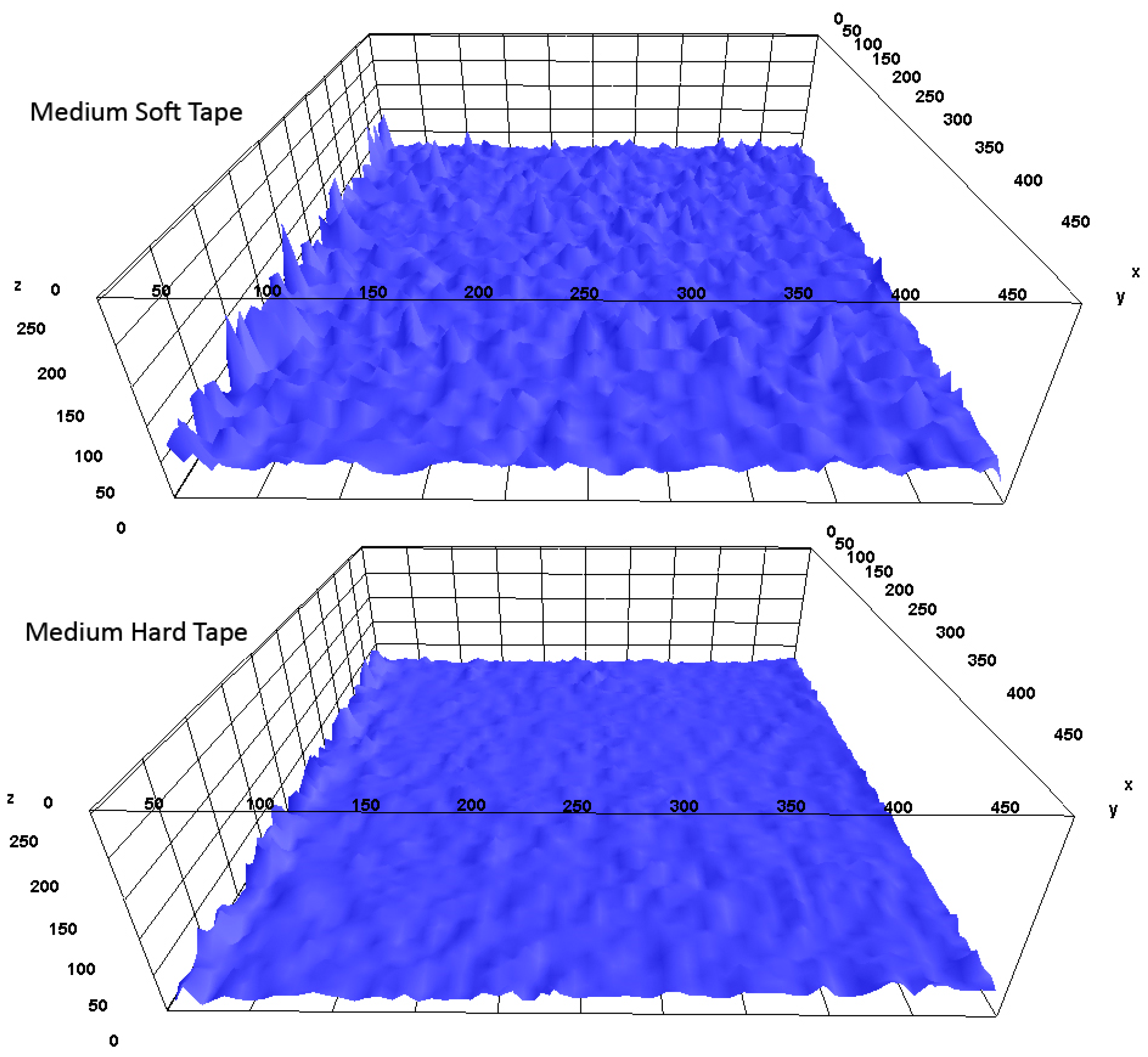
After all patterns are printed, surface graininess was analyzed with the plot profile function. This function shows each micro-pattern graininess intensity with an x-axis and y-axis. Also, all printed pattern results and graininess were analyzed as topographic views with the 3D surface plot method.

3. Results and Discussion

The different behaviors of the different types of micropatterns created on PVC and PET printing substrates are determined by measured values. These determined values are presented below, supported by visuals.
The values obtained as a result of the measurements of eight different micro-patterns created are given in Table 3. Values marked in green are the best results; values marked in orange are the worst result.
According to this table, Pattern 3 with medium-soft tape on PVC printing substrate has a solid ink density higher than other patterns and a non-pattern surface, and the graininess is reduced. In Pattern 4, higher solid ink density is achieved in both PVC and PET printing substrates, and less graininess is achieved compared to the SID values that do not contain micropatterns.
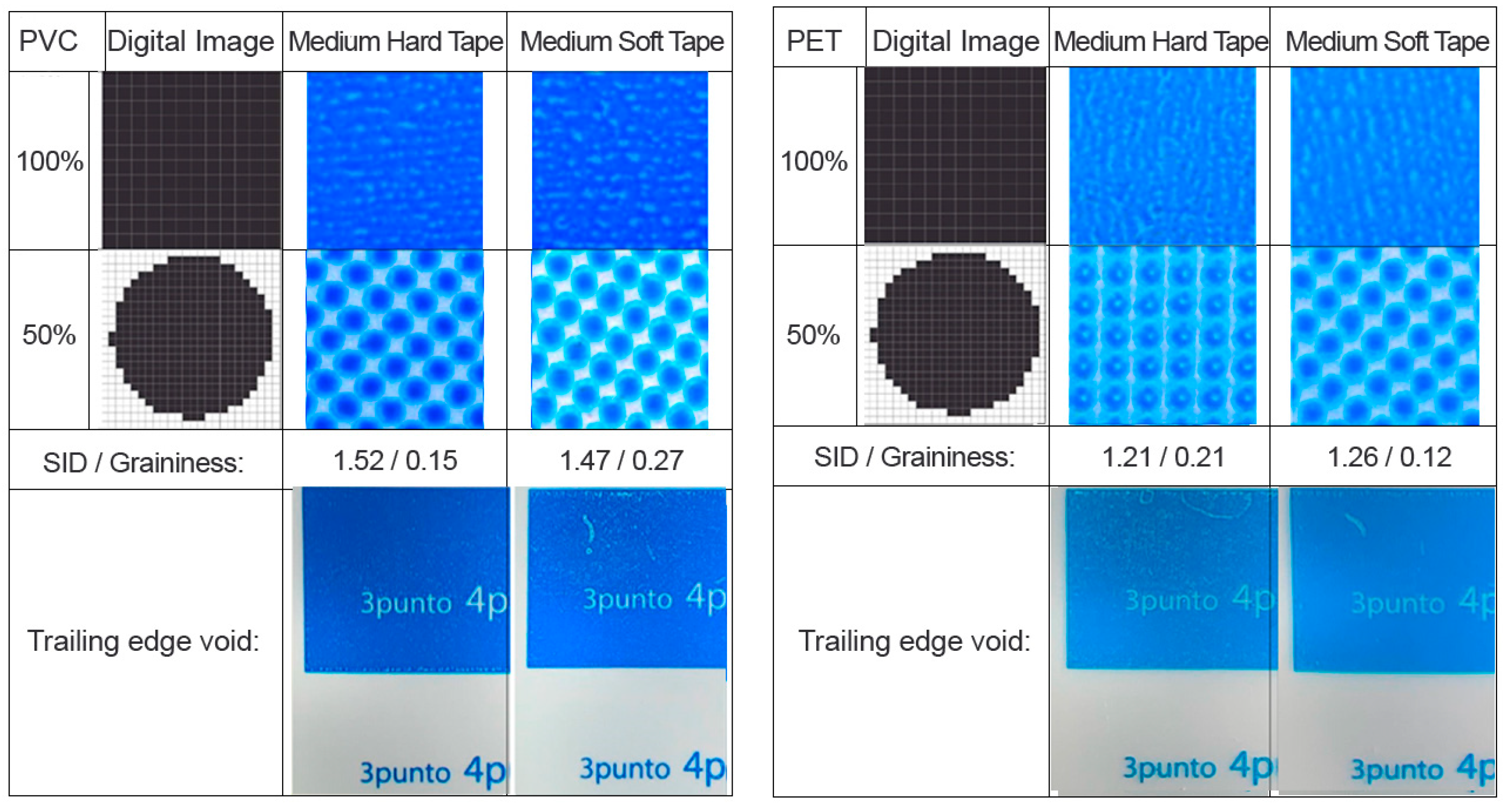
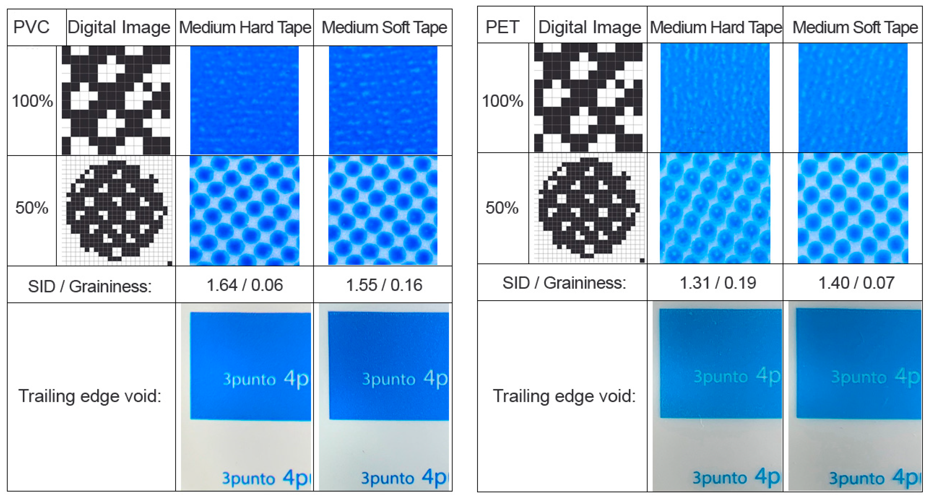
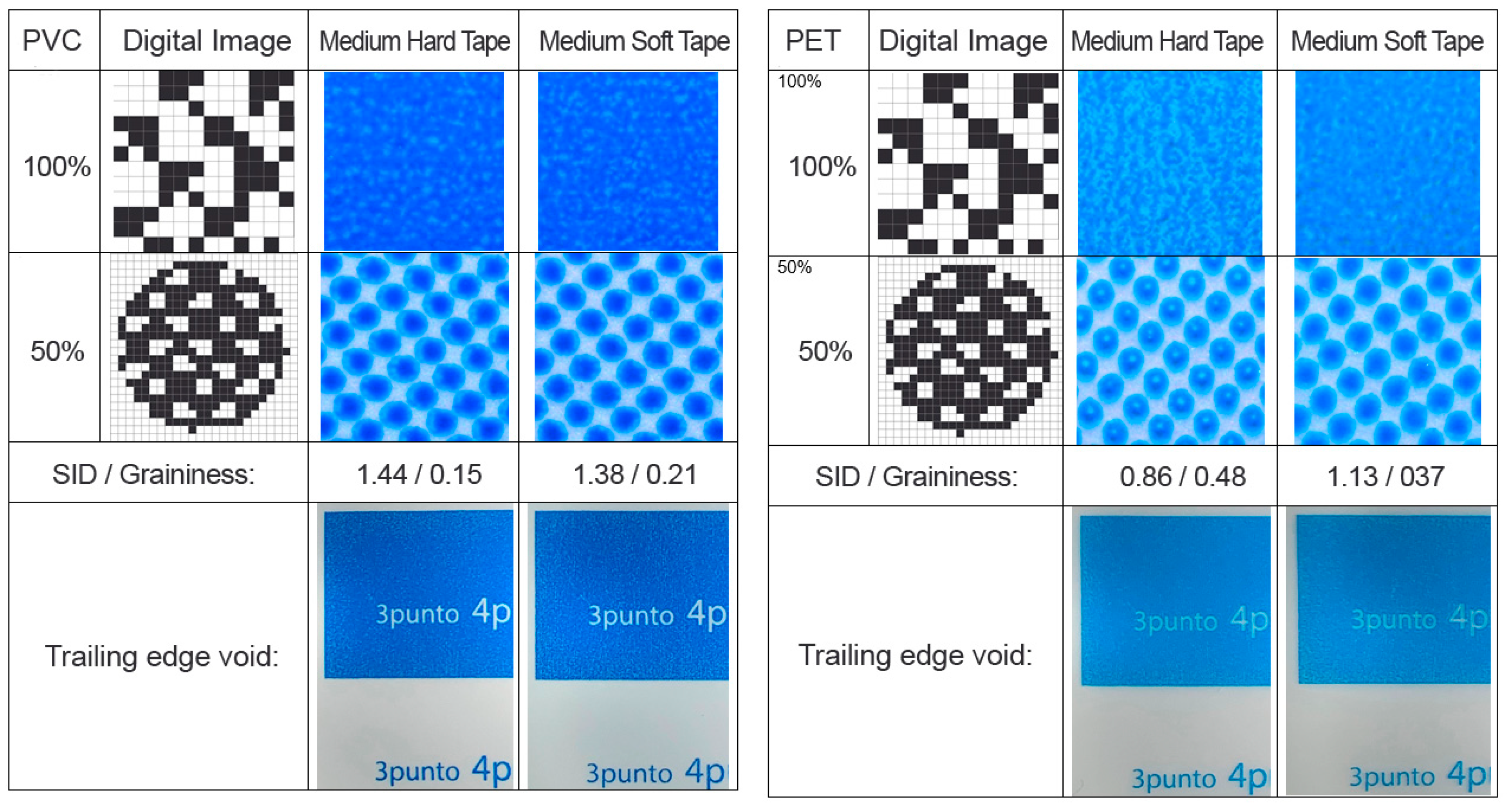
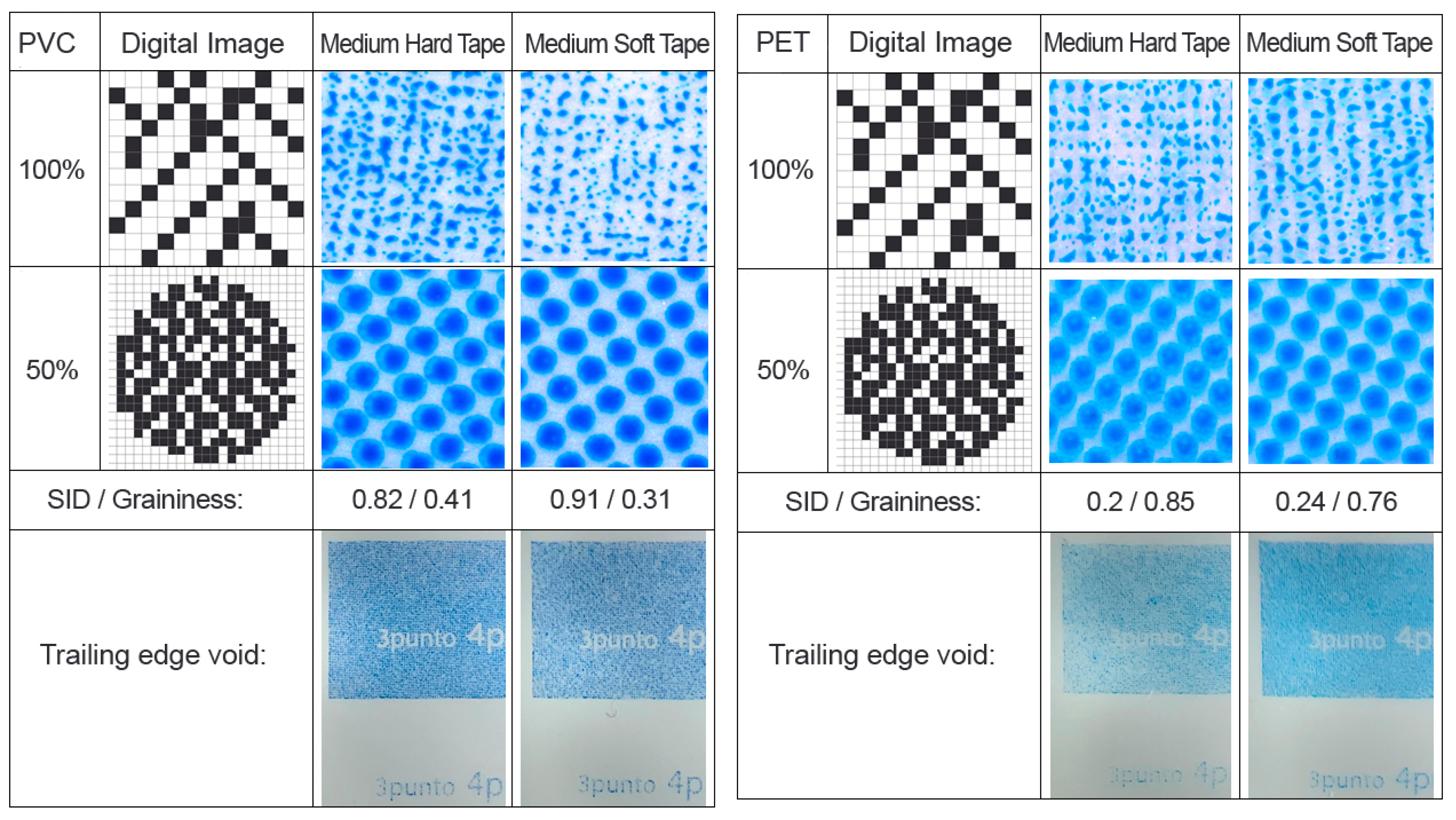
The printed areas magnified at 60× with a microscope in solis (100%) are shown in Figure 6, Figure 7, Figure 8, Figure 9, Figure 10, Figure 11, Figure 12, Figure 13 and Figure 14. When SID images without micro-pattern are examined, edge voids in the solid areas and rough appearance on the surface are observed. Graining is observed in the solid areas. In the PVC print substrate, shadowing occurred at points at 50% screen tone values. In PET printing material, rings are seen within the dots. These rings are caused by poor ink transfer to the solid areas.
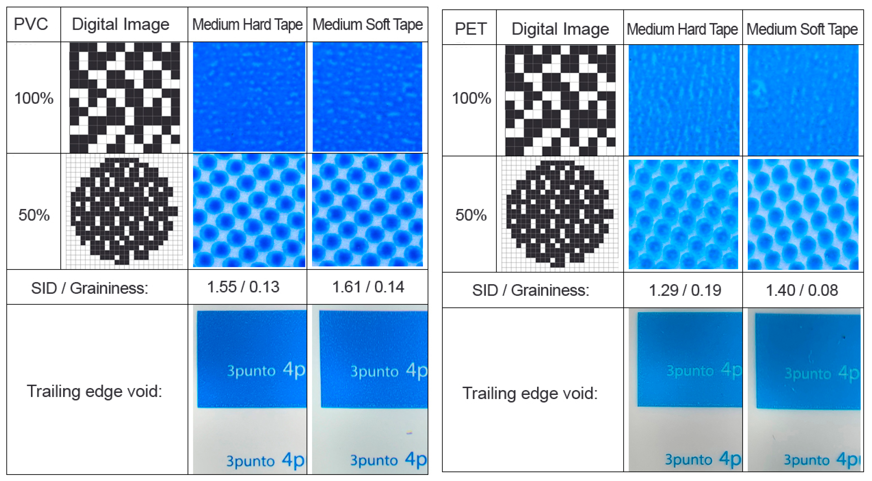
When the images in Figure 7 are examined, it is seen that although there is a slight increase in density in the solid areas of the micro-pattern 1 application compared to the non-pattern SIDs, there is no visual difference. It does not create a visible difference in dot areas, as it is on the solid areas.
When the images in Figure 8 are examined, it is seen that there is no significant difference in the density and ink laydown of the micro-pattern 2 application on the solid areas compared to the non-pattern SID and micro-pattern 1. It has been observed that the shadowing at the dots has decreased in the screening areas.
When the images in Figure 9 are examined, improvements were observed at the solid area density and ink laydown of the micro-pattern 3 application, which created on the solid areas compared to the non-pattern SID and micro-patterns 1 and 2 application. Especially in the prints made using PVC-printed Tesa 72,022 plate mounting tape, very clear results were obtained in both solid areas and screened areas.
When the images are examined according to Figure 10, it has been determined that the micro-pattern 4 application created is extremely successful in ink transfer of prints, regardless of the substrate material, both on the solid areas and in the screened areas, compared to all other developed micro-patterns on the solid areas. It has been determined that the trail edge void problem that occurs in the edge area of the printed solid areas, which is commonly encountered in flexo printing, has been completely eliminated.
When the images are examined according to Figure 11, Figure 12, Figure 13 and Figure 14, it is determined that the solid ink densities and screened dot areas of the micro-patterns created are gradually deteriorating and the ink transfer is extremely poor.
Newly developed micropatterns have made progress in SID compared to non-pattern systems. These SID and graininess improvements can be seen in Figure 9 and Figure 10.
As seen in Figure 15, the most successful results with the developed micro-patterns can be achieved with an average SID of 1.65 with Pattern 4 (1000 Lpi at 50%), while the average SID without micro-patterns is 1.45.
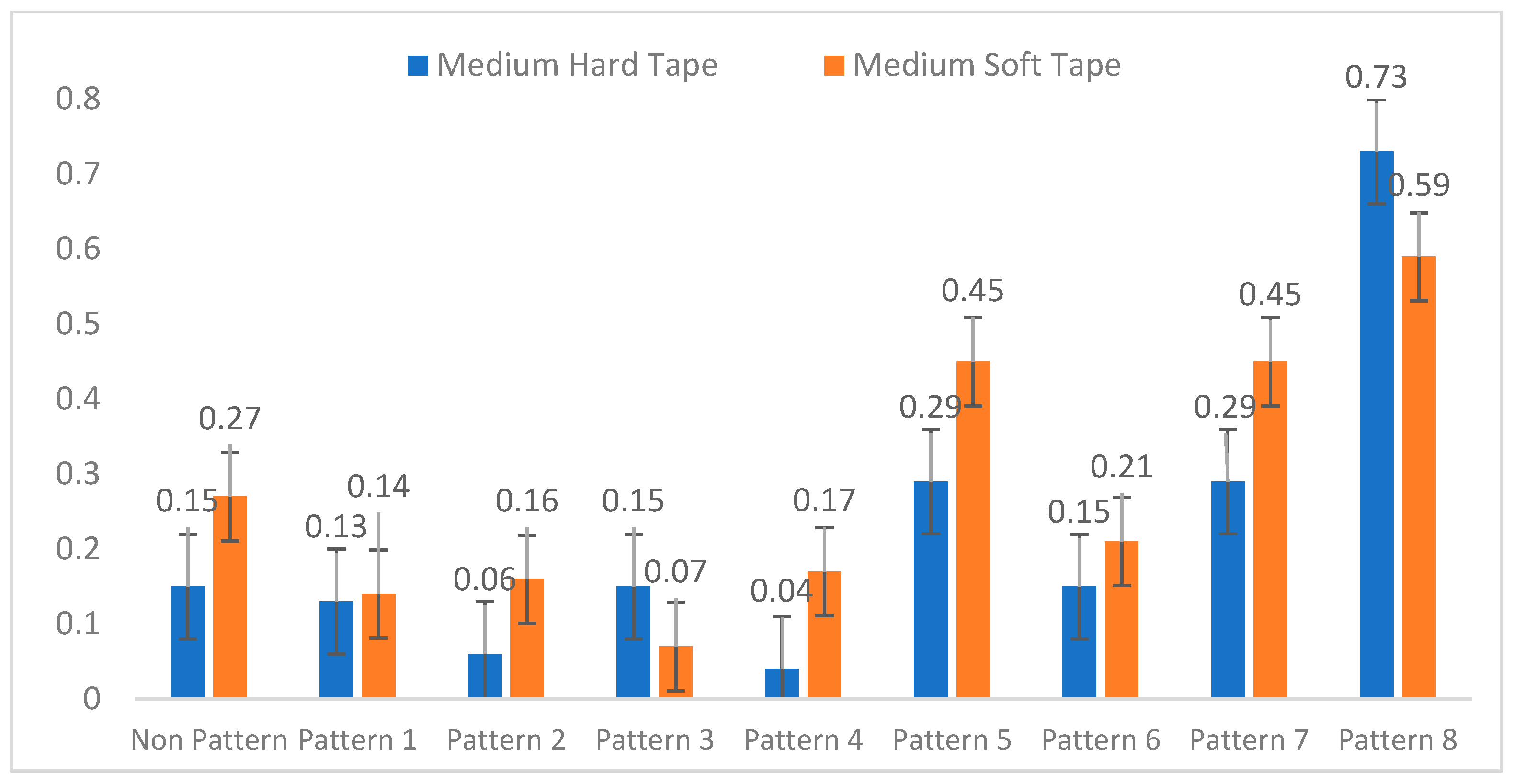
When Figure 16 is examined, the most successful of the developed micro-patterns is Pattern 4 (1000 Lpi at 50%), and the graininess average is 0.06, while this value is 0.21 without the micro-pattern.
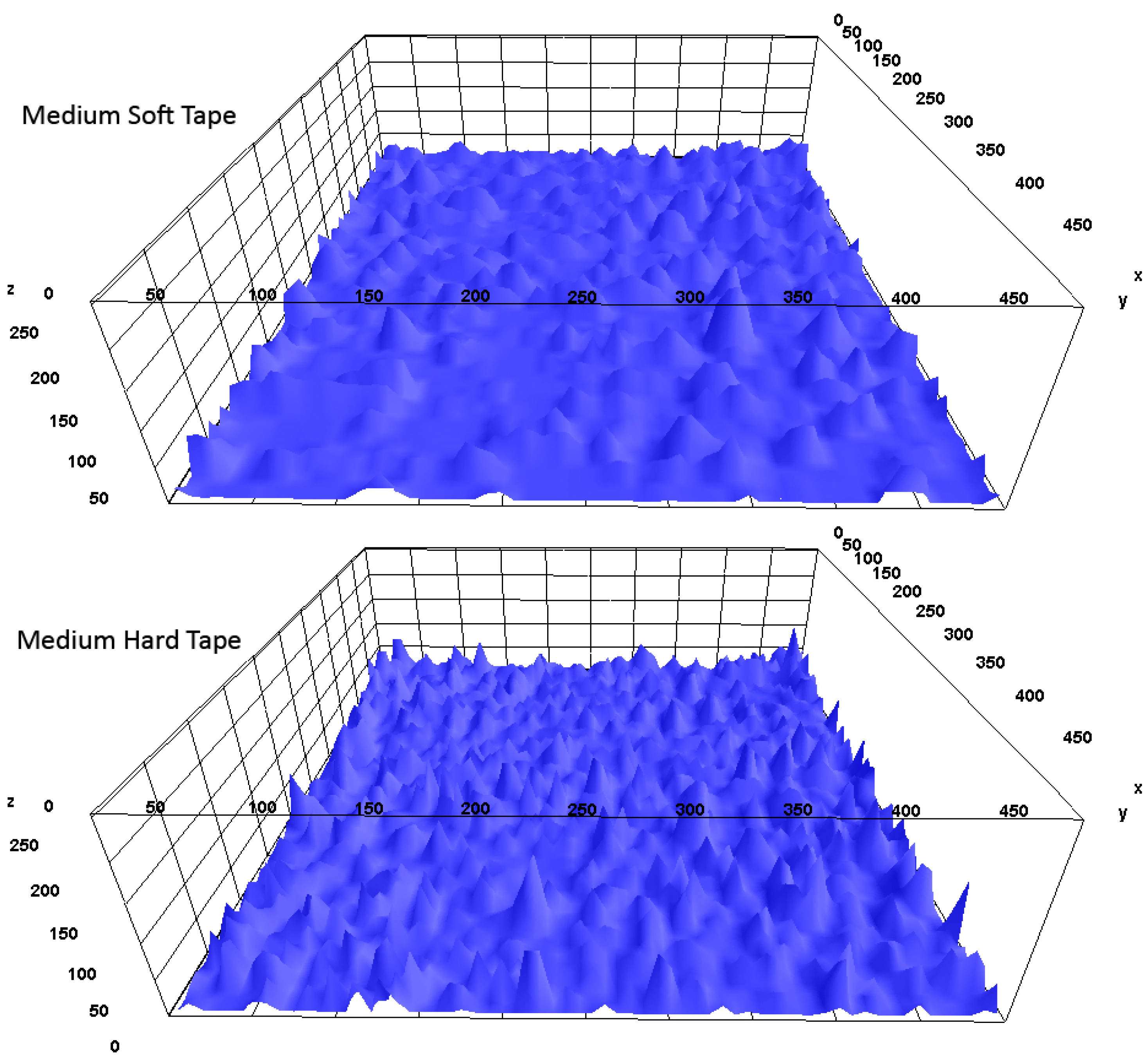
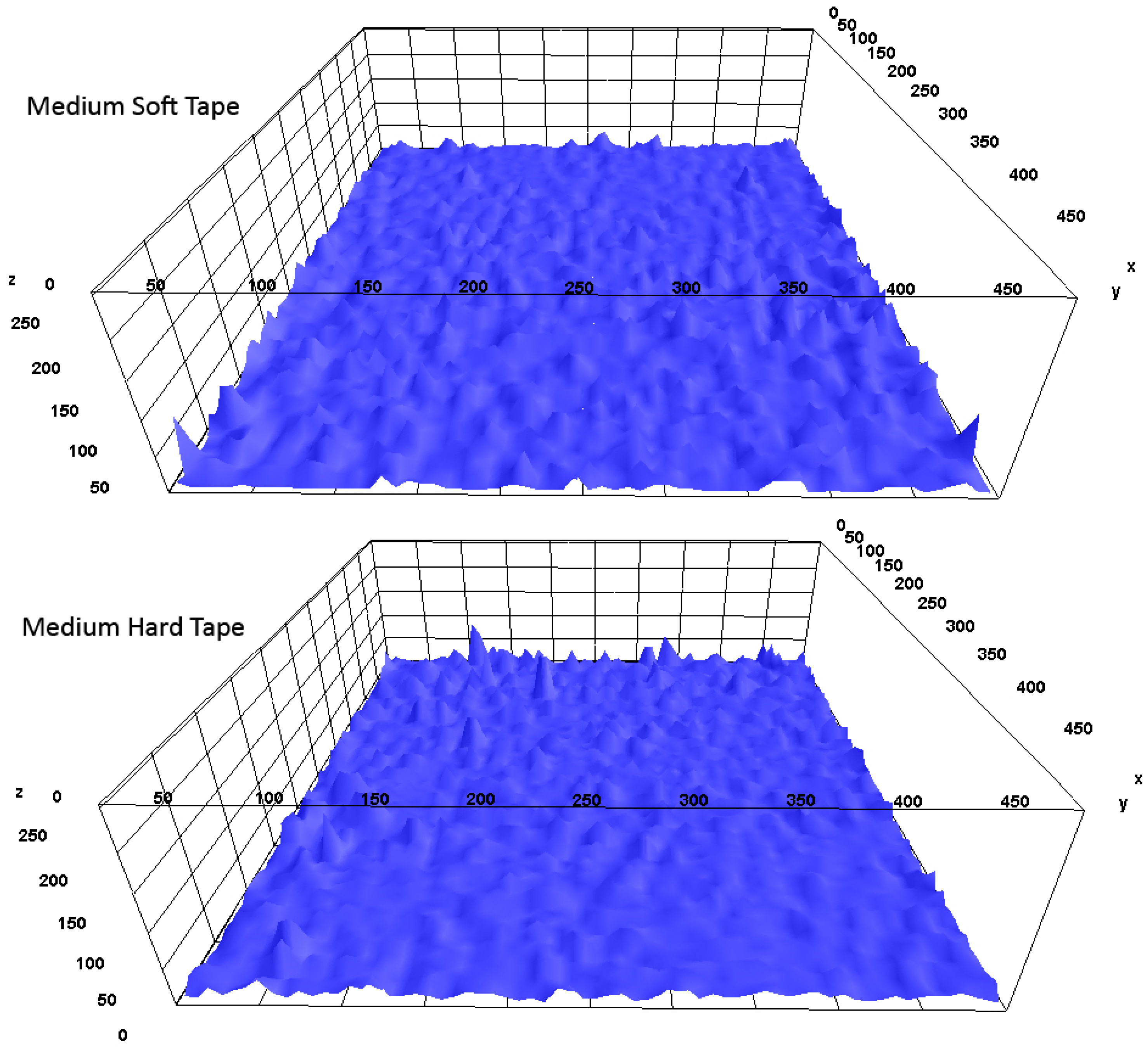
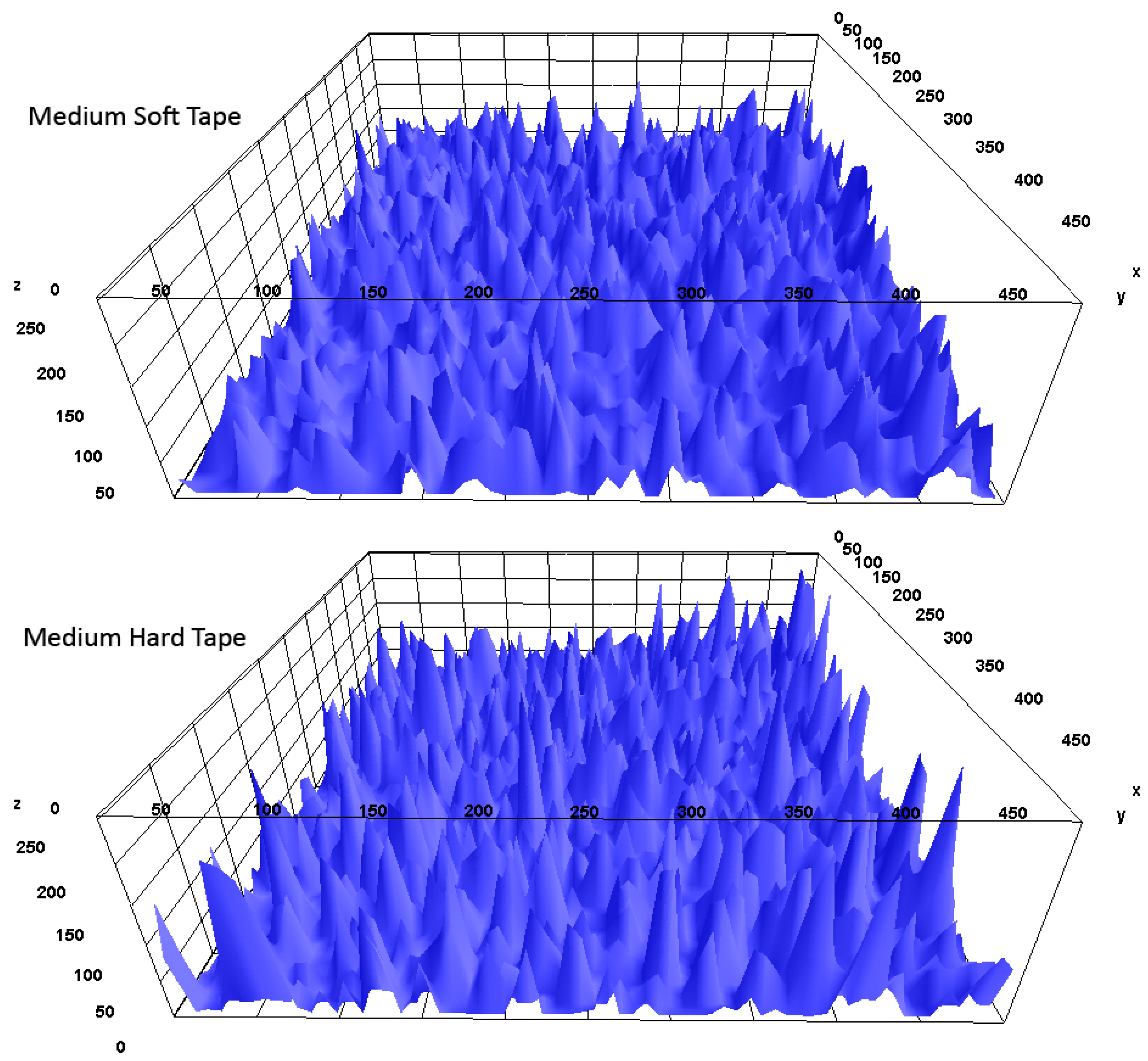
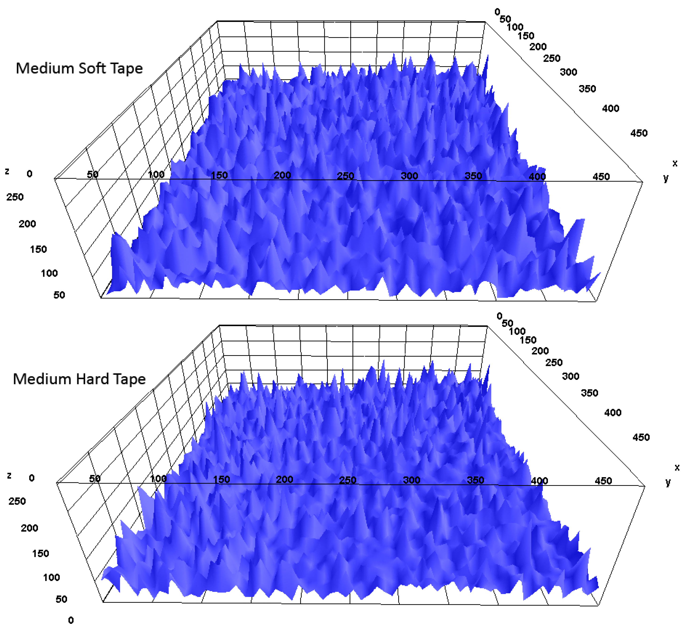
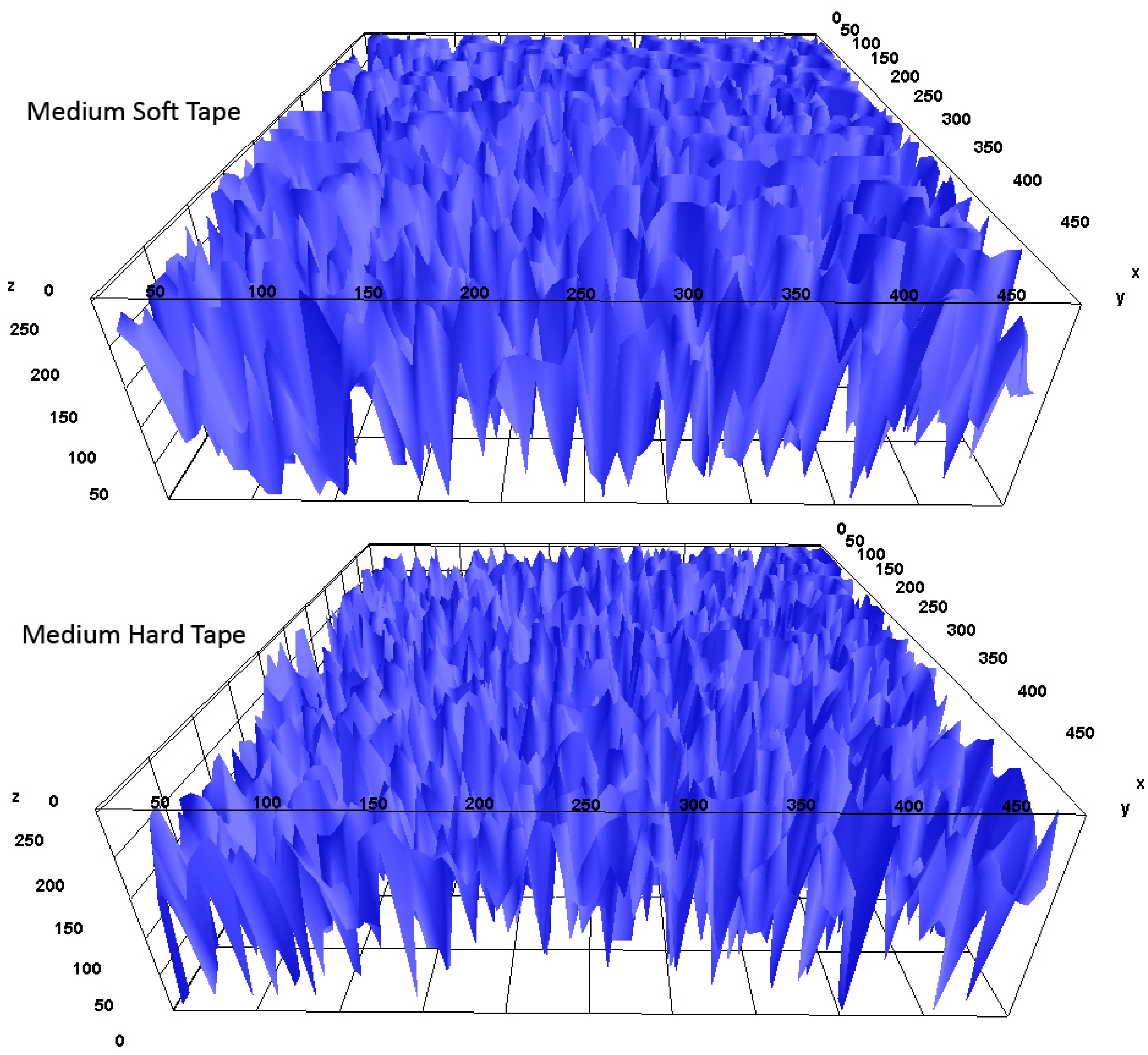
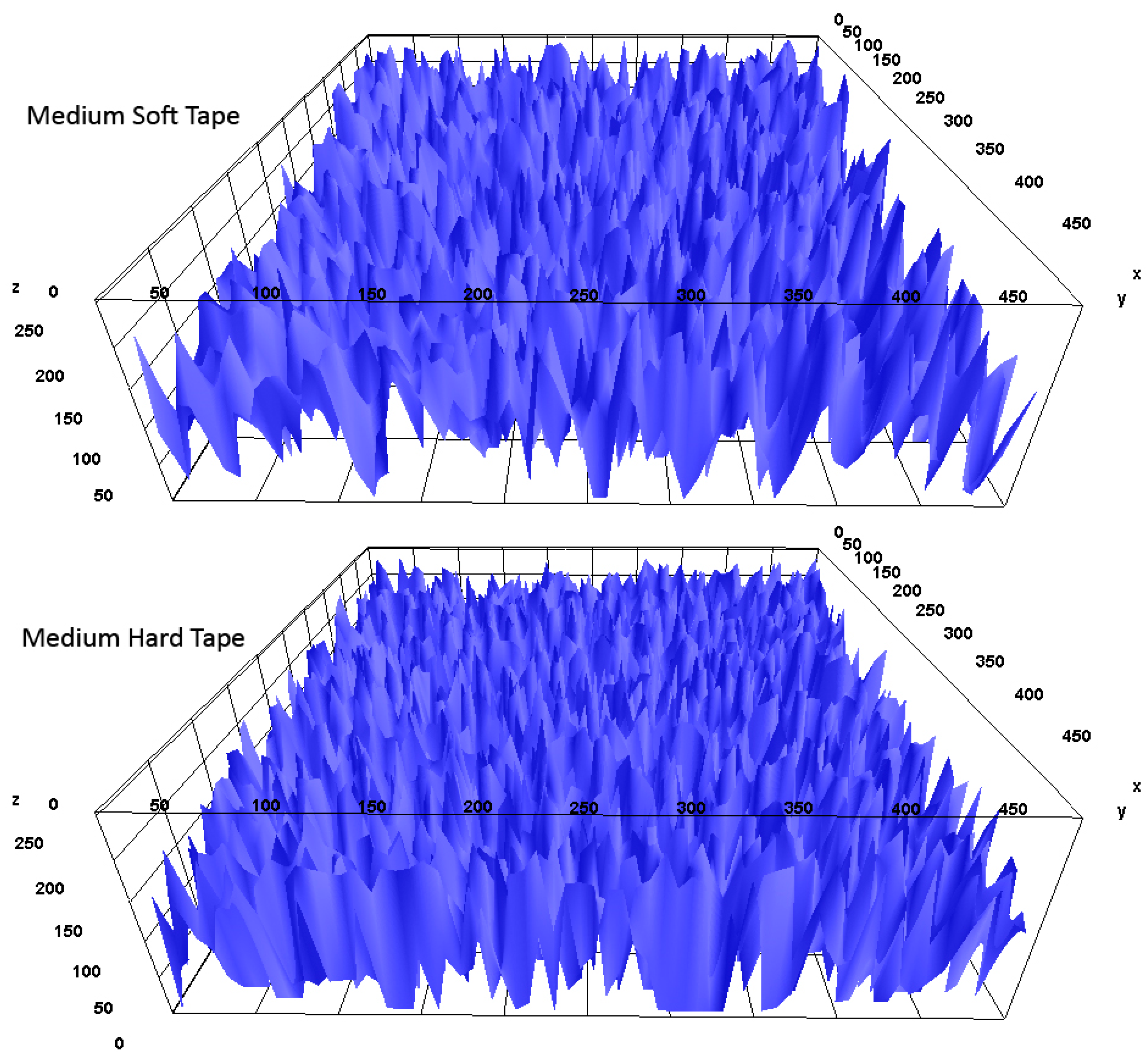
As seen in Figure 17 and Figure 18, all patterns’ surface graininess values were analyzed with the plot profile function. These figures show each micro-pattern graininess intensity with x-axis and y-axis; gray value 0 shows the darkest area and higher values show the lightest areas. All printed pattern results graininess is analyzed as topographic views with the 3D surface plot method. This also shows graininess intensity; the best results are shown as closer flatwise (Figure 19, Figure 20, Figure 21, Figure 22, Figure 23, Figure 24, Figure 25, Figure 26 and Figure 27).
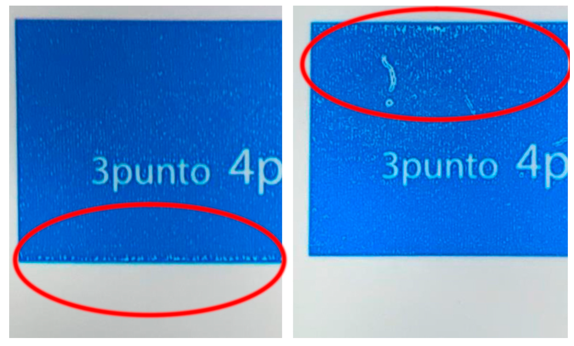
On the other hand, the visual results of the print results provide insight. Here, solid smoothness cannot be achieved on the surface on which no micro-pattern is applied, and also trail edge voids are observed (Figure 28).
The most successful solid edge from the eight different patterns prepared is Pattern 4. SID is the highest, and graininess is the lowest. In addition, there are no gaps on the solid edges (Figure 29).

4. Conclusions

As a result of all the examinations, significant differences were detected when the prints made without micro-pattern and with micro-patterns were examined. It has been observed that the ink cannot be transferred completely in areas without micro-patterns, while in areas with micro-patterns, the pattern ratio per unit area seriously affects the ink transfer.
In areas without micro-patterns, ink laydown is not fully successful because the ink accumulates on the plate but is not transferred well to the substrate. With the developed micro-patterns, trail edge voids in the solid areas and the ink accumulation edge of the screen dots are eliminated. Ink is distributed more homogeneously without graininess. It has been determined that this results in a more stable measurement of SID and eliminates the measurement of grainy solids and low SID.
In these micro-pattern studies, the best results in homogeneous laydown of ink transfer on the substrate were obtained with a micro-pattern that is filled with at least 50% of the unit area. If the micro-pattern ratio per unit area increases, it resembles a non-pattern structure. When the micropattern per unit area is applied at less than 50%, ink transfer decreases, SID drops, and ink laydown worsens.
This study has shown that reducing the cell volume of the anilox roller allows us to obtain a more uniform ink laydown with less ink on the corresponding micro-pattern.
According to Deganello, thinner lines offer the best height/width ratio, producing networks with better conductivity, clearly demonstrating the feasibility and value of flexographic processing using micropatterning of conductive structures [25].
This study was tested in the narrow web flexo. It is especially used in small-size packaging and label printing. This research is going to provide a solution for better ink transfer with plastic substrates for narrow web applications.

Author Contributions

Conceptualization, N.K.; Formal analysis, T.S.; Investigation, N.K.; Writing—original draft, N.K.; Writing—review & editing, T.S.; Funding acquisition, N.K. All authors have read and agreed to the published version of the manuscript.

Funding

This research received no external funding.

Institutional Review Board Statement

Not applicable.

Informed Consent Statement

Not applicable.

Data Availability Statement

The original contributions presented in the study are included in the article, further inquiries can be directed to the corresponding author.

Conflicts of Interest

The authors declare no conflicts of interest.

References

  1. Liu, X.; Guthrie, J.T. A review of flexographic printing plate development. Surf. Coat. Int. Part B Coat. Trans. 2003, 86, 91–99. [Google Scholar] [CrossRef]
  2. Keşan, N. Analysis of Parameters of Preproduction and Platemaking in Flexo Printing. Master′s Thesis, Marmara University, Istanbul, Turkey, 2008. [Google Scholar]
  3. Lorenz, A.; Senne, A.; Rohde, J.; Kroh, S.; Wittenberg, M.; Krüger, K.; Biro, D. Evaluation of flexographic printing technology for multi-busbar solar cells. Energy Procedia 2015, 67, 126–137. [Google Scholar] [CrossRef]
  4. Morisse, P.; Wolfgang, S. Method for Smoother Tonal Response in Flexographic Printing. U.S. Patent No. 11,142,013, 8 October 2021. [Google Scholar]
  5. Bielak, R.R. Flexographic Surface Patterns. U.S. Patent No. 9,235,126, 8 October 2014. [Google Scholar]
  6. Zhong, Z.W.; Ee, J.H.; Chen, S.H.; Shan, X.C. Parametric investigation of flexographic printing processes for R2R printed electronics. Mater. Manuf. Process. 2020, 35, 564–571. [Google Scholar] [CrossRef]
  7. Havenko, S.; Ohirko, M.; Ryvak, P.; Kotmalova, O. Determining the Factors That Affect the Quality of Test Prints at Flexographic Printing. East. Eur. J. Enterp. Technol. 2020, 2, 53–63. [Google Scholar] [CrossRef]
  8. Joshi, A.V. Optimization of flexo process parameters to reduce the overall manufacturing cost. Int. J. Optim. Control Theor. Appl. (IJOCTA) 2022, 12, 66–78. [Google Scholar] [CrossRef]
  9. Johnson, J.; Andersson, C.; Lestelius, M.; Jarnstrom, L.; Ratto, P.; Blohm, E. Some properties of flexographic printing plates and aspects of print quality. Appita Technol. Innov. Manuf. Environ. 2009, 62, 371–378. [Google Scholar]
  10. Assaifan, A.K.; Ahmad, I.; Alshehri, N.A.; Alharbi, H.F. Scaling-up medical technologies using flexographic printing. Talanta 2020, 219, 121236. [Google Scholar] [CrossRef] [PubMed]
  11. Bates, I.; Zjakic, I.; Budimir, I. Assessment of the print quality parameters’ impact on the high-quality flexographic print visual experience. Imaging Sci. J. 2015, 63, 103–110. [Google Scholar] [CrossRef]
  12. Olsson, R.; Yang, L.; Stam, J.; Magnus, L. Effects on ink setting in flexographic printing: Coating polarity and dot gain. Nord. Pulp Pap. Res. J. 2006, 21, 569–574. [Google Scholar] [CrossRef]
  13. Fang, E.; Ge, J. Research on the Solid Screening with Microcell Technology in the Flexographic Printing. In Proceedings of the 9th China Academic Conference on Printing and Packaging and Conference of Scientific Research Innovation, Jinan, China, 16–19 November 2018; pp. 543–550. [Google Scholar] [CrossRef]
  14. Várza, F.; Preklet, E.; Horváth, C. Application Analysis of White Flexographic Printing Inks on Biodegradable Flexible Foils. In Proceedings of the 2nd International Conference on Circular Packaging (2nd CPC), Slovenj Gradec, Slovenia, 9 September 2021; pp. 311–320. [Google Scholar] [CrossRef]
  15. Brumm, P.; Sauer, H.M.; Dörsam, E. Scaling Behavior of Pattern Formation in the Flexographic Ink Splitting Process. Colloids Interfaces 2019, 3, 37. [Google Scholar] [CrossRef]
  16. Valdec, D.; Hajdek, K.; Majnarić, I.; Čerepinko, D. Influence of printing substrate on quality of line and text reproduction in flexography. Appl. Sci. 2021, 11, 7827. [Google Scholar] [CrossRef]
  17. TAPPI T402 SP-13; Standard Conditioning and Testing Atmospheres for Paper, Board, Pulp Handsheets, and Related Products. Technical Association of the Pulp and Paper Industry (TAPPI): Peachtree Corners, GA, USA, 2013.
  18. ISO 536; Paper and Board—Determination of Grammage. International Organization for Standardization (ISO): Geneva, Switzerland, 2019.
  19. ISO 534; Paper and Board—Determination of Thickness, Density and Specific Volume. International Organization for Standardization (ISO): Geneva, Switzerland, 2011.
  20. FlintGroup Flexocure Force Process Cyan UFO5-0082-408N Specifications. Available online: https://www.cmyklinik.com/4531544 (accessed on 29 July 2024).
  21. ISO 5-4:2009; Photography and Graphic Technology—Density Measurements. International Organization for Standardization (ISO): Geneva, Switzerland, 2009.
  22. ISO 13655-2009; Graphic Technology—Spectral Measurement and Colorimetric Computation for Graphic Arts Images. International Organization for Standardization (ISO): Geneva, Switzerland, 2009.
  23. Şahinbaşkan, T.; Gençoğlu, E. Color and Color Management in Printing Industry; Odak Kimya Endüstri San.Tic.Ltd Şti: Istanbul, Türkiye, 2010; ISBN 978-605-88733-0-8. [Google Scholar]
  24. Kurt, M.B.; Mumcu, Y.K.; Özdemir, L. Estimation of screen density according to different screening methods with artificial neural network method in flexo printing. J. Polytech. 2018, 21, 575–580. [Google Scholar]
  25. Deganello, D.; Cherry, J.A.; Gethin, D.T.; Claypole, T.C. Patterning of micro-scale conductive networks using reel-to-reel flexographic printing. Thin Solid Film. 2010, 518, 6113–6116. [Google Scholar] [CrossRef]
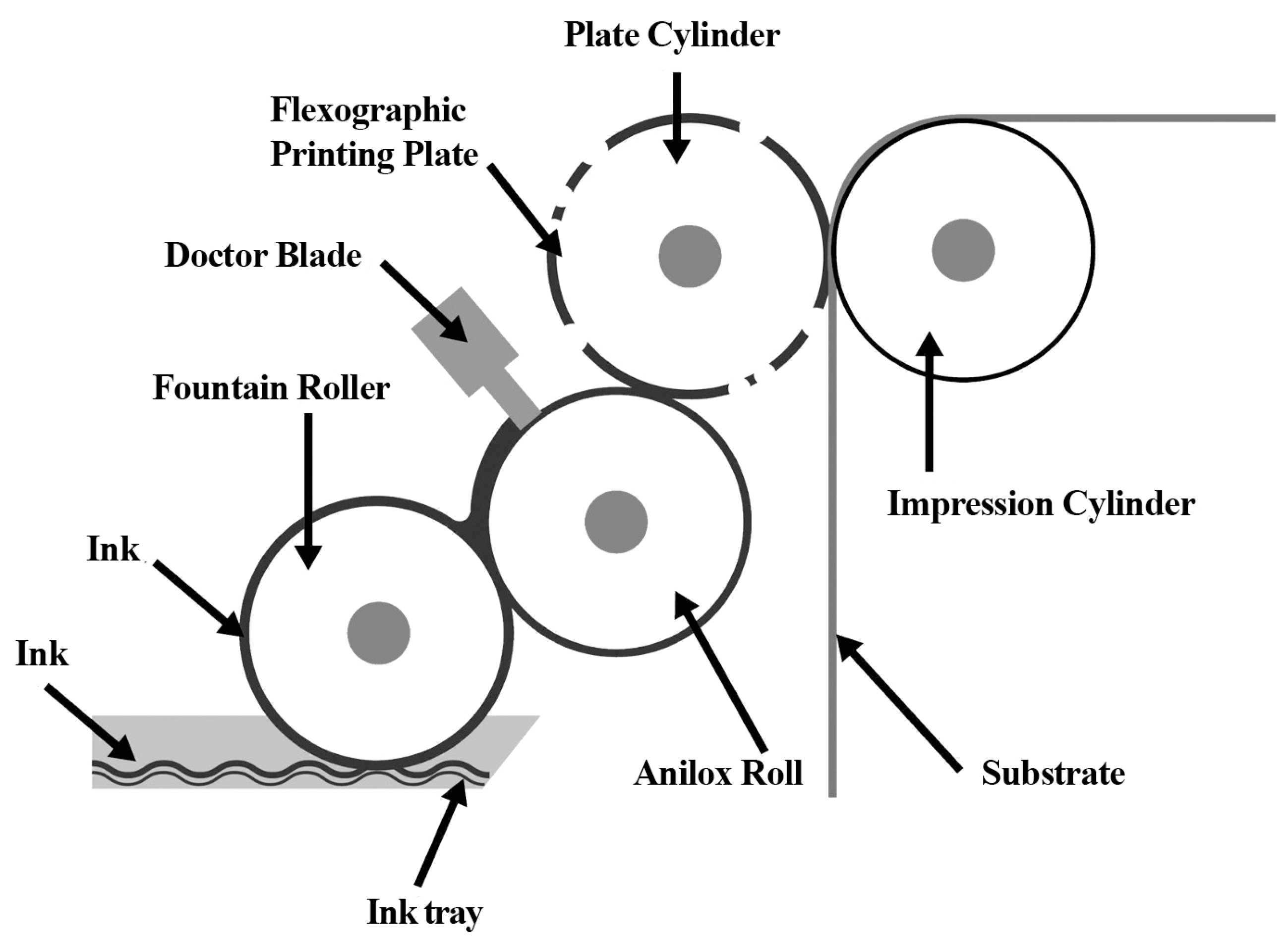
Figure 1. Flexo printing system.
Applsci 14 08130 g001
Figure 2. Fotopolymer flexo printing plate.
Applsci 14 08130 g002
Figure 3. Printed test page.
Applsci 14 08130 g003
Figure 4. Designed micro-pattern types.
Applsci 14 08130 g004
Figure 5. SID formulation [23].
Applsci 14 08130 g005
Figure 6. Non-pattern print results.
Applsci 14 08130 g006
Figure 7. Pattern 1 print results.
Applsci 14 08130 g007
Figure 8. Pattern 2 print results.
Applsci 14 08130 g008
Figure 9. Pattern 3 print results.
Applsci 14 08130 g009
Figure 10. Pattern 4 print results.
Applsci 14 08130 g010
Figure 11. Pattern 5 print results.
Applsci 14 08130 g011
Figure 12. Pattern 6 print results.
Applsci 14 08130 g012
Figure 13. Pattern 7 print results.
Applsci 14 08130 g013
Figure 14. Pattern 8 print results.
Applsci 14 08130 g014
Figure 15. Printed solid ink density values.
Applsci 14 08130 g015
Figure 16. Graininess values.
Applsci 14 08130 g016
Figure 17. Graininess intensity for each pattern (medium-soft tape).
Applsci 14 08130 g017
Figure 18. Graininess intensity for each pattern (medium-hard tape).
Applsci 14 08130 g018
Figure 19. Non-pattern graininess analysis.
Applsci 14 08130 g019
Figure 20. Pattern 1 graininess analysis.
Applsci 14 08130 g020
Figure 21. Pattern 2 graininess analysis.
Applsci 14 08130 g021
Figure 22. Pattern 3 graininess analysis.
Applsci 14 08130 g022
Figure 23. Pattern 4 graininess analysis.
Applsci 14 08130 g023
Figure 24. Pattern 5 graininess analysis.
Applsci 14 08130 g024
Figure 25. Pattern 6 graininess analysis.
Applsci 14 08130 g025
Figure 26. Pattern 7 graininess analysis.
Applsci 14 08130 g026
Figure 27. Pattern 8 graininess analysis.
Applsci 14 08130 g027
Figure 28. Trail edge voids—no pattern applied. The mounting tape used was medium-hard on the left and medium-soft on the right.
Applsci 14 08130 g028
Figure 29. No trail edge voids are observed. The mounting tape used is medium hard on the left and medium soft on the right.
Applsci 14 08130 g029
Table 1. Micro-pattern specifications.
Pattern NumberPattern Resolutions
11500 lpi tonal value 60%
21000 lpi tonal value 60%
31500 lpi tonal value 50%
41000 lpi tonal value 50%
51500 lpi tonal value 40%
61000 lpi tonal value 40%
71500 lpi tonal value 30%
81000 lpi tonal value 30%
Table 2. Micro-pattern bitmap matrix forms.
Pattern 1
111101111010
011001001100
110110111011
100110011001
111001111110
011011100100
100110011011
110110111001
011001001100
111011101100
100110011011
111110111011
Pattern 3
111011001101
001100110011
001100110101
110011001100
110101100111
001100110011
001001011101
110011001100
101010110011
001100110111
111001010101
110011001100
Pattern 5
110011001000
000100100110
001100110100
010010001001
110111000111
001000110010
100001011101
110011001000
001100110001
001000100010
100011001101
010010001000
Pattern 7
000101000100
100010011001
010101010100
001001100010
010001010001
010010001000
000100010100
001000100010
010001000101
100010010100
000100010100
001000100010
Pattern 2
110011110011
110001100001
111010110011
011100011100
011110011100
110111110110
100011100011
110011110011
111110111110
011100011100
011110011100
110011110011
Pattern 4
001100000110
001011011010
110000110001
110001110001
011011001011
001110000110
001110001110
011001011011
110001110001
110001110001
001011001010
000110001110
Pattern 6
101101001000
110000111001
111001111000
000011110111
000110000110
000110000110
101000101001
110000110000
110000111001
000111000101
000110000110
000101000110
Pattern 8
110000110000
110000000000
000110000000
000110000000
000001000010
110000110000
110000110000
001000001000
000111000110
000110000110
000001000001
110000110000
Table 3. Micro-pattern print SID and graininess results.
SubstratePVCPET
TapeMedium-Hard Tape Medium-Soft Tape Medium-Hard Tape Medium-Soft Tape
SIDGraininessSIDGraininessSIDGraininessSID Graininess
Non-Pattern1.520.151.410.271.210.211.260.12
Pattern 1 1.550.131.610.141.290.191.40.08
Pattern 2 1.640.061.550.161.310.191.40.07
Pattern 3 1.510.151.620.071.370.081.340.11
Pattern 4 1.660.041.510.171.430.031.40.04
Pattern 5 1.320.291.250.451.20.271.140.35
Pattern 6 1.440.151.380.210.860.481.130.37
Pattern 7 0.820.410.910.310.20.850.240.76
Pattern 8 0.660.730.650.590.520.630.550.55
Disclaimer/Publisher’s Note: The statements, opinions and data contained in all publications are solely those of the individual author(s) and contributor(s) and not of MDPI and/or the editor(s). MDPI and/or the editor(s) disclaim responsibility for any injury to people or property resulting from any ideas, methods, instructions or products referred to in the content.