Abstract
The risk posed by expansive soils can be lessened by placing foundations at a more deep level below the surface. Structures are able to withstand uplift forces because overburden pressure partially suppresses swelling pressure. In order to transfer the forces to a sufficiently deep depth, this study suggests introducing shafts of a low-expansion overburden material. Soil improved with cement is chosen for this purpose. This study suggests using sand with added excavated natural clay and cement. The expansive clay is added to sand in ratios of 10, 20, 30, 40 and 60%. The clay–sand mixture is then enhanced by cement of 1, 2, 4 and 8% by the weight of the mixture under four curing periods of 1, 7, 28, and 90 days. This material is recommended for use under lean concrete to transfer the loads to lower levels below the foundation depth. The thickness of this material depends on the stresses exerted, the type and the properties of the subsurface soils. The cement-enhanced clay–sand shaft’s properties are examined in this work with regard to the swelling potential, compressibility, and the unconfined compressive strength for different clay contents and curing conditions. Stiff shafts were formed and found to support stresses from 600 to 3500 kPa at cement additions in the range of 1% to 8%. Clay content above 30% is found to be not suitable for Al-Qatif clay due to the compressibility and low strength of the mixture. When two percent or more of cement is added, the swelling potential is significantly reduced. This is reliant on the pozzolanic interactions of soils and cement as well as the clay mineralogy. Determining how cement affects clay–sand combinations in regions with expansive soils would facilitate the introduction of a novel, inexpensive technology to support loads applied by the superstructure.
Keywords:
cement; expansive clay; sand; mixtures; foundations; sand columns; compressibility; compression strength; swelling; stabilization 1. Introduction
The stabilization of expansive soil using cement and lime is a known procedure to halt the expansion mechanism that occurs on wetting. Soils classified as expansive undergo notable alterations in volume that are linked to variations in water content. The soil may swell or contract as a result of these volume changes [1]. An important part of expansive soils is made up of expanding clay minerals, which contract and expand in response to moisture and drying.
Cement-stabilized soils’ laboratory engineering characteristics have been the subject of many studies on the effects of some key variables, such as the water content, cement content, curing time, and compaction state [2,3,4,5]. These were conducted addressing clay in general but were not tailored to suit expansive clay soils. Very few studies were focused on highly plastic and expansive clay. Khemissa and Mahamedi [6] investigated the cement and lime mixture stabilization of an expansive overconsolidated clay from Algiers. In addition, Goodarzi et al. [7] addressed the stabilization of highly expansive clays by mixing cement and silica fume.
Significant parts of Saudi Arabia are covered with soils rich in expansive minerals. The areas of Al-Ghatt, Tabuk, Tayma, Al-Jawf, Sharoura, Al-Medina, Al-Qatif, and Al-Hafuf reported the presence of the expansive soil formations. In the distribution of expansive soil in the Kingdom of Saudi Arabia, Al-Qatif clay is the most expansive clay in the country and was selected for use in this study.
When encountering expansive soil, the excavated material can be mixed with sand for reuse as a backfill material. This mix can be further enhanced with cement to exclude the adverse effect of clay within the mix and reduce the costs that include waste disposal. It is customary to combine clay material with coarse-grained or medium-grained sand. The prevailing belief is that the mixture’s coarser fraction results in a comparatively strong shear strength and high compacted density, whereas the proportion and index characteristics of the finer fraction determine the soil’s hydraulic conductivity [8]. A sand-sized fine aggregate mixed with clay improved the mechanical characteristics and compaction, according to Mitchell and Soga [9]. The effectiveness of sand–natural clay combinations employing locally accessible clay resources has been the subject of a small number of recent studies [10,11,12,13,14].
The idea of applying cement-stabilized columns for expansive soils is derived from the studies by Chen et al. [15] in which ground improvement is obtained using soil–cement column-reinforced foundations. Figure 1 below is showing the method of stabilization. In order to widen this approach to cover footings supporting a light structure resting on expansive soil, columns can be enlarged to cover the entire area below the footings. In this study, the focus is not directed towards the geometry but towards the stabilized material and the depth needed to add a sufficient surcharge load.
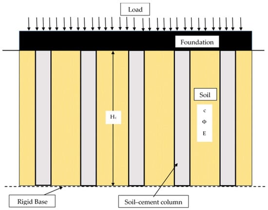
Figure 1.
Soil–cement column arrangements suggested to support structures.
The use of cement-stabilized columns is a technique that can be used in real-world applications for geographical areas and zones of expansive soils where damage to structures and pavements were reported. The approach provides an improvement to the subgrade soil and can increase the bearing strength, stabilize the subsurface soils and reduce the risk of expansion [16,17].
There are many factors influencing cement stabilization. These include the mineralogy, clay content, water content, curing time, mixing, the compaction method and others. Al-Qatif clay is a highly plastic material and was found to be rich in montmorillonite and palygorsite, which are typical swelling minerals. The percentages of montmorillonite and palygorsite in this clay are between 3% and 23% and 5% to 33%, respectively [18]. The water content is kept constant for every cement content amount as all materials are compacted to the optimum moisture content. The compressibility, the swelling potential and the unconfined compressive strength are investigated at variable curing times ranging from 1 day to 90 days.
This work presents the geotechnical and engineering properties of a cement-stabilized clay–sand mixture column, block or a number of columns suggested to be used under footings in expansive clay areas. The properties addressed here include the swelling potential, the compressibility and the unconfined compressive strength at different curing times. The clay content is also viewed as a factor in determining the column strength.
2. Materials
2.1. Sand
This study considered a sand material, which has been used in construction and research in numerous studies of sand–clay composites. This sand has been quality-controlled and is often utilized in the concrete and building construction industry. The sand material is appropriate for use in this study because it is devoid of any biological components or other impurities. The specific gravity and particle size distribution were two aspects of the geotechnical characterization of the sand material. Table 1 provides an overview of the geotechnical characterization data. The Unified Soil Classification System (USCS) designated the sand as poorly graded sand.
2.2. Expansive Clay
The natural clay from Al-Qatif, a town in the eastern province of Saudi Arabia, was utilized for this study. Al-Qatif clay is an expansive soil that is found along the east coastal line of Saudi Arabia. In its unsaturated state, this kind of clay is highly fissured and changes its volume significantly when the water content is changed. Al-Qatif clay’s geotechnical properties were the subject of several earlier investigations, which found that the clay is highly plastic and expansive [19,20,21,22,23,24]. The clay minerals include illite, smectite, and attapulgite, which are found to be responsible for the volume change and the swelling potential [21]. Clay samples were extracted from a test pit in Al-Qatif and brought to the laboratory for in-depth geotechnical, chemical, and mineralogical analysis. Table 2 provides a summary of the physical parameters of Al-Qatif clay. Table 3 provides the chemical makeup of this particular clay type. The XRD technique was utilized to detect the main minerals contained in Al-Qatif expansive clay. The XRD spectra of expansive clay show multi-peaks with varied intensities at different 2θ values, showing that Al-Qatif expansive clay contains more than one mineral, as shown in Figure 2.
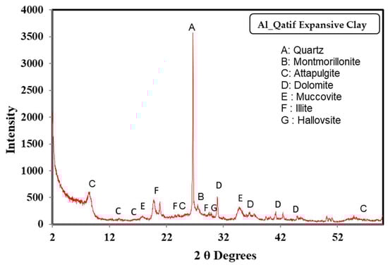
Figure 2.
The XRD profile for Al-Qatif expansive clay.
The SEM was employed to observe the microfabric features of Al-Qatif expansive clay.
2.3. Cement
In this investigation, the cement used was the ordinary Portland cement (OPC-Type I). The Yamama Saudi Cement Company, located in Riyadh, Saudi Arabia, produces the OPC. The results of characterization testing showed that the cement’s specific gravity is 3.12.

Table 1.
Properties of sand.
Table 1.
Properties of sand.
| Property | Value | Standard Used |
|---|---|---|
| Specific gravity | 2.66 | ASTM D854 [25] |
| Range of particle size (mm) | 0.1–0.6 | |
| Coefficient of uniformity | 1.737 | ASTM D2487 [26] |
| Coefficient of curvature | 1.078 | ASTM D2487 [26] |
| USCS classification | Poorly graded sand | ASTM D2487 [26] |
Table 2.
Physical properties of Al-Qatif clay.
Table 2.
Physical properties of Al-Qatif clay.
| Property | Value | Standard Used |
|---|---|---|
| Liquid limit (%) | 140–150 | ASTM D4318 [27] |
| Plastic limit (%) | 45–50 | ASTM D4318 [27] |
| Plasticity index (%) | 95–100 | ASTM D4318 [27] |
| Specific gravity | 2.76 | ASTM D854 [25] |
| USCS classification | CH | ASTM D2487 [26] |
| Swelling potential (%) | 20–25 | ASTM D4546 [28] |
| Swelling pressure (kN/m2) | 500–600 | ASTM D4546 [28] |
Table 3.
Chemical composition of Al-Qatif clay.
Table 3.
Chemical composition of Al-Qatif clay.
| Chemical Compound | Percentage (%) |
|---|---|
| Na2O | 0.50 |
| MgO | 4.92 |
| Al2O3 | 15.82 |
| SiO2 | 55.86 |
| K2O | 5.22 |
| CaO | 1.74 |
| FeO | 9.39 |
3. Experimental Program
3.1. Sample Preparation of Mixtures
In order to conduct this study, some of the parametric factors of soil, such as the initial water content and dry density, were kept constant and similar to enable comparison and help in examining the effect of cement. In this study, four different percentages of regular Portland cement content were used: 1, 2, 4 and 8% by the dry weight of sand. The cement content range was chosen based on the known trials in the literature; however, more than 8% cement was expected to form a rigid non-workable paste. Five distinct sand–expansive clay (Qatif) combinations containing 10, 20, 30, 40 and 60% expansive clay were prepared. There were four distinct curing times used for each mixture: 1, 7, 28 and 90 days. The expansive clay content range was selected to cover all practical ratios that are likely to be present in soils showing expansive behavior. The clay was air-dried, ground into a powder, and sieved through sieve No. 40. To create a uniform blend, the desired ratios of oven-dried sand, clay, and cement were manually combined in a dry environment. As advised by ASTM Standard D698 [29], the desired water content was then added as shown in Table 4, well mixed, and the plastic bags containing the mixtures were then stored in a humid environment for at least 16 h to give the soil particles time to hydrate under a controlled relative humidity greater than 95% and an ambient temperature of 23 °C ± 1 °C. In order to achieve the desired unit weights, samples were prepared by static compaction in a stainless-steel odometer ring of 63.5 mm in diameter and 20 mm in height. To lessen the side friction, silicon grease was put on the ring’s inner surface. The compacted sample was topped and bottomed with filter paper and a porous stone. The ultimate sample height of 16 mm was maintained, with a 4 mm gap to accommodate sample expansion.
Table 4.
Compaction data for all mixtures with different clay contents.
3.2. Curing of the Mixtures
The mixtures were allowed to cure for 1, 7, 28 and 90 days prior to testing in order to examine the effect of curing time on all tests for various cement additives. This was found to be sufficient to achieve most of the strength gained by hydrating the mixtures.
3.3. Oedometer Testing
In accordance with ASTM D4546 [28], a series of one-dimensional odometer tests were conducted to assess the compressibility and swelling behavior of the mixtures. Four basic steps were engaged in the process for all tests: dry loading, wet loading, unloading, and free swell (swelling under a seating load). For a brief period of time (15 min), dry loading was provided with a seating load of 7 kPa to ensure that the air was released and that the sample’s cover cap and rod made contact. In order to measure free swell, samples were submerged at the same 7 kPa seating load while vertical strain (heave) was continuously monitored. When there is no evidence of further significant deformation, equilibrium heave is assumed to be reached. The time it took to reach equilibrium heave was typically between 24 and 36 h, dependent on the amount of clay in the mixture. Samples were gradually loaded with a standard load increment ratio of 1 up to 400 kPa after reaching equilibrium. Until initial consolidation was finished, each stress was sustained (24 h). An LVDT was used to track the sample’s vertical deformation throughout the test. At the conclusion of every loading phase, the vertical strain was assessed using these vertical deformation data. The samples were unloaded (rebound) at a load increment ratio of 25% after reaching their maximum compression stress. At the end of the test, the water content of the sample was determined. The entire test takes eight to ten days to complete. The consolidation and unloading curves were plotted to illustrate the relationship between the applied stress (on a logarithmic scale) and the void ratio. A schematic representation of these curves is displayed in Figure 3, which includes the steps of the test and definitions for the key parameters: the compression index (Cc), the rebound index (Cr), and the swelling value (SP).
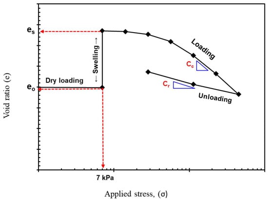
Figure 3.
A typical consolidation curve illustrating the key parameters (Cc and Cr) and basic steps of the test.
3.4. Unconfined Compression Test
The unconfined compressive strength (UCS) for clay–sand mixtures with cement additives was evaluated following a test procedure in accordance with ASTM D5102 [30]. The main purpose of this test is to determine the change in the compressive strength and behavior of sand-expansive clays at variable curing periods (i.e., 1, 7, 28 and 90 days) and with different cement contents (1, 2, 4, and 8%).
The sand was screened through a 0.85 mm (No. # 20) sieve to eliminate impurities. The optimum water content and maximum dry unit weight of the mixtures were obtained using a standard proctor compaction test according to ASTM D698 [29], as mentioned in Table 4.
A group of five samples was prepared for each mixture. The test was applied to the first sample group after 24 h. After wrapping with thin tensile cellophane, in order to not lose water content, the other four sample groups were kept in a desiccator. After curing, the specimens were loaded to failure at a constant strain rate of 1% per minute in a compression machine. The mold sizes for unconfined compression strength tests were 50 × 100 mm as per ASTM D5102 [30] and ASTM D2166 [31].
4. Results and Discussion
4.1. Applications of the Cement-Enhanced Clay–Sand Columns
The targeted application of this cement treatment method is to improve the soil immediately below a foundation to an extended deep level. This is expected to transfer the superstructure loads down to a deep strata where the overburden pressure is high. The stabilized clay–sand column can transfer the contact pressure to a deep level soil within the natural expansive clay formation. The strength of the clay–sand column is lower than that of the lean concrete used to transfer the stresses to the ground. The cement-rich mix makes the soil stiffer and can safely transfer the stresses. The laboratory tests conducted in this research were aimed at investigating the effect of the cement dose, curing time and clay content on the compressibility, swelling potential and the compressive strength. The swelling pressure of the ground needs to be counterbalanced by vertical loads from the super structure and the overburden soil pressure. The study presented here is limited to the assessment of the material suggested to act as a shaft, transferring loads to the ground. Other studies on deep mixing using cement or other stabilizers for expansive soils tend to improve the nature of the supporting ground but lack efficient quality control methods and are faced with practicality issues [32,33,34]. Mixing procedures can be manual or mechanical at variable speeds and forces to attain a homogeneous mix. The deep mixing method proved to be successful in enhancing soft soils and increasing the bearing pressure. Al-Qaisi and Al-Waily [35] showed that deep mixing significantly reduced settlement by average percentages ranging from 33% to 89%, and increased the bearing capacity by up to 2.43 times for soft clay soils treated with cement or lime. Also, Puppala and Pedarla [36] presented deep mixing as an innovation technique to improve the performance of structures placed on expansive soils. They observed that the soil sections treated with lime and cement did not undergo any movement compared to the untreated sections. The process in this proposal is different in that all soils under the foundation need to be excavated and replaced by a controlled mixture of sand, clay and cement at specified ratios and moisture contents, then placed and compacted in layers using tampers and left to cure for at least seven days before the superstructure foundations should be placed. The selection of the stabilized shaft or column below the foundation needs to be based on successful laboratory tests to confirm an adequate strength and compressibility with a low or non-significant swelling potential. Tapering the shaft to increase the contact pressure is an option in the case where the swelling pressure of the soil is high.
Other applications of the cement-enhanced clay–sand columns include pavements, boundary walls and slab-on-grade systems. The columns can be extended to a depth at which the swelling pressure will not be a risk to the superstructure.
In Figure 4 and Figure 5, it was assumed that the friction between the clay–sand column and the clay is low and that no uplift can take place. This can be avoided by placing the columns in loose contact with the original soil using a flexible material or forms. Tapering is enhanced by forms which can be designed as needed.
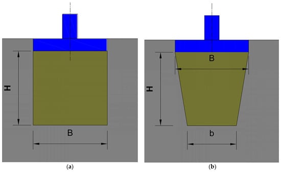
Figure 4.
Cement-treated shaft under foundation: (a) Regular, (b) Tapered.
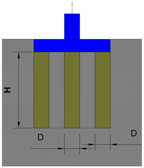
Figure 5.
Rigid column support.
4.2. The Soil Overburden Pressure
It was found that the soil overburden pressure exerts stresses on the ground and reduces the uplift forces arising from expansive soils. When the swelling pressure is established as 80 kPa, foundations placed at a 4 m depth will exert almost 80 kPa of pressure for soil with a bulk density of 20 kN/m3. The depth of the foundation can always help in reducing uplift forces. Bringing down all foundations to a required depth might be costly and may require a comprehensive redesign exercise. The idea of utilizing a cement-enhanced material under the footings can be a good solution to avoid unwanted upheaval movement.
4.3. The Compressibility Characteristics
The compressibility characteristics for clay–sand mixtures enhanced with cement is studied for cement additives of 1%, 2%, 4% and 8%.
Figure 6a,b indicate the variations of compression index (Cc) (Figure 6a1–a4) and rebound index (Cr) (Figure 6b1–b4) under curing times for variable cement additives.
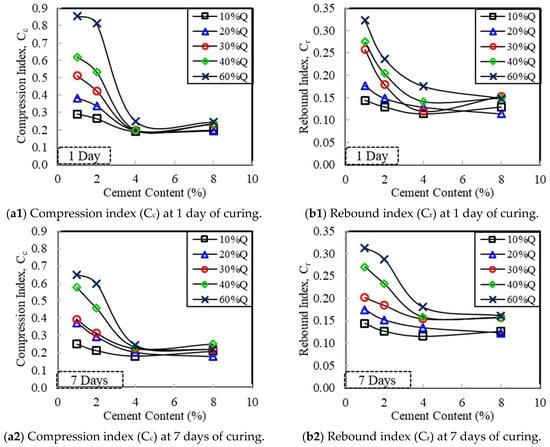
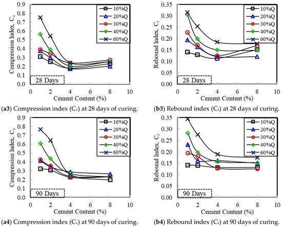
Figure 6.
Compression and rebound indexes of mixtures vs. cement contents at all curing days: (a1–a4) compression index (Cc), (b1–b4) rebound index (Cr).
It is clear that, as the cement content increased, the compression index (Cc) declined noticeably. Samples that had been cured for 28 days had Cc decreases by 29% to 64%. As the cement concentration increased, the rebound index (Cr) dropped. Samples cured for 28 days indicated a reduction in Cr by 19% to 51%.
The potential for settling can be estimated using the compressibility factors when evaluating a shaft for superstructure load transformation. It is important to remember that this compressibility is predicated based on inflexible lateral confinement, which is not an accurate representation of the actual field conditions. Avoid using cement-enhanced columns and make sure they do not buckle when used as self-supporting structures.
Comparing specimens with 30% and 40% clay contents to those with 10% and 20% clay contents, there was a greater reduction in the compression index (Cc). The use of high clay content is not encouraged.
4.4. The Swelling Potential
The swelling potential (SP), shown as a percentage, is the relationship between the sample’s initial height (h) and its increased height (Δh) under the specified vertical stress (7 kPa, in this case) when the sample is entirely submerged. The following equation, which expresses the swelling potential, was calculated using Jennings’ 1963 formulation. It is expressed as
The swelling potential is found to decrease with the increase in cement content for all curing periods considered in this study.
The swelling potential is reduced significantly when 4% and 8% cement additives were considered. In cases where the swelling percent needs to be reduced to a very low level, a 4% cement additive can be considered. One day of curing is not sufficient for the sand–clay mixture with cement to establish a better strength. The curing time is investigated here to tell when the construction of the foundation can proceed after applying the cement-stabilized soil columns. It can be recommended to wait for more time if the cement content is less than 4% (i.e., 28 days), while mixtures with rich cement contents can achieve good strength in 7 days or less.
Figure 7, Figure 8, Figure 9 and Figure 10 indicate the effect of the curing time on the swelling potential. It worth mentioning here that there is an optimum clay content beyond which the swelling potential will increase again. A 30% clay content is an ideal maximum to be considered if the cement additive is 2% or less.
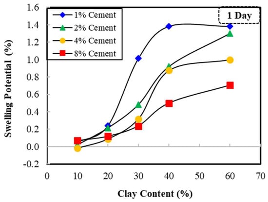
Figure 7.
The swelling potential versus the clay content at 1 day of curing.
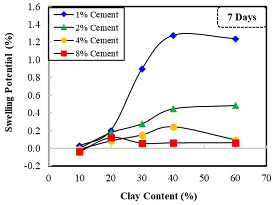
Figure 8.
The swelling potential versus the clay content at 7 days of curing.
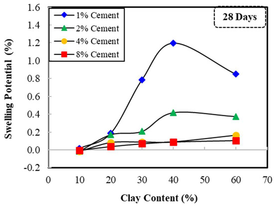
Figure 9.
The swelling potential versus the clay content at 28 days of curing.
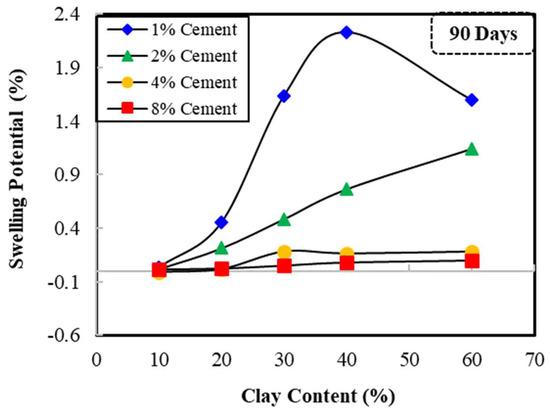
Figure 10.
The swelling potential versus the clay content at 90 days of curing.
Figure 11a–d indicate the curing time for variable amounts of cement additives. The graphs also reflect the clay content influence. It can be observed that at a high cement content (8%) the swelling potential is not changing beyond 10 days of curing time. For 30% clay and beyond, the swelling potential can increase with the increasing curing time.
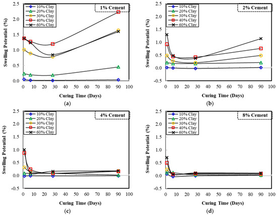
Figure 11.
The swelling potential versus the curing time in days for (a) 1% cement, (b) 2% cement, (c) 4% cement, and (d) 8% cement additives.
The short-term strength increase is mostly due to the hydration reaction, which lowers the mixture’s moisture content and forms the main bonds. On the other hand, the pozzolanic processes start when the pore fluid reaches a specific alkalinity level and an appropriate concentration of hydroxide ions is generated [37,38].
4.5. The Unconfined Compressive Strength
4.5.1. Effect of Clay and Cement Contents
Figure 12a–d present the compressive strength versus the clay content for variable cement contents and curing times. A high strength of 2200 to 3500 kPa is observed for the 8% cement additive. Generally, the compressive strength can decrease for clay contents higher than 30%.
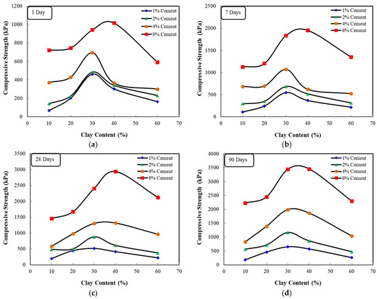
Figure 12.
Compressive strength versus clay content for (a) 1 day of curing, (b) 7 days of curing, (c) 28 days of curing and (d) 90 days of curing at all cement contents.
The variation of the compressive strength of all mixtures with clay contents at all cement content amounts is shown in Figure 12a–d. From these figures, trends of increases in compressive strength with an increase in clay contents were observed up to a clay content of 30%. Beyond this clay content, the trend of compressive strength reverses and the compressive strength decreases with the increase in clay content. This is clearly attributed to the structural arrangements of the sand-expansive clay mixture particles which affect the interaction between different materials. This demonstrates a comparable pattern to the findings of [22,39,40]. When the clay content is small, the clay tends to be confined to the voids of the sand grain skeleton, having very limited contribution to the compressive strength response during shear testing; therefore, the compressive strength behavior is dominated by the sand grains. When the clay content is increased, sand grains are moved apart, and the clay particles fill the sand voids, which leads to stress partitioning and neither the sand nor the clay can play its own role, as they do alone. Therefore, the structural changes and set-up results in changes in the compressive strength. On the other hand, a higher percentage of clay content causes the sand grains to disperse in the fine-grained soils and the compressive strength is wholly governed by the clay material. The observed behavior mirrors that seen with [41,42].
Regarding the effect of cement content, trends of increases in compressive strength with the increase in cement contents are shown for all mixtures. It is noted that with 8% cement and clays of 30% to 40%, a visible peak in compressive strength appears. This is attributed to the high cement content that leads to stronger bonding and improved cohesion between the particles. The increase in cement content results in enhanced hydration reactions, creating a more solidified matrix within the mixture. Similar findings of the increase in compressive strength with the increase in cement content were reported by [43,44,45]. The strength gained due to adding cement is basically due to the solidification of lumps and particles as a result of pozzolanic reactions within the mixtures. Figure 13 demonstrates different views of Al-Qatif pure clay (Figure 13a1,a2) and Al-Qatif clay treated with 2% cement (Figure 13b1,b2) as viewed in SEM images with 2000× (Figure 13a1,b1) and 15,000× (Figure 13a2,b2) magnification. These images of SEM show the particle shape and edge-to-edge contact features of this type of clay [46]. The images show agglomerated particles containing irregularly stacked flat sheets or flakes. These flakes appear in different shapes and sizes under the microscope, with some edges more prominent than others. The most important feature is how flakes are stacked and connected at the edges [47].
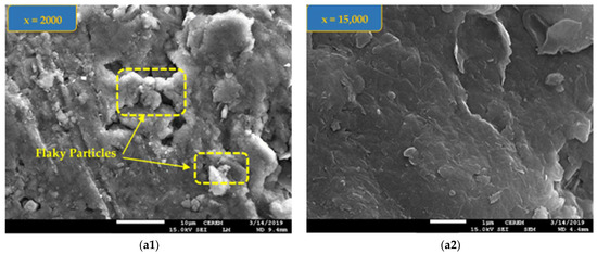
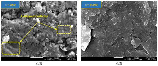
Figure 13.
The SEM images of samples (a1,a2) for Al-Qatif clay, (b1,b2) for Al-Qatif clay with 2% cement.
4.5.2. Effect of the Curing Period for Different Clay Contents
The curing time also plays a crucial role in the strength of mixtures. Cement undergoes a hydration reaction with water, forming a strong binding matrix. Longer curing times allow for a more complete hydration process, resulting in a stronger and more resistant structure with a higher compressive strength.
Figure 14a–d present the effect of the curing period for different clay contents considering each cement additive. The strength is always improving with more time allowed for curing.
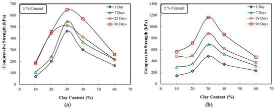
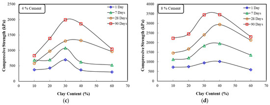
Figure 14.
Effect of curing period for different clay contents with (a) 1% cement, (b) 2% cement, (c) 4% cement, and (d) 8% cement additives.
Ideally, figures depicting this relationship would show a progressive increase in compressive strength with increasing cement contents for all curing times. The rate of this increase might be steeper at early curing times due to the rapid initial hydration process. There could also be a peak strength observed at an optimal clay content, with a decline in strength at both lower and higher clay percentages. Finally, the strength gain would likely be more pronounced for longer curing times across all cement contents. It is important to remember that the specific type of clay and sand used can influence the observed behavior.
5. Conclusions
This research investigated the use of cement-enhanced clay–sand columns in improving foundation practices in expansive soils. The general concept of this approach is to bring down the contact pressure to a lower foundation level to reduce the uplift pressure. The study surveyed the effect of adding 1, 2, 4 and 8% cement to clay–sand mixtures made up of expansive soil. Combinations of sand and clay in which 10%, 20%, 30%, 40% and 60% expansive Al-Qatif clay was added to sand were investigated. The compressibility, swelling potential and compressive strength were all examined for curing periods varying from 1 day to 90 days. The study presents graphs for all variables that may affect the design of cement-enhanced clay–sand columns. The general geometry of the columns is suggested with alternatives of using one bulk shaft or multiple columns. A tapered system may be used to increase contact pressure at the founding level, if required. It was found that a maximum of 30% clay can be used in order to increase the compressive strength, and reduce the swelling potential and compressibility. Guidelines for curing times are suggested to enable timely controlled construction after completing the cement-enhanced columns. The wait for hydration to be completed might take longer amounts of time before construction can start. To overcome this problem, future research may consider some additives that can help in solidifying the mixture in shorter times.
Author Contributions
Conceptualization, A.A.S. and M.D.; methodology, A.A.S.; formal analysis, A.A.S. and M.D.; investigation, A.A.S.; resources; A.A.S.; writing—original draft, A.A.S. and M.D.; writing—review and editing, M.D.; review, editing, and supervision, A.A.S. and M.D.; funding acquisition, M.D. All authors have read and agreed to the published version of the manuscript.
Funding
This article is funded by the Researchers Supporting Project of King Saud University, Riyadh, Saudi Arabia. Project number RSPD2024R1059.
Institutional Review Board Statement
Not applicable.
Informed Consent Statement
Not applicable.
Data Availability Statement
The data that support the findings of this study are available from the corresponding author upon reasonable request.
Acknowledgments
The authors gratefully acknowledge the Researchers Supporting Project number RSPD2024R1059, King Saud University, Riyadh, Saudi Arabia, for their financial support for the research work reported in this article.
Conflicts of Interest
The authors declare that they have no conflicts of interest.
Nomenclature
| CH | Clay with high plasticity |
| Q | AL-Qatif expansive clay |
| OMC | Optimum moisture content |
| ℽdmax | Maximum dry unit weight |
| Cc | Compression index |
| Cr | Rebound index |
| UCS | Unconfined compressive strength |
| SP | Swelling potential |
References
- Jones, L.D.; Jefferson, I. Expansive soils. In ICE Manual of Geotechnical Engineering. Volume 1, Geotechnical Engineering Principles, Problematic Soils and Site Investigation; ICE Publishing: London, UK, 2012; Volume 1, pp. 413–441. [Google Scholar]
- Miura, N.; Yamadera, A.; Hino, T. Consideration on compression properties of m clay based on the pore size distribution measurement. Doboku Gakkai Ronbunshu 1999, 1999, 203–215. [Google Scholar] [CrossRef][Green Version]
- Miura, N.; Horpibulsuk, S.; Nagaraj, T.S. Engineering behavior of cement stabilized clay at high water content. Soils Found. 2001, 41, 33–45. [Google Scholar] [CrossRef]
- Horpibulsuk, S.; Bergado, D.T.; Lorenzo, G.A. Compressibility of cement-admixed clays at high water content. Geotechnique 2004, 54, 151–154. [Google Scholar] [CrossRef]
- Horpibulsk, S.; Rachan, R.; Suddeepong, A.; Chinkulkijniwat, A. Strength development in cement admixed Bangkok clay: Laboratory and field investigations. Soils Found. 2011, 51, 239–251. [Google Scholar] [CrossRef]
- Khemissa, M.; Mahamedi, A. Cement and lime mixture stabilization of an expansive overconsolidated clay. Appl. Clay Sci. 2014, 95, 104–110. [Google Scholar] [CrossRef]
- Goodarzi, A.R.; Akbari, H.R.; Salimi, M. Enhanced stabilization of highly expansive clays by mixing cement and silica fume. Appl. Clay Sci. 2016, 132, 675–684. [Google Scholar] [CrossRef]
- Shafiee, A. Permeability of compacted granule-clay mixtures. Eng. Geol. 2008, 97, 199–208. [Google Scholar] [CrossRef]
- Mitchell, J.K.; Soga, K. Fundamentals of Soil Behavior; John Wiley & Sons: New York, NY, USA, 2005; Volume 3. [Google Scholar]
- Al-Rawas, A.A.; Mohamedzein, Y.E.A.; Al-Shabibi, A.S.; Al-Katheiri, S. Sand–attapulgite clay mixtures as a landfill liner. Geotech. Geol. Eng. 2006, 24, 1365–1383. [Google Scholar] [CrossRef]
- Azam, S. Study on the swelling behaviour of blended clay–sand soils. Geotech. Geol. Eng. 2007, 25, 369–381. [Google Scholar] [CrossRef]
- Obrike, S.E.; Osadebe, C.C.; Omoniyi, S.S. Geotechnical analysis of two Nigerian soils for use as clay liners. Bull. Eng. Geol. Environ. 2009, 68, 417–419. [Google Scholar] [CrossRef]
- Pratibha, P.; Ameta, N.K. Experimental investigation of compaction and hydraulic conductivity characteristics of dune sand–Clay mixture from thar desert. Electron. J. Geotech. Eng. 2013, 18, 2645–2651. [Google Scholar]
- Shaker, A.; Dafalla, M.; Al-Shamrani, M. Effect of Cement on Compressibility and Swell of Sand-Expansive Clay Mixtures. Geomate J. 2020, 19, 100–106. [Google Scholar] [CrossRef]
- Chen, Y.; Zhou, Y.; Kong, G.; Chen, L.; Chen, G. Settlement and stress analysis of soil–cement column-reinforced foundation under an in situ stabilized layer. Int. J. Geomech. 2021, 21, 6021032. [Google Scholar] [CrossRef]
- Wang, J.; Xie, J.; Wu, Y.; Wang, C.; Liang, F. An investigation of the effect of utilizing solidified soil as scour protection for offshore wind turbine foundations via a simplified scour resistance test. J. Mar. Sci. Eng. 2022, 10, 1317. [Google Scholar] [CrossRef]
- Wang, C.; Wu, Q.; Zhang, H.; Liang, F. Effect of scour remediation by solidified soil on lateral response of monopile supporting offshore wind turbines using numerical model. Appl. Ocean Res. 2024, 150, 104143. [Google Scholar] [CrossRef]
- Ahmad, R. Engineering Properties and Mineralogical Composition of Expansive Clays in Al-Qatif Area (KSA). Master’s Thesis, King Fahd University of Petroleum and Minerals, Dhahran, Saudi Arabia, 1988. [Google Scholar]
- Abduljauwad, S.N. Characteristics and chemical treatment of expansive clay in Al-Qatif, Saudi Arabia. Eng. Geol. 1991, 31, 143–158. [Google Scholar] [CrossRef]
- Al-Shayea, N.A. The combined effect of clay and moisture content on the behavior of remolded unsaturated soils. Eng. Geol. 2001, 62, 319–342. [Google Scholar] [CrossRef]
- Azam, S. Influence of mineralogy on swelling and consolidation of soils in eastern Saudi Arabia. Can. Geotech. J. 2003, 40, 964–975. [Google Scholar] [CrossRef]
- Elkady, T.Y.; Shaker, A.A.; Dhowain, A.W. Shear strengths and volume changes of sand–attapulgite clay mixtures. Bull. Eng. Geol. Environ. 2015, 74, 595–609. [Google Scholar] [CrossRef]
- Shaker, A.A.; Elkady, T.Y. Hydraulic performance of sand–clay mixtures: Soil fabric perspective. Géotech. Lett. 2015, 5, 198–204. [Google Scholar] [CrossRef]
- Dafalla, M.A. The Compressibility and Swell of Mixtures for Sand-Clay Liners. Adv. Mater. Sci. Eng. 2017, 2017, 3181794. [Google Scholar] [CrossRef]
- ASTM:D 854; Standard Test Methods for Specific Gravity of Soil Solids by Water Pycnometer. ASTM International: West Conshohocken, PA, USA, 2000; pp. 1–7.
- ASTM:D 2487; Standard Practice for Classification of Soils for Engineering Purposes (Unified Soil Classification System). ASTM International: West Conshohocken, PA, USA, 2000; pp. 249–260.
- ASTM:D 4318; Standard Test Methods for Liquid Limit, Plastic Limit, and Plasticity Index of Soils. ASTM International: West Conshohocken, PA, USA, 2000; pp. 1–14.
- ASTM:D 4546; Standard Test Methods for One-Dimensional Swell or Settlement Potential of Cohesive. ASTM International: West Conshohocken, PA, USA, 2003; Volume 3, pp. 1–9.
- ASTM: D 698; Standard Test Methods for Laboratory Compaction Characteristics of Soil Using Standard Effort (12, 400 ft-lbf/ft 3 (600 kN-m/m3)). ASTM International: West Conshohocken, PA, USA, 2003; Volume 3, pp. 1–11.
- ASTM:D 5102; Standard Test Method for Uncon ned Compressive Strength of Compacted Soil-Lime Mixtures. ASTM International: West Conshohocken, PA, USA, 2004; Volume 4, pp. 1–6.
- ASTM:D 2166; Standard Test Method for Unconfined Compressive Strength of Cohesive Soil. ASTM International: West Conshohocken, PA, USA, 2013; Volume 4, pp. 1–7.
- A Rashid, A.S.; Bunawan, A.R.; Mat Said, K.N. The deep mixing method: Bearing capacity studies. Geotech. Geol. Eng. 2017, 35, 1271–1298. [Google Scholar] [CrossRef]
- Alhamdi, M.K.; Albusoda, B.S. A Review on Deep mixing method for soil improvement. In Proceedings of the IOP Conference Series: Materials Science and Engineering, Andhra Pradesh, India, 7–8 May 2021; IOP Publishing: Bristol, UK, 2021; Volume 1105, p. 12110. [Google Scholar]
- Abas, H.A.; Alluqmani, A.E.; Yousif, I. Assessing deep soil mixing for excavation support in Sabkha soils: A numerical study. J. Umm Al Qura Univ. Eng. Archit. 2024, 15, 1–13. [Google Scholar] [CrossRef]
- Al-Qaisi, M.S.; Al-Waily, M.J.M. Experimental Study of Soft Clay Soil Improvement by Deep Mixing Method. Math. Model. Eng. Probl. 2022, 9, 224–232. [Google Scholar] [CrossRef]
- Puppala, A.J.; Pedarla, A. Innovative ground improvement techniques for expansive soils. Innov. Infrastruct. Solut. 2017, 2, 1–15. [Google Scholar] [CrossRef]
- Herzog, A.; Mitchell, J.K. Reactions accompanying stabilization of clay with cement. Highw. Res. Rec. 1963, 36, 146–171. [Google Scholar]
- Xiao, H.W.; Lee, F.H. Curing time effect on behavior of cement treated marine clay. Int. J. Mar. Environ. Sci. 2008, 2, 144–151. [Google Scholar]
- Kim, D.; Nam, B.H.; Youn, H. Effect of clay content on the shear strength of clay–sand mixture. Int. J. Geo Eng. 2018, 9, 19. [Google Scholar] [CrossRef]
- Miftah, A.; Garoushi, A.H.B.; Bilsel, H. Effects of fine content on undrained shear response of sand–clay mixture. Int. J. Geosynth. Gr. Eng. 2020, 6, 10. [Google Scholar] [CrossRef]
- Dafalla, M.A. Effects of clay and moisture content on direct shear tests for clay-sand mixtures. Adv. Mater. Sci. Eng. 2013, 2013, 562726. [Google Scholar] [CrossRef]
- Dafalla, M.; Shaker, A.; Elkady, T.; Almajed, A.; Al-Shamrani, M. Shear strength characteristics of a sand clay liner. Sci. Rep. 2020, 10, 18226. [Google Scholar] [CrossRef] [PubMed]
- Boutouba, K.; Benessalah, I.; Arab, A.; Henni, A.D. Shear strength enhancement of cemented reinforced sand: Role of cement content on the macro-mechanical behavior. Stud. Geotech. Mech. 2019, 41, 200–211. [Google Scholar] [CrossRef]
- Nguyen, T.T.; Nguyen, M.D.; Nguyen, T.; Phan, T.C. Interface shear strength behavior of cement-treated soil under consolidated drained conditions. Buildings 2023, 13, 1626. [Google Scholar] [CrossRef]
- Bayoumy, M.; El Sawwaf, M.; Nasr, A.; Elsawwaf, A. Strength characteristics of clayey sand stabilized using polypropylene fiber or Portland cement. Transp. Infrastruct. Geotechnol. 2024, 11, 1249–1271. [Google Scholar] [CrossRef]
- Almajed, A.; Dafalla, M.; Shaker, A.A. The Combined Effect of Calcium Chloride and Cement on Expansive Soil Materials. Appl. Sci. 2023, 13, 4811. [Google Scholar] [CrossRef]
- Thamer, B.M.; Shaker, A.A.; Hameed, M.M.A.; Al-Enizi, A.M. Highly selective and reusable nanoadsorbent based on expansive clay-incorporated polymeric nanofibers for cationic dye adsorption in single and binary systems. J. Water Process Eng. 2023, 54, 103918. [Google Scholar] [CrossRef]


Disclaimer/Publisher’s Note: The statements, opinions and data contained in all publications are solely those of the individual author(s) and contributor(s) and not of MDPI and/or the editor(s). MDPI and/or the editor(s) disclaim responsibility for any injury to people or property resulting from any ideas, methods, instructions or products referred to in the content. |
© 2024 by the authors. Licensee MDPI, Basel, Switzerland. This article is an open access article distributed under the terms and conditions of the Creative Commons Attribution (CC BY) license (https://creativecommons.org/licenses/by/4.0/).