Article

Study on the Effects of Influence Factors on the Stress and Deformation Characteristics of Ultra-High CFRDs

1
College of Hydraulic and Civil Engineering, Xinjiang Agricultural University, Urumqi 830052, China
2
Xinjiang Key Laboratory of Hydraulic Engineering Security and Water Disasters Prevention, Xinjiang Agricultural University, Urumqi 830052, China
*
Author to whom correspondence should be addressed.
Appl. Sci. 2024, 14(18), 8268; https://doi.org/10.3390/app14188268
Submission received: 14 August 2024 / Revised: 10 September 2024 / Accepted: 11 September 2024 / Published: 13 September 2024

Abstract

:
A sensitivity analysis was conducted to evaluate several factors, including dam height, bank slope gradient, water storage times, and phased panel filling, on concrete-faced rockfill dams (CFRDs). The analysis identified the three most significant factors to examine their impacts on the stress-deformation characteristics of CFRDs. The results show that the order of influence on the dam body’s stress and deformation characteristics is as follows: dam height > bank slope gradient > water storage times > panel phased construction. From the perspective of stress-deformation of the face slab, water storage times predominantly affect tensile stress, while the bank slope gradient exerts the greatest influence on compressive stress. As the bank slope gradient decreases, the panel’s lateral restraint diminishes, leading to a decrease in the panel’s extrusion efficacy. Consequently, there are notable variations in the panel’s compressive stresses. An increase in dam height correlates with escalating stress and deformation in both the dam and face slab. As the bank slope gradient decreases, the deformation of the dam and face slab, as well as the range of tensile stress of the face slab, also increase. In contrast to a single water storage scenario, the face slab has experienced greater stress and deformation during the initial impoundment under multiple impoundment conditions. Therefore, multiple water storage schemes result in reduced deflection, axial horizontal displacement, and tensile stresses both along the slope and axial in the face slab. Furthermore, the tensile area at the bottom of the face slab transitions into a compressive area.

1. Introduction

Concrete-faced rockfill dams (CFRDs) are widely used in the dam industry owing to their numerous advantages [1,2]. Since the introduction of CFRDs in China, significant progress has been made in both the number of dam constructions and the height of these dams. Over 400 CFRDs have been built and are under construction in China, and the design height of a considerable number of dams is being challenged toward the 300 m mark.
Currently, among the CFRDs that have been constructed or are in progress, both domestically and internationally, some have experienced significant non-uniform deformation during the completion or operational phases. This deformation can lead to cracks in the face slab, separation between the face slab and the cushion layer, and compression damage at the vertical joints of the face slab [3]. These issues may result in excessive leakage or even collapse of the dam body [4,5], leading to serious loss of life and property. For instance, the Campos Novos CFRD in Brazil suffered hollowness in the face slab, causing cracks at the vertical joints and severe concrete spalling [6,7]; the Xibeikou CFRD faced severe face slab cracking; the Gouhou concrete-faced gravel dam collapsed; the Zhushuqiao CFRD encountered water leakage due to face slab fractures and sealing structure damage; and during the initial stages of the Tianshengqiao concrete-faced rockfill dam, cracks and voids appeared in the face slab and cushion layers, accompanied by compression damage at the vertical joints. All these problems are associated with excessive deformation of the dam. With the continuing advancement of the water conservancy industry and construction technology, the height of faced rockfill dams has surpassed 200 m. Consequently, conducting stress and deformation analysis on CFRDs is of paramount importance [8]. This is especially true for ultra-high CFRDs, where accurate predictions of their stress and deformation status can help in applying preventive measures to control these issues, thereby ensuring the safety of the dams and protecting lives and property.
The stress and deformation characteristics of CFRDs are influenced by various factors, such as dam height, water storage, valley terrain, phased panel filling, and temperature. The influence of various factors on the stress and deformation characteristics of CFRDs varies. Extensive research has been conducted on these influencing factors. This study compiled data on numerous CFRDs under construction and in operation, incorporating trait monitoring and finite element analysis data into the dataset; some of this information is indicated in Table 1. Figure 1 illustrates the statistical patterns of the maximum internal settlement of the dam and the maximum deflection of the face slabs in relation to the dam height under different operational conditions. It is evident from Figure 1 that the variation in dam height results in a maximum settlement of the dam body being predominantly controlled within 1.0% of the dam height. However, for some dams (Tianshengqiao and BaKun), the maximum settlement of the dam body approaches approximately 1.8%. For high dams, the deformation of individual projects has exceeded 1.0%, which can lead to cracks in the face panel. Ultra-high CFRDs, in particular, exhibited unfavorable deformation characteristics when the dam height was excessive. This is attributed to the pronounced particle breakage within the rockfill body under high-stress conditions, leading to reduced strength, considerable dam body deformation, and, consequently, significant cracks and voids in the face slab. Figure 1b reveals that the maximum deflection of the face slab during the water storage period was substantially greater than during the completion period, highlighting the profound impact of the water storage process on the stress and deformation characteristics of the face slab. However, in actual engineering, water storage is carried out multiple times to reach the normal water storage level, and the number of water storage times can also have a certain impact on the stress and deformation of the panel, which is worthy of further research. The bank slope gradients of the dams are compiled in Table 1. The topography of each dam’s valley varies, consisting of wide and narrow valleys. The former has less constraint on the dam body, while the latter imposes a stricter constraint. However, there may be increased shear slip and deformation gradient between the dam body and the foundation in narrow valleys, which is unfavorable for the deformation control of the panel. Furthermore, the river valley’s bank slope comprises both steep and gentle slopes. When the river valley slope is steep, a stress arch effect is likely to occur in the dam body, hindering deformation control. Additionally, there are symmetrical and asymmetrical conditions on the bank slope, and these variations on the valley’s bank slope have a notable impact on the stress and deformation of the panel, necessitating further investigation. Given that the panel construction is not filled to the dam crest all at once during actual construction, phased construction of the panel directly influences the stress and deformation of the panel. Therefore, phased construction of the panel is considered as one of the influencing factors. The temperature of the concrete can significantly influence the stress and deformation characteristics of the dam. An elevated internal temperature, coupled with an uneven distribution of hydration products, may result in an increase in internal pores, a reduction in structural strength, and an enhanced likelihood of the development of internal microcracks and thermal cracks. Such phenomena can substantially affect the stress state of the overall structure of the concrete. In light of the foregoing considerations, numerous factors contribute to the stress and deformation characteristics of CFRDs. This study selects dam height, bank slope gradient, water storage process, and the staged construction of the panel as influencing factors; performs sensitivity analysis; and investigates the general principles of stress and deformation.
Previous studies examining factors influencing stress and deformation in medium and high CFRDs primarily conducted qualitative analyses, often lacking in quantitative assessments of each factor’s degree of influence or sensitivity analysis. To address this gap, it is imperative to investigate the stress and deformation properties of ultra-high CFRDs and their influencing factors. Reviewing the extant literature through the lens of stress and deformation, this study aims to examine the sensitivity of key factors to the stress and deformation characteristics of ultra-high dam bodies and panels, quantitatively delving into the significance of different influencing factors on the stress and deformation characteristics of the dam and panel. Additionally, this study investigated the overarching impact of the three most influential factors on the stress and deformation of both the dam and panel. This study amalgamates ABAQUS and a projection pursuit regression (PPR) technique to quantitatively delve into and critique the significance of various influencing variables on the stress and deformation attributes of CFRDs. Furthermore, it examines the generalized stress and deformation regulations attendant upon variations in these influencing factors. It offers comprehensive direction for the design, construction, supervision, and preservation of ultra-high dam engineering, thereby enhancing the security and dependability of the project.

2. Projection Pursuit Regression Model

Projection pursuit regression (PPR) is a data analysis technique designed for multivariate data, aimed at uncovering the data’s structural features by reducing the dimensionality of the data. In this regression method, the data undergo preprocessing initially, followed by determination of the optimal projection direction, which is achieved by maximizing certain statistics of the projection data. The regression model is then constructed on this projection direction to facilitate the transformation of high-dimensional data into low-dimensional data. This approach eliminates the need for artificial assumptions, allowing for a more objective representation of the essential characteristics of the data. It is particularly adept at elucidating the dependency relationships between independent and dependent variables in the multi-parameter, nonlinear, and linear systems characteristic of high-dimensional data [13,14].
The PPR model is represented by Equation (1) [13,14,15,16,17,18,19]:
F ( x ) = E ( y i | x 1 , x 2 , , x p ) = y i ¯ + j = 1 M β j l j ( k = 1 P α j k x k )
where x k denotes the kth independent variable, y i represents the i th dependent variable, F ( x ) is the regression function of y i based on P independent variables, y i ¯ is the mean of the nth observation of the ith dependent variable, l j represents the jth ridge function that satisfies E l j = 0 and El j 2 = 1 , M expresses the upper limit number of the explored ridge functions, β j denotes the weight coefficient of the jth ridge function, and α j k is the kth component in the jth projection direction that satisfies the equation j = 1 P α j k 2 = 1 .
The constraint conditions are represented by Equation (2) and must satisfy the minimization criterion [13,14,15,16,17,18,19].
L 2 = i = 1 Q W i E ( y i y i ¯ ) j = 1 M U β j l j ( K = 1 P α j k x k ) 2 = m i n
where M U denotes the number of optimal ridge functions, W i is the dependent variable weight coefficient, and the remaining parameters are the same as those in Equation (1).
In the regression model, the coefficient of each independent variable can be interpreted as the contribution weight of the variable in the projection direction. In the aforementioned formula, β j represents the relative contribution weight required, which enables us to discern the relative significance of each independent variable to the change in the dependent variable. These weights can assist us in identifying the crucial factors within the individual independent variables and facilitate further data analysis and decision-making.

3. Sensitivity Analysis of Influencing Factors on Stress and Deformation of CFRDs

3.1. Calculation Scheme

For this study, dam height, bank slope gradient, water storage process, and panel phased construction were selected as influencing factors. The dam heights considered were 200 m, 250 m, and 300 m. The bank slope gradients were set at 1:0.5, 1:1, and 1:1.5, respectively. Water storage was loaded in 1, 2, or 3 times, and the construction of the face slab was completed in 1, 2, or 3 stages, reaching up to the dam crest. The design of the calculation scheme, informed by the orthogonal experimental method [20], is presented in Table 2. The following calculation scheme takes into account various intersections of the above four factors. The finite element model was employed to calculate and subsequently compare the results, including the maximum internal settlement of the dam body, horizontal displacement along the river, horizontal displacement along the dam axis, maximum deflection of the face slab, as well as the tensile and compressive stresses both along the river and the dam axis under the various scenarios. Utilizing the results from the finite element numerical calculations, projection pursuit regression (PPR) statistical inference technology was applied to deduce the relative weight contribution values of the four influencing factors. This process enabled a quantitative analysis of the relationship between each influencing factor and the characteristic values of CFRDs.

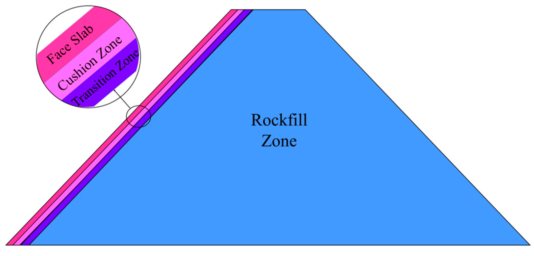
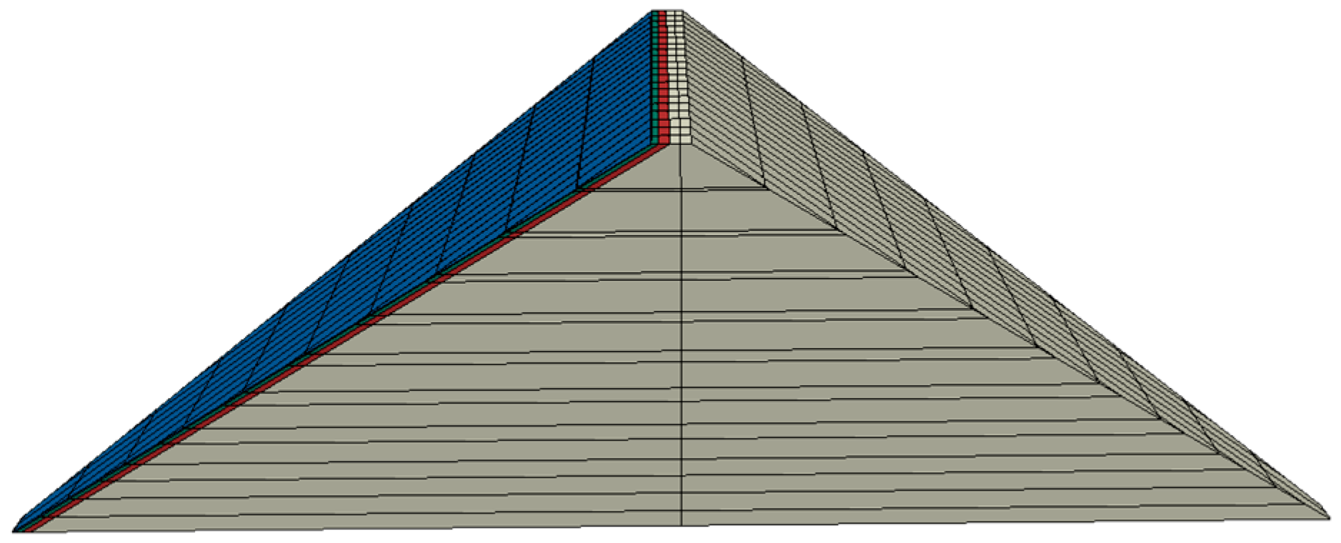
3.2. Finite Element Model

3.2.1. Geometric Model

The characteristics of the calculation and analysis model for the concrete-faced rockfill dam are delineated as follows: the dam is segmented into the concrete face slab, cushion layer, transition layer, and rockfill zone. The crest width of the dam measures 10 m, the thickness of the face slab is 0.5 m, the cushion layer has a horizontal width of 2 m, the transition zone extends 3 m horizontally, and the downstream face of the dam has a slope of 1:1.4. The valley is symmetrical, and the reservoir’s water level reaches up to 10 m below the crest of the dam. The coordinate system for the calculations is defined with the X-axis along the dam axis, positive towards the right bank; the Y-axis extends along the river, with the positive direction pointing downstream; and the Z-axis is vertical, with the positive direction upwards. The sign convention for the calculation results is standardized: settlement is positive when upwards and negative when downwards; horizontal displacement is considered positive when moving downstream and negative when moving upstream; deflection is positive when facing upwards in the normal direction of the face slab and negative when facing downwards; and stress is regarded as positive under tension and negative under compression.
The model’s components are predominantly fashioned from the eight-node spatial hexahedral element, albeit incorporating a minor subset of the three-prism six-node element type within the ABAQUS (6.14) finite element software. Taking the 250 m high typical 3D concrete-faced rockfill dam with the fifth calculation scheme as an example, the standard cross-section is depicted in Figure 2 and the 3D finite element model is illustrated in Figure 3. The computational boundary conditions entail fixing the base surface of the dam and the lateral margins of the left and right bank slopes, with the remainder of the domain being governed by a free boundary condition.

3.2.2. Calculation Parameters

The Duncan Chang E-B model, formulated by Duncan et al., is the most commonly adopted model when characterizing rockfill behavior in construction [21,22,23]. This nonlinear elastic model was applied to the dam-filling material, while a linear elastic model was utilized for the concrete face slab. The static model parameters for the rockfill material are presented in Table 3. The concrete’s elastic modulus is set at 28 MPa, Poisson’s ratio at 0.167, and density at 2.5 g/cm3.

3.3. Sensitivity Analysis of Factors Affecting Stress and Deformation

Table 4 and Table 5 display the relative weight contribution values of the influencing factors on the characteristics of the dam and panel, as calculated using projection pursuit regression technology. Among them, F1, F2, F3, and F4 represent the influencing factors of dam height, bank slope gradient, panel phased construction, and water storage, respectively. Figure 4 and Figure 5 are plotted based on the values calculated for the storage period.
Taking dam settlement during the impinging period as an example, the relative influence weights of dam height, bank slope gradient, panel phased construction, and storage on dam settlement are 1.000, 0.439, 0.014, and 0.025, respectively. In other words, the sensitivity of each influencing factor to dam settlement during the storage period ranges from strong to weak, as follows: dam height > bank slope gradient > water storage > panel phased construction. Similarly, it can be observed from Table 4 and Figure 4 that the sensitivity of each influencing factor to dam body settlement, river displacement, and dam axial displacement remains consistent, regardless of completion period or water storage period.
Furthermore, based on relative contribution weight and using panel deflection as an example, the relative influence weights of dam height, bank slope gradient, water storage, and panel phased construction on panel deflection are 1.000, 0.352, 0.115, and 0.154, respectively. In this case, the sensitivity of influencing factors on panel deflection during the water storage period also ranges from strong to weak: dam height > bank slope gradient > panel phased construction > water storage. Similarly, as depicted in Table 5 and Figure 5, the sensitivity of the aforementioned factors to the axial horizontal displacement of the panel is as follows: dam height > bank slope gradient > panel phased construction > water storage. As for the sensitivity of influencing factors to tensile stress along the slope and axial, the ranking is as follows: water storage > bank slope > dam height gradient > panel phased construction. Under conditions of multiple water impacts, the panel endures considerable stress and deformation during the initial collision. With the increase in subsequent impingement times, the panel’s deformation and tensile stress are mitigated, and the tension area of some parts of the panel is transformed into a compression area. This evidence suggests that water storage exerts a profound influence on the panel’s tensile stress. Regarding sensitivity to axial compressive stress, the ranking is as follows: bank slope gradient > dam height > water storage > panel phased construction. Finally, sensitivity to compressive stress along the slope is ranked as follows: bank slope gradient > dam height > panel phased construction > water storage. As the bank slope gradient intensifies, the panel’s lateral restraint diminishes, leading to a decrease in the panel’s extrusion efficacy. Consequently, there is a notable reduction in the panel’s compressive stresses.

4. Research on Stress and Deformation Characteristics of CFRDs under Different Factors

4.1. Calculation Scheme

Based on the sensitivity analysis of factors influencing the stress and deformation of CFRDs, it was determined that dam height, bank slope gradient, and water storage are the most influential factors, ranking as the top three in the comprehensive impact degree of the four factors considered. Consequently, these three factors were selected for further analysis, and a total of three calculation schemes were developed. The specifics of each calculation scheme are provided in Table 6. According to the data in Table 7, the characteristic values of the dam and face slab during the storage period for each calculation scheme are shown.

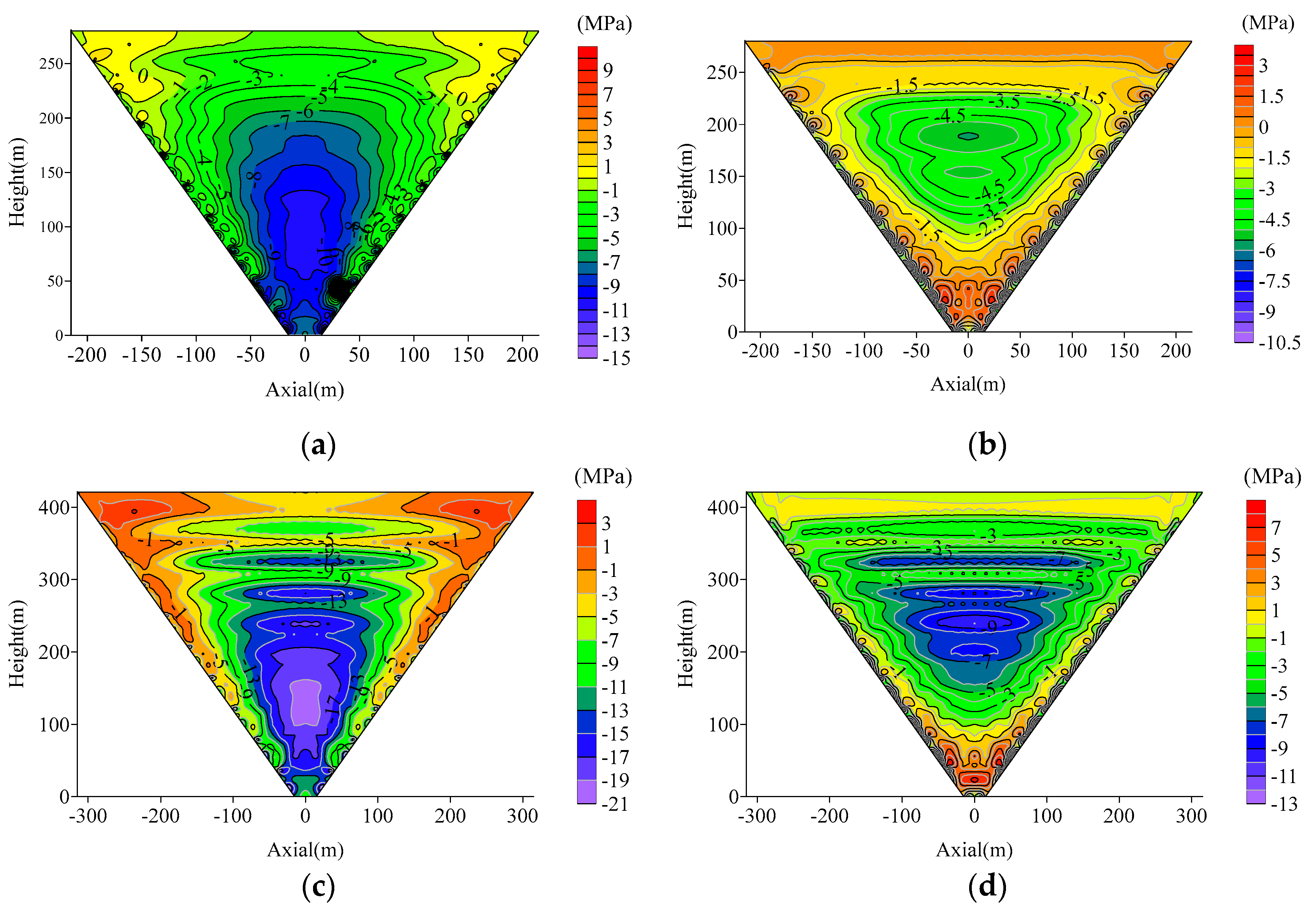
4.2. The Influence of Dam Height on the Stress and Deformation of CFRDs

The results from the first set of schemes in Table 7 indicate that the stress and deformation characteristics of the dam and the deformation characteristics of the face slab increased with the rise in dam height. For each incremental rise in dam height, the deformation of both the dam body and face slab was augmented by approximately 30% to 50%. This demonstrates that dam height significantly affects the deformation characteristics of the dam and face slab.
Figure 6 illustrates the changes and distribution of dam internal settlement, panel deflection, panel stress along the slope, and axial direction throughout the water storage period, as related to the dam or panel height. The findings revealed that the peak internal settlement of the dam at varying heights typically occurred between 1/3 to 1/2 of the dam height from the top. The maximum deflection values were generally located at 75% of the panel height. The majority of the panel areas along the slope direction, primarily the middle and upper portions, experienced compressive stress, while localized zones (including around the panel shoulder and bottom, and along the local coastal slope) were subjected to tensile stress. The peak compressive stress appeared between 1/3 and 1/2 of the panel height from the top, and the maximum tensile stress was consistently found below 10% of the face slab height. The panel’s axial direction was predominantly under compression, with the maximum compressive stress typically centered in the center of the valley, at approximately 20% of the face slab height. Figure 7 depicts the stress distribution along the slope and axial direction on the face slab during the water storage period under various dam heights. By integrating the observations from Figure 6 and Figure 7, it was evident that the range of tensile stress distribution in the face slab along the slope and axial direction expanded with an increase in dam height, which conforms to the general rule. In the actual project, to address the issue of increased tensile stress in the face slab due to the height of the dam, a multitude of strategies have been implemented, including employing judicious filling processes and pre-compaction measures to curtail the uneven deformation of the dam structure; and refining the spacing between panels and the design of vertical seams to accommodate the axial extrusion deformations experienced by the panels.

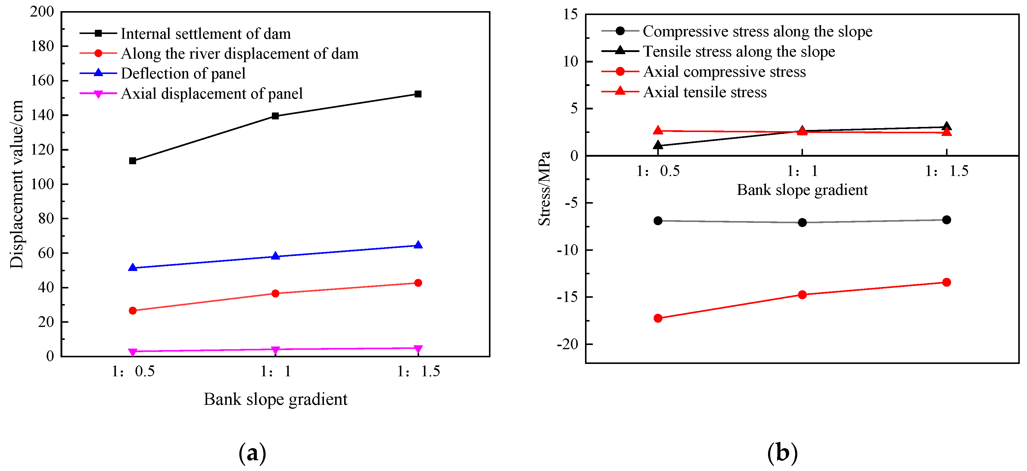
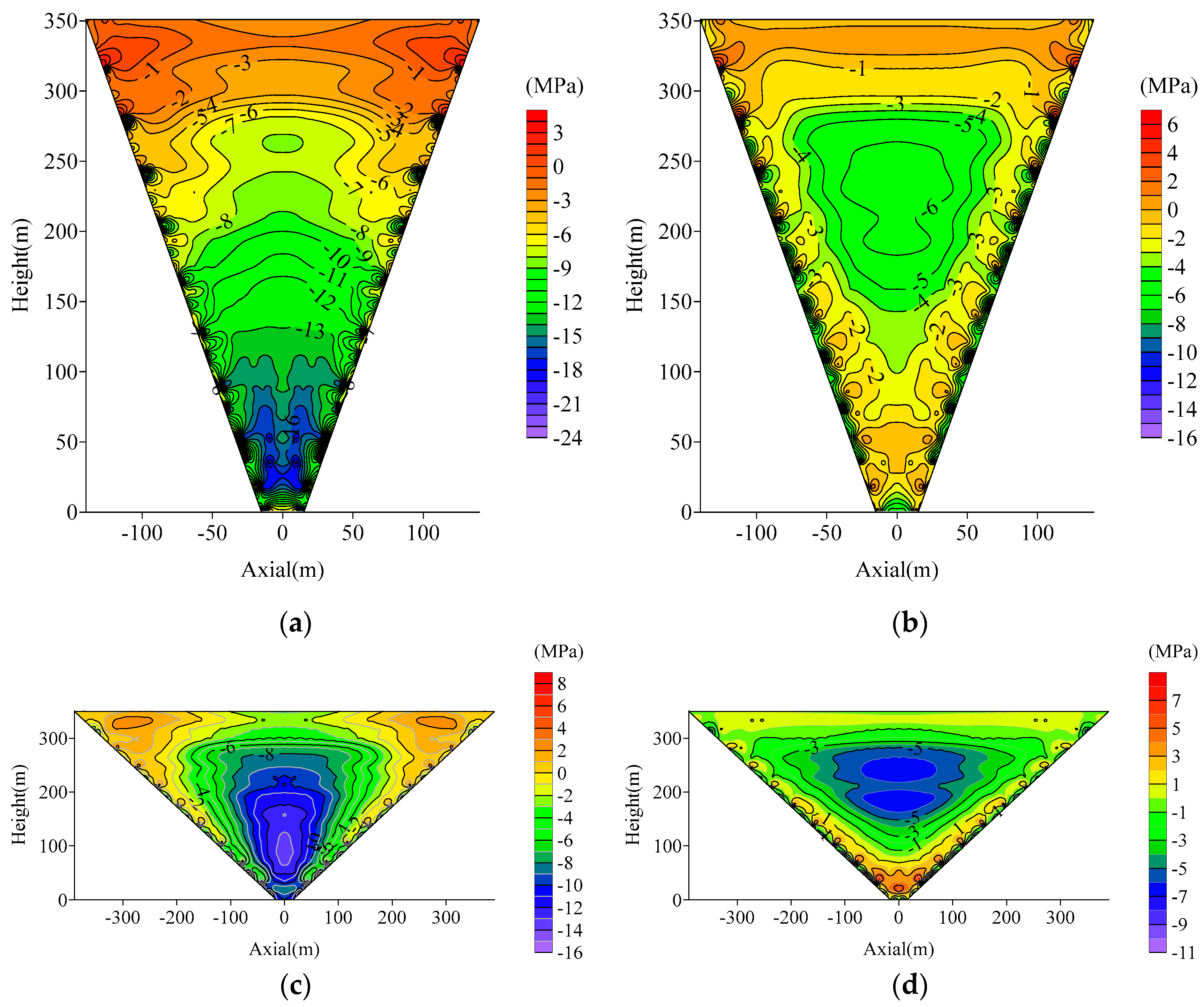
4.3. The Influence of Bank Slope Gradient on the Stress and Deformation of CFRDs

The stress and deformation characteristics of the dam and panel under varying bank slope gradient conditions during the water storage period are presented in Figure 8. It was observed that the stress and deformation characteristics of the dam and panel both increased as the bank slope gradient became less steep. Specifically, the compressive stress along the slope of the panel gradually diminished with a gentler bank slope gradient, whereas the tensile stress conversely increased. This phenomenon occurs because as the slope gradient eases, the lateral constraints on the dam provided by the banks decrease, resulting in greater deformation of the dam and an associated increase in tensile stress along the slope of the face slab. An increase in tensile stress may result in the development of cracks within the panel. This is particularly true when the applied stress surpasses the tensile capacity of the concrete, causing the existing cracks to propagate and subsequently compromise the dam’s seepage control capabilities. Moreover, such tensile stress variations can induce alterations in the internal stress distribution within the structure, thereby impacting the stress conditions of other structural elements. Furthermore, the axial stress of the panel progressively decreased as the bank slope gradient became more gradual. This trend is attributable to the diminishing compressive effect exerted on the panel by the banks as the slope gradient lessens, leading to a reduction in axial stress.
The distribution area of the maximum characteristic values of the dam and panel along the height direction was found to be generally consistent with the corresponding area under different dam heights, as previously described. Figure 9 illustrates the distribution of stress along the slope and axial direction when the bank slope gradients are 1:0.5 and 1:1.5. From this figure, it was concluded that with a steeper slope, the extent of the tensile stress zone along the slope direction at the bank slope is relatively small. As the bank slope gradient becomes gentler, the range of the tensile stress zone along the slope direction at the bottom of the panel and at the dam shoulders on both banks progressively enlarges. In terms of stress along the axial direction, when the bank slope gradient is steep, the tensile stress zone of the panel is predominantly localized at the dam shoulders on both sides. Conversely, as the bank slope gradient decreases, the panel tensile stress zone broadens, extending from the dam shoulders on both sides towards the center of the valley and advancing downward along the slope direction of the bank towards the lower part of the panel.

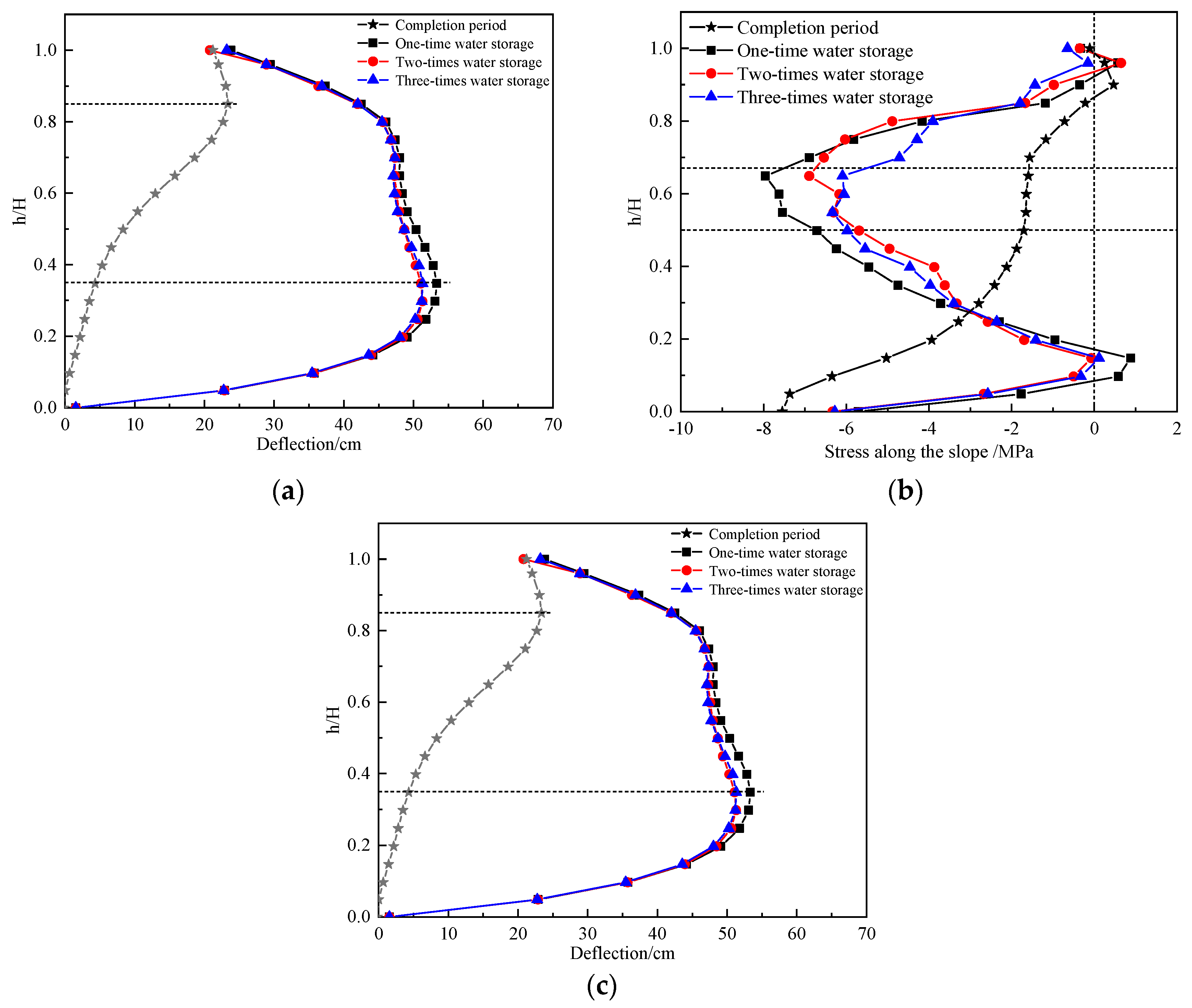
4.4. The Influence of Water Storage on the Stress and Deformation of CFRDs

The influence of water storage on stress and deformation characteristics exhibited a marked difference between the completion period and storage period conditions. Therefore, when examining the impact of water storage on the stress and deformation of CFRDs, it is essential to consider both the completion period and the storage period. Drawing from the calculation and sensitivity analysis results of the third set of schemes in Table 7, the effect of water storage on the stress and deformation characteristics of the dam body was found to be insignificant; thus, the discussion focuses solely on the influence on the panel. It was noted that compared to a single water storage event, deflection, axial horizontal displacement, and tensile stress along both the slope and axial directions of the panel were significantly reduced under multiple water storage scenarios.
Figure 10 depicts the variation and distribution patterns of panel deflection and stress along the slope and axial directions with respect to the height of the dam or panel during the completion and different storage periods. In Figure 10a, the maximum deflection during the completion period was located in the upper middle section of the face slab (approximately 85% of the face slab’s height). After water storage, the region of maximum deflection shifted towards the lower portion of the panel, at approximately 35% of its height. During a single water storage event, the maximum value of deflection increased by 30 cm compared to the completion period, and the deflection decreased as the number of water storage events increased. As illustrated in Figure 10b,c, during the completion period, localized areas along the slope and dam axis (the upper part of the face slab and coastal slope) experienced tension, while other parts were subjected to compression. Regarding stress along the slope direction of the face slab, the maximum compressive stress during the completion period was situated at the bottom of the panel. After water storage, the compressive stress in the middle section of the panel decreased as the number of water storage events increased, with the tension zone at the bottom transitioning to a compression zone. For the axial stress of the panel, the compressive stress during the completion period was minimal, with the upper part of the panel under tension. After water storage, the compressive stress intensified, and the tensile stress zone in the upper section transitioned to a compressive stress zone.
Figure 11 presents the contour maps of stress along the slope and axial directions of the panel under both single and triple water storage scenarios (the solid black line represents the primary storage scheme, while the dashed red line denotes the tertiary storage scheme). As illustrated in Figure 11a, the maximum axial compressive stress of the panel gradually decreases as water storage times increase. Moreover, the distribution range of tensile compressive stress under both water storage schemes exhibits minimal difference. Observing Figure 11b reveals that the maximum compressive stress along the slope of the panel also decreases with the increase in water storage times. Furthermore, the distribution range of the maximum compressive stress progressively narrows as water storage times escalate, concurrently leading to a decrease in the range of tensile stress at the top of the panel. In conclusion, taking into account the practical construction requirements, it is ascertained that multiple water storage schemes are preferable to a single water storage scheme.

5. Conclusions

In this study, dam height, bank slope gradient, water storage, and panel phased construction were identified as factors influencing the stress and deformation characteristics of CFRDs. An orthogonal testing method was employed to design the experimental schemes. Based on the stress deformation finite element calculation results, projection pursuit regression technology was applied to assess the sensitivity of these factors on the stress and deformation characteristics of CFRDs. According to the ranking of influence weights, the influence of the first three main influencing factors on dam and face slab stress and deformation is analyzed. The conclusions are as follows:
  • Utilizing orthogonal experimental design and projection pursuit regression technology, the relative weights of influences on the deformation characteristics of the dam body were determined. Taking dam settlement during the impinging period as an example, the relative influence weights of dam height, bank slope gradient, panel phased construction, and storage on dam settlement are 1.000, 0.439, 0.014, and 0.025, respectively. In other words, the sensitivity of each influencing factor to dam settlement during the storage period ranges from strong to weak, as follows: dam height > bank slope gradient > water storage > panel phased construction. Similarly, the sensitivity of each influencing factor to dam body settlement, river displacement, and dam axial displacement remains consistent, regardless of completion period or water storage period. Overall, for the dam body, the most sensitive influencing factor was found to be dam height, followed by bank slope gradient and water storage, with panel phased construction being the least sensitive.
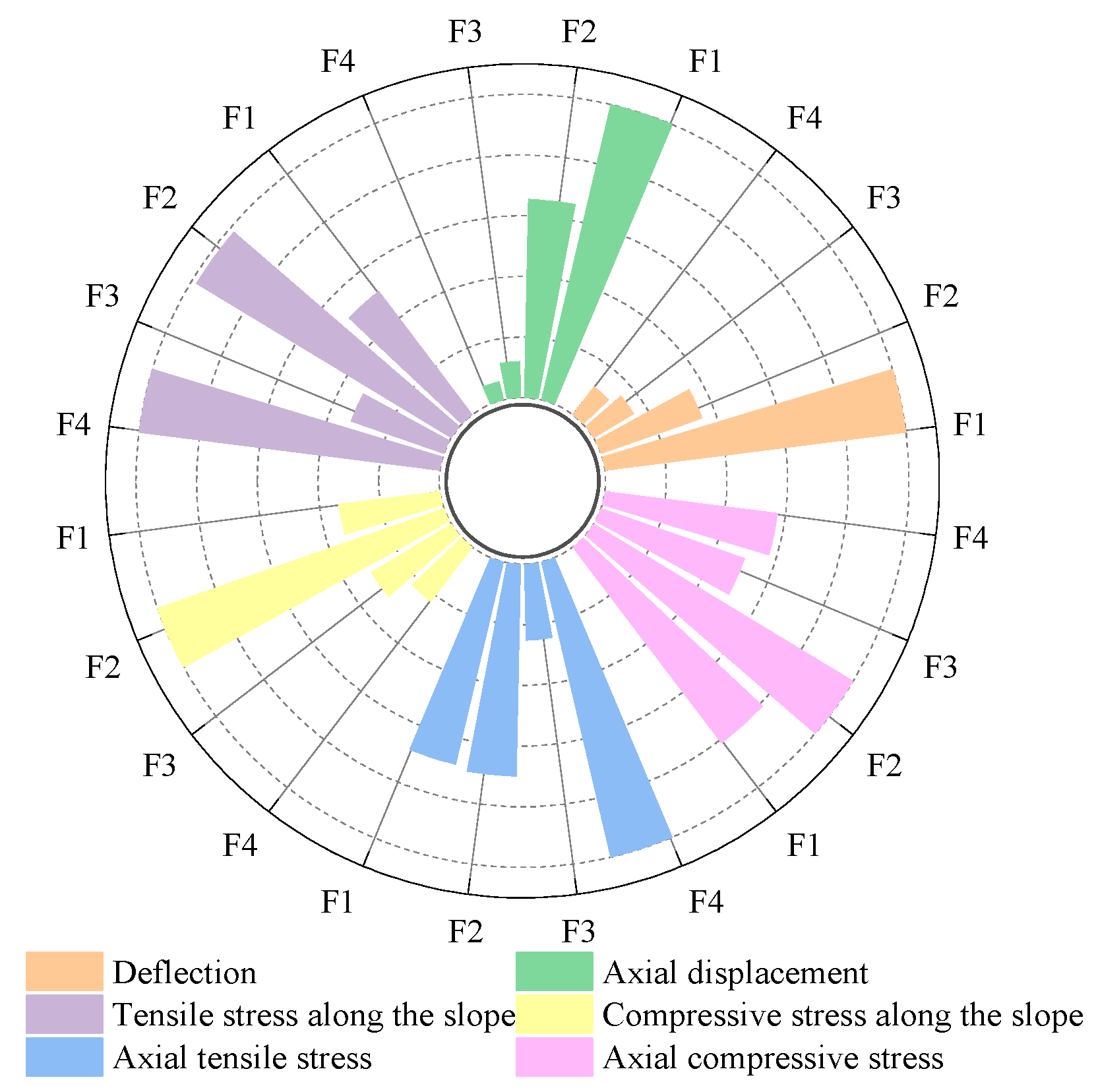
  • Similarly, the relative weights of influence on the stress and deformation characteristics of the panel were established. Using panel deflection as an example, the relative influence weights of dam height, bank slope gradient, water storage, and panel phased construction on panel deflection are 1.000, 0.352, 0.115, and 0.154, respectively. In this case, the sensitivity of influencing factors on panel deflection during the water storage period also ranges from strong to weak: dam height > bank slope gradient > panel phased construction > water storage. Similarly, as for the sensitivity of influencing factors to the tensile stress of the panel, the ranking is as follows: water storage > bank slope gradient > dam height > panel phased construction. Regarding sensitivity to axial compressive stress, the ranking is as follows: bank slope gradient > dam height > water storage > panel phased construction. Finally, sensitivity to compressive stress along the slope is ranked as follows: bank slope gradient > dam height > panel phased construction > water storage. Overall, among the four factors, dam height, bank slope gradient, and water storage have a significant impact on the stress and deformation of the panel.
  • Based on the results of aforementioned sensitivity analysis, priority design and construction factors can be identified. For instance, dam height exhibits a substantial influence on the settlement of the dam body and the deflection of the panels; accordingly, as the dam height increases, so too do the settlement of the dam body and the deflection of the panels. Consequently, to maintain optimal control over the settlement of the dam body and the deflection of the panels, it is imperative that the height of the dam body is not excessively high. This analysis can also pinpoint the factors with the most significant impact on structural performance, allowing for further risk assessment and management. Enhancing structural performance through adjusting influential factors and optimizing existing engineering design is achievable.
  • Research into the rule of stress and deformation influence on CFRDs indicated that an increase in dam height correlates with escalating stress and deformation in the dam and panel. The deformation characteristics of the panels amplify as the bank slope gradient decreases. The axial stress and compressive stress along the slope of the panel gradually decreases with the decrease in the bank slope, while the tensile stress along the slope exhibits an opposing trend; and after the slope of the bank slows down, the range of tensile stresses along the slope and axial of the panel also increases. According to the sensitivity analysis results, the effect of water storage on the stress and deformation characteristics of the dam body is not significant compared to the panel, and only the influence of water storage on the stress and deformation of the panel is discussed. Compared to a single storage event, deflection, axial horizontal displacement, stress along the slope direction, and axial tensile stress of the panel are reduced under multiple storage scenarios. Furthermore, with an increasing number of storage events, the tensile zone at the bottom of the face slab transitions into a compressive zone. It is concluded that multiple storage schemes for the face slab are more advantageous than a single storage scheme.
  • The data pertaining to seismic damage on CFRDs indicate the substantial impact of earthquakes on the stress and deformation characteristics of such CFRDs. Nevertheless, the current investigation is primarily concerned with static computations and analyses, thus neglects to examine the stress and deformation properties of CFRDs subjected to dynamic conditions. It is recommended that subsequent research incorporates dynamic assessments under seismic influence to ascertain and enhance a dam’s seismic resilience under extreme scenarios.

Author Contributions

Software, H.L. and C.F.; investigation, H.L. and Y.L.; data curation, H.L.; writing—original draft preparation, H.L.; writing—review and editing, J.W.; visualization, J.W. All authors have read and agreed to the published version of the manuscript.

Funding

This research was funded by the 2019 Tianchi Doctoral Program of the Autonomous Region, grant number 390000017, and the Xinjiang Agricultural University High-Level Talent Research and Cultivation Program Project in 2020, grant number 2521GCCRC.

Institutional Review Board Statement

Not applicable.

Informed Consent Statement

Not applicable.

Data Availability Statement

The original contributions presented in the study are included in the article.

Conflicts of Interest

The authors declare no conflicts of interest.

References

  1. Song, R.H.; Chai, J.R.; Xu, Z.G.; Qin, Y.; Cao, J. Influence of Abutment Slope Angle Variety on the Deformation and Stress of the Concrete-Faced Rockfill Dam during Initial Impoundment. Int. J. Civ. Eng. 2019, 17, 581–595. [Google Scholar] [CrossRef]
  2. Wang, R.Y.; Yu, K.P. Stress and Deformation Analysis of High Concrete Face Rockfill Dam Based on COMSOL Multiphysics. IOP Conf. Ser. Earth Environ. Sci. 2021, 643, 012013. [Google Scholar] [CrossRef]
  3. Chen, S.S.; Fu, Z.Z.; Mi, Z.K. Technical challenges and design features of the 247-m DaShixia concrete-faced sand-gravel dam. Pract. Period Struct. Des. Constr. 2022, 27, 04021073. [Google Scholar] [CrossRef]
  4. Modares, M.; Quiroz, J.E. Structural Analysis Framework for Concrete-Faced Rockfill Dams. Int. J. Geomech. 2015, 16, 04015024. [Google Scholar] [CrossRef]
  5. Zhou, W.; Hua, J.J.; Chang, X.L.; Zhou, C.B. Settlement analysis of the Shuibuya concrete-face rockfill dam. Comput. Geotech. 2011, 38, 269–280. [Google Scholar] [CrossRef]
  6. Jia, J.S.; Xu, Y.; Hao, J.T.; Zhang, L.M. Localizing and Quantifying Leakage through CFRDs. J. Geotech. Geoenviron. Eng. 2016, 142, 06016007. [Google Scholar] [CrossRef]
  7. Ma, H.Q.; Chi, F.D. Technical progress on researches for the safety of high concrete-faced rockfill dams. Engineering 2016, 2, 332–339. [Google Scholar] [CrossRef]
  8. Xu, H.; Zou, D.G.; Kong, X.J.; Hu, Z.Q. Study on the effects of hydrodynamic pressure on the dynamic stresses in slabs of high CFRD based on the scaled boundary finite-element method. Soil Dyn. Earthq. Eng. 2016, 88, 223–236. [Google Scholar] [CrossRef]
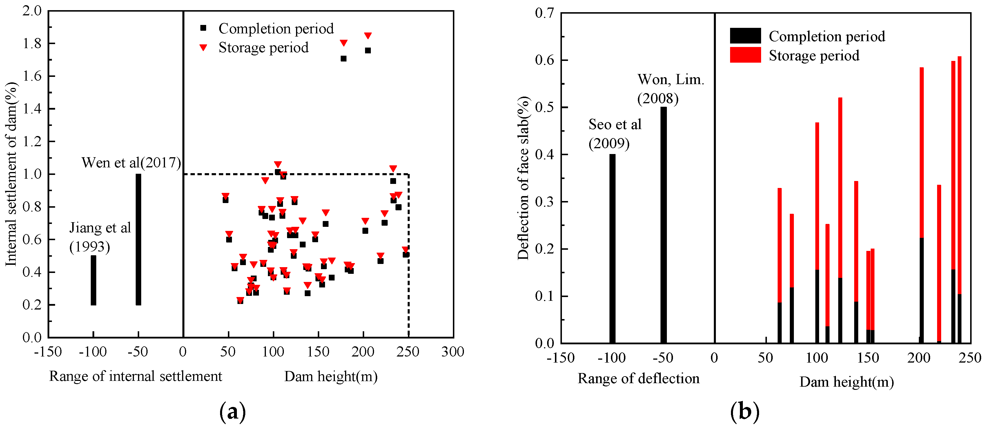
  9. Wen, L.F.; Chai, J.R.; Xu, Z.G.; Qin, Y.; Li, Y.L. Preliminary statistical analysis of behavior of concrete face rockfill dams. Chin. J. Geotech. Eng. 2017, 39, 1312–1320. (In Chinese) [Google Scholar]
  10. Jiang, G.; Cao, K. Concrete face rockfill dams in China. In Proceedings of the International Symp on High Earth–Rockfill Dams, Beijing, China, 26–29 October 1993; pp. 25–37. [Google Scholar]
  11. Seo, M.W.; Ha, I.S.; Kim, Y.S.; Oison, S.M. Behavior of concrete–faced rockfill dams during initial impoundment. J. Geotech. Geoenviron. Eng. 2009, 135, 1070–1081. [Google Scholar] [CrossRef]
  12. Won, M.S.; Kim, Y.S. A case study on the post–construction deformation of concrete face rockfill dams. Can. Geotech. J. 2008, 45, 845–852. [Google Scholar] [CrossRef]
  13. Yang, Z.H.; Yang, W.; Yang, H.H.; Liu, L.; He, J.X. Study of stress-strain relationship of hydraulic asphalt concrete at low to intermediate temperatures based on experimental data regression. Constr. Build. Mater. 2023, 409, 134059. [Google Scholar] [CrossRef]
  14. Qi, X.N.; Liu, Z.Y.; Li, D.D. Prediction of the performance of a shower cooling tower based on projection pursuit regression. Appl. Therm. Eng. 2007, 28, 1031–1038. [Google Scholar] [CrossRef]
  15. Qin, C.; Gong, J.W.; Xie, G.C. Modeling hydration kinetics of the Portland-Cement-Based cementitious systems with mortar blends by Non-Assumptive projection pursuit regression. Thermochim. Acta 2021, 705, 179035. [Google Scholar] [CrossRef]
  16. Gong, J.W.; Jiang, C.M.; Tang, X.J.; Zheng, Z.G.; Yang, L.X. Optimization of mixture proportions in ternary low-heat Portland cement-based cementitious systems with mortar blends based on projection pursuit regression. Constr. Build. Mater. 2019, 238, 117666. [Google Scholar] [CrossRef]
  17. Gong, J.W.; Zheng, R.X.; Qin, C.; Chen, R.; Cao, G. Prediction of thermal conductivity of concrete under variable temperatures in cold regions using projection pursuit regression. Cold Reg. Sci. Technol. 2022, 203, 103642. [Google Scholar] [CrossRef]
  18. Qin, C.; Gong, J.W.; Xie, G.C.; He, J.X.; Liu, L.; Yang, H.H.; Deng, C.L. Non-hypothetical projection pursuit regression for the prediction of hydration heat of Portland-cement-based cementitious system. Heliyon 2023, 9, e19471. [Google Scholar] [CrossRef] [PubMed]
  19. Gong, J.W.; Zhan, X.H.; Gong, M.M.; Wang, L.; Xie, G.C. Mechanical strength characteristics of saline soil stabilized by all-solid waste cementitious material based on projection pursuit regression modeling. J. Mater. Cycles Waste Manag. 2023, 25, 3490–3507. [Google Scholar] [CrossRef]
  20. Zhang, W.B.; Shen, Z.Z.; Ren, J.; Gan, L.; Xu, L.Q.; Sun, Y.Q. Phase-field simulation of crack propagation in quasi-brittle materials: COMSOL implementation and parameter sensitivity analysis. Model. Simul. Mater. Sci. Eng. 2021, 29, 055020. [Google Scholar] [CrossRef]
  21. Xing, H.F.; Gong, X.N.; Zhou, X.G.; Fu, H.F. Construction of concrete-faced rockfill dams with weak rocks. J. Geotech. Geoenviron. Eng. 2006, 132, 778–785. [Google Scholar] [CrossRef]
  22. Saboya, F., Jr.; Byrne, P.M. Parameters for stress and deformation analysis of rockfill dams. Can. Geotech. J. 1993, 30, 690–701. [Google Scholar] [CrossRef]
  23. Jia, Y.F.; Xu, B.; Chi, S.C.; Xiang, B.; Xiao, D.; Zhou, Y. Joint back analysis of the creep deformation and wetting deformation parameters of soil used in the Guanyinyan composite dam. Comput. Geotech. 2018, 96, 167–177. [Google Scholar] [CrossRef]
Figure 1. Statistical patterns related to the maximum internal settlement of dam body and maximum deflection of panel relative to dam height. (a) Maximum internal settlement of dam [9,10]; (b) maximum deflection of panel [11,12].
Applsci 14 08268 g001
Figure 2. Standard cross-section of a 250 m CFRD.
Applsci 14 08268 g002
Figure 3. Finite element model of a 250 m CFRD.
Applsci 14 08268 g003
Figure 4. The relative weight distribution of influencing factors on stress and deformation characteristics of the dam body.
Applsci 14 08268 g004
Figure 5. The relative weight distribution of influencing factors on stress and deformation characteristics of the panel.
Applsci 14 08268 g005
Figure 6. Changes in stress and deformation characteristics of the dam body and panel during the storage period under different dam height conditions: (a) internal settlement of the dam body; (b) deflection of the panel; (c) stress along the slope direction of the panel; (d) stress along the axial direction of the panel.
Applsci 14 08268 g006
Figure 7. Distribution of stress along the slope and axial direction in the face slab under different dam height conditions: (a) axial stress in the panel under 200 m/MPa; (b) stress along the slope in the panel under 200 m/MPa; (c) axial stress in the panel under 300 m/MPa; (d) stress along the slope in the panel under 300 m/MPa.
Applsci 14 08268 g007
Figure 8. Changes in deformation and stress characteristics of the dam body and panel under different bank slope gradient conditions during the water storage period: (a) deformation; (b) stress.
Applsci 14 08268 g008
Figure 9. Distribution of stress along the slope and axial direction in the panel under different bank slope gradient conditions: (a) axial stress at a bank slope gradient of 1:0.5/MPa; (b) stress along the slope at a bank slope gradient of 1:0.5/MPa; (c) axial stress at a bank slope gradient of 1:1.5/MPa; (d) stress along the slope at a bank slope gradient of 1:1.5/MPa.
Applsci 14 08268 g009
Figure 10. Changes in stress and deformation characteristics of the panel during completion and storage periods under different water storage conditions: (a) deflection; (b) stress along the slope; (c) stress along the axial.
Applsci 14 08268 g010
Figure 11. Stress contour maps along the slope and axial of the panel under the one-time and three-times water storage schemes: (a) stress contour map along an axial direction/MPa; (b) stress contour map along a slope direction/MPa.
Applsci 14 08268 g011
Table 1. Statistical information and performance data from partial concrete-faced rockfill dams.
No.DamHeight/mBank Slope Gradient/°Maximum Settlement of Dam/cmMaximum Deflection of Panel/cm
Completion PeriodStorage PeriodCompletion PeriodStorage Period
1Gongboxia139.00 The valley is asymmetric, with 30 on the left bank and 40~50 on the right bank58.60 60.60 9.60 22.10
2Yutiao110.00 Asymmetric V-shaped valley, left bank 35~50, right bank 55~7082.00 85.00 2.90 16.90
3Zipingpu156.00 Asymmetric V-shaped valley, left bank 40~50, right bank 20~2568.10 73.40 40.00
4Xianyou75.10 V-shaped valley, 40~6024.00 26.80 6.40 8.30
5Jiangpinghe219.00 102.40 110.80 0.90 51.50
6Jiudianxia136.50 About 85 below the elevation of 2145 m on the left bank, 30 to 40 above, and 30 to 45 on the right bank58.80 60.10 1.60 3.40
7Uruwati138.00 U-shaped37.40 44.90 8.80 25.00
8Shuibuya233.00 Asymmetric V-shaped valley, with an average of 52 on the left bank and 35 on the right bank223.00 242.00 26.20 73.30
9Shanxi132.50 U-shaped valley, left bank 30~40, right bank 40~4575.40 95.30 20.00
10Jiayan154.00 Asymmetric V-shaped49.80 55.40 3.21 18.80
11Tianshengqiao178.00 V-shaped valley, left bank 20~30, right bank 18~30304.00 322.00 81.00
12Jiayan154.00 Asymmetric V-shaped49.80 55.40 3.21 18.80
13Hekoucun122.50 U-shaped61.40 64.50 12.24 33.28
14Dashixia247.00 Asymmetric V-shaped, 45~75125.30 134.00 4.60 47.20
15Cihaxia202.00 V-shaped valley, 42~45145.00 32.42 51.84
16Hongjiadu182.30 Asymmetric V-shaped valley, with a steep left bank of 70 and a right bank of 25~4075.90 82.05 46.00
17Taoshui102.00 Left bank 46~49, right bank 27~2960.60 64.30 5.57 24.47
18Dongjin150.00Slightly wide and asymmetrical V-shaped valley, left bank 35, right bank 25–28194.5059.70
Table 2. Calculation scheme.
No.Dam Height/mBank Slope GradientPanel Phased ConstructionWater Storage
12001:0.5011
22001:1.0032
32001:1.5023
42501:0.5033
52501:1.0021
62501:1.5012
73001:0.5022
83001:1.0013
93001:1.5031
Table 3. Duncan Chang E-B model parameters of the rock-filling materials.
MaterialsRfKn φ KbmKur ρ d /(g·cm−3)
Cushion material0.828500.4549.903500.0817002.29
Transition material0.708700.5255.305800.2017402.23
Rockfill material0.7512500.3052.209200.1125002.20
Table 4. Relative weight contribution values of influencing factors on characteristics of the dam body.
Extreme Values of Deformation CharacteristicsInfluence FactorRelative Weight Contribution Value
Completion PeriodStorage Period
Internal settlementF11.0001.000
F20.4040.439
F30.0140.014
F40.0170.025
Displacement along the riverF11.0001.000
F20.6440.756
F30.1260.045
F40.1290.086
Axial displacementF11.0001.000
F20.4720.440
F30.1980.160
F40.2010.239
Table 5. Relative weight contribution values of influencing factors on characteristics of the panel.
Extreme Values of Stress Deformation CharacteristicsInfluence FactorRelative Weight Contribution Value
Completion PeriodStorage Period
DeflectionF11.0001.000
F20.3160.352
F30.1830.154
F40.1020.115
Axial displacementF10.2771.000
F21.0000.654
F30.2830.120
F40.2080.062
Tensile stress along the slope directionF10.6950.510
F21.0000.982
F30.9190.324
F40.5161.000
Compressive stress along the slope directionF10.4410.336
F21.0001.000
F30.8380.309
F40.3740.225
Axial tensile stressF11.0000.686
F20.3800.700
F30.3030.251
F40.6361.000
Axial compressive stressF10.3440.811
F21.0001.000
F30.6010.502
F40.2710.574
Table 6. Calculation scheme.
No.Calculation SchemeDam Height/mBank Slope GradientWater Storage
11-12001:1.02
1-2250
1-3300
22-12501:0.52
2-21:1.0
2-31:1.5
33-12501:0.51
3-22
3-33
Table 7. Characteristic stress and deformation values of the dam and panel during the water storage period.
SchemeDam BodyPanel
Internal Settlement/cmAlong the River Displacement/cmDeflection/cmAxial Displacement/cmAlong the Slope DirectionAlong the Axial Direction
Compressive Stress/MPaTensile Stress/MPaCompressive Stress/MPaTensile Stress/MPa
1-194.4725.1138.272.665.461.6610.561.25
1-2139.5036.5857.984.267.092.6314.742.52
1-3191.8049.8380.896.469.264.7819.673.02
2-1113.4626.5951.322.936.891.0517.242.63
2-2139.5036.5857.984.267.092.6314.742.52
2-3152.3042.7264.414.866.803.0413.432.45
3-1113.2026.9753.363.017.661.2917.133.19
3-2113.4626.5951.322.936.891.0517.242.63
3-3113.5326.5251.312.906.540.8617.832.52
Disclaimer/Publisher’s Note: The statements, opinions and data contained in all publications are solely those of the individual author(s) and contributor(s) and not of MDPI and/or the editor(s). MDPI and/or the editor(s) disclaim responsibility for any injury to people or property resulting from any ideas, methods, instructions or products referred to in the content.

