
A Novel Tracking Strategy Based on Real-Time Monitoring to Increase the Lifetime of Dual-Axis Solar Tracking Systems


Abstract
1. Introduction
- A novel tracking strategy based on real-time monitoring to increase the lifetime of dual-axis solar tracking systems without reducing the energy productivity of PV systems due to the considerable reduction of operating time, and consequently, the reduction of maintenance requirements, less wear and fatigue in the tracking system, and increasing the profit and reliability during long periods.
- An approach to estimating the tracking system lifetime based on wear and tear and possible failures in the axes due to usage time of the tracking action.
- The energy consumption of tracking systems is reduced due to the decision-making algorithm considering the tracking accuracy and the gain of energy production in an integrated manner.
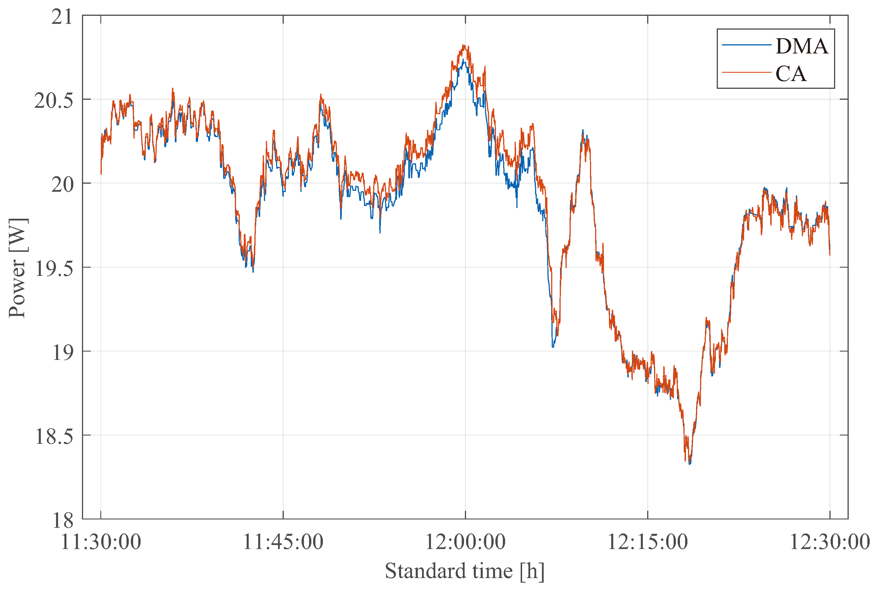
- An experimental analysis of two tracking strategies was performed by comparing the tracking errors, energy generation, and consumption of two solar tracking systems subject to the same climatic conditions.
2. Methodology
- Improving the productivity of the tracking system, transforming the biggest amount of solar energy with the least amount of energy loss due to the tracking action.
- Increasing the service life of the tracker through maximizing reliability, reducing maintenance, and prolonging the useful life of the robotic system.
2.1. Productivity of Tracking Systems
2.2. Service Life in Tracking Systems
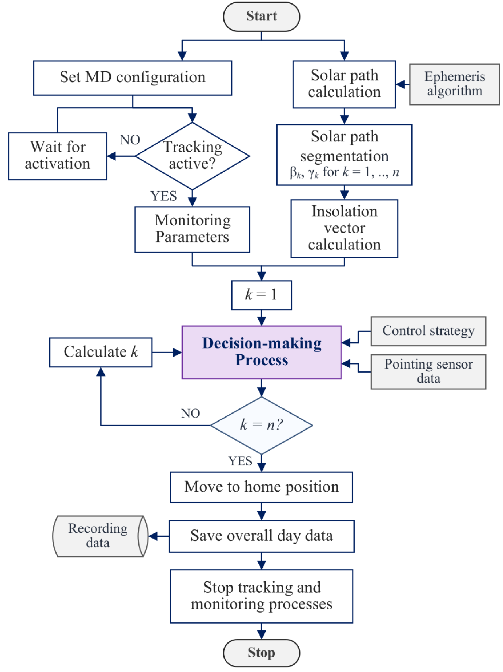
2.3. Proposed Tracking Strategy
| Algorithm 1 Decision-making process for solar tracking based on real-time measurement. |
|
3. Case Study
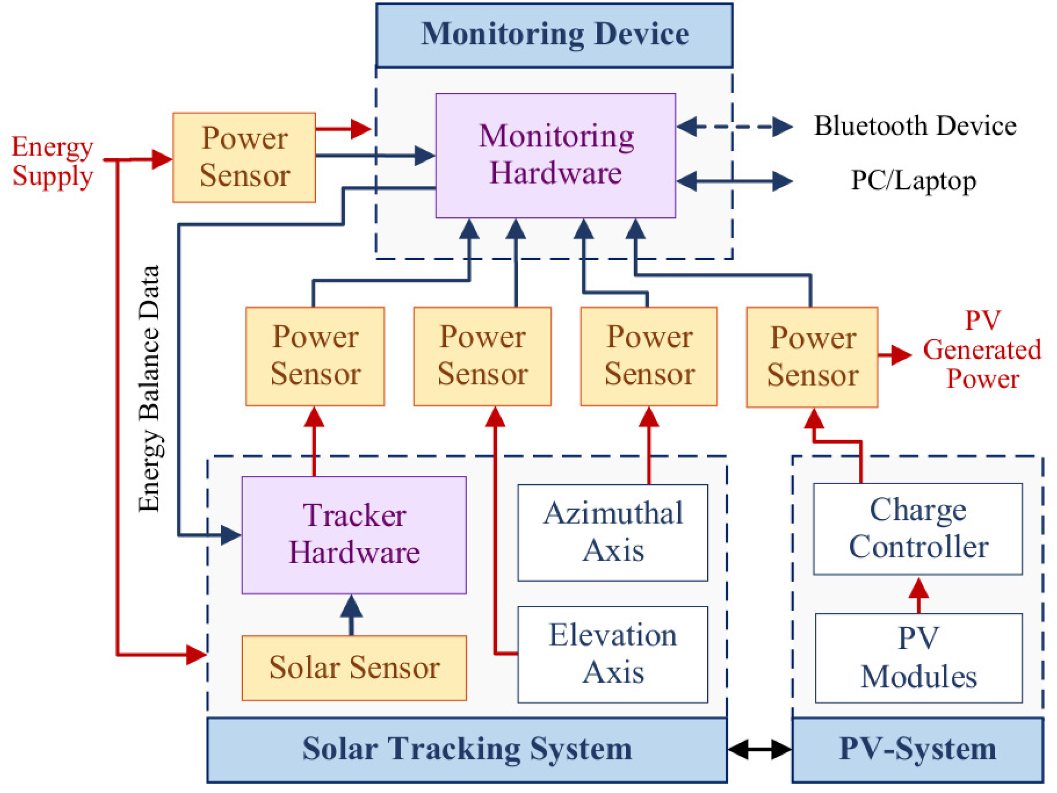
- Solar tracking system: The STS is a two-axis robot in azimuth-elevation configuration with an open architecture to freely configure the required tracking, energy saving, and control strategies. The azimuth axis has a parallel axis transmission with a 76:20 ratio gear, and the elevation axis has a worm gear mechanism with a 28:1 ratio gear, which allows the self-locking action to maintain the position without requiring energizing the actuator. Both axes have a DC gear motor with a planetary gearbox with a 188:1 ratio gear, a stall current of A at a stall torque of Nm, and a no-load speed of 30 RPM. Table 1 shows the rated output speed and torque of each axis. The angular position measurement is performed with an encoder integrated into the DC motor with a resolution of 5281 pulses per rotation at the output shaft. The system has an embedded Nucleo-F446RE board with 32-bit microcontroller and a VNH2SP30 driver for programming strategies (STMicroelectronics, Geneva, Switzerland). In addition, the tracker is equipped with a Solar Mems ISS-T60 solar pointing sensor, with a 120° field of view, two measurement angles, a precision of , and measurement of direct irradiance and ambient temperature.
- Monitoring device: An embedded system for energy monitoring in solar applications designed to be scalable, modular, and built with an open architecture was used for the tests. The device has a low energy consumption of just Wh. It features a 32-bit microcontroller with 12-bit ADCs and an integrated Real-Time Clock (RTC) for real-time data logging through four channels. With compact dimensions of 104.5 × 74 × 36 mm, the device includes a 3.5-inch touchscreen for setting up parameters, configuring data logging operations, and visualizing measured values in display, graph, or table modes. It also supports wireless data streaming via Bluetooth and Wi-Fi and wire communication through USB or UART connections to external devices.
- Photovoltaic system: The integrated system includes a PV technology module as an energy generation component with the following characteristics: an arrangement of 36 polycrystalline cells, a total dimension of 550 mm × 360 mm, a mass of kg, maximum power in STC of 25 W, and an average conversion efficiency of . In addition, it has a charge controller model PY-HP2410 (Prostar Solar, Jiangsu, China) with a maximum input solar power capacity of 170–340 W and a Solar Cale CL-31T/S-190M lead-acid battery (Enertec Mexico, Monterrey, Mexico) with a voltage of 12 V and capacity of 122 Ah. Additionally, the system can connect the output power to a charge inverter or a DC load to use the generated power.
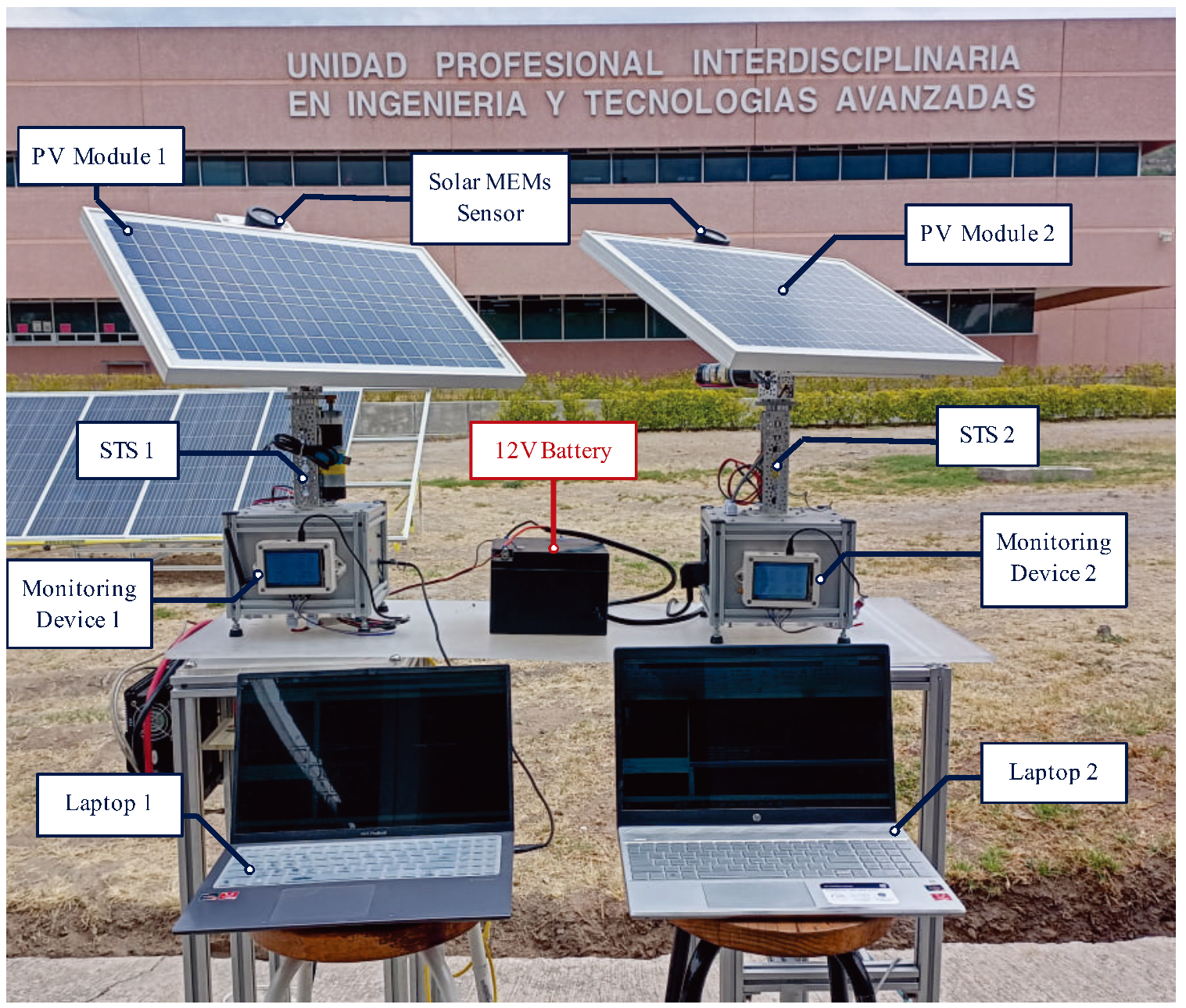
3.1. Experimental Setup
- The location for the tests was in the Applied Dynamic Systems Laboratory of the UPIITA-IPN, in Mexico City, Mexico, with a latitude and longitude of and , respectively. The day was 17 May 2024, when sunrise was at 05:59:00, noon at 12:32:00, and sunset at 19:06:00. The experimental tests began at 11:30:00 (UTC-6) and ended at 12:30:00 (UTC-6).
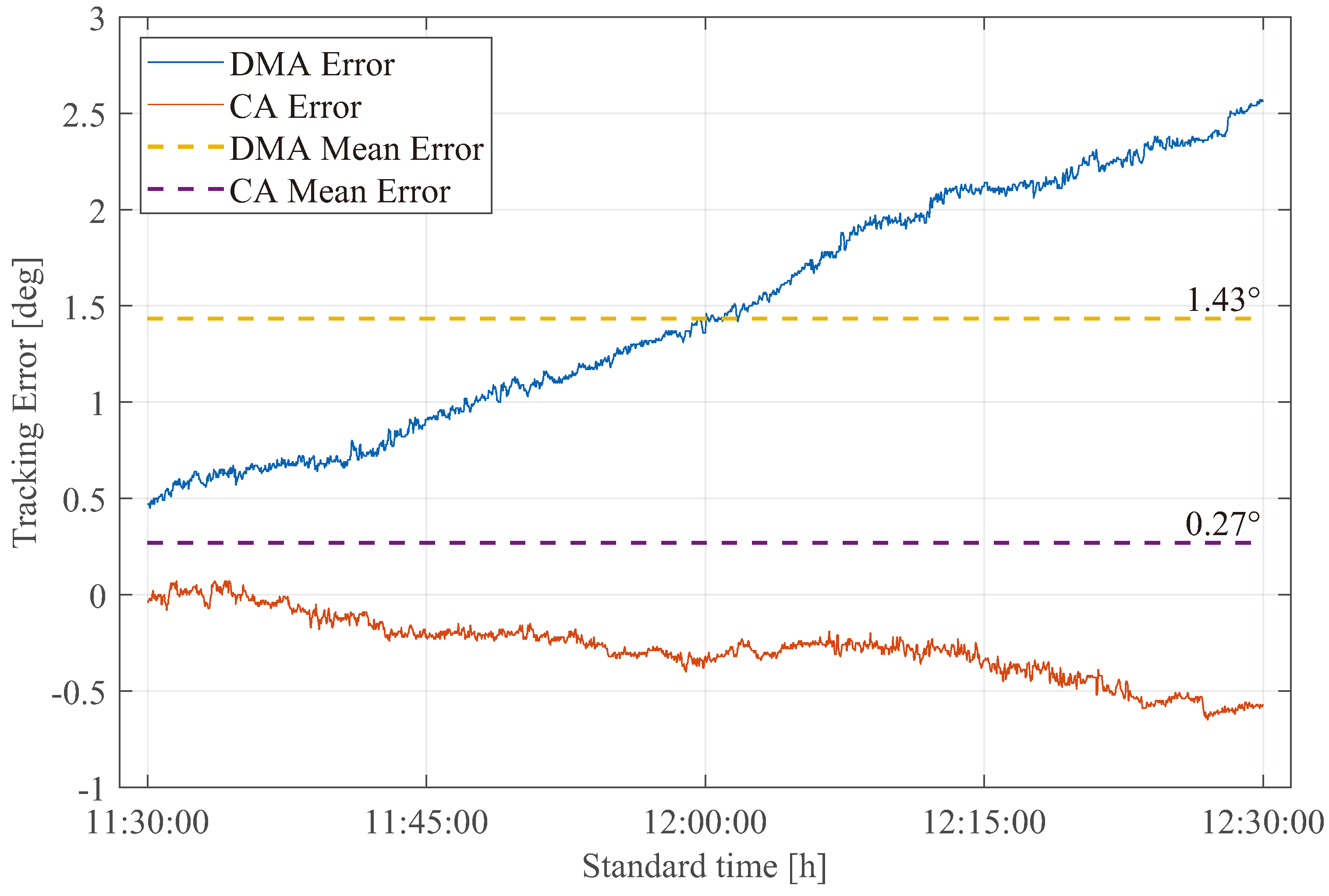
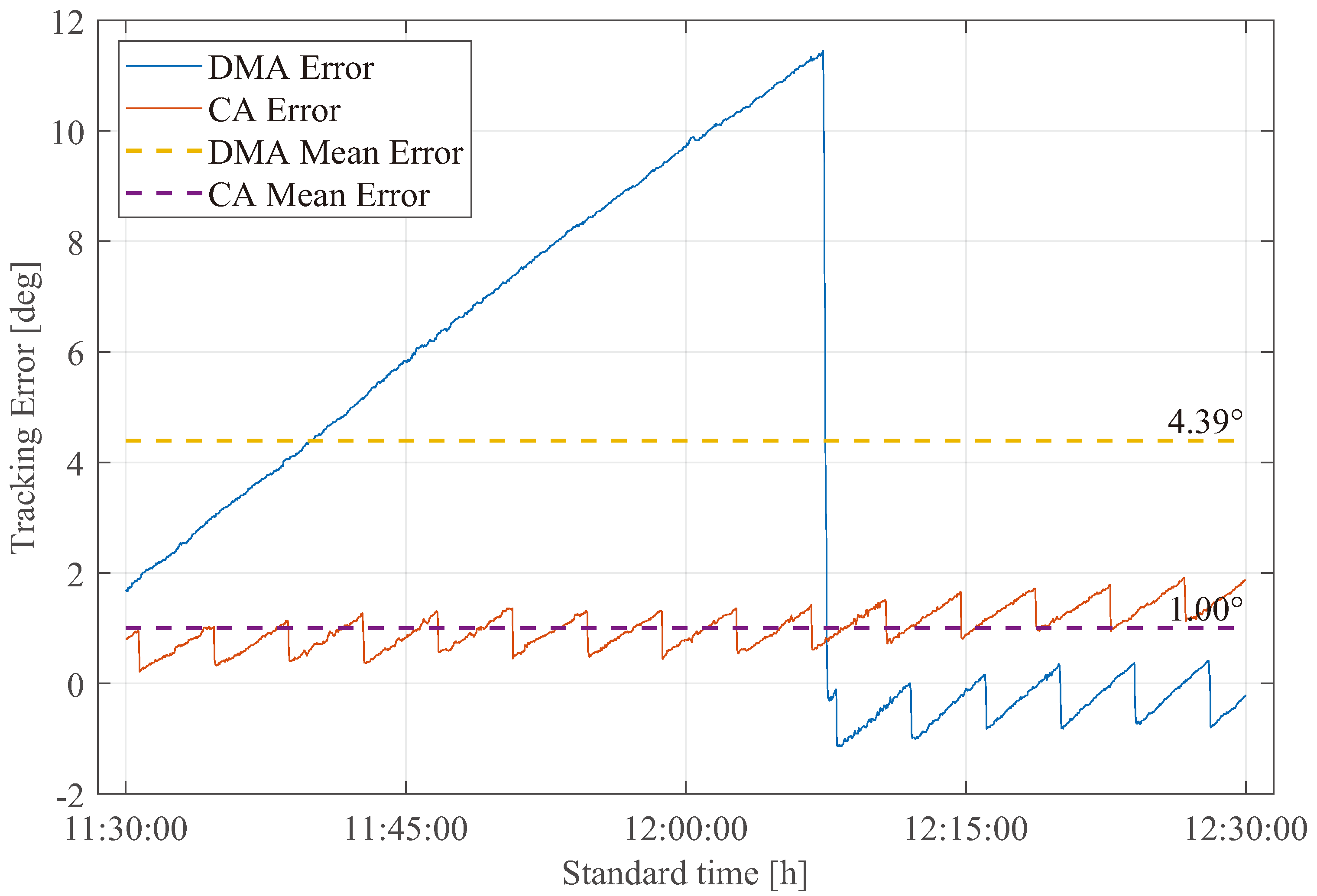
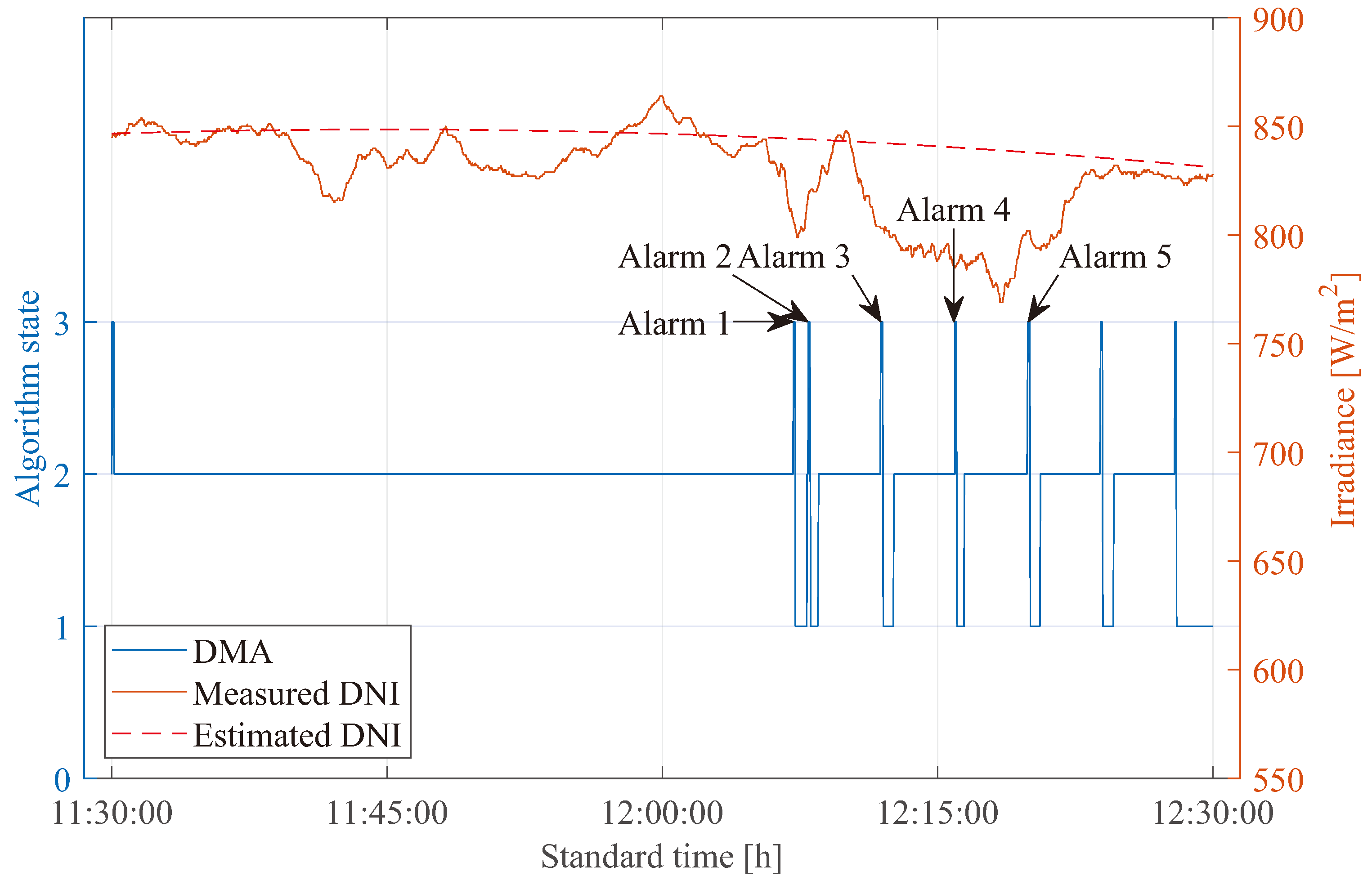
- The experimentation was in mixed weather conditions with clear and partially cloudy conditions, where the periods of cloudiness were from 11:40:00 to 12:00:00 and from 12:05:00 to 12:22:00.
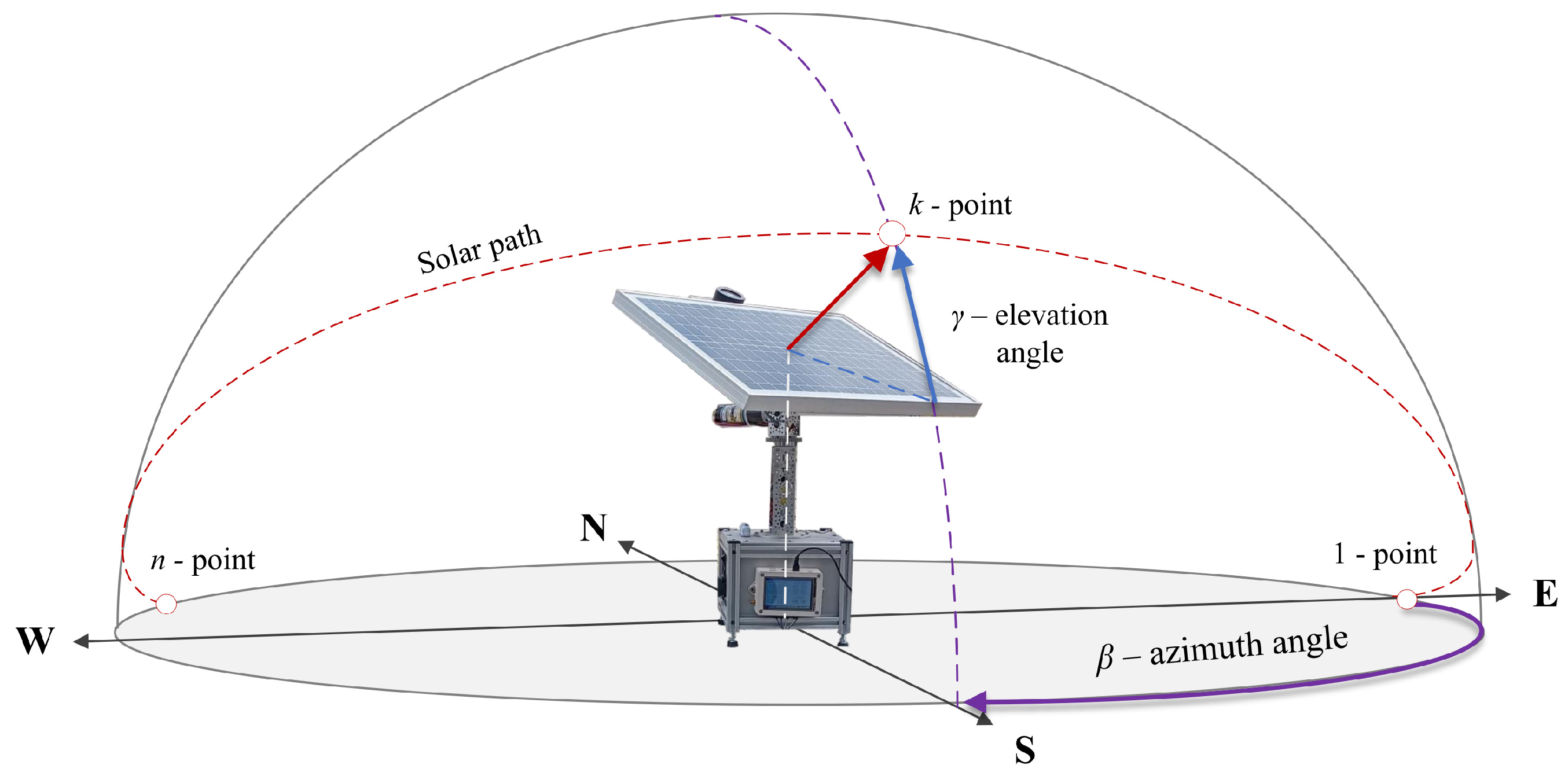
- The solar path was calculated using the Solar Position Algorithm (SPA) and segmented in intervals of 4 min, resulting in 151 steps for both axes.
- The power sensors calibration was using a Fluke 289 True RMS multimeter (Fluke Corporation, Everett, WA, USA), with a maximum error of . The calibration procedure consisted of a zero adjustment to ensure the sensor reads zero when no current is flowing and a test with a constant electric load to compare the measured value with the multimeter value.
- The acceleration and velocity profiles at the robot joints are the same for both algorithms; for this reason, they were not considered in the lifetime analysis.
- The measurements of the monitoring device channels were configured to acquire 32 samples for each reading, considering an offset and measurement error correction factor.
- Each monitoring device connects to a computer with a USB cable and wirelessly using the Bluetooth module for real-time data transmission and recording. In addition, when the monitoring process starts, a file with *.csv extension is created to continuously record the data on a Micro SD memory card configured with the exFAT file system.
- Based on the results presented in [39], the selected control strategy for both systems is the PID controller due to a balanced relationship between the mixed tracking error and energy consumption, which ensures adequate performance for the case study. For more detail, in [39], a PID controller implementation in a two-axis solar tracker is presented.
- According to the experimental tests in [29], the proposed energy-saving strategy includes the activation of the sleep mode of the tracker control hardware during idle times and the parallel activation of the axes until the desired position is reached.
3.2. Experimental Results
- For the calculation, the payload was evaluated as a constant value, only the load of the PV module; however, an increase in the applied load due to the wind force on the solar collection surface exists, affecting the study, and hence, it must be considered in future calculations.
- The analysis is carried out for the elevation axis because it is the critical element due to the configuration of the tracking robot, and the loads applied to the azimuthal axis are neglected since they are axial with a minimum impact on the bearing.
- The angular velocity is considered identical for each strategy, with an average value of RPM, which allows the service life calculation to focus on the impact on the operating time.
- The output torque for each step is calculated through the dynamic analysis of the system for each step in the trajectory, where the dynamic model is described by:where q, , and are the angular position, the velocity and acceleration of the azimuthal and elevation axis, respectively. The matrix represents the effective inertia matrix for the axis motors, is the Coriolis matrix, is the gravitational vector, and is the torque of each axis. The explicit model is defined as follows:where are the tensor of inertia, is the PV module and link structure mass, is the distance of the elevation link, g is the gravity constant, and and stand for and , respectively. For more detail, the dynamic model using the Euler–Lagrange procedure is presented in [40]. Since the load on the azimuth axis is absorbed by the bearing, the dynamic model is simplified and focused on the elevation axis, where the torque is expressed as follows:where is equal to kg, is m, and is the angular position of the elevation axis with the horizon as reference for each step in the strategies path.
- The rated service life K of the system was defined as h according to supplier recommendations for industrial robotic systems presented in [41].
4. Conclusions and Future Work
Author Contributions
Funding
Data Availability Statement
Acknowledgments
Conflicts of Interest
Abbreviations
| CA | Conventional Algorithm |
| DMA | Decision-Making Algorithm |
| MD | Monitoring device |
| PV | Photovoltaic |
| SPA | Solar Position Algorithm |
| SRF | Solar Reliability Factor |
| STS | Solar Tracking System |
| SVM | Support Vector Machine |
| PID | Proportional-Integral-Derivative |
| ROI | Return-on-investment |
| RTC | Real-Time Clock |
References
- Arshian, S.; Muhammad, S.M.; Mohammad, A.; Chowdhury, F.; Sohag, K. Role of solar energy in reducing ecological footprints: An empirical analysis. J. Clean. Prod. 2021, 292, 126028. [Google Scholar]
- Rida, F.; Shehzad, R.A.; Rasool, A.; Yaseen, M.; Iqbal, S.; Saif, M.J.; Iqbal, J. Exploring the potential of tetraazaacene derivatives as photovoltaic materials with enhanced photovoltaic parameters. Int. J. Quantum Chem. 2022, 122, e26817. [Google Scholar]
- Ramya, D.; Krishnakumari, A.; Dineshkumar, P.T.; Srivastava, M.P.; Vadivel, L.; Puthilibai, K.G.; Kumar, P.M. Investigating the influence of nanoparticle disbanded phase changing material (ndpcm) on the working of solar pv. Mater. Today Proc. 2022, 56, 1341–1346. [Google Scholar] [CrossRef]
- Shakibi, H.; Afzal, S.; Shokri, A.; Sobhani, B. Utilization of a phase change material with metal foam for the performance improvement of the photovoltaic cells. J. Energy Storage 2022, 51, 104466. [Google Scholar] [CrossRef]
- Wang, Z.; Zhang, H.; Dou, B.; Zhang, G.; Wu, W. Theoretical and experimental evaluation on the electrical properties of multi-junction solar cells in a reflective concentration photovoltaic system. Energy Rep. 2022, 8, 820–831. [Google Scholar] [CrossRef]
- Paulauskas, T.; Pačebutas, V.; Geižutis, A.; Kamarauskas, M.; Drazdys, M.; Rudzikas, M.; Kondrotas, R.; Naujokaitis, A.; Nevinskas, I.; Šebeka, B.; et al. Performance analysis of gaasbi/ingaas heterostructure for iii–v multi-junction solar cells. Sol. Energy Mater. Sol. Cells 2022, 248, 112013. [Google Scholar] [CrossRef]
- Jost, N.; Gu, T.; Hu, J.; Domínguez, C.; Antón, I. Integrated micro-scale concentrating photovoltaics: A scalable path toward high-efficiency, low-cost solar power. Sol. RRL 2023, 7, 2300363. [Google Scholar] [CrossRef]
- Fam, D.F.; Koh, S.; Kiong, T.S.; Chong, K.H. Optimization variation for multiple heuristic approaches in solar tracking. Key Eng. Mater. 2011, 480, 1085–1090. [Google Scholar] [CrossRef]
- Verma, P.; Alam, A.; Sarwar, A.; Tariq, M.; Vahedi, H.; Gupta, D.; Ahmad, S.; Mohamed, A.S.N. Meta-heuristic optimization techniques used for maximum power point tracking in solar pv system. Electronics 2021, 10, 2419. [Google Scholar] [CrossRef]
- Flores-Hernández, D.A.; Luviano-Juárez, A.; Lozada-Castillo, N.; Gutiérrez-Frías, O.; Domínguez, C.; Antón, I. Optimal strategy for the improvement of the overall performance of dual-axis solar tracking systems. Energies 2021, 14, 7795. [Google Scholar] [CrossRef]
- Kuttybay, N.; Mekhilef, S.; Koshkarbay, N.; Saymbetov, A.; Nurgaliyev, M.; Dosymbetova, G.; Orynbassar, S.; Yershov, E.; Kapparova, A.; Zholamanov, B.; et al. Assessment of solar tracking systems: A comprehensive review. Sustain. Energy Technol. Assessments 2024, 68, 103879. [Google Scholar] [CrossRef]
- Hafez, A.Z.; Yousef, A.M.; Harag, N.M. Solar tracking systems: Technologies and trackers drive types—A review. Renew. Sustain. Energy Rev. 2018, 91, 754–782. [Google Scholar] [CrossRef]
- Adouni, A.; Elmellah, K.; Chariag, D.; Sbita, L. Dc-dc converter fault diagnostic in pv system. In Proceedings of the 2017 International Conference on Green Energy Conversion Systems (GECS), Hammamet, Tunisia, 23–25 March 2017; IEEE: Piscataway, NJ, USA, 2017; pp. 1–7. [Google Scholar]
- Jain, P.; Xu, J.-X.; Panda, S.K.; Poon, J.; Spanos, C.; Sanders, S.R. Fault diagnosis via pv panel-integrated power electronics. In Proceedings of the 2016 IEEE 17th Workshop on Control and Modeling for Power Electronics (COMPEL), Trondheim, Norway, 27–30 June 2016; IEEE: Piscataway, NJ, USA, 2016; pp. 1–6. [Google Scholar]
- Natarajan, K.; Bala, P.K.; Sampath, V. Fault detection of solar pv system using svm and thermal image processing. Int. Renew. Energy Res. 2020, 10, 967–977. [Google Scholar]
- Alwar, S.; Samithas, D.; Boominathan, M.S.; Balachandran, P.K.; Mihet-Popa, L. Performance analysis of thermal image processing-based photovoltaic fault detection and pv array reconfiguration—A detailed experimentation. Energies 2022, 15, 8450. [Google Scholar] [CrossRef]
- El-Banby, G.M.; Moawad, N.M.; Abouzalm, B.A.; Abouzaid, W.F.; Ramadan, E.A. Photovoltaic system fault detection techniques: A review. Neural Comput. Appl. 2023, 35, 24829–24842. [Google Scholar] [CrossRef]
- Jurj, S.L.; Rotar, R.; Opritoiu, F.; Vladutiu, M. Improving the solar reliability factor of a dual-axis solar tracking system using energy-efficient testing solutions. Energies 2021, 14, 2009. [Google Scholar] [CrossRef]
- Jurj, S.L.; Rotar, R. Increasing the solar reliability factor of a dual-axis solar tracker using an improved online built-in self-test architecture. IEEE Access 2024, 12, 37715–37730. [Google Scholar] [CrossRef]
- Jurj, S.L.; Rotar, R.; Opritoiu, F.; Vladutiu, M. Hybrid testing of a solar tracking equipment using in-circuit testing and jtag debugging strategies. In Proceedings of the 2021 IEEE International Conference on Environment and Electrical Engineering and 2021 IEEE Industrial and Commercial Power Systems Europe (EEEIC/I and CPS Europe), Bari, Italy, 7–10 September 2021; IEEE: Piscataway, NJ, USA, 2021; pp. 1–10. [Google Scholar]
- Jurj, S.L.; Rotar, R.; Opritoiu, F.; Vladutiu, M. White-box testing strategy for a solar tracking device using nodeMCU lua ESP8266 wi-fi network development board module. In Proceedings of the 2018 IEEE 24th International Symposium for Design and Technology in Electronic Packaging (SIITME), Iasi, Romania, 25–28 October 2018; IEEE: Piscataway, NJ, USA, 2018; pp. 53–60. [Google Scholar]
- Valentín, D.; Valero, C.; Egusquiza, M.; Presas, A. Failure investigation of a solar tracker due to wind-induced torsional galloping. Eng. Fail. Anal. 2022, 135, 106137. [Google Scholar] [CrossRef]
- Rathika, N.; Raman, R.; Sutaria, K.K.; Dattatreya, S.; Reddy, R.S.; Muthulekshmi, M. Intelligent solar tracking system with fuzzy logic control and iot integration. In Proceedings of the 2024 2nd International Conference on Computer, Communication and Control (IC4), Indore, India, 8–10 February 2024; IEEE: Piscataway, NJ, USA, 2024; pp. 1–5. [Google Scholar]
- Singh, A.K.; Chauhan, Y.; Sharma, N. Comparative performance analysis of intelligent controllers for solar tracking system. Mater. Today Proc. 2022, 65, 3731–3740. [Google Scholar] [CrossRef]
- Kanwal, T.; Rehman, S.U.; Ali, T.; Mahmood, K.; Villar, S.G.; Lopez, L.A.D.; Ashraf, I. An intelligent dual-axis solar tracking system for remote weather monitoring in the agricultural field. Agriculture 2023, 13, 1600. [Google Scholar] [CrossRef]
- Holden, E.; Linnerud, K.; Rygg, B.J. A review of dominant sustainable energy narratives. Renew. Sustain. Energy Rev. 2021, 144, 110955. [Google Scholar] [CrossRef]
- Saldivar-Aguilera, T.Q.; Valentín-Coronado, L.M.; Peña-Cruz, M.I.; Diaz-Ponce, A.; Dena-Aguilar, J.A. Novel closed-loop dual control algorithm for solar trackers of parabolic trough collector systems. Sol. Energy 2023, 259, 381–390. [Google Scholar] [CrossRef]
- Lo, S.; Cheng, F.; Chang, V.; Liu, W.D.J.; Chang, L.; Adurodija, O.F.; Chou, E.; Lung, C.; Liu, J.; Lu, T.; et al. Design, operation, and performance evaluation of a cable-drawn dual-axis solar tracker compared to a fixed-tilted system. Energy Sci. Eng. 2015, 3, 549–557. [Google Scholar] [CrossRef]
- Flores-Hernández, D.A.; Palomino-Resendiz, S.I.; Luviano-Juárez, A.; Lozada-Castillo, N.; Gutierrez-Frias, O. A heuristic approach for tracking error and energy consumption minimization in solar tracking systems. IEEE Access 2019, 7, 52755–52768. [Google Scholar] [CrossRef]
- Fuentes-Morales, R.F.; Diaz-Ponce, A.; Peña-Cruz, M.I.; Rodrigo, P.M.; Valentín-Coronado, L.M.; Martell-Chavez, F.; Pineda-Arellano, C.A. Control algorithms applied to active solar tracking systems: A review. Sol. Energy 2020, 212, 203–219. [Google Scholar] [CrossRef]
- Mousazadeh, H.; Keyhani, A.; Javadi, A.; Mobli, H.; Abrinia, K.; Sharifi, A. A review of principle and sun-tracking methods for maximizing solar systems output. Renew. Sustain. Energy Rev. 2009, 13, 1800–1818. [Google Scholar] [CrossRef]
- Mousazadeh, H.; Keyhani, A.; Javadi, A.; Mobli, H.; Abrinia, K.; Sharifi, A. Path-constrained trajectory planning for robot service life optimization. In Proceedings of the 2016 American Control Conference (ACC), Boston, MA, USA, 6–8 July 2016; IEEE: Piscataway, NJ, USA, 2016; pp. 2116–2122. [Google Scholar]
- Reda, I.; Andreas, A. Solar position algorithm for solar radiation applications. Sol. Energy 2004, 76, 577–589. [Google Scholar] [CrossRef]
- Blanco-Muriel, M.; Alarcón-Padilla, D.C.; López-Moratalla, T.; Lara-Coira, M. Computing the solar vector. Sol. Energy 2001, 70, 431–441. [Google Scholar] [CrossRef]
- Grena, R. An algorithm for the computation of the solar position. Sol. Energy 2008, 82, 462–470. [Google Scholar] [CrossRef]
- Cooper, P.I. The absorption of radiation in solar stills. Sol. Energy 1969, 12, 333–346. [Google Scholar] [CrossRef]
- Jiang, J.A.; Wang, J.C.; Kuo, K.C.; Su, Y.L.; Shieh, J.C. On evaluating the effects of the incident angle on the energy harvesting performance and mpp estimation of pv modules. Int. J. Energy Res. 2014, 38, 1304–1317. [Google Scholar] [CrossRef]
- Masters, G.M. Renewable and Efficient Electric Power Systems; John Wiley & Sons: Hoboken, NJ, USA, 2013. [Google Scholar]
- Palomino-Resendiz, S.I.; Ortiz-Martínez, F.A.; Paramo-Ortega, I.V.; González-Lira, J.M.; Flores-Hernández, D.A. Optimal selection of the control strategy for dual-axis solar tracking systems. IEEE Access 2023, 11, 56561–56573. [Google Scholar] [CrossRef]
- Palomino-Resendiz, S.I.; Lozada-Castillo, N.B.; Flores-Hernández, D.A.; Gutiérrez-Frías, O.O.; Luviano-Juárez, A. Adaptive active disturbance rejection control of solar tracking systems with partially known model. Mathematics 2021, 9, 2871. [Google Scholar] [CrossRef]
- Abd Majid, M.A.; Fudzin, F. Study on robots failures in automotive painting line. Asian Res. Publ. Netw. 2017, 12, 62–67. [Google Scholar]


| Axis | [RPM] | [Nm] |
|---|---|---|
| Azimuth | ||
| Elevation |
| Algorithm | [°] | [°] | [°] | |||
|---|---|---|---|---|---|---|
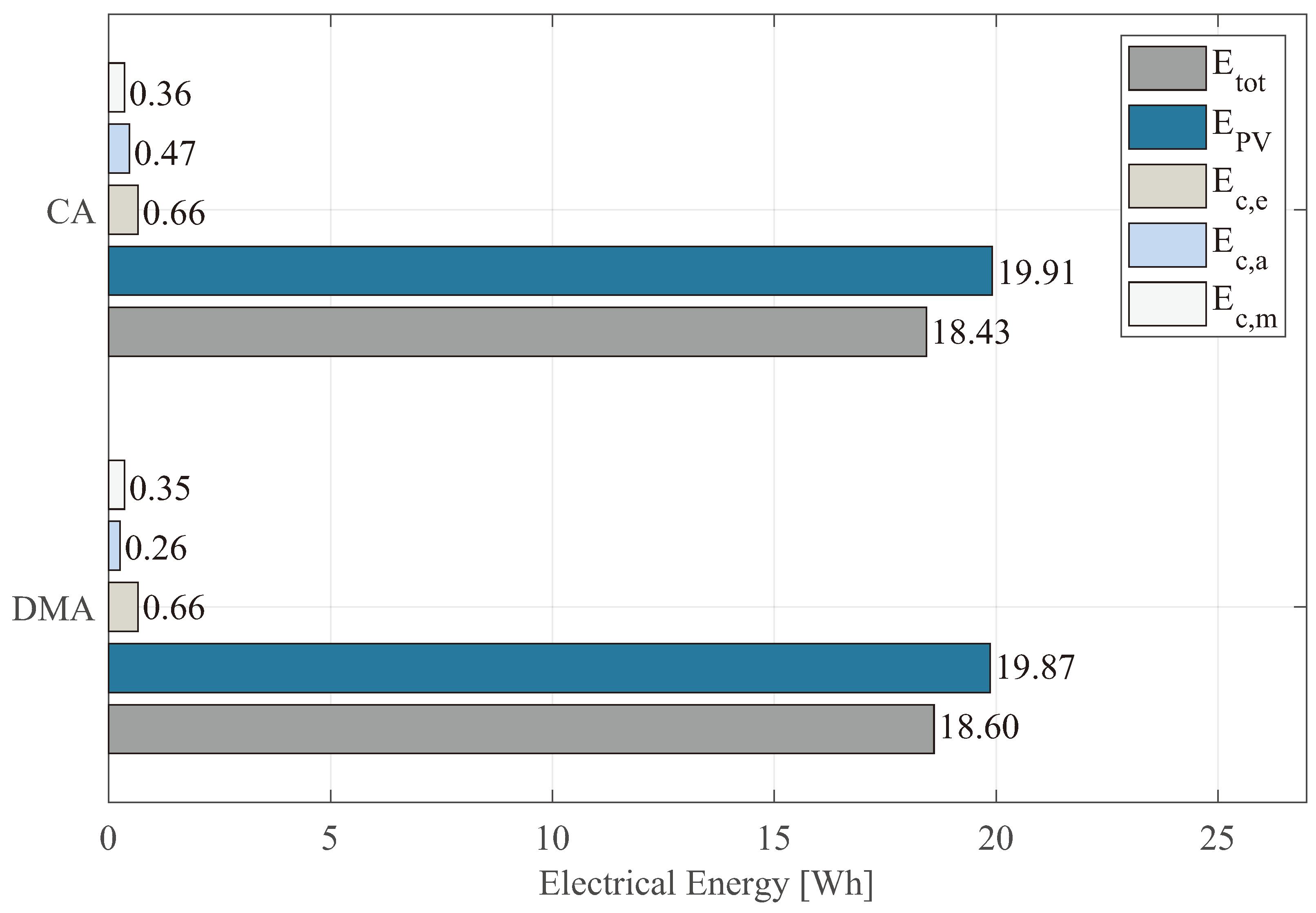
| DMA | 1.43 | 4.39 | 4.61 | 19.87 | 1.27 | 18.60 |
| CA | 0.27 | 1.00 | 1.03 | 19.91 | 1.49 | 18.43 |
| Step | Solar Time | CA | DMA | ||
|---|---|---|---|---|---|
| [°] | [Nm] | [°] | [Nm] | ||
| 0 | 11:30 | 75.22 | - | 75.22 | - |
| 1 | 11:34 | 81.25 | 0.4878 | 80.13 | 0.5496 |
| 2 | 11:38 | 82.19 | 0.4357 | - | - |
| 3 | 11:42 | 83.13 | 0.3835 | - | - |
| 4 | 11:46 | 84.08 | 0.3307 | - | - |
| 5 | 11:50 | 85.02 | 0.2783 | - | - |
| 6 | 11:54 | 85.96 | 0.2259 | - | - |
| 7 | 11:58 | 86.90 | 0.1734 | - | - |
| 8 | 12:02 | 87.84 | 0.1208 | - | - |
| 9 | 12:06 | 88.78 | 0.0683 | - | - |
| 10 | 12:10 | 89.73 | 0.0151 | 91.43 | 0.0862 |
| 11 | 12:14 | 90.67 | 0.0375 | 92.37 | 0.1326 |
| 12 | 12:18 | 91.61 | 0.0901 | 93.31 | 0.1851 |
| 13 | 12:22 | 92.55 | 0.1427 | 94.25 | 0.2376 |
| 14 | 12:26 | 93.50 | 0.1957 | 95.19 | 0.2912 |
| 15 | 12:30 | 94.44 | 0.2482 | 96.14 | 0.3429 |
| Algorithm | [RPM] | [Nm] | [hours] |
|---|---|---|---|
| 0.1067 | 1.8178 | ||
| 0.1067 | 3.2337 |
Disclaimer/Publisher’s Note: The statements, opinions and data contained in all publications are solely those of the individual author(s) and contributor(s) and not of MDPI and/or the editor(s). MDPI and/or the editor(s) disclaim responsibility for any injury to people or property resulting from any ideas, methods, instructions or products referred to in the content. |
© 2024 by the authors. Licensee MDPI, Basel, Switzerland. This article is an open access article distributed under the terms and conditions of the Creative Commons Attribution (CC BY) license (https://creativecommons.org/licenses/by/4.0/).
Share and Cite
Flores-Hernández, D.A.; Islas-Estrada, L.R.; Palomino-Resendiz, S.I. A Novel Tracking Strategy Based on Real-Time Monitoring to Increase the Lifetime of Dual-Axis Solar Tracking Systems. Appl. Sci. 2024, 14, 8281. https://doi.org/10.3390/app14188281
Flores-Hernández DA, Islas-Estrada LR, Palomino-Resendiz SI. A Novel Tracking Strategy Based on Real-Time Monitoring to Increase the Lifetime of Dual-Axis Solar Tracking Systems. Applied Sciences. 2024; 14(18):8281. https://doi.org/10.3390/app14188281
Chicago/Turabian StyleFlores-Hernández, Diego A., Luis R. Islas-Estrada, and Sergio I. Palomino-Resendiz. 2024. "A Novel Tracking Strategy Based on Real-Time Monitoring to Increase the Lifetime of Dual-Axis Solar Tracking Systems" Applied Sciences 14, no. 18: 8281. https://doi.org/10.3390/app14188281
APA StyleFlores-Hernández, D. A., Islas-Estrada, L. R., & Palomino-Resendiz, S. I. (2024). A Novel Tracking Strategy Based on Real-Time Monitoring to Increase the Lifetime of Dual-Axis Solar Tracking Systems. Applied Sciences, 14(18), 8281. https://doi.org/10.3390/app14188281