Article

Mesostructural Model for the Fatigue Analysis of Open-Cell Metal Foams

1
School of Construction and Transportation Engineering, Pontificia Universidad Católica de Valparaíso, Valparaíso 2340025, Chile
2
Department of Structural and Geotechnical Engineering, Pontificia Universidad Católica de Chile, Santiago 8320165, Chile
*
Authors to whom correspondence should be addressed.
Appl. Sci. 2024, 14(18), 8527; https://doi.org/10.3390/app14188527
Submission received: 6 August 2024 / Revised: 6 September 2024 / Accepted: 19 September 2024 / Published: 22 September 2024

Abstract

:
Metallic foams exhibit unique properties that make them suitable for diverse engineering applications. Accurate mechanical characterization is essential for assessing their performance under both monotonic and cyclic loading conditions. However, despite the advancements, the understanding of cyclic load responses in metallic foams has been limited. This study aims to propose a mesostructural model to assess the fatigue behavior of open-cell metal foams subjected to cyclic loading conditions. The proposed model considers the previous load history and is based on the analogy of progressive collapse, integrating a finite element model, a fatigue analysis model, an equivalent number of cycles model, and a failure criterion model. Validation against experimental data shows that the proposed model can reliably predict the fatigue life of the metallic foams for specific strain amplitudes.

1. Introduction

Metallic foams are contemporary materials that have been introduced into various engineering fields in a short time due to their favorable physical and mechanical properties, making them desirable for different engineering applications [1,2,3]. The properties of these materials depend directly on the base metal that comprises them, and on physical properties such as density and the configuration of foam cells. Regardless of the base metal from which the foam is made, its stiffness-to-weight ratio is suitable, and it exhibits a high energy absorption capacity, high impact resistance, and significant deformation under compressive loads [4]. Metallic foams initially found applications in aerospace [5] and automotive industries [6] due to their mechanical properties. Today, their use has diversified into areas such as biomedicine [7] and civil engineering [8], where they offer significant advantages when compared with other materials and are versatile in terms of their applications.
Mechanical characterization of metallic foams allows evaluating the response to monotonic or cyclic loading conditions. Previous research has mainly focused on the response to monotonic or unreversed cyclic loading conditions [9,10,11,12,13]. Nevertheless, the response to reversible cyclic loads, such as tensile-compression loading situations, has not been well understood until recently. Ingraham et al. [14] studied the mechanical behavior of closed-cell foams under fatigue loading, proposing a failure criterion for closed-cell foams subjected to reversible loads. Pinto et al. [15,16,17,18] studied the mechanical behavior and damage accumulation of open- and closed-cell foams under fatigue loading, proposing different models, such as failure criteria, damage accumulation, and fatigue analysis models. The mechanical characterization of metallic foams under cyclic loading conditions is necessary to consider their use in mechanical and civil engineering applications, such as in bridges and seismic protection elements.
In addition to fatigue characterization, the dynamic behavior of metallic foam sandwich structures (MFSBs) has also been investigated for their potential applications in protective equipment. Recent studies employing nonlinear finite element models have examined how these structures respond to repeated impacts, revealing that factors such as impact location and face thickness significantly influence the overall deformation, loading, and unloading stiffness of the MFSBs [19]. Furthermore, the dynamic behavior of aluminum foam sandwich beams (AFSBs) under repeated impact loadings, particularly in marine structures, has been explored, showing how cumulative damage significantly alters their deformation patterns and energy absorption capabilities [20]. These findings highlight the importance of understanding both static and dynamic responses of metallic foams for comprehensive structural design and safety applications.
In [21], aluminum foams are highlighted for their unique combination of structural properties and cost-effective manufacturing processes. The study introduces a beam finite element (FE) model based on the Kelvin cell to efficiently simulate open-cell aluminum foams. The model’s elastic properties are calibrated using the NSGA-II genetic algorithm, enabling it to accurately replicate the orthotropic behavior of the foams while minimizing computational demands. This method provides a precise and time-efficient alternative to traditional, more complex 3D models.
Moreover, the mechanical properties and energy absorption capabilities of open-cell aluminum foams have been investigated in the context of hypervelocity impacts (HVIs), which are particularly relevant in space applications. Numerical simulations based on Voronoi tessellation models have shown that these foams exhibit high accuracy in predicting shock-wave behavior, stress–strain responses, and energy dissipation under extreme impact conditions [22]. These results extend the understanding of metallic foams beyond conventional loading scenarios, emphasizing their potential in high-performance, protective applications where extreme impact resistance is required.
This study aims to propose a mesostructural model to assess the fatigue behavior of open-cell metal foams subjected to cyclic loading conditions. The model leverages the concept of progressive collapse, where ligaments within the foam structure are sequentially removed as they fail under cyclic loads. It integrates a finite element model to accurately capture the stress distribution in each ligament, a fatigue analysis model based on the Weibull distribution to predict fatigue life, an equivalent number of cycles model to account for the cumulative effects of prior loading, and a failure criterion model that considers the gradual deterioration of mechanical properties over time. By incorporating these elements, the model provides a detailed representation of the complex fatigue behavior of open-cell metal foams. The accuracy and reliability of the model are validated against experimental data, underscoring its potential utility in the design and analysis of engineering structures that utilize these materials.
The paper is structured as follows: Section 2 presents the metal foam considered for this research; Section 3 presents the proposed mesostructural model as well as all the models and approaches needed to implement the model; Section 4 presents a model application and discusses the performance of the model in comparison with experimental data; and, finally, Section 5 presents the conclusions of the research.

2. Metal Foam

Metal foams can be classified as open-cell and closed-cell foams based on their manufacturing process and respective usage. As can be seen Figure 1, a main difference between both types of cells is that closed-cell foams have ligaments and faces of the base material, as shown in Figure 1b, whereas open-cell foams only have ligaments of the base material (Figure 1a). Both types of foams exhibit different properties depending on cell geometry, relative density, and their base solid properties. The model proposed in this research is for open-cell foams [18].

3. Proposed Model

The philosophy behind the proposed model is to determine the fatigue life of the foam by analyzing the fatigue life of its ligaments. Various models are employed to develop the proposed model: a finite element model, a fatigue analysis model, an equivalent number of cycles model, and a failure criterion model. Next, each model is described.
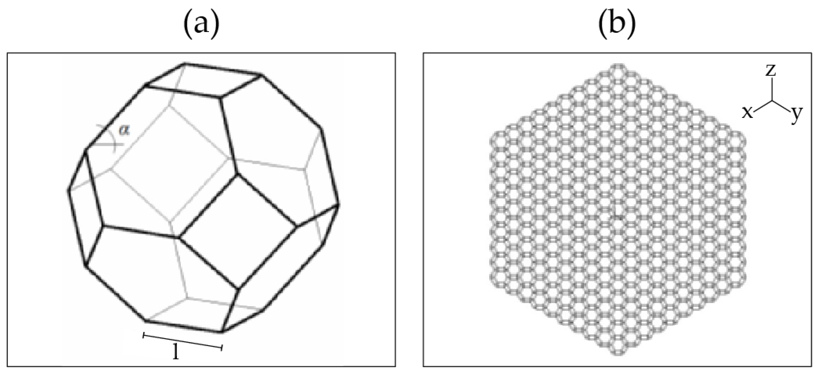
Computational methods: the proposed model considers a basic tetrakaidekahedral unit cell composed of linear ligaments forming a three-dimensional structure, as shown in Figure 2a. Each three-dimensional structure conforms to the 3-D arrangement for modeling the metal foam, as indicated in Figure 2b. Then, the stress in each ligament is evaluated.
The material properties used in the computational analysis (Duocel® foam, ERG Aerospace Corporation, Oakland, CA, USA) were derived from experimental data obtained from open-cell aluminum foams with 40 pores per inch (ppi), as detailed in our previous study. The base material for the foam is 6061 aluminum alloy, which exhibits a relative density of 6–8%. The Young’s modulus, Poisson’s ratio, and other relevant mechanical properties are measured in both compression and tension tests, ensuring accurate representation in the simulations. These properties are input into the computational models to simulate the realistic behavior of the foam under cyclic loading conditions.
The boundary conditions in the computational models were carefully chosen to reflect the experimental setup. The models employ fixed boundary conditions at the base of the foam structure to simulate a constrained scenario, while the top surface is subjected to a cyclic load. The load is applied as a fully reversed strain-controlled cycle with amplitudes ranging from 0.003 to 0.0125, mimicking the experimental fatigue tests. The cyclic load is uniformly distributed across the surface, ensuring consistent stress and strain distribution throughout the foam structure. This approach allows us to replicate the stress–strain behavior observed in physical tests, providing a reliable basis for evaluating the fatigue life of the foam under varying strain amplitudes.
Fatigue analysis model: the proposed model considers a fatigue analysis using the Weibull fatigue model, which is based on a probabilistic approach and has been used and calibrated by Pinto et al. [23] and Castillo et al. [24,25,26]. The Weibull fatigue model can be expressed as follows:
N * = exp B + λ + δ log ( 1 p ) 1 / β log ε a * C
where N * is the number of cycles to failure, p is the probability of failure, ε a is the strain amplitude, B and C are the threshold parameters, while β , λ , and δ are Weibull parameters. The detailed derivation of the Weibull model can be seen in [23,24,25,26].
Equivalent number of cycles model: estimating the number of cycles to failure becomes a variable amplitude fatigue analysis because the ligaments that have reached failure must be removed and, therefore, the stress recalculated. In this research, we use the equivalent number of cycles model, which is obtained from the Weibull model detailed in Pinto et al. [27]. The equivalent number of cycles model can record the previous history of the loads applied to the material, and it is calculated as follows:
N eq * = exp B + ( log ( n 1 ) B ) ( log ( σ 1 ) C ) log ( σ 2 ) C
where N eq * corresponds to the equivalent number of cycles applied at σ 2 that generate the same damage level as n 1 cycles applied at σ 1 .
Failure criterion model: this study considers a failure criterion model related to calculating the fatigue life of foam. This criterion is founded on the idea that a material’s mechanical qualities deteriorate over time. Three failure criteria are considered: the Ingraham et al. criterion [14], the peak compression stress reduction criterion [15], and the peak tensile stress reduction criterion [15].
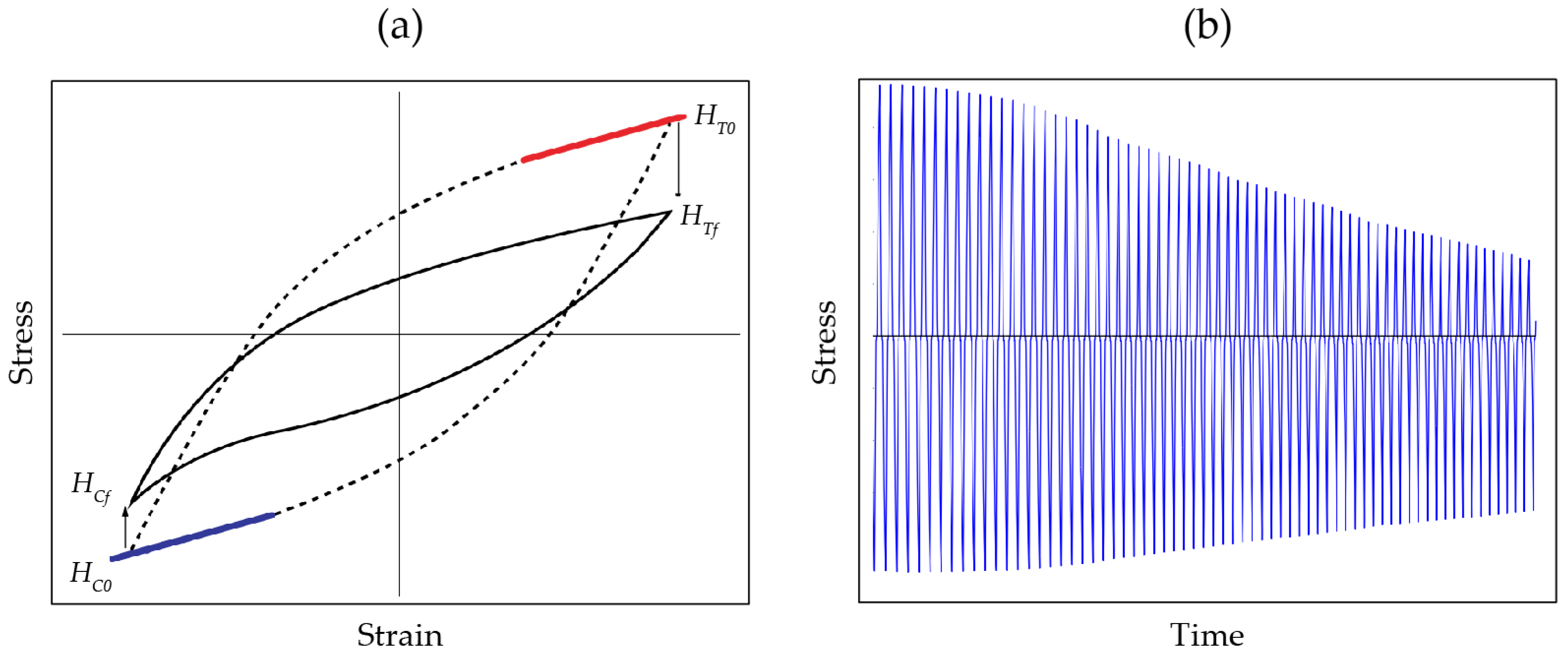
The Ingraham et al. [14] criterion established that the ratio between the prepeak tensile and prepeak compressive slope ( R = H C N H T N ) is initially close to one. As the number of cycles increases, this ratio also increases, and failure is reached when R = 1.5 . Figure 3a shows a schematic representation of the Ingraham et al. [14] criterion.
The peak compression and peak tensile stress reduction criteria [15] consider that the mechanical properties of the material decrease over its lifetime. These two criteria are defined as follows: failure is considered to have occurred when the tensile stress reaches 80 % of its maximum value or when the compressive stress reaches 90 % of its maximum value. Figure 3b shows a schematic representation of the peak compression and peak tensile stress reduction criteria [15].
Implementation of the proposed model: the proposed model is divided as follows:
Step 1: determine the stresses applied to each ligament. The finite element model is created following the basic unit cell, as shown in Figure 2a, and it is replicated in three dimensions, as shown in Figure 2b. The stresses applied to each ligament are calculated for a constant strain amplitude ( ε ) . The model allows for iterating ( i ) for each ligament ( j ) to determine the stresses applied to each ligament ( σ i j ) .
Step 2: determine the fatigue life of each ligament. A fatigue analysis is conducted for each ligament using the Weibull fatigue model (Equation (1)). The stresses applied individually are known from Step 1. As a result of the Weibull fatigue analysis, the base material S-N curve is obtained; thus, the number of cycles to failure for each stress can be determined ( n i j ) .
Step 3: identify the first ligaments to fail, remove these ligaments from the finite element model, and record the number of cycles. Since the number of cycles to failure for each ligament is known from Step 2, it is possible to determine which ligament is going to be the first to fail. The number of cycles to failure ( N i ) is given by:
N i = N i 1 + min ( n i j )
where n i j is the number of cycles to failure at iteration i of ligament j. Note that the number of cycles to failure of iteration 0 is 0 ( N i = 0 = 0 )).
At this point, it is necessary to check the failure criteria to determine if the fatigue life of the foam has been reached. If the failure criteria have been satisfied, the analysis is finished. If the failure criteria have not yet been satisfied, then the analysis continues to Step 4.
Step 4: recalculate the stresses ( σ i j ) of the remaining ligaments with the new geometric configuration in the finite element model. After new stresses are determined, the algorithm returns to Step 2; therefore, the cycles of failure for each ligament are determined and recorded as n i j .
Step 5: apply the new stresses to each remaining ligament and use the equivalent number of cycle model to determine the number of cycles remaining until each ligament’s fatigue life. The applied stresses and corresponding fatigue lives were determined for each ligament in Step 4. However, the determined number of cycles to failure must be restated according to the applied cycles.
The history of previously applied cycles is considered using the equivalent number of cycles model. This approach allows us to determine the equivalent number of cycles ( N eq j ) that generate the same amount of damage in the material for a different stress ( σ 2 ) as follows:
N eq j = exp B + ( log ( N i ) B ) ( log ( σ ( i 1 ) j ) C ) log ( σ i j ) C
Given that we have information about the number of failure cycles ( n i j ) for the new stress ( σ i j ) obtained in Step 4, it is possible to calculate the number of cycles to failure for each ligament, considering the history of previous cycles applied at different stress levels. This way, we can determine the number of cycles required for each ligament to reach failure as follows:
n j = n i j n eq j
where n j corresponds to the number of cycles to failure for each ligament considering the previous history of the ligaments, n i j is the number of cycles to failure for each ligament at a stress level without considering the previous load and cycle history, and n eq j is the equivalent number of cycles for each ligament considering the previous load and cycle history of each ligament. Next, the number of cycles to failure of the next ligament ( N * ) is determined as:
N * = min ( n j * )
Finally, the number of cycles to failure of the foam is updated by the following expression:
N = N + N *
Step 6: check the failure criteria. If the failure criteria have been satisfied, the analysis ends, and the number of cycles to failure is defined. If the failure criteria are not satisfied, the model returns to Step 3. Figure 4 shows a flow chart representation of the proposed model.

4. Application and Validation of the Proposed Model

The proposed model is validated using experimental campaign data. The experimental campaign is conducted to generate fatigue life information using open-cell metal foam for amplitude strains ranging from 0.003 to 0.0125. The base material for the foam is 6061 aluminum alloy with 40 pores per inch (ppi), subjected to a fully reversed strain-controlled cycle. More information about the experimental campaign can be found elsewhere [18].
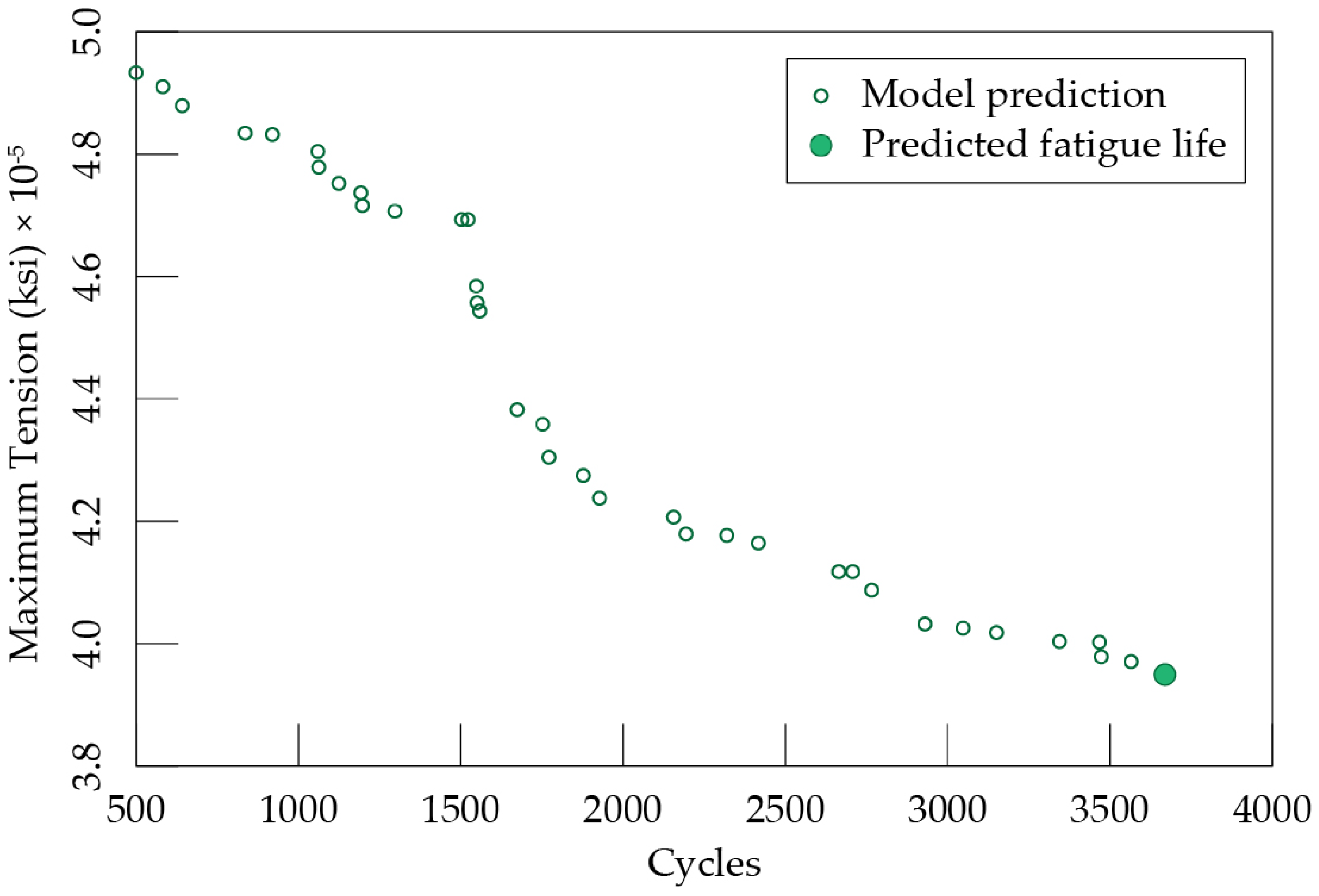
Figure 5 shows the results obtained using the proposed model, considering a constant strain amplitude of 0.003. The figure shows the relation between the maximum tension and number of cycles to failure of the open-cell metal foam. According to the proposed model, the predicted maximum tension is 3.96 × 10 5 ksi ( 80 % of 4.95 × 10 5 ksi), with a predicted fatigue life of 3600 cycles.
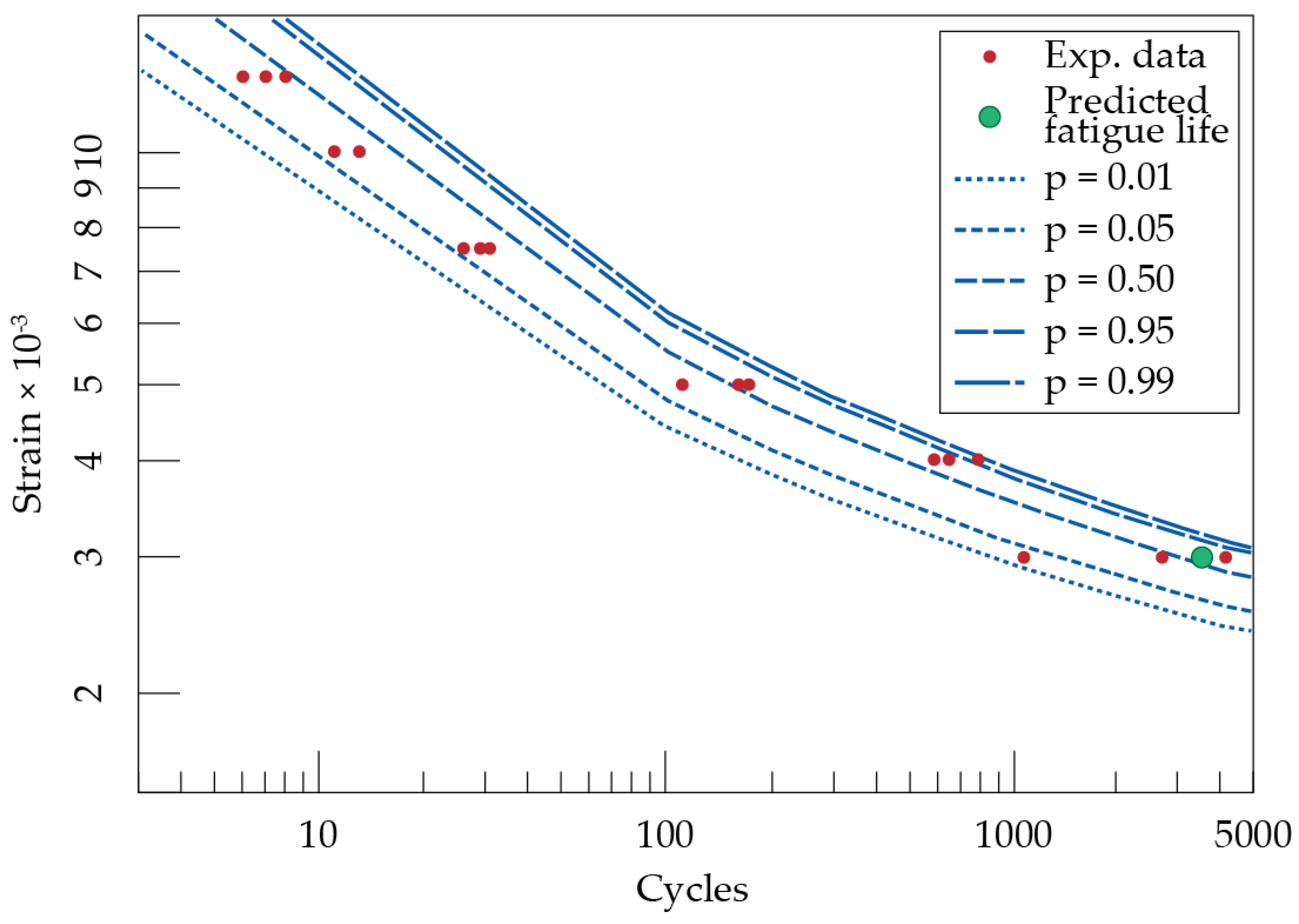
Table 1 provides a summary of the experimental results. The data in Table 1 were used in the Weibull E-N model to generate the whole E-N field curves indicated in Figure 6. Figure 6 shows the percentile curves of p = 0.01, 0.05, 0.5, 0.95, and 0.99 with blue lines. The percentile curves represent the probability of foam failure. Additionally, the experimental data of Table 1 are indicated with red dots, and the predicted fatigue life using the proposed model with a green dot.
According to Figure 6, for a strain amplitude of 0.003, the fatigue life ranges from 800 to 5000 cycles. For a probability of failure of 0.5 (p = 0.5), the fatigue life is close to 3600, which is the predicted fatigue life according to the proposed model. Therefore, the proposed model allows us to predict the fatigue life of the studied foam for a strain amplitude of 0.003. The large variation in the number of cycles to failure at this low strain amplitude is due to the inherent variability in the material’s response. At such low strain levels, small differences in the foam’s microstructure can lead to significant differences in fatigue life. Additionally, minor variations in the experimental setup, such as in loading conditions or specimen preparation, can further contribute to this variability. This behavior is consistent with observations in similar studies on metal foams under low-amplitude cyclic loading.

5. Conclusions

This research proposes a mesostructural model to assess the fatigue behavior of open-cell metal foams subjected to cyclic loading conditions. The proposed model aims to evaluate the fatigue life of the foam by considering the previous load history and the analogy of progressive collapse.
The proposed model comprises a finite element model, a fatigue analysis model, an equivalent number of cycles model, and a failure criterion model. The finite element model is based on linear ligaments forming a three-dimensional structure, recalculating the stress in each ligament remaining after removing the ligaments that have reached their respective fatigue life. The fatigue analysis model is based on a probabilistic approach and corresponds to the Weibull fatigue model. The equivalent number of cycles model is obtained from the Weibull model, recording the previous history of the loads applied to the material. The failure criterion model is based on the fact that a material’s mechanical properties deteriorate over time.
The validation of the proposed model considers experimental campaign data of open-cell metal foam subjected to a fully reversed strain-controlled cycle with a strain amplitude of 0.003. For a probability of failure of 0.5, the fatigue life is close to 3600, which is the predicted fatigue life according to the proposed model. Therefore, the proposed model allows us to predict the fatigue life of the studied foam for a specific strain amplitude.

Author Contributions

Conceptualization, H.P. and A.S.; methodology, H.P. and A.S.; software, H.P.; validation, H.P., A.S., J.G. (Jose Garcia), J.G. (Jose Gornall) and P.M.; formal analysis, H.P.; investigation, H.P. and A.S.; resources, A.P.; data curation, H.P.; writing—original draft preparation, H.P. and A.S.; writing—review and editing, H.P., A.S., J.G. (Jose Garcia) and P.M., H.A.G.; visualization, H.P.; supervision, H.P.; project administration, H.P.; funding acquisition, A.P. All authors have read and agreed to the published version of the manuscript.

Funding

José García is funded by VINCI-DI:039.463/2024.

Institutional Review Board Statement

Not applicable.

Informed Consent Statement

Not applicable.

Data Availability Statement

No new data were created or analyzed in this study.

Conflicts of Interest

The authors declare no conflict of interest.

References

  1. Taherishargh, M.; Katona, B.; Fiedler, T.; Orbulov, I.N. Fatigue properties of expanded perlite/aluminum syntactic foams. J. Compos. Mater. 2017, 51, 773–781. [Google Scholar] [CrossRef]
  2. Dineshkumar, J.; Jesudas, T.; Elayaraja, R. Characteristics, applications and processing of aluminium foams—A Review. Mater. Today Proc. 2021, 42, 1773–1776. [Google Scholar] [CrossRef]
  3. Behymer, N.; Morsi, K. Review: Closed-Cell Metallic Foams Produced via Powder Metallurgy. Metals 2023, 13, 959. [Google Scholar] [CrossRef]
  4. Smith, B.H.; Szyniszewski, S.; Hajjar, J.F.; Schafer, B.W.; Arwade, S.R. Characterization of steel foams for structural components. Metals 2012, 2, 399–410. [Google Scholar] [CrossRef]
  5. Banhart, J.; Seeliger, H.W. Aluminium foam sandwich panels: Manufacture, metallurgy and applications. Adv. Eng. Mater. 2008, 10, 793–802. [Google Scholar] [CrossRef]
  6. Cardoso, E.; Oliveira, B. Study of the use of metallic foam in a vehicle for an energy-economy racing circuit. Mater. Werkst. 2010, 41, 257–264. [Google Scholar] [CrossRef]
  7. Marin, E.; Fedrizzi, L.; Zagra, L. Porous metallic structures for orthopaedic applications: A short review of materials and technologies. Eur. Orthop. Traumatol. 2010, 1, 103–109. [Google Scholar] [CrossRef]
  8. Smith, B.; Szyniszewski, S.; Hajjar, J.; Schafer, B.; Arwade, S. Steel foam for structures: A review of applications, manufacturing and material properties. J. Constr. Steel Res. 2012, 71, 1–10. [Google Scholar] [CrossRef]
  9. Kalpakoglou, T.; Yiatros, S. Metal foams: A review for mechanical properties under tensile and shear stress. Front. Mater. 2022, 9, 998673. [Google Scholar] [CrossRef]
  10. Ashby, M.; Evans, A.; Fleck, N.; Gibson, L.; Hutchinson, J.; Wadley, H. Metal foams a design guide, Butter worth Heinemann. United States Am. 2000, 1, 119. [Google Scholar]
  11. Silva, M.J.; Gibson, L.J. The effects of non-periodic microstructure and defects on the compressive strength of two-dimensional cellular solids. Int. J. Mech. Sci. 1997, 39, 549–563. [Google Scholar] [CrossRef]
  12. McCullough, K.Y.G.; Fleck, N.A.; Ashby, M.F. The stress–life fatigue behaviour of aluminium alloy foams. Fatigue Fract. Eng. Mater. Struct. 2000, 23, 199–208. [Google Scholar] [CrossRef]
  13. Sugimura, Y.; Rabiei, A.; Evans, A.G.; Harte, A.; Fleck, N.A. Compression fatigue of a cellular Al alloy. Mater. Sci. Eng. A 1999, 269, 38–48. [Google Scholar] [CrossRef]
  14. Ingraham, M.D.; DeMaria, C.; Issen, K.; Morrison, D. Low cycle fatigue of aluminum foam. Mater. Sci. Eng. A 2009, 504, 150–156. [Google Scholar] [CrossRef]
  15. Pinto, H.; Arwade, S.R.; Veale, P. Response of open cell aluminum foams to fully reversed cyclic loading. J. Eng. Mech. 2011, 137, 911–918. [Google Scholar] [CrossRef]
  16. Pinto, H.; Arwade, S. Damage accumulation model for aluminium-closed cell foams subjected to fully reversed cyclic loading. Fatigue Fract. Eng. Mater. Struct. 2011, 34, 1021–1034. [Google Scholar] [CrossRef]
  17. Pinto, H.; Peña, Á.; Aravena, I. Exponential Model for Damage Accumulation in Closed Cell Aluminum Foams. Rev. Constr. J. Constr. 2015, 14, 80–85. [Google Scholar] [CrossRef]
  18. Pinto, H.; Amini, A.; Peña, Á.; Moraga, P.; Valenzuela, M. Fatigue and damage accumulation in open cell aluminium foams. Fatigue Fract. Eng. Mater. Struct. 2018, 41, 483–493. [Google Scholar] [CrossRef]
  19. Guo, K.; Mu, M.; Zhou, S.; Zhang, Y. Dynamic responses of metal foam sandwich beam under repeated impacts considering impact location and face thickness distribution. Compos. Part C Open Access 2023, 11, 100372. [Google Scholar] [CrossRef]
  20. Guo, K.; Mu, M.; Zhou, S. Investigation on the dynamic behaviors of aluminum foam sandwich beams subjected to repeated low-velocity impacts. Metals 2023, 13, 1115. [Google Scholar] [CrossRef]
  21. Belardi, V.; Trupiano, S.; Fanelli, P.; Vivio, F. Overall elastic characterization of equivalent FE models for aluminum foams through computational homogenization approach and genetic algorithm optimization. Eur. J. Mech. A/Solids 2024, 103, 105189. [Google Scholar] [CrossRef]
  22. Zhao, S.; Zhang, X.; Wang, R.; Li, R. Stress-strain states and energy absorption in open-cell aluminium foams under hypervelocity impact. Compos. Struct. 2023, 313, 116885. [Google Scholar] [CrossRef]
  23. Pinto, H. Models for Crack Propagation and Fatigue Analysis Based on Strain and Stress Life Data. Applications. Ph.D. Thesis, University of Cantabria, Santander, Spain, 2009. [Google Scholar]
  24. Castillo, E.; Fernández-Canteli, A.; Hadi, A.; López-Aenlle, M. A fatigue model with local sensitivity analysis. Fatigue Fract. Eng. Mater. Struct. 2007, 30, 149–168. [Google Scholar] [CrossRef]
  25. Castillo, E.; Fernández-Canteli, A.; Pinto, H.; López-Aenlle, M. A general regression model for statistical analysis of strain–life fatigue data. Mater. Lett. 2008, 62, 3639–3642. [Google Scholar] [CrossRef]
  26. Castillo, E.; Fernández-Canteli, A. A general regression model for lifetime evaluation and prediction. Int. J. Fract. 2001, 107, 117–137. [Google Scholar] [CrossRef]
  27. Pinto, H.; De Jesus, A.M.; Fernández-Canteli, A.; Castillo, E.; Pereira, H.F. Analysis of constant and variable amplitude strain-life data using a novel probabilistic Weibull regression model. J. Press. Vessel Technol. 2010, 132, 061401. [Google Scholar] [CrossRef]
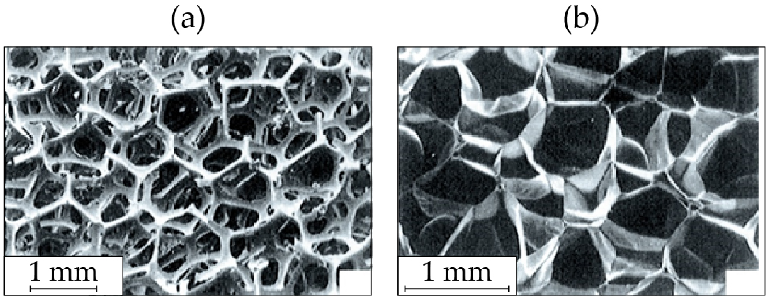
Figure 1. Metal foams: (a) open-cell foam and (b) closed-cell foam.
Applsci 14 08527 g001
Figure 2. (a) Basic unit cell and (b) 3-dimensional arrangement for modeling the metal foam.
Applsci 14 08527 g002
Figure 3. Schematic representation of the proposed failure criteria: (a) Ingram et al. criterion [14] and (b) peak compression and peak tensile stress reduction criteria [15].
Applsci 14 08527 g003
Figure 4. Flow chart of the proposed model.
Applsci 14 08527 g004
Figure 5. Proposed model prediction: maximum tension versus number of cycles to failure of the open-cell metal foam with a strain amplitude of 0.003.
Applsci 14 08527 g005
Figure 6. E-N curve for the studied metallic foam.
Applsci 14 08527 g006
Table 1. Strain amplitude vs. number of cycles to failure.
Strain AmplitudeNumber of Cycles to Failure
0.003407627061069
0.004589786690
0.005111173161
0.0075312926
0.01111311
0.0125678
Disclaimer/Publisher’s Note: The statements, opinions and data contained in all publications are solely those of the individual author(s) and contributor(s) and not of MDPI and/or the editor(s). MDPI and/or the editor(s) disclaim responsibility for any injury to people or property resulting from any ideas, methods, instructions or products referred to in the content.