Article

Optimizing the Landing Stability of Blended-Wing-Body Aircraft with Distributed Electric Boundary-Layer Ingestion Propulsors through a Novel Thrust Control Configuration

1
Research Institute of Aero-Engine, Beihang University, Beijing 102206, China
2
School of Transportation Science and Engineering, Beihang University, Beijing 102206, China
*
Author to whom correspondence should be addressed.
Appl. Sci. 2024, 14(18), 8546; https://doi.org/10.3390/app14188546
Submission received: 24 June 2024 / Revised: 8 September 2024 / Accepted: 17 September 2024 / Published: 23 September 2024
(This article belongs to the Section Aerospace Science and Engineering)

Abstract

:
The imperative for energy conservation and environmental protection has led to the development of innovative aircraft designs. This study explored a novel thrust control configuration for blended-wing-body (BWB) aircraft with distributed electric boundary-layer ingestion (BLI) propulsors, addressing the issues of sagging and altitude loss during landing. The research focused on a small-scale BWB demonstrator equipped with six BLI fans, each with a 90 mm diameter. Various thrust control configurations were evaluated to achieve significant thrust reduction while maintaining lift, including dual-layer sleeve, separate flap-type, single-stage linkage flap-type, and dual-stage linkage flap-type configurations. The separate flap-type configuration was tested through ground experiments. Control experiments were conducted under three different experimental conditions as follows: deflection of the upper cascades only, deflection of the lower cascades only, and symmetrical deflection of both cascades. For each condition, the deflection angles tested were 0°, 10°, 20°, 30°, 40°, 50°, and 60°. The thrust reductions observed for these three conditions were 0%, 37.5%, and 27.5% of the maximum thrust, respectively, without additional changes in the pitch moment. A combined thrust adjustment method maintaining a zero pitch moment demonstrated a linear thrust reduction to 20% of its initial value. The experiment concluded that the novel thrust control configuration effectively adjusted thrust without altering the BLI fans’ rotation speed, solving the coupled lift–thrust problem and enhancing BWB landing stability.

1. Introduction

In contemporary times, under the pressing need for energy conservation and environmental safeguarding, the aviation industry faces the dual challenge of reducing emissions and accommodating increasing passenger volumes. Against this backdrop, the concept of green aviation has emerged as a universal consensus in this field. Historically, the conventional methodology in aircraft operation often considered the airframe and the propulsion system as distinct components. This compartmentalized perspective has led to the optimization of aviation engine architectures to the point where propulsion efficiencies are approaching their peak, resulting in a scenario where the benefits of further technological enhancements are becoming progressively nominal [1,2,3]. Advancements in the aviation industry are now focused on the development of aircraft that are aerodynamically superior, environmentally benign, low in carbon emissions, highly stable, capable of bearing significant payloads, and economically viable [4,5,6]. Aircraft featuring boundary-layer ingestion (BLI) fans within a blended wing body (BWB) and incorporating distributed propulsion mark a pivotal development in the realm of next-generation civil aviation. These aircraft, by integrating the boundary layer, can achieve dramatically enhanced overall aerodynamic characteristics through the synergistic interaction between the aircraft and engine, while also diminishing noise and fuel consumption [7,8,9]. Furthermore, distributed propulsion systems are increasingly being merged with electric propulsion technologies. Their novelty resides in the use of electrically driven propulsors, which are exclusively connected through electrical channels to energy sources or power generation systems. This enables more flexible positioning, design, and operation of propulsors, exploiting the combined advantages of aerodynamics and propulsion integration, yielding a superior performance compared to conventional designs [10,11]. Currently, BWB aircraft with distributed electric BLI fans represent a prime area of investigation in the field of cutting-edge global aviation technology.
In the field of BWB aircraft research, Brown et al. [12] developed a method comparing BWB aircraft to traditional tube-and-wing designs and highlighted the BWB aircraft′s advantages in mass, aerodynamics, and fuel economy. Niu et al. [13] explored BWB aileron surface flow through simulations and tests, enhancing the flow state with Krueger flaps without affecting the aerodynamics. Ammar et al. [14] analyzed a 200-passenger BWB aircraft′s design and stability, and challenges were noted due to the lack of a vertical tail compared to an A320. Yu and Duan [15] achieved an improved aerodynamic performance for a 300-seat BWB design at Mach 0.85 using winglets and Krueger flaps. Kleemann et al. [16] demonstrated the enhanced flight performance of a solar–electric BWB for general aviation with a lower maximum takeoff mass. Wang and Zhou [17] validated an aerodynamic design method for a small BWB UAV through wind tunnel tests. Mv et al. [18] emphasized a 3D BWB model′s aerodynamic efficiency and environmental benefits. Hossan and Srinivas [19] assessed a BWB re-entry vehicle′s aerodynamics, finding the optimal conditions for high angles of attack and Mach numbers. Agarwal et al. [20] presented a CAD-based aerodynamic optimization framework, achieving significant drag reduction while maintaining lift.
Concentrating on studies related to BLI, Kerho [21] explored the aero-propulsive coupling of BLI fans on wings, crucial for turboelectric distributed propulsion (TeDP) systems such as NASA′s NX-3, proposing challenges and advantages including an effective bypass ratio and safety. Urban et al. [22] investigated the impact of electric ducted fans′ (EDFs) structural arrangement on air transport electrification, finding increased outlet cross-sections to be beneficial for vertical thrust, positioning EDFs as a viable option for unmanned aircraft propulsion. Zhao et al. [23] assessed the energy-saving potential of BLI in transonic BWB aircraft and developed a new expression for BLI′s power-saving coefficient, offering a preliminary evaluation tool for aircraft configurations. Giuliani et al. [24] extended the TURBO analysis code to include BLI inlet–fan interaction, specifically modeling a flush-mounted S-duct with significant BLI. Jia et al. [25] focused on the power fan design for BWB aircraft with distributed propulsion, examining BLI′s effect on the fan aerodynamics through simulation. Seitz et al. [26] presented insights from the CENTRELINE project, discussing the propulsive fuselage concept (PFC) and its implications for fuel burn, NOx emissions, and noise reduction. Diamantidou et al. [27] reviewed recent advances in BLI technology and addressed the challenges in evolving powertrain systems and the multidisciplinary nature of BLI. Yu et al. [28] analyzed the aerodynamic differences between flow-through nacelle (FTN) and with-powered-nacelle (WPN) engine models on the BWB300 airframe, demonstrating significant impacts of engine shape on the airframe surface flow during takeoff using 3D unsteady compressible RANS computation.
Within research on DEP, Wu et al. [29] optimized distributed electric propulsion (DEP) in general aviation aircraft, enhancing range without impacting takeoff/landing velocities. Using actuator disk theory and the vortex lattice method, their strategy focused on maximizing the lift–drag ratio and propeller efficiency, finding that strategically placed propellers in DEP aircraft improved cruise performance, but required more power for high-lift operations. Hospodář et al. [30] designed a DEP system for general aviation that reduced the fuel consumption in cruise conditions by using distributed propellers on the wing′s leading edge to increase the local dynamic pressure, thereby achieving the needed lift with a smaller wing area. Burston et al. [31] provided a critical review of advanced distributed propulsion (DP) systems, discussing their potential to improve aircraft performance, fuel efficiency, and emissions, while also emphasizing the role of digital control in thrust modulation. Zhang et al. [32] studied the aero-propulsion coupling characteristics of a DEP aircraft with EDFs along the wing′s trailing edge, showing significant lift and drag reduction, underscoring the benefits of DEP and BLI at low speeds. Wick et al. [33] examined the integration challenges and benefits of distributed propulsion in commercial and military transport, suggesting an 8% improvement in transonic efficiency compared with conventional engines. Lastly, Zhao et al. [34] explored the impact of DP on a BWB aircraft′s aerodynamics, demonstrating enhanced lift and aerodynamic power consumption and recommending inflow speed limitation to reduce power consumption and improve stall characteristics.
Focusing on BWB stability, Reist et al. [35] studied the stability and control in BWB aircraft using a multi-fidelity optimization approach, examining two BWB designs and finding a slight advantage in fin-based control. Chang et al. [36] analyzed the aerodynamics in tandem-channel wing electric vertical takeoff and landing (eVTOL) aircraft, focusing on the propeller–wing interaction and finding increased lift with an increased propeller speed and attack angle. Vechtel and Buch [37] discussed yaw control in aircraft with distributed electric propulsion, demonstrating that more engines allow for smaller tail planes and reduced fuel consumption. Chen et al. [38] assessed BWB aircraft design, emphasizing stability, control, and performance trade-offs, and suggested a static stability criterion. Paulus et al. [39] used gradient-based optimization for improved wind tunnel testing and recommended design and optimization strategies for BWB aircraft with high lift and control surfaces. Sargeant et al. [40] investigated the static stability in BWB-type aircraft with center-body leading-edge carving, showing stability across a wide range of attack angles and developing a methodology for determining the carving amount. Lou et al. [41] investigated the impact of a new thrust reverser on the aerodynamic performance of a BWB propulsion system using numerical simulations.
In the field of takeoff and landing safety research, Ye et al. [42] developed a soft switching mode for eVTOL compound-wing UAVs to enhance their robustness and safety, using dynamic inversion to mitigate lift loss during deceleration, thereby ensuring smoother transitions and better passenger comfort. Lu et al. [43] addressed the landing safety in a BWB RPV using a system-theoretic analysis to mitigate “path sagging” with a “belly-flap” control surface, which was confirmed as being effective in flight tests. Staelens et al. [44] examined the use of belly flaps in BWB airplanes to increase lift and address control challenges, which was validated by wind tunnel tests. Xin et al. [45] studied externally blown elevons in BWB aircraft, showing their efficiency over conventional elevons through CFD methods. Viviani et al. [46] evaluated the aerodynamic performance of a BWB re-entry vehicle at low speeds, providing insights into the lift performances and vortex phenomena for static stability. Chung et al. [47] used CFD to analyze the pitch control needed for landing in a blended-wing-body UCAV, exploring belly flaps to solve low-speed landing issues. Lastly, Zhou et al. [48] presented a landing safety prediction model for critical flight phases using pattern recognition, Markov chains, and a neural network with a genetic algorithm, which enhanced prediction precision.
In the landing phase, an aircraft must use thrust reversers to augment drag and decelerate the aircraft. Conventional commercial airplanes primarily employ three types of thrust reversal mechanisms, as follows: bucket, cascade, and petal. However, these thrust control configurations tend to cause aircraft to stall due to the induced airflow disturbances, which are detrimental to the maintenance of lift on the wings. These disturbances in the airflow field can engender unstable flight conditions during landing, thereby elevating the risk of stalling and reducing the landing stability of BWB aircraft.
In terms of research on thrust control, Gang Y. et al. [49] examined the use of a thrust reverser cascade in BWB300 civil airplanes; employing CFD, they found that it could be effectively applied to reduce landing distance, similar to in standard turbofan planes, but noted a design trade-off with an increased reverse mass flow and closing velocity. Zhao J. et al. [50] delved into the dynamic modeling of this mechanism, noting nonlinearities due to clearance and flexibility; they highlighted that joint clearance and flexible parts affect the kinematics, dynamics, and vibration of the system, underscoring the importance of actuator synchronization.
BLI fans, located on the upper surface of the aircraft, can ingest boundary-layer air, increasing the airflow velocity over the wings and reducing the pressure on the upper surface, thereby providing additional lift. However, BWB aircraft with distributed electric BLI propulsors face challenges in thrust control during landing, primarily due to the tight coupling between lift and thrust caused by the ingestion of boundary-layer air by the BLI fans. Additionally, due to their high aspect ratio and lack of flaps for lift enhancement, BWB aircraft commonly experience issues such as descent and altitude loss during deceleration and landing. The traditional solution to this is to adjust the thrust by regulating the flow rate of the BLI fans, but this reduces the boundary-layer ingestion effect, leading to a loss of lift and affecting the pitch moment in BWB aircraft, which have short lever arms. As a result, maintaining additional lift and pitch moment during landing is crucial to improving the stability and safety of these aircraft during the landing phase.
To address the issue of descent and altitude loss in BWB aircraft with distributed electric BLI propulsors during the landing phase, this paper proposes a novel thrust control configuration located behind the BLI propulsors, based on a comparison of various thrust control schemes. The core concept is to maintain the lift and pitch moment while simultaneously reducing the thrust. This is achieved through a series of thrust control cascades that function similarly to spoilers. These cascades alter the direction of the airflow at the fan exit, increasing aerodynamic drag and reducing the aircraft′s speed without changing the flow rate of the BLI fans. By maintaining the speed of the BLI fans, the boundary-layer ingestion effect remains constant, preserving the additional lift and thereby enhancing the stability of BWB aircraft with short lever arms during landing. This study involves a comparative analysis, numerical simulations, and ground tests, culminating in a thrust control configuration that maintains lift across all operational conditions, particularly improving the landing stability of BWB aircraft.

2. Overcoming Sagging and Altitude Loss Problems: Effective Solutions

2.1. Sagging and Altitude Loss Problems of BWB Aircraft

In BWB aircraft design, a prominent challenge pertains to the management of short-coupled control systems. As shown in Figure 1, the distance from the lever arm of the control surface to the center of gravity (CG) in BWB designs is from approximately two to three times shorter than that in conventional aircraft designs. This shorter lever arm necessitates a greater downward force to achieve the desired pitch-up moment, which is opposite to the direction of lift. Such a configuration often results in the aircraft experiencing descent during the takeoff and landing phases, referred to as “sagging” by NASA [51], before achieving the desired pitch angle. This short lever arm length can adversely affect the control of the flight path, especially during critical phases such as landing. Consequently, adjustments in pitch are often accompanied by an unwarranted decrease in altitude, posing a risk to flight safety.
In addition, aircraft flight requires the appropriate thrust for different flight phases. Traditional aircraft alter their thrust by changing the engine flow rates. In BWB aircraft with distributed BLI propulsors, the suction effect of BLI fans can provide additional lift, so conventional methods of thrust control present a novel, tightly coupled problem, where the additional lift from boundary-layer suction diminishes as the airflow through the BLI fans decreases, which causes an altitude loss problem. Thus, as the thrust is reduced in the landing phase, a decrease in the flow rate results in reduced suction, leading to a decrease in additional lift and a deterioration in the delay of airflow separation, compromising the aircraft′s safety and stability.

2.2. Effective Thrust Control Configuration for BWB Aircraft

The research subject selected for this study is a self-constructed small-scale BWB demonstrator, a schematic model of which is illustrated in Figure 2. This model integrates a BWB design with distributed propulsion, featuring six small BLI fans, each with a diameter of 90 mm, strategically positioned along the wingspan at the upper trailing edge of the fuselage.
In the following design of thrust control configuration, the fundamental approach to addressing the tightly coupled relationship between thrust and lift involves controlling the thrust by altering the direction of the airflow while maintaining a constant airflow intake, without reducing the aircraft′s lift. Furthermore, ensuring minimal changes in the overall pitch moment of the aircraft during continuous thrust control is given priority consideration. Four potential thrust control configurations were designed to solve the sagging and altitude loss problems of BWB aircraft, which are described in detail in Section 2.2.1, Section 2.2.2, Section 2.2.3 and Section 2.2.4.

2.2.1. A Dual-Layer Sleeve Thrust Control Configuration

A dual-layer sleeve thrust control configuration operates based on its innovative structural design, allowing for precise manipulation of the airflow through the propulsion unit. As illustrated in Figure 3 and Figure 4, this configuration comprises the two following primary elements: the outer sleeve and the inner sleeve, supplemented by a thrust control cascade affixed to the outer sleeve. The outer sleeve envelops the airflow channel, facilitating uninterrupted airflow through the propulsion unit. When an adjustment in thrust is necessitated, the outer sleeve moves backward, revealing the airflow passage on the inner sleeve. This retraction alters the path of the airflow, consequently reducing the volume of air passing through the primary propulsion unit, thereby modulating the thrust. Additionally, the thrust control cascade, attached to the top end of the outer sleeve, moves in tandem with it, effectively obstructing a portion of the airflow, thereby fine-tuning the quantity of air passing through. The movement of the outer sleeve causes the connecting rod to pull the blocker doors towards the inner shaft, positioning the thrust control plate in a fully closed state, as shown in Figure 3b. The airflow is expelled through the channel in the cascade.

2.2.2. A Separate Flap-Type Thrust Control Configuration

A separate flap-type thrust control configuration, as illustrated in Figure 5 and Figure 6, can be installed behind the BLI propulsors, covering the entire propulsion system with thrust control cascades. This configuration operates by utilizing movable cascades to regulate the airflow passing through the propulsion system. In the normal thrust mode, as depicted in Figure 6, the movable cascades are aligned along the same plane as the fixed cascades, ensuring that the airflow passes parallel to these cascades. Once in the reverse thrust mode, when the movable cascades on the DF and D′ F′ sides deflect, a space between them opens up, creating a new exhaust channel. This channel does not pass directly through the central part of the propulsion system, but rather through the lateral passages formed by the cascades, such as points A, F, and A′, F′, as indicated in Figure 6. This redirection allows the airflow to exit at various angles, effectively reducing the direct aft thrust, aiding in the deceleration of the aircraft during the landing phase.

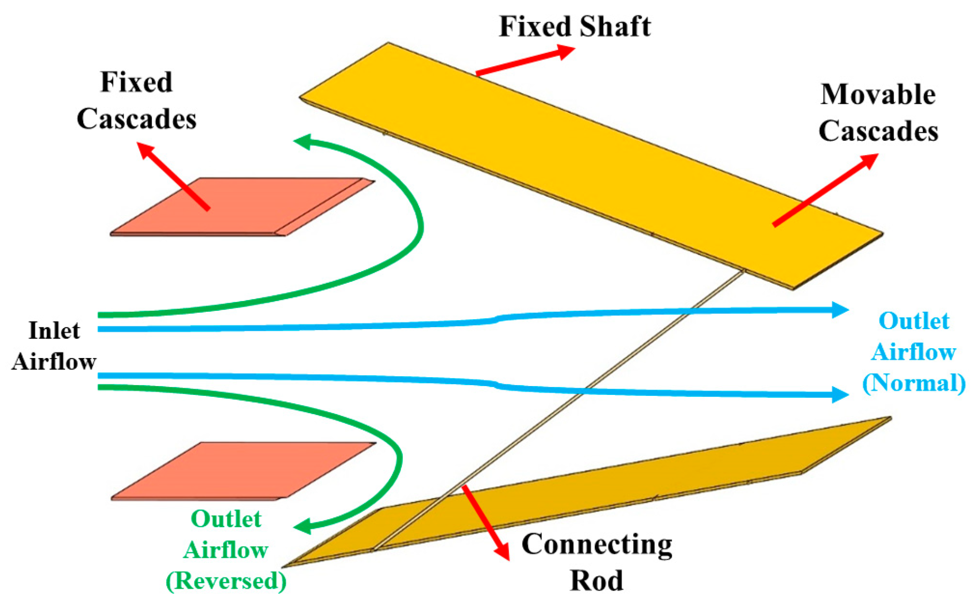
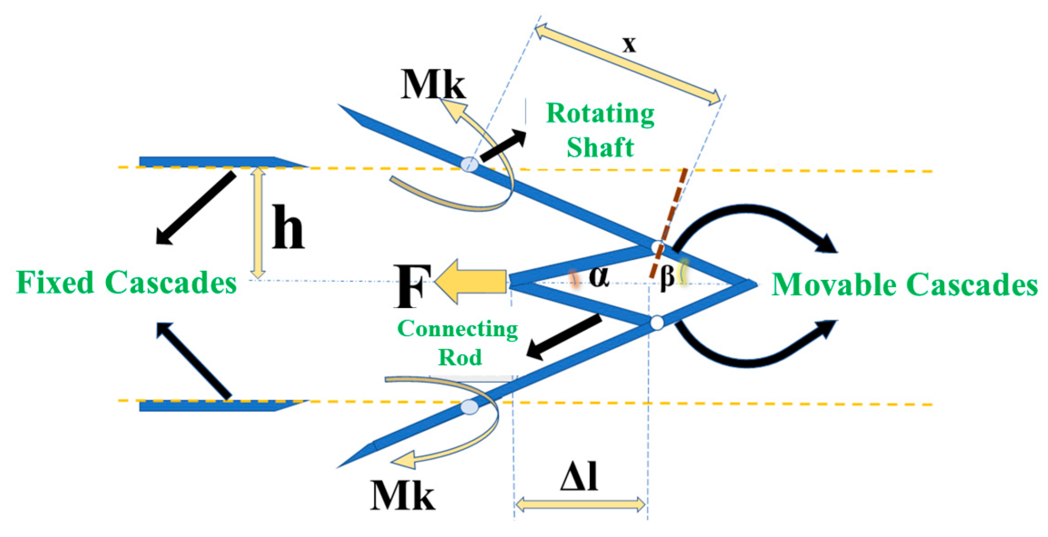
2.2.3. A Single-Stage Linkage Flap-Type Thrust Control Configuration

As delineated in Figure 7 and Figure 8, a single-stage linkage flap-type thrust control configuration is similar to the separate system described in Section 2.2.2. However, a distinctive feature of this system is that the two movable cascades are linked and can only move in unison, not independently. The system′s design is predicated on a servo motor, which confers kinetic energy to the lower cascades. A pivotal element of its mechanism is the connecting rod that transmits the rotational movement initiated by the servo at the lower cascades to the upper ones. The fixed shaft serves as the fulcrum of the cascades, allowing for precise angular adjustments. Mk1 refers to the moment caused by air pressure on the upper cascade during flight, while Mk2 represents the moment produced by the air on the lower cascade. Additionally, Md describes the moment generated by compression when the flap is fully closed.

2.2.4. A Dual-Stage Linkage Flap-Type Thrust Control Configuration

Figure 9 and Figure 10 illustrate a dual-stage linkage flap-type thrust control configuration. This complex arrangement utilizes a servo mechanism that connects to both upper and lower movable cascades via a dual-stage linkage. This linkage not only transmits motion, but also amplifies the input from the servo to achieve a greater range of cascade deflection. The rotating shaft plays a central role in orchestrating the movements of the movable cascades. Consistent with the description provided earlier, in the normal thrust mode, the moveable cascades align with the fixed cascades along the same plane, allowing the airflow to pass parallel to this plane. In contrast, during the reverse thrust mode, the moveable cascades form an angle with the fixed cascades, directing the airflow through this angled channel. The presence of two variable angles, α and β, enables a versatile range of motion, allowing for more refined adjustments to the angle of the cascades. Here, the linkage′s dual stages are critical for enhancing the mechanical advantage, which is further influenced by the torque (Mk) and changes in the length (Δl) of the linkage arms.

2.2.5. Summary of Thrust Control Configuration

In summary, the dual-layer sleeve thrust control configuration offers good sealing and minimal air leakage, but its complex structure poses significant manufacturing challenges and the impact of circumferential airflow is considerable, rendering it unsuitable for distributed propulsion systems with a high propulsion unit density. The single-stage linkage flap-type thrust control configuration has a simple drive mechanism and easy operation, but its deflection process is asymmetric, requiring the greatest torque when fully closed, leading to uncontrollable asymmetry. The dual-stage linkage flap-type thrust control configuration, while straightforward in drive and operation, is heavy and incapable of asymmetric deflection. Both configurations with a flap-type linkage are limited in thrust control because they can only undergo symmetric or asymmetric deflection. The separate flap-type thrust control configuration, with its separate transmission mechanism, is less challenging to manufacture and is capable of asymmetric combined control; this configuration is selected as the final solution.
As illustrated in Figure 11, a separate flap-type thrust control configuration is integrated into the aft section of an (BWB) aircraft, as depicted in Figure 6. The elevator is relocated to the upper part of the vertical stabilizer, and an additional lift propulsion system is installed at the original elevator position. The thrust control configuration comprises fixed cascades above the propulsion system and movable cascades affixed to both sides of the propulsors. The airflow is ingested through the BLI fans via the airflow passage formed between the fixed cascades and the aircraft body. The outlet airflow passes through the movable cascades of the thrust control configuration. By adjusting the deflection angle of the movable cascades, the drag regulation of the aircraft is achieved, while maintaining the lift and pitch moment.

3. Analytical Model and Experimental Setup

3.1. Analytical Model

This section defines the coordinate system and aerodynamic parameters employed in this study. The coordinate system used is the airflow coordinate system (wind axis system) O–xa–ya–za, as depicted in Figure 12. The origin of the coordinates is located at the center of mass of the aircraft. In this system, the O–xa axis is parallel to the direction of the oncoming flow, pointing towards the nose of the aircraft; the O–za axis is perpendicular to the O–xa axis, pointing downwards; and the O–ya axis is perpendicular to the O–xa–za plane, following the right-hand rule, pointing towards the right side of the aircraft. The lift (L) and drag (D) of the aircraft are defined within this wind axis system. Here, the lift, L, is considered to be positive in the negative direction of the O–za axis, the drag, D, is positive in the negative direction of the O–xa axis, and the pitch moment, M, is considered to be positive when the nose is raised, rotating about the O–ya axis.
The force model for a BWB aircraft equipped with distributed electric BLI propulsors is as follows:
Gravity: For a BWB aircraft with distributed electric BLI propulsors, gravity can be represented by a constant value.
BLI fan thrust: The thrust of the BLI fan is related to its geometric characteristics and the rotation speed, which is represented as a function of the slipstream velocity at the duct exit [52].
T = m ˙ ( V e + V ) m ˙ V
where m ˙ denotes the mass flow rate through the duct, V is the incoming flow velocity relative to the front, and Ve represents the slipstream velocity at the ducted fan exit.
The definitions for the dimensionless aerodynamic forces and moment parameters are as follows [52]:
C L = L 0.5 ρ 0 V 0 2 S ref
C D = D 0.5 ρ 0 V 0 2 S ref
C M = M 0.5 ρ 0 V 0 2 S ref c
K = C L C D
where CL, CD, and CM represent the coefficients of the lift, drag, and pitch moment, respectively. The lift-to-drag ratio is denoted as K, while ρ0 and V0 denote the density and velocity of the free-stream airflow well ahead of the aircraft, respectively. The terms L, D, and M signify the aircraft′s lift, the total drag of the aircraft, and the pitch moment, respectively. Sref refers to the total reference area of the aircraft, and c denotes the average aerodynamic chord length.

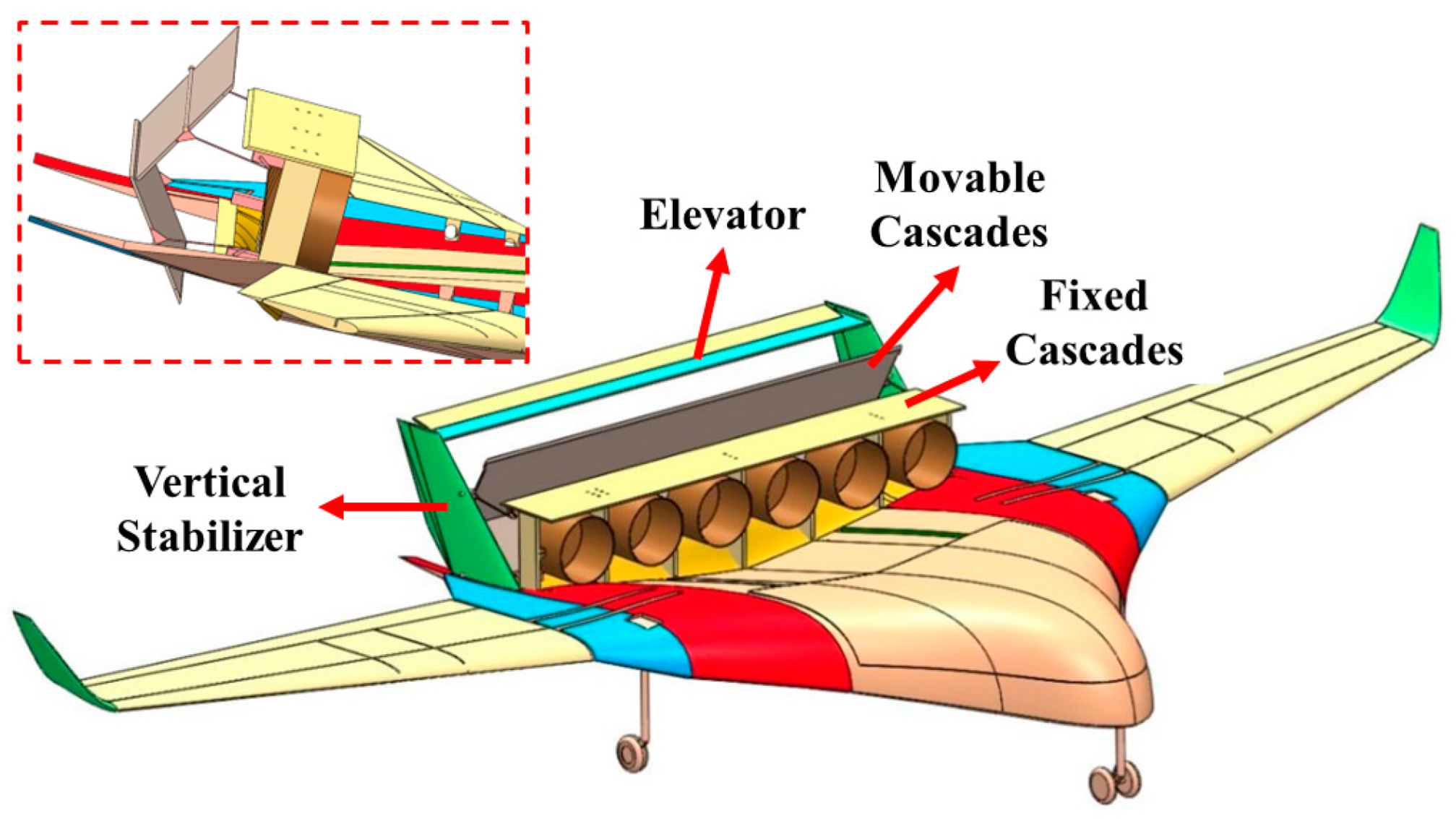
3.2. Experimental Setup

An experiment aiming to explore the effects of the thrust control configuration on the lift, thrust, and pitch moment of a BWB aircraft with distributed electric BLI propulsors was carried out. As illustrated in Figure 13, the experimental platform comprised the three following components: the BWB aircraft, aerodynamic conditions, and measurement devices. The BWB aircraft had a mass of 13.3 kg, a wingspan of 2.5 m, and a center body chord length of 0.982 m. The fuselage dimensions were 1098.41 mm in length, 2461.6 mm in width, and 387.9 mm in height. The aircraft′s reference area was 0.9663 m2, with a reference length of 0.409 m.
A high-flow-rate thrust control configuration was installed at the rear of the distributed propulsors, equipped with a fixed cascade and two moveable cascades positioned both above and below the BLI fans, each measuring 300 mm × 165 mm × 3 mm. Two high-strength carbon fiber rods with a diameter of 6 mm were installed at 80 mm from the leading edge on each of the two moveable cascades, with lightweight bearings supporting the rotating shafts. This setup allowed for the adjustment of the moveable cascade′s deflection during the experiments. A knob was used to adjust the friction between the cascades and the rotation shafts. When the deflection angle needed to be changed, the knob was rotated to reduce the friction, allowing for the cascades to be positioned at the desired deflection angle. The knob was then rotated again to increase the friction, clamping the rotation shafts and securing the cascades′ orientation, ensuring that their position remained fixed during the operation of the BLI fans. An industrial fan was used to provide an incoming flow at 4 m/s, and fine mesh screens were installed upstream of the contraction in order to reduce the turbulence and guarantee a uniform velocity distribution in the test section.
A high-precision digital thrust meter (Model SGHF-5), with a measurement range of 0.5–5 N and a resolution of 0.001 N, was employed to accurately measure the thrust force during ground tests. For the experiment, the front landing gear of the distributed propulsion aircraft was placed on the thrust meter, while the rear landing gear was positioned on a smooth, flat surface to minimize friction. Upon the activation of the distributed propulsion system, a specific thrust was generated. Based on a force analysis, the thrust experienced by the distributed propulsion aircraft was equal to the force recorded by the thrust meter. Changes in the readings from the thrust meter under different experimental conditions represent the changes in the overall thrust force of the aircraft.
Lift was indirectly assessed using three high-precision analytical balances (model BOLNE, with a capacity of 10 kg and a resolution of 0.001 kg). The landing gears of the BWB aircraft with BLI fans were placed on these balances. Differences in the readings between the non-operational and operational states of the thrust control configuration represent the additional lift generated by the configuration. The change in lift was calculated as follows:
L = Σ F S Σ F D
where ΣFS and ΣFD are the sum of the forces measured by the balances in the static and dynamic states, respectively.
The additional pitch moment generated by the thrust control configuration was calculated as follows:
M = F f S F f D l f Σ F b S Σ F b D l b
where lf is the lever arm length from the front landing gear to the center of gravity, and lb is the lever arm length from the midpoint between the two back landing gears to the center of gravity. These lever arm lengths were measured under static conditions. FfS and FfD represent the individual forces on the front landing gear measured under static and dynamic states, respectively. Similarly, ΣFbS and ΣFbR represent the aggregate forces on the back landing gears measured under the same conditions, respectively.
Control experiments were conducted under the three following different experimental conditions: the symmetrical deflection of both cascades, the deflection of the upper cascades only, and the deflection of the lower cascades only. For each condition, the deflection angles tested were 0°, 10°, 20°, 30°, 40°, 50°, and 60°. In the experimental setup, the lengths of the front and rear lever arms—denoted as lf and lb, respectively—along with the balance readings at the three fixed support points of the landing gear—labeled as Ff, Fb1, and Fb2—were measured individually for thrust. The coefficients of lift (CL), pitch moment (CM), and thrust (T) were curve-fitted for each angle to investigate the influence of the deflection angle of the thrust control configuration on CL, CM, and T.

4. Results and Discussion

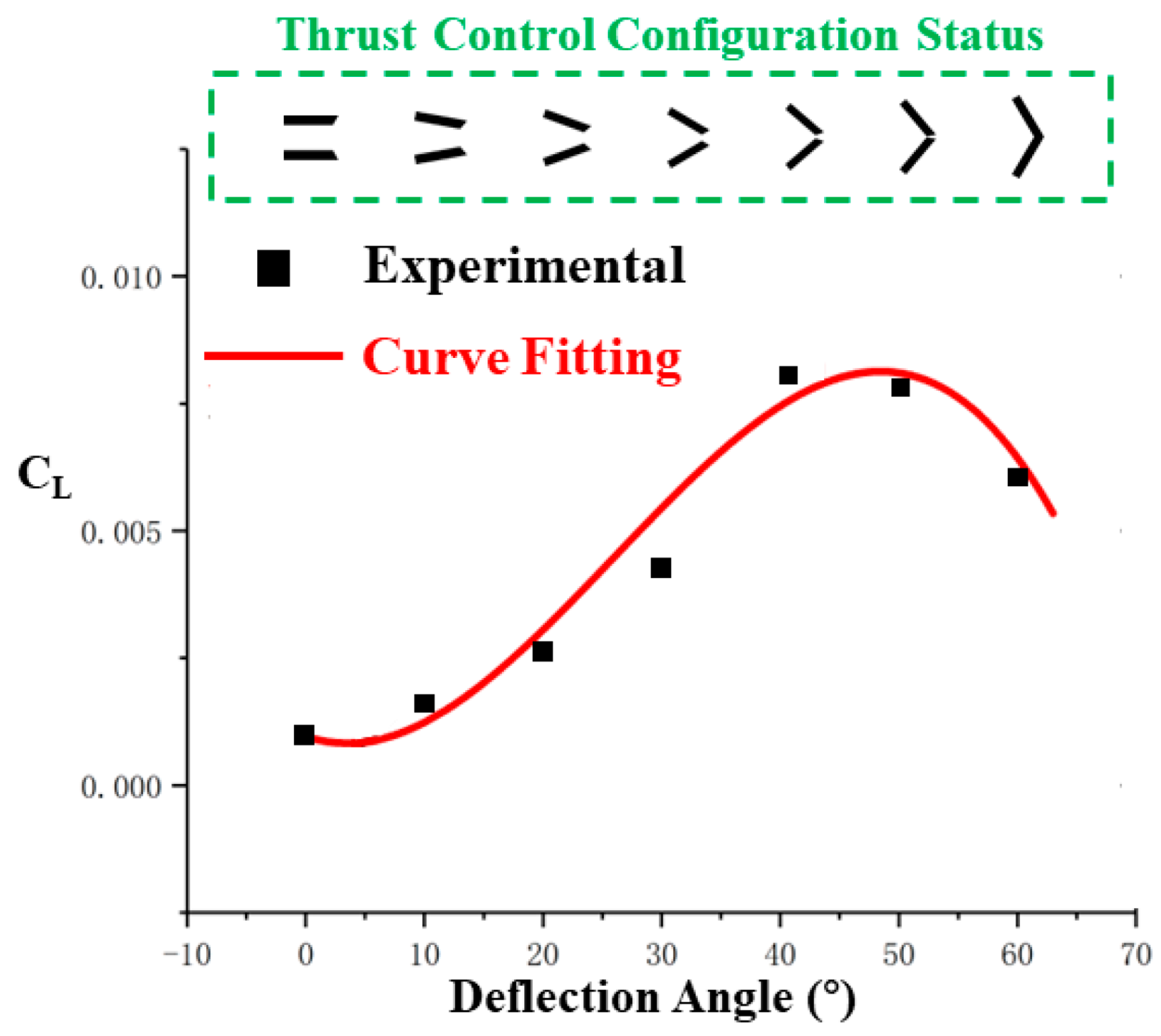
4.1. Symmetrical Deflection of Both Cascades

The impact of the thrust control configuration on the aircraft′s thrust, lift, and pitch moment was measured under different angles of symmetrical deflection of the thrust control plates. The experimental results for the lift coefficient, as depicted in Figure 14, indicate that, during the symmetrical deflection of the thrust control plates, the additional lift coefficient remained above zero and exhibited an increasing trend as a function of the deflection angle. The increase in lift was due to the fact that the symmetrical deflection of the upper and lower cascades effectively formed a contracting flow channel along the direction of the airflow. This contraction caused the airflow to accelerate within the channel, thereby increasing the inlet airflow velocity to the fan. As a result, the additional lift generated by the BLI fans, due to the suction of the boundary-layer air, was enhanced. However, past a 50° deflection angle, there was a noticeable reduction in additional lift due to the airflow separation or stall-like conditions induced by the excessive deflection.
Figure 15 outlines the behavior of the pitch moment with varying deflection angles. Initially, within a deflection range from 0 to 20°, the pitch moment remained minimal, suggesting a balanced aerodynamic force distribution along the aircraft′s center of gravity. As the deflection angle increased beyond this range, the pitch moment increased significantly, reaching a peak when the thrust control plates were fully deflected. This can be explained by the forward shift in the center of pressure due to the deflected plates, creating a larger arm to the center of gravity and, hence, a higher pitch moment.
As shown in Figure 16, the thrust coefficient decreased progressively with an increase in the deflection angle, approaching a minimum when the plates were fully closed. This trend is consistent with the aerodynamic principle that, as the deflection of the control plates increases, the effective exit area for the jet decreases, which, in turn, reduces the jet velocity and the resulting thrust due to the conservation of the mass flow rate through the propulsors.

4.2. Deflection of the Upper Cascades

The impact of the thrust control configuration on the aircraft′s thrust, lift, and pitch moment was measured under different angles of deflection of the upper cascades. As shown in Figure 17, the additional lift coefficient remained positive across the range of deflection angles, implying that, as the upper plate deflected, it contributed to an increase in lift due to the change in the airflow pattern over the control surface. The lift coefficient initially increased with the angle of deflection, showcasing an augmented aerodynamic efficiency. However, this trend reversed beyond a certain deflection point, as evidenced by the descent in the additional lift beyond a 50° angle. This decline corresponds to the aerodynamic limit, whereupon further deflection no longer contributes positively to lift generation, potentially due to flow separation or stall.
In Figure 18, the curve representing the pitch moment illustrates an initial decrease and subsequent increase with an increase in the deflection angle of the upper cascades. In the 0 to 50° range, the aircraft experiences a nose-down pitch moment, while past this deflection threshold, the pitch moment transitions to a nose-up behavior. This phenomenon can be attributed to the changing center of pressure on the upper surface as the deflection angle increased, which initially shifted aft and then forward as the angle progressed beyond 50°.
The variation in thrust with variation in the deflection angle of the upper cascades is shown in Figure 19. As the deflection angle widened, a consistent decrease in thrust was observed, with the thrust coefficient being reduced to approximately 37.5% of its original value at maximum deflection. This diminishing thrust can be rationalized by the increased obstruction to the outflow of the jet stream caused by the deflected plate, which effectively altered the exit geometry and flow dynamics of the propulsion system, resulting in a decrease in thrust.

4.3. Deflection of the Lower Cascades

The impact of the thrust control configuration on the aircraft′s thrust, lift, and pitch moment was measured under different angles of deflection of the lower cascades. As depicted in Figure 20, the additional lift showed a consistently negative trend, meaning that, as the lower plate was deflected, this created a downwash effect that reduced the overall lift produced by the wing. This negative lift intensified with an increase in the deflection angle, indicating a direct relationship between the angle of deflection and the aerodynamic penalty in terms of lift reduction.
Figure 21 indicates that the aircraft exhibited a consistent nose-up pitch moment across all angles of deflection. This increase in the pitch moment indicated that deflecting the lower plate affected the airflow in a manner that increased the lift at the rear of the aircraft relative to the front, thereby pitching the nose upward. The pitch moment increased linearly with the deflection angle, suggesting a proportional effect of deflection on the pitching dynamics.
The thrust produced by the aircraft was inversely related to the deflection angle of the lower plate, as shown in Figure 22. As the angle increased, the effective exhaust area for the propulsion system diminished, leading to a reduction in thrust. The thrust reached a nadir at the maximum deflection, dropping to approximately 27.5% of its initial value, mirroring the obstruction caused by the plate to the outflowing jet stream.

4.4. Deflection Angle Combinations for Zero Pitch Moment

Figure 23 illustrates a combination of the thrust control method where the pitch moment was maintained at zero during the deflection of the upper and lower cascades. In this thrust control configuration, as the upper cascades′ angle of deflection increased, the lower cascades′ angle of deflection initially increased and then decreased to maintain the pitch moment induced by the thrust control configuration at zero.
Figure 24 illustrates the experimental outcomes regarding the influences of deflection angles on the thrust and lifting coefficients under a condition where the pitch moment remained constant. The thrust coefficient, depicted in black, decreased linearly with an increasing deflection angle, demonstrating a reduction to 20% of its initial value at higher angles. In contrast, the lifting coefficient, shown in red, initially remained stable and then exhibited a significant increase, peaking around the middle of the angle range before declining. This behavior indicates that the deflection scheme not only preserved the initial enhancement of lift, but also augmented it further at certain deflection angles. Importantly, these adjustments in the deflection angles reduced the thrust significantly while maintaining a nearly constant pitch moment, thereby optimizing the aerodynamic performance by enhancing lift without compromising stability.

4.5. Comparison of Landing Stability Optimization Methods

Landing stability optimization methods for different aircraft configurations, including traditional tube-and-wing aircraft, aeroengine-powered BWB aircraft, and electric BWB aircraft with novel thrust control configurations, are compared in Table 1. Traditional tube-and-wing aircraft utilize trailing-edge flaps to increase lift and deploy spoilers and engine thrust reversers to decelerate. Aeroengine-powered BWB aircraft employ belly flaps and spoilers to achieve similar effects, but in electric BWB aircraft, where engine thrust reversers cannot be used, a novel thrust control configuration is adopted to reduce speed and maintain lift without decreasing the fan rotation speed. The advantages and disadvantages of each design reveal key differences in their structural complexity, operational ease, stability, and safety. Traditional tube-and-wing aircraft are easier to operate and maintain, while BWB aircraft offer better lift and stability control, but face challenges with flow separation and aerodynamic coupling. Electric BWB aircraft enhance landing safety and controllability with their novel thrust control, but require more complex designs and precise control to avoid instability.

5. Conclusions

In conclusion, this study proposes a novel thrust control configuration to optimize the landing stability of BWB aircraft with distributed electric BLI propulsors. In its passive state, the apparatus acts as a horizontal stabilizer, contributing to the overall stability of the aircraft. Upon its activation during landing, the device not only decelerates the aircraft, but also augments lift, effectively mitigating the issues of settlement and altitude loss. Ground-based testing yielded the following conclusions:
(1)
The novel thrust control configuration can effectively adjust the thrust to 0 without adjusting the BLI fan speed of the propulsion system, improving the landing stability of BWB aircraft and solving the tightly coupled problem between lift and thrust caused by BLI fans sucking in the boundary layer. The challenge in using flaps and engine thrust reversers to decelerate electric BWB aircraft can be overcome.
(2)
The symmetrical deflection of both cascades of the thrust control configuration can increase lift and provide an upward moment. This indicates that the deflection of the thrust control configuration significantly changes the flow field state and can be adjusted to achieve the goal of augmenting lift and reducing drag in landing and approach use scenarios. The additional upward moment provided meets the requirements for larger attitude angles, which can replace the upward movement of elevators and improve aerodynamic efficiency.
(3)
The asymmetric deflection scheme can achieve a zero additional pitch moment with specific deflection angle combinations and effectively adjust the thrust to 20% while maintaining the original additional lift effects and producing some additional lift benefits. This method also achieves the objectives of augmenting lift and reducing drag without inducing additional changes in the pitch moment.

Author Contributions

M.Y. and Z.T. conceived and designed the configuration; M.Y. and P.T. performed the experiments; M.Y. and H.L. analyzed the data; M.Y. wrote the paper. All authors have read and agreed to the published version of the manuscript.

Funding

This research received no external funding.

Institutional Review Board Statement

Not applicable.

Informed Consent Statement

Not applicable.

Data Availability Statement

The original contributions presented in the study are included in the article, further inquiries can be directed to the corresponding author.

Conflicts of Interest

The authors declare no conflicts of interest.

References

  1. Moirou, N.G.M.; Sanders, D.S.; Laskaridis, P. Advancements and Prospects of Boundary Layer Ingestion Propulsion Concepts. Prog. Aerosp. Sci. 2023, 138, 100897. [Google Scholar] [CrossRef]
  2. Bravo-Mosquera, P.D.; Catalano, F.M.; Zingg, D.W. Unconventional Aircraft for Civil Aviation: A Review of Concepts and Design Methodologies. Prog. Aerosp. Sci. 2022, 131, 100813. [Google Scholar] [CrossRef]
  3. Fard, M.T.; He, J.; Huang, H.; Cao, Y. Aircraft Distributed Electric Propulsion Technologies—A Review. IEEE Trans. Transp. Electrific. 2022, 8, 4067–4090. [Google Scholar] [CrossRef]
  4. Chaudhary, S.; Sharma, D. A comprehensive review on blended wing body aircraft. Vidyabharati Int. Interdiscip. Res. J. 2021, 12, 271–278. [Google Scholar]
  5. Sahoo, S.; Zhao, X.; Kyprianidis, K. A Review of Concepts, Benefits, and Challenges for Future Electrical Propulsion-Based Aircraft. Aerospace 2020, 7, 44. [Google Scholar] [CrossRef]
  6. Rendón, M.A.; Sánchez, R.C.D.; Gallo, M.J.; Anzai, A.H. Aircraft Hybrid-Electric Propulsion: Development Trends, Challenges and Opportunities. J. Control Autom. Electr. Syst. 2021, 32, 1244–1268. [Google Scholar] [CrossRef]
  7. Handa, S.; Srinivas, G. Recent Developments of Blended Wing Body Aircraft: Experimental, Numerical and Theoretical Approaches. Aerosp. Syst. 2022, 5, 171–183. [Google Scholar] [CrossRef]
  8. Felder, J.L.; Tong, M.T.; Schnulo, S.L.; Berton, J.J.; Thacker, R.P.; Haller, W.J.; Kirk, J.; Guynn, M.D. Updated Assessment of Turboelectric Boundary Layer Ingestion Propulsion Applied to Single-Aisle Commercial Transport; Glenn Research Center: Cleveland, OH, USA, 2022. [Google Scholar]
  9. Okonkwo, P.; Smith, H. Review of Evolving Trends in Blended Wing Body Aircraft Design. Prog. Aerosp. Sci. 2016, 82, 1–23. [Google Scholar] [CrossRef]
  10. Kim, H.D.; Perry, A.T.; Ansell, P.J. A Review of Distributed Electric Propulsion Concepts for Air Vehicle Technology. In Proceedings of the 2018 AIAA/IEEE Electric Aircraft Technologies Symposium, Cincinnati, OH, USA, 9–11 July 2018; American Institute of Aeronautics and Astronautics: Reston, VA, USA, 2018. [Google Scholar]
  11. Gohardani, A.S.; Doulgeris, G.; Singh, R. Challenges of Future Aircraft Propulsion: A Review of Distributed Propulsion Technology and Its Potential Application for the All Electric Commercial Aircraft. Prog. Aerosp. Sci. 2011, 47, 369–391. [Google Scholar] [CrossRef]
  12. Brown, M.; Vos, R. Conceptual Design and Evaluation of Blended-Wing Body Aircraft. In Proceedings of the 2018 AIAA Aerospace Sciences Meeting, Kissimmee, FL, USA, 8–12 January 2018; American Institute of Aeronautics and Astronautics: Reston, VA, USA, 2018. [Google Scholar]
  13. Niu, X.; Li, J.; Zhang, H.; Yang, Z. Investigation of Improvement Design on Aileron Surface Flow State of High Lift Configuration in BWB. Aerospace 2022, 9, 842. [Google Scholar] [CrossRef]
  14. Ammar, S.; Legros, C.; Trépanier, J.-Y. Conceptual Design, Performance and Stability Analysis of a 200 Passengers Blended Wing Body Aircraft. Aerosp. Sci. Technol. 2017, 71, 325–336. [Google Scholar] [CrossRef]
  15. Yu, G.; Duan, Y. Design Improvement of a BWB Aerodynamic Performance at Cruise and Take-Off Speeds. Int. J. Aerosp. Eng. 2022, 2022, 5216387. [Google Scholar] [CrossRef]
  16. Kleemann, N.; Karpuk, S.; Elham, A. Conceptual Design and Optimization of a Solar-Electric Blended Wing Body Aircraft for General Aviation. In Proceedings of the AIAA Scitech 2020 Forum, Orlando, FL, USA, 6–10 January 2020; American Institute of Aeronautics and Astronautics: Reston, VA, USA, 2020. [Google Scholar]
  17. Wang, K.; Zhou, Z. Aerodynamic Design, Analysis and Validation of a Small Blended-Wing-Body Unmanned Aerial Vehicle. Aerospace 2022, 9, 36. [Google Scholar] [CrossRef]
  18. Mv, M.; Mondal, P.; Karn, P.K.; Kumar, P. Aerodynamic Investigation of Blended Wing Body Configuration. Def. Sci. J. 2023, 73, 283–292. [Google Scholar] [CrossRef]
  19. Hossan, S.; Srinivas, G. Aerodynamic Performance Improvement of a Blended Wing-Body Re-Entry Vehicle Using ANSYS CFX. Aerosp. Syst. 2023, 7, 29–42. [Google Scholar] [CrossRef]
  20. Agarwal, D.; Marques, S.; Robinson, T.T. Aerodynamic Shape Optimisation Using Parametric CAD and Discrete Adjoint. Aerospace 2022, 9, 743. [Google Scholar] [CrossRef]
  21. Kerho, M.F. Aero-Propulsive Coupling of an Embedded, Distributed Propulsion System. In Proceedings of the 33rd AIAA Applied Aerodynamics Conference, Dallas, TX, USA, 22–26 June 2015; American Institute of Aeronautics and Astronautics: Reston, VA, USA, 2015. [Google Scholar]
  22. Urban, D.; Kusmirek, S.; Socha, V.; Hanakova, L.; Hylmar, K.; Kraus, J. Effect of Electric Ducted Fans Structural Arrangement on Their Performance Characteristics. Appl. Sci. 2023, 13, 2787. [Google Scholar] [CrossRef]
  23. Zhao, W.; Zhang, Y.; Wu, J. Energy-Based Aerodynamic Analysis on the Blended-Wing-Body Aircraft with Boundary Layer Ingestion. Int. J. Aerosp. Eng. 2022, 2022, 6452099. [Google Scholar] [CrossRef]
  24. Giuliani, J.E.; Chen, J.P.; Beach, T.A.; Bakhle, M.A. Numerical Simulation of Boundary Layer Ingesting (BLI) Inlet/Fan Interaction. In Proceedings of the 50th AIAA/ASME/SAE/ASEE Joint Propulsion Conference, Cleveland, OH, USA, 28–30 July 2014; American Institute of Aeronautics and Astronautics: Reston, VA, USA, 2014. [Google Scholar]
  25. Jia, Y.; Li, J.; Wu, J. Power Fan Design of Blended-Wing-Body Aircraft with Distributed Propulsion System. Int. J. Aerosp. Eng. 2021, 2021, 5128136. [Google Scholar] [CrossRef]
  26. Seitz, A.; Habermann, A.L.; Peter, F.; Troeltsch, F.; Castillo Pardo, A.; Della Corte, B.; Van Sluis, M.; Goraj, Z.; Kowalski, M.; Zhao, X.; et al. Proof of Concept Study for Fuselage Boundary Layer Ingesting Propulsion. Aerospace 2021, 8, 16. [Google Scholar] [CrossRef]
  27. Diamantidou, D.E.; Hosain, M.L.; Kyprianidis, K.G. Recent Advances in Boundary Layer Ingestion Technology of Evolving Powertrain Systems. Sustainability 2022, 14, 1731. [Google Scholar] [CrossRef]
  28. Yu, G.; Li, D.; Zhang, Z. Numerical Simulation for the Differences between FTN/WPN Engine Models Aerodynamic Influence on BWB300 Airframe. Eng. Appl. Comput. Fluid Mech. 2020, 14, 566–579. [Google Scholar] [CrossRef]
  29. Wu, J.; Gao, F.; Li, S.; Yang, F. Conceptual Design and Optimization of Distributed Electric Propulsion General Aviation Aircraft. Aerospace 2023, 10, 387. [Google Scholar] [CrossRef]
  30. Hospodář, P.; Klesa, J.; Žižkovský, N. Design of Distributed Propulsion System for General Aviation Airplane. MATEC Web Conf. 2019, 304, 03009. [Google Scholar] [CrossRef]
  31. Burston, M.; Ranasinghe, K.; Gardi, A.; Parezanović, V.; Ajaj, R.; Sabatini, R. Design Principles and Digital Control of Advanced Distributed Propulsion Systems. Energy 2022, 241, 122788. [Google Scholar] [CrossRef]
  32. Zhang, X.; Zhang, W.; Li, W.; Zhang, X.; Lei, T. Experimental Research on Aero-Propulsion Coupling Characteristics of a Distributed Electric Propulsion Aircraft. Chin. J. Aeronaut. 2023, 36, 201–212. [Google Scholar] [CrossRef]
  33. Wick, A.T.; Hooker, J.R.; Zeune, C.H. Integrated Aerodynamic Benefits of Distributed Propulsion. In Proceedings of the 53rd AIAA Aerospace Sciences Meeting, Kissimmee, FL, USA, 5–9 January 2015; American Institute of Aeronautics and Astronautics: Reston, VA, USA, 2015. [Google Scholar]
  34. Zhao, W.; Zhang, Y.; Tang, P.; Wu, J. The Impact of Distributed Propulsion on the Aerodynamic Characteristics of a Blended-Wing-Body Aircraft. Aerospace 2022, 9, 704. [Google Scholar] [CrossRef]
  35. Reist, T.A.; Zingg, D.W.; Rakowitz, M.; Potter, G.; Banerjee, S. Multifidelity Optimization of Hybrid Wing–Body Aircraft with Stability and Control Requirements. J. Aircr. 2019, 56, 442–456. [Google Scholar] [CrossRef]
  36. Chang, M.; Zheng, Z.; Meng, X.; Bai, J.; Wang, B. Aerodynamic Analysis of a Low-Speed Tandem-Channel Wing for eVTOL Aircraft Considering Propeller–Wing Interaction. Energies 2022, 15, 8616. [Google Scholar] [CrossRef]
  37. Vechtel, D.; Buch, J.-P. Aspects of Yaw Control Design of an Aircraft with Distributed Electric Propulsion. CEAS Aeronaut. J. 2022, 13, 847–860. [Google Scholar] [CrossRef]
  38. Chen, Z.; Zhang, M.; Chen, Y.; Sang, W.; Tan, Z.; Li, D.; Zhang, B. Assessment on Critical Technologies for Conceptual Design of Blended-Wing-Body Civil Aircraft. Chin. J. Aeronaut. 2019, 32, 1797–1827. [Google Scholar] [CrossRef]
  39. Paulus, D.; Wirth, C.; Hornung, M. Blended Wing Body Aircraft—Recommendations from High Lift and Control Surface Design and Optimization. In Proceedings of the 31st AIAA Applied Aerodynamics Conference, San Diego, CA, USA, 24–27 June 2013; American Institute of Aeronautics and Astronautics: Reston, VA, USA, 2013. [Google Scholar]
  40. Sargeant, M.A.; Hynes, T.P.; Graham, W.R.; Hileman, J.I.; Drela, M.; Spakovszky, Z.S. Stability of Hybrid-Wing-Body-Type Aircraft with Centerbody Leading-Edge Carving. J. Aircr. 2010, 47, 970–974. [Google Scholar] [CrossRef]
  41. Lou, Y.; Chen, Z.; Jiang, S. Numerical Simulation on Influence of Thrust Reverser Device on Aerodynamic Performance of Blended-Wing-Body Distributed Propulsion System. J. Aerosp. Power 2019, 34, 2211–2217. [Google Scholar]
  42. Ye, Z.; Chen, Y.; Cai, P.; Lyu, H.; Gong, Z.; Wu, J. Control Design for Soft Transition for Landing Preparation of Light Compound-Wing Unmanned Aerial Vehicles Based on Incremental Nonlinear Dynamic Inversion. Appl. Sci. 2023, 13, 12225. [Google Scholar] [CrossRef]
  43. Lu, Y.; Zhang, S.; Li, X. A Hazard Analysis-Based Approach to Improve the Landing Safety of a BWB Remotely Piloted Vehicle. Chin. J. Aeronaut. 2012, 25, 846–853. [Google Scholar] [CrossRef]
  44. Staelens, Y.; Blackwelder, R.; Page, M. Study of Belly-Flaps to Enhance Lift- and Pitching Moment Coefficient of a BWB-Airplane. In Proceedings of the 25th AIAA Applied Aerodynamics Conference, Miami, FL, USA, 25–28 June 2007; American Institute of Aeronautics and Astronautics: Reston, VA, USA, 2007. [Google Scholar]
  45. Xin, Z.; Chen, Z.; Gu, W.; Zhang, M.; Zhang, B. Externally Blown Elevon Applied for the Longitudinal Control of Blended Wing Body Transport with Podded Engines. Aerosp. Sci. Technol. 2019, 93, 105324. [Google Scholar] [CrossRef]
  46. Viviani, A.; Aprovitola, A.; Iuspa, L.; Pezzella, G. Low Speed Longitudinal Aerodynamics of a Blended Wing-Body Re-Entry Vehicle. Aerosp. Sci. Technol. 2020, 107, 106303. [Google Scholar] [CrossRef]
  47. Chung, J.; Hallberg, E.; Cox, S.; Plyler, M. Landing Pitch Control Analysis of a Blended Wing Body UCAV. In Proceedings of the 48th AIAA Aerospace Sciences Meeting Including the New Horizons Forum and Aerospace Exposition, Orlando, FL, USA, 4–7 January 2010; American Institute of Aeronautics and Astronautics: Reston, VA, USA, 2010. [Google Scholar]
  48. Zhou, S.; Zhou, Y.; Xu, Z.; Chang, W.; Cheng, Y. The Landing Safety Prediction Model by Integrating Pattern Recognition and Markov Chain with Flight Data. Neural Comput. Appl. 2019, 31, 147–159. [Google Scholar] [CrossRef]
  49. Gang, Y.; Dong, L.; Zhenli, C.; Zeyu, Z. Blended Wing Body Thrust Reverser Cascade Feasibility Evaluation Through CFD. IEEE Access 2019, 7, 155184–155193. [Google Scholar] [CrossRef]
  50. Zhao, J.; Wang, X.; Meng, C.; Song, H.; Luo, Z.; Han, Q. Dynamic Modeling and Analysis of Thrust Reverser Mechanism Considering Clearance Joints and Flexible Component. Aerospace 2022, 9, 611. [Google Scholar] [CrossRef]
  51. Staelens, Y.; Blackwelder, R.; Page, M. Novel Pitch Control Effectors for a Blended Wing Body Airplane in Takeoff and Landing Configuration. In Proceedings of the 45th AIAA Aerospace Sciences Meeting and Exhibit, Reno, NV, USA, 8–11 January 2007; American Institute of Aeronautics and Astronautics: Reston, VA, USA, 2007. [Google Scholar]
  52. Anderson, J.D. Fundamentals of Aerodynamics, 6th ed.; McGraw-Hill Education: New York, NY, USA, 2017. [Google Scholar]
  53. Feng, Y.; Tang, J.; He, Z.; Xue, X.; Dong, M. Design of flap/spoiler follower mechanism for civil aircraft. J. Phys. Conf. Ser. 2023, 2472, 012016. [Google Scholar] [CrossRef]
  54. Tsirkunov, Y.M.; Lobanova, M.A.; Tsvetkov, A.I.; Schepanyuk, B.A. Effect of the wing trailing-edge flaps and spoilers position on the jet-vortex wake behind an aircraft during takeoff and landing run. In Proceedings of the 7th European Conference for Aeronautics and Space Sciences (EUCASS), Milan, Italy, 3–6 July 2017. [Google Scholar] [CrossRef]
  55. Hileman, J.; Spakovszky, Z.; Drela, M.; Sargeant, M.; Jones, A. Airframe design for silent fuel-efficient aircraft. J. Aircr. 2010, 47, 956–969. [Google Scholar] [CrossRef]
  56. Wildschek, A. Flight dynamics and control related challenges for design of a commercial blended wing body aircraft. In Proceedings of the AIAA Guidance, Navigation, and Control Conference, National Harbor, MD, USA, 13–17 January 2014; AIAA: Reston, VA, USA, 2014. [Google Scholar]
Figure 1. Sagging problem of BWB aircraft caused by short lever arms.
Applsci 14 08546 g001
Figure 2. Schematic of BWB aircraft with distributed electric BLI propulsors.
Applsci 14 08546 g002
Figure 3. Schematic diagram of a dual-layer sleeve thrust control configuration: (a) normal thrust and (b) reverse thrust.
Applsci 14 08546 g003
Figure 4. Components and motion of a dual-layer sleeve thrust control configuration.
Applsci 14 08546 g004
Figure 5. Schematic diagram of a separate flap-type thrust control configuration.
Applsci 14 08546 g005
Figure 6. Components and motion of a separate flap-type thrust control configuration: (a) normal thrust and (b) reverse thrust.
Applsci 14 08546 g006
Figure 7. Schematic diagram of a single-stage linkage flap-type thrust control configuration.
Applsci 14 08546 g007
Figure 8. Components and motion of a single-stage linkage flap-type thrust control configuration.
Applsci 14 08546 g008
Figure 9. Schematic diagram of a dual-stage linkage flap-type thrust control configuration.
Applsci 14 08546 g009
Figure 10. Components and motion of a dual-stage linkage flap-type thrust control configuration.
Applsci 14 08546 g010
Figure 11. Schematic diagram of BWB aircraft with novel thrust control configuration.
Applsci 14 08546 g011
Figure 12. Force model of BWB aircraft.
Applsci 14 08546 g012
Figure 13. Schematic diagram of the experimental setup for BWB aircraft with novel thrust control configuration.
Applsci 14 08546 g013
Figure 14. CL variation with deflection angles in symmetrical cascade deflection.
Applsci 14 08546 g014
Figure 15. CM variation with deflection angles in symmetrical cascade deflection.
Applsci 14 08546 g015
Figure 16. T variation with deflection angles in symmetrical cascade deflection.
Applsci 14 08546 g016
Figure 17. CL variation with deflection angles in upper cascade deflection.
Applsci 14 08546 g017
Figure 18. CM variation with deflection angles in upper cascade deflection.
Applsci 14 08546 g018
Figure 19. T variation with deflection angles in upper cascade deflection.
Applsci 14 08546 g019
Figure 20. CL variation with deflection angles in lower cascade deflection.
Applsci 14 08546 g020
Figure 21. CM variation with deflection angles in lower cascade deflection.
Applsci 14 08546 g021
Figure 22. T variation with deflection angles in lower cascade deflection.
Applsci 14 08546 g022
Figure 23. Deflection angle combinations for zero pitch moment (CM = 0) in both cascades.
Applsci 14 08546 g023
Figure 24. Variation in CL and T with deflection angles under constant-pitch-moment conditions.
Applsci 14 08546 g024
Table 1. Comparison of landing stability optimization methods for different aircraft configurations.
To Maintain Lift and Reduce Speed During LandingTraditional Tube-and-Wing Aircraft [53,54]Aeroengine-Powered BWB Aircraft [51,55,56]Electric BWB Aircraft with Novel Thrust Control Configuration
Methods1. Trailing-edge flaps used to increase lift.
2. Spoilers and engine thrust reversers used to slow down.
1. Belly flaps used to increase lift.
2. Spoilers and engine thrust reversers used to slow down.
1. Novel thrust control configuration behind BLI fans used to reduce speed and maintain lift without decreasing fan rotation speed.
Advantages1. Simple structure, easy to operate and maintain.
2. Mature design suitable for various applications.
1. Greater lift augmentation due to central belly flaps.
2. Reduced interference with roll and pitch control, enhancing stability.
1. Enhanced landing safety and controllability with thrust control configuration.
2. Without additional pitch moments.
3. Suitable for electric BWB without a fuel engine.
Disadvantages1. Difficult to use flaps and spoilers in BWB designs due to aerodynamic coupling between wings and fuselage.1. Belly flaps may cause flow separation.
2. Impossible to use engine thrust reversers in electric BWB aircraft.
1. Complex structure increases the difficulty in design and maintenance.
2. Requires precise control to avoid instability.
Disclaimer/Publisher’s Note: The statements, opinions and data contained in all publications are solely those of the individual author(s) and contributor(s) and not of MDPI and/or the editor(s). MDPI and/or the editor(s) disclaim responsibility for any injury to people or property resulting from any ideas, methods, instructions or products referred to in the content.

