Abstract
The methods of increasing the efficiency of internal combustion engines through heat utilization are examined. A proposed classification of heat utilization systems for mobile energy vehicles is presented. External utilization harnesses the heat generated by a diesel engine to fulfill the needs of consumers not directly related to the engine, such as interior heating and air conditioning systems. Internal recycling focuses on enhancing the power, environmental performance, and economic performance of an engine and its related systems. Various heat utilization schemes are compared. For the economic conditions of the European Union (EU), a turbocompounding diesel engine is acceptable if its agricultural tractor rated power is more than 275 kW and its combine harvester rated power is more than 310 kW. Steam injection into the combustion chamber is utilized to improve the technical and economic performance of gas turbine engines. This technology is also produced in Ukraine and is proposed for use in internal combustion engines. It is suggested to inject water vapor into a turbocharger turbine. This approach reduces the number of components in the heat recovery system, thereby lowering its cost. A recycling chiller can be employed to cool the air after it passes through the air cleaner, enhance the efficiency of the air cooler, and improve the performance of the thermoelectric generators. This device is particularly effective at relatively high air temperatures and can be recommended for agricultural machinery that operates in such conditions, such as combines. With the application of this new technology, it is possible to increase the power of diesel engines by 15…20% and reduce fuel consumption by up to 14%. Further research will focus on substantiating the parameters of recycling systems for different classes of vehicles. Developing a methodology to justify the effective application of heat utilization systems in agricultural mobile energy vehicles is advisable.
1. Introduction
Modern agricultural machinery is equipped with thermal piston engines of internal combustion, which use engines with relatively low efficiency: diesel engines reach up to 42…44%; gasoline engines reach up to 27%. Thus, exhaust gases, the heat of the cooling system, lubrication, and air cooling result in energy equivalent to approximately 875,000 tons of diesel fuel and 292,000 tons of gasoline being lost annually [1].
At least 50% of the heat of fuel combustion is lost to exhaust gases and coolant. Therefore, there are significant reserves for improving the efficiency of diesel power plants. Work to reduce these heat losses has been carried out in two main directions: the creation of engines with a higher values of efficiency and the development of heat recovery systems for existing engines. The latter direction does not require the radical modernization of the engine [2].
A number of leading machine-building companies (Scania, Ford, BMW, Cummins, Navistar Advanced Technology, etc.) and scientific centers of universities are dealing with issues of heat utilization in mobile energy vehicles. For instance, specialists at the Navistar Advanced Technology company consider the use of heat recovery systems to be one of the main components of achieving their ambitious goal of 50% diesel efficiency [3].
The diesel engines of agricultural machinery have their own characteristic features during operation that significantly distinguish them from other vehicles. For instance, the engines of tractors and combines are used at load factors of 60…90%, while most trucks and passenger cars operate at 17%. When performing technological operations, the engine of an agricultural power tool works at a constant frequency of the rotation of the crankshaft.
Today, disposal systems are developed mainly for trucks equipped with powerful engines. Thus, at the present time, there are no proven circuit solutions and equipment that could be used in agricultural machinery for efficient heat utilization. The theoretical aspects of the specified direction of increasing efficiency have been insufficiently worked out. In addition, there is no classification of recycling systems, which complicates the general idea and analysis of this direction of increasing efficiency [4].
The purpose of this work is to analyze and classify heat utilization systems and to determine promising areas of application in mobile energy vehicles for agricultural purposes.
2. Presentation of the Main Material
2.1. Research Methodology
This study utilized several technical and economic indicators. The technical indicators included the exhaust gas energy utilization factor (), the coolant energy utilization factor (), and the specific power of the heat recovery device. The economic indicators comprised return, investment, and the simple payback period.
The exhaust gas energy utilization factor is calculated as follows:
where is the exhaust gas temperature, K, is the ambient temperature, K, and is the exhaust gas temperature after passing through the heat recovery system, K.
The coolant energy from an engine can be applied for heating purposes, such as space heating or fuel preheating. The coolant energy utilization factor is determined by the following:
where is the coolant temperature at the engine outlet, K, is the coolant temperature at the engine inlet, K, and is the coolant temperature at the outlet of the waste heat recovery exchanger, K.
The exhaust gas temperature must exceed the dew point temperature of sulfuric acid vapors. The minimum permissible exhaust gas outlet temperature is calculated by the formula:
where is the steam dew point temperature, K, is the sulfur content in diesel fuel (%), and is a temperature margin set at 25 K.
We propose using the total waste heat utilization factor to evaluate the energy efficiency of a heat recovery system. This factor represents the ratio of the system’s power to the total input energy from fuel, calculated as:
where is the power of the waste heat recovery unit, kW, is the efficiency of the diesel engine, and is the rated power of the engine, kW.
The capacity of the waste heat absorption chiller can be calculated using the formula:
where is the power coefficient, is the exhaust gas mass flow rate, kg/s, and is the specific heat capacity of the exhaust gases, kJ/(kg·K).
Standard methods were used to evaluate engine efficiency at different intake temperatures. An economic analysis was performed by calculating the simple payback period and determining the maximum acceptable investment cost.
2.2. Research Results
There are two main schemes for the utilization of secondary energy resources: conventional and deep. For a long time, they have been developed mainly for ships and stationary power plants.
The system of deep heat utilization (SDHU) provides consumers only with thermal energy. The system of deep utilization of heat (SDUH) is designed to provide consumers with thermal and mechanical/electrical energy. Water or liquids with a low boiling point (e.g., refrigerants) can be used as the working fluid [5].
The advantage of SDUH is its more efficient use of heat; its disadvantage is the complexity of the design, high initial cost and high operating cost. It is also more sensitive to changes in engine operating mode [6,7].
The following methods of heat utilization are widely used today. In energy systems of mobile energy vehicles with frequent stops, especially cars, the efficiency of recycling systems can be increased by using heat accumulators. This can significantly reduce fuel consumption for engine heating, especially in the winter [8,9,10,11]. The most common schemes that allow only partial utilization of spent thermal energy are cabin heating and fuel heating (when using gaseous fuel or highly viscous components).
More complex engineering solutions are also used. For example, engineer Bruce Krauer proposed a six-stroke engine for heat recovery. He used water injection into the engine cylinders after the fourth stroke. The water is supplied at a pressure of up to 15 MPa, which evaporates and performs the working stroke. This allows the power of the engine to be increased by up to 40%, which leads to improvements in its economic and environmental indicators [12].
For a long time (since the 1980s), recycling thermoelectric generators (TEG) were considered promising. However, their widespread implementation is restrained by their relatively low efficiency (10–15%). The generated electrical energy produced can be used to power on-board electrical systems, traction electric motors, fuel heating, etc. Thus, electric fuel heaters have a power of up to 0.28 kW [13]. Today, several projects of TEG integration in cars are being implemented. These include the Ford Fusion 3.0-V 6, BMW X6, Chevrolet Suburban, Renault Trucks, etc. Standard-sized series of TEGs are being developed, which differ in power for different types of cars: for diesel passenger cars—200…300 W; for gasoline passenger cars—500 W; for trucks—1000 W. It is expected that the specific price of TEG will be at the level of 0.3…1.3 USD/W [14,15,16,17].
The current specific cost of TEG stands at approximately EUR 8.4 per watt. The acceptable range of specific costs has been estimated to be from EUR 0.5 per watt for gasoline vehicles to EUR 3 per watt for standard diesel taxis. Some research institutions are striving to develop low-cost modules with the goal of reaching USD 1 per watt. Consequently, TEGs are not currently a financially viable option for agricultural machinery (Figure 1).
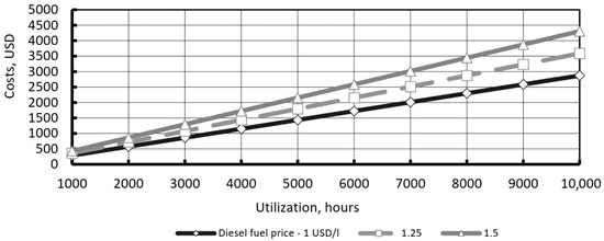
Figure 1.
Fuel cost reduction from thermoelectric generators (TEG), USD/kW. Source: developed by authors.
The idea of injecting hot water is promising. For example, Alfa Power Systems B.V. (Bakersfield, CA, USA) has developed SwirlFlash technology. SwirlFlash is a combustion technology mainly used in gas turbines to improve fuel efficiency and reduce emissions. It involves the use of a swirl mixer combined with a flash vaporization process, where liquid fuel is mixed with superheated steam before being injected into the combustor. This process improves fuel atomization and mixing, resulting in more efficient combustion with lower levels of nitrogen oxides (NOx) and other pollutants. SwirlFlash technology is particularly beneficial in applications where fuel flexibility and low emissions are critical, such as in engines. The improved mixing and vaporization provide a more complete burn, resulting in achieving higher thermal efficiency and lower environmental impact compared to conventional combustion methods. Its principle is simple and effective. Water at a temperature of 150 to 250 °C is injected under a pressure of 10 to 15 MPa into the air flow upstream of the turbocompressor. It evaporates and cools the circulating air [18].
Tests on a 400 kW rated diesel engine showed the following. At a water consumption of 14 g/s (50.4 kg/h), the NOx emission was reduced by 30% without any noticeable decrease in specific fuel consumption. The above scheme makes it possible to dispense with the inflatable air cooler without changing the parameters of the working process. Coolant and exhaust gases can be used to heat water [19].
Booster (power) turbines, as part of the so-called turbocompound system, are being developed by a number of leading companies. The turbocompound system is a technology used in internal combustion engines, particularly diesel engines, to improve fuel efficiency and increase power output. This system captures some of the energy that would otherwise be lost in the exhaust gases and converts it into additional mechanical power. They may be mechanical or electrical. Volvo [20], Iveco, Caterpillar, Cummins, Scania, Detroit Diesel, etc., are working in this direction. The use of mechanical turbocompound systems has resulted in a reduction in specific fuel consumption (% by company): Caterpillar—4.7 [21,22] at nominal power mode; Cummins—6 [23]; Scania—5 [24]. The minimum rated power of the engines equipped with a mechanical turbocompound system is Scania’s DSC 1121 diesel (rated power—235 kW; specific fuel consumption—195 g/(kWh); rated crankshaft speed—1800 rpm).
Similar work has been carried out on the domestic diesel engine SMD-31 (6XH12/14) (Kharkiv Tractor Plant, Kharkov, Ukraine). Using the TS-12.5 power turbine, it is possible to increase power by 10% and reduce fuel consumption by 3.5% (or 8 g/(kWh) [25].
The main drawback of turbocompounding equipment is its relatively high cost, mainly due to the specialized hydromechanical transmission. Therefore, the use of a power turbine to drive the fan of a diesel engine cooling system is of practical interest. The fan consumes up to 7% of the effective power of the diesel engine, which is comparable to the power produced by the power turbine. For a diesel engine with a rated power of 397 kW, it has been found that the use of a turbofan can reduce specific fuel consumption by 5.9% at rated power and by 1.5% at a 45% load factor [26].
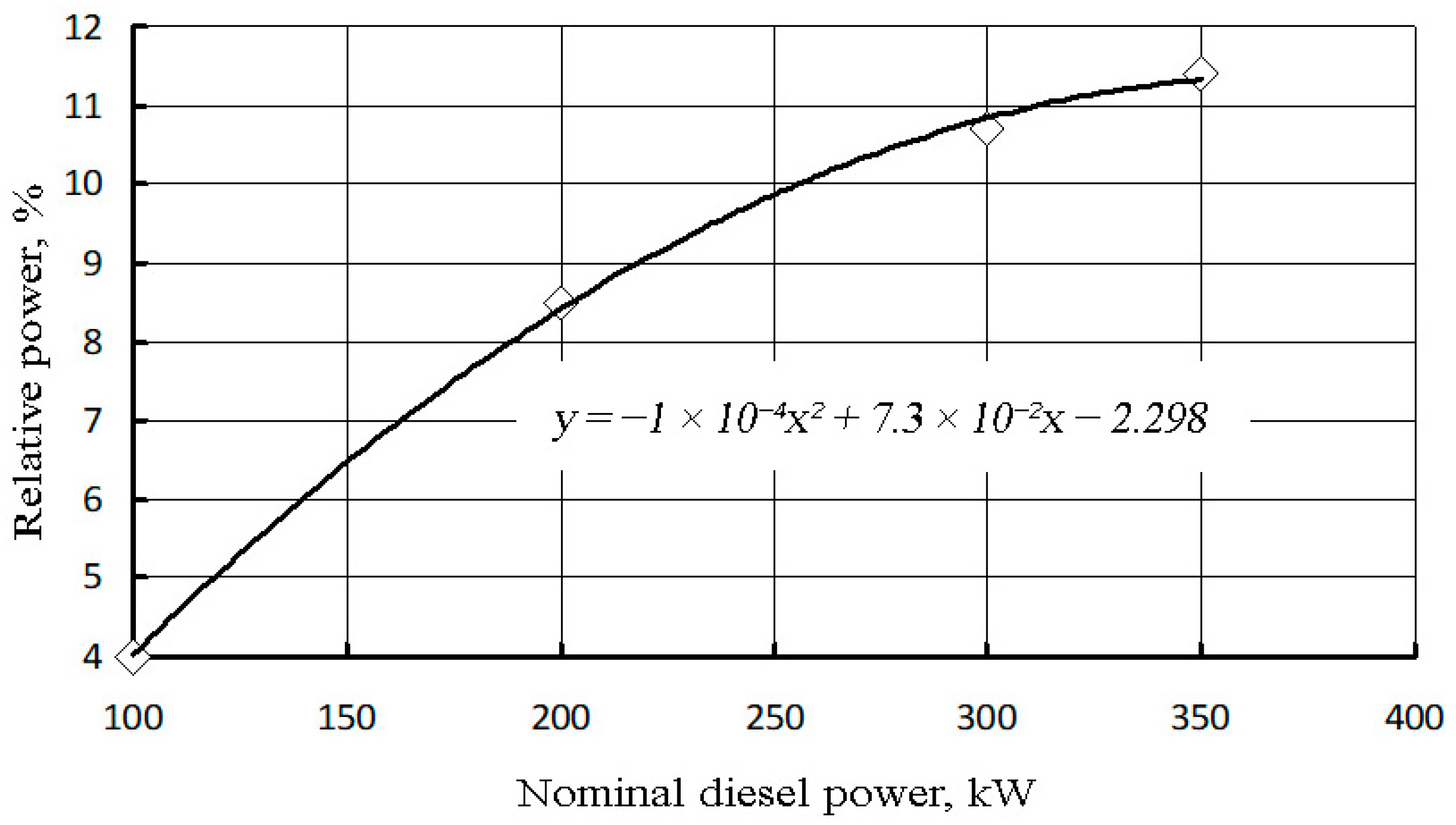
The power of the power turbine depends on the rated power of the diesel engine. Its relative value is built on the basis of experimental data of the company Caterpillar Inc. (Irving, TX, USA), which is shown in Figure 2 [27]. As it can be seen, this dependence is not linear. It can be used for the initial determination of power turbine power.
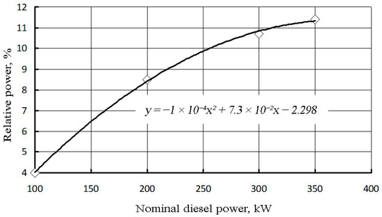
Figure 2.
Relative power of the power turbine as a function of the rated power of the diesel engine.
The main disadvantage of turbocompound power plants is the high complexity and cost of a required special hydromechanical transmission. In this regard, the use of a power turbine to drive such an energy-intensive unit as a fan of a diesel liquid cooling system of a powerful mobile energy vehicle is of practical interest. The possibility of such a solution is confirmed by the fact that at the rated power of a diesel engine with compressed air cooling, about 7% of the effective power of the engine is used to drive of the fan of the liquid cooling system. This is quite close to the power in turbines of turbocompound power plants. Obviously, in this case, the use of a special hydromechanical transmission is not required [28,29,30,31].
Modeling the characteristics of a diesel engine with a 12XH13/14-type engine with a rated power of 397 kW, it was found that the use of a turbofan for the engine liquid cooling system can reduce the specific fuel consumption at the power from 45% to a nominal level by 1.5% and 5.9%, respectively, comparable with a turbodiesel without a power turbine. In the range of engine power from idle to 45%, it is advisable to use an auxiliary electric fan drive (with a power of about 0.8 kW) with a periodic mode of operation [32].
Consider a possible application of diesel engines with a power turbine in agricultural machinery. It is obvious that the turbocompound system is inefficient when using engines with rated power not exceeding 100 kW (Figure 2). The maximum rated power of diesel tractors of the CIS countries is, in kW, as follows: KhTA-300—183.8; Belarus-3022DV—222; K-710S—236; K-704-4R—294. Thus, at the present stage of technical development, it is advisable to use turbocompound engines on general-purpose wheeled tractors with a traction class of at least 5.
With regard to combine harvesters, the following should be noted. Combines with a harvesting capacity of up to 10…11 kg/s have a rated diesel power of up to 200 kW. For example, the power of the engines of combine harvesters with the indicated harvesting capacity is, in kW, as follows: “Skif-230”—169; “Skif-250”—184; Vector-410—154; DON-680—213; GS-812-16—176. More productive machines are also equipped with more powerful engines, as follows, in kW: ACROS-580—221; TORUM-740—294; GS-12—243, etc. It is recommended to use turbocompound engines [33,34,35,36,37].
The Caterpillar company has developed the concept of an electric turbocompound system (Figure 3). Its implementation is expected to reduce specific fuel consumption by 5…10% [38].
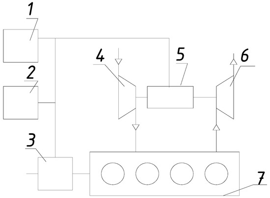
Figure 3.
Electric turbocompound system: 1—electrical load; 2—storage battery; 3—electric motor/generator; 4—compressor; 5—electric generator/engine; 6—turbine; 7—piston engine.
Let us evaluate the effectiveness of waste heat recovery systems. The simple payback period (SPP) is influenced by both investment cost and revenue and is calculated as follows:
where is the return in USD per year, IR is the investment cost in USD, and refers to the annual operating cost in USD.
For turbocompound diesel engines, the investment costs range from USD 2000 to 3400 [22], while for the organic Rankine cycle systems, the costs range from EUR 2000 to 3000 [31], with annual operating costs of EUR 100 for the latter.
The return () is calculated using the following formula:
where is the reduction in specific fuel consumption, kg/kWh, is the rated engine power, kW, is the engine load factor, is the price of diesel fuel (USD/L), and is the density of diesel fuel, kg/L.
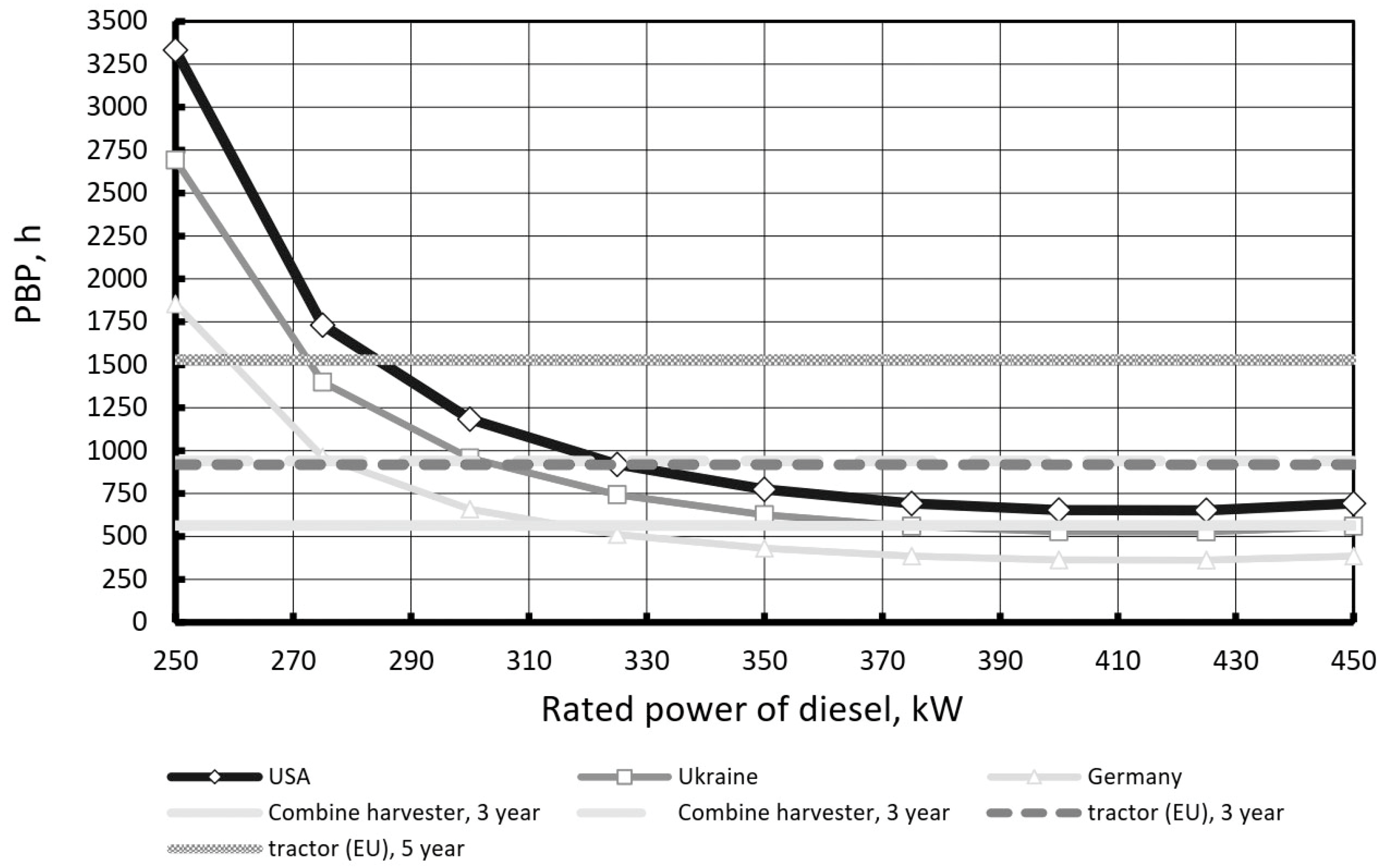
Currently, the rated power of truck engines with turbocompounding ranges from 265 to 460 kW [32,33,34,35]. The simple payback period was calculated based on diesel fuel for the U.S., Germany, and Ukraine, which were USD 0.84, 1.51, and 1.04 per liter, respectively [36]. The calculations show that for engines with a rated power above 370 kW, the payback period remains relatively stable and is less than 750 h. Within this power range, fuel prices have a minimal impact on the payback period. However, for engines with a power rating below 300 kW, fuel prices play a more significant role (Figure 4).
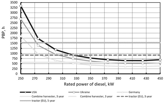
Figure 4.
Simple payback period (PBP) for turbocompound system. Source: developed by authors.
If the relative power output of turbocompound systems varies between 4% and 11.5% (Figure 5), and the diesel engine efficiency is 0.4, the total waste heat utilization factor ranges from 0.0267 to 0.0767, while the exhaust gas energy utilization factor is 0.171 (at = 873 K, = 288 K, and = 773 K).

Figure 5.
Maximum rated power (diesel fuel price—USD/L). Source: developed by authors.
Companies are increasingly adopting energy-saving technologies, and a longer payback period is becoming more acceptable. In the USA, 56% of respondents reported a maximum payback period of three years or less. In Europe, 70% of companies are considering a payback period of up to five years or less [37].
The estimated lifetime of agricultural tractors is about 10,000 h [38], while that of combine harvesters it is approximately 3000 h [39]. In the European Union, the average annual use for a combine harvester is 188 h [40], and for agricultural tractors with a rated power of over 202 kW, it is around 306 h [12]. Outside the EU, the average annual use of tractors is higher. In India, for example, the average annual use of tractors is 856 h [13].
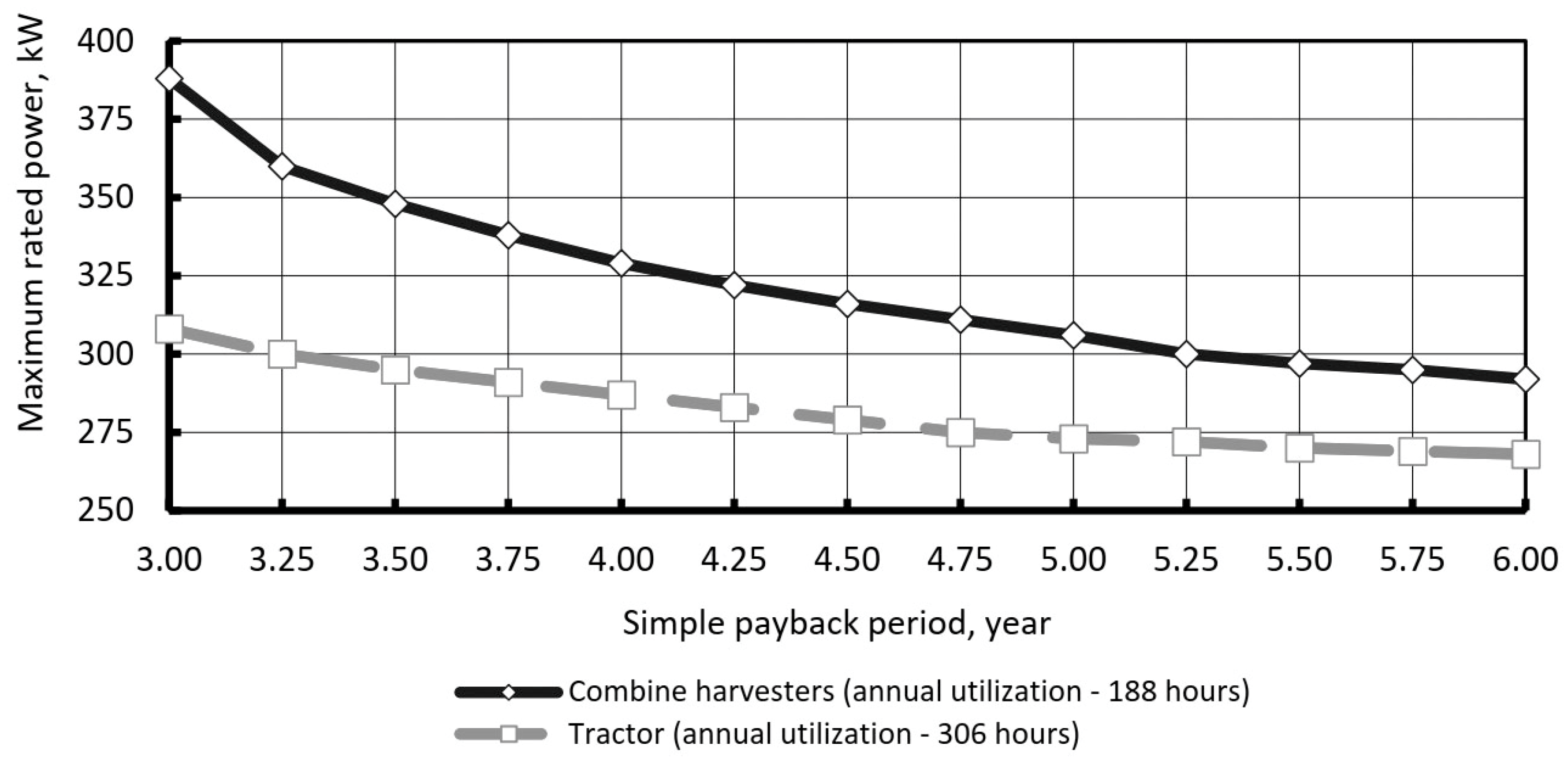
For combine harvesters, turbocompounding can be cost-effective if the rated power is above 300–320 kW and the simple payback period is less than five years. For agricultural tractors, the technology becomes appealing when the rated power of the diesel engine exceeds 275 kW (Figure 5). In addition, the higher the annual usage, the lower the required power threshold. If the machines are operated for more than 150–300 hours per year, this reduction occurs gradually (Figure 6).
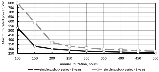
Figure 6.
Maximum rated power vs. annual utilization (diesel fuel price—USD/L). Source: developed by authors.
Work on the development of a Rankine cycle heat recovery system began back in the 1970s. It was funded by the U.S. Department of Energy and conducted by Mack Trucks and Thermo Electron Corporation [39].
BMW engineers tested a system using a recycled steam engine on a passenger car. This resulted in a 10% increase in torque and a 15% reduction in specific fuel consumption. The mass of the additional components exceeded 100 kg. This scheme was called Turbosteamer, and its first version was adapted for a BMW 3 series passenger car [40].
Research in this direction is being carried out by a number of companies, including AVL Power Train Engineering, Inc. (Plymouth, MI, USA); Cummins (Columbus, IN, USA); Navistar Advanced Technology (Lisle, IL, USA), etc. Simulations of recycling systems using the Rankine cycle show that the potential reduction in specific fuel consumption ranges from 6 to 11%, depending on the type of working fluid [41]. Organic Rankine Cycle systems are already in commercial use in marine and stationary power plants. However, their application in agricultural vehicles is still being researched and is expected to enter the market by 2020.
Cooling by injecting water into the airflow at the compressor inlet is widely used in gas turbines [42]. The temperature drops to the dew point temperature and does not exceed 10 °C in most climates.
Air cooling in recuperative heat exchangers provides greater temperature reduction. The cold needed to cool the outside air can be obtained in a heat-utilizing refrigerating machine (HRM) by using the heat of the exhaust gases. Studies show that the HRM ejector is the simplest and most reliable, with the working medium being a liquid with a low boiling point [43]. Modeling of the process shows that the decrease in air temperature for gas turbines (at an exhaust gas temperature of 450 °C) is 40…60 °C [44].
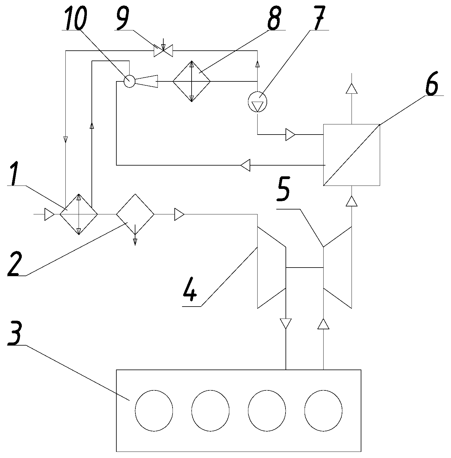
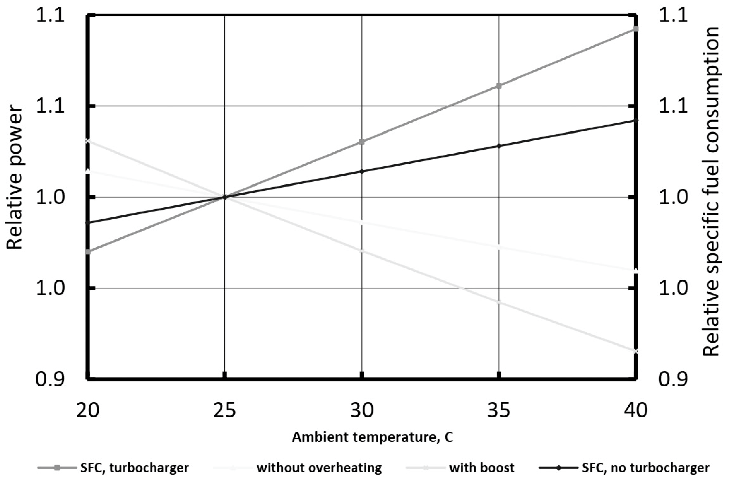
This technology can also be used for engines of agricultural machinery (Figure 7). Calculations based on standards [18] show that in summer, it is possible to increase the power of diesel engines by 10% and reduce the specific fuel consumption by up to 9% (Figure 8). This is because summer temperatures can help cool the air better, allowing the engine to operate more efficiently. In warm weather, the air is generally less dense, which can help the fuel burn better if the engine’s injection and cooling systems are optimized. Summer temperatures can improve cooling systems, helping the engine run more consistently and efficiently. More consistent operating conditions can result in increased power and lower specific fuel consumption. When technologies such as water vapor injection or improved cooling systems are used, they can help ensure more complete and efficient combustion of the fuel. This can result in increased engine power and reduced specific fuel consumption. In some cases, fuel with improved properties or additives can be used in the summer to help burn more efficiently and improve overall engine performance.
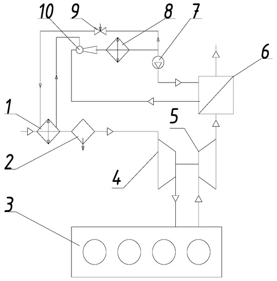
Figure 7.
Heat recovery scheme for air cooling: 1—evaporative air cooler; 2—condensate trap; 3—engine; 4—compressor; 5—turbine; 6—recycling boiler; 7—pump; 8—working fluid condenser; 9—throttle valve; 10—ejector.

Figure 8.
Power and specific fuel consumption as a function of air temperature. Source: developed by authors.
The recirculating chiller can be used to cool the air after the air cleaner, improving the efficiency of the air cooler and TEG. Obviously, this device is most effective at relatively high air temperatures and can be recommended for agricultural machinery that works at high air temperatures, such as combines.
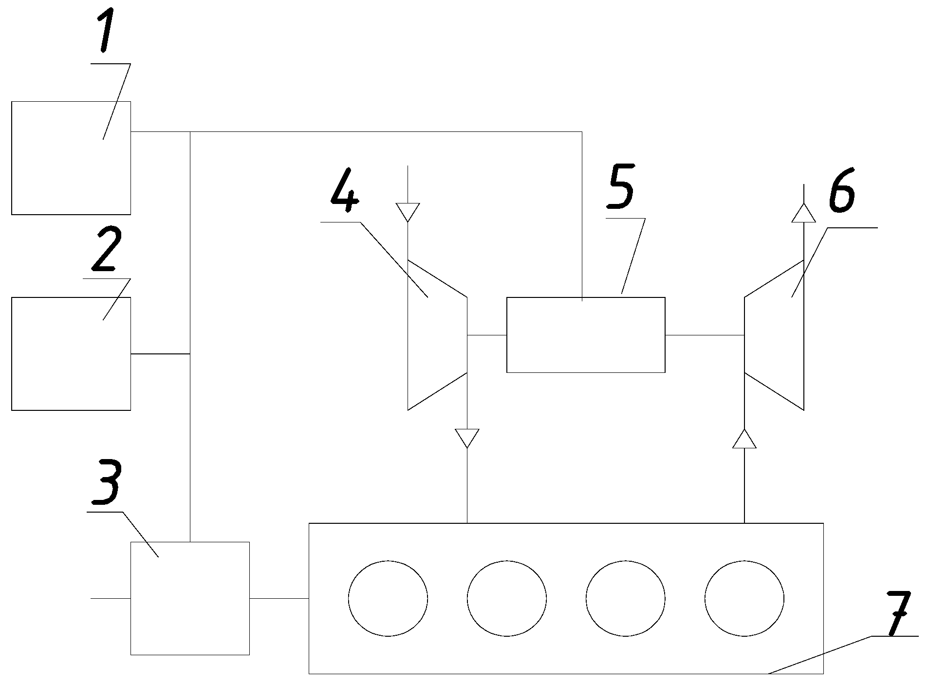
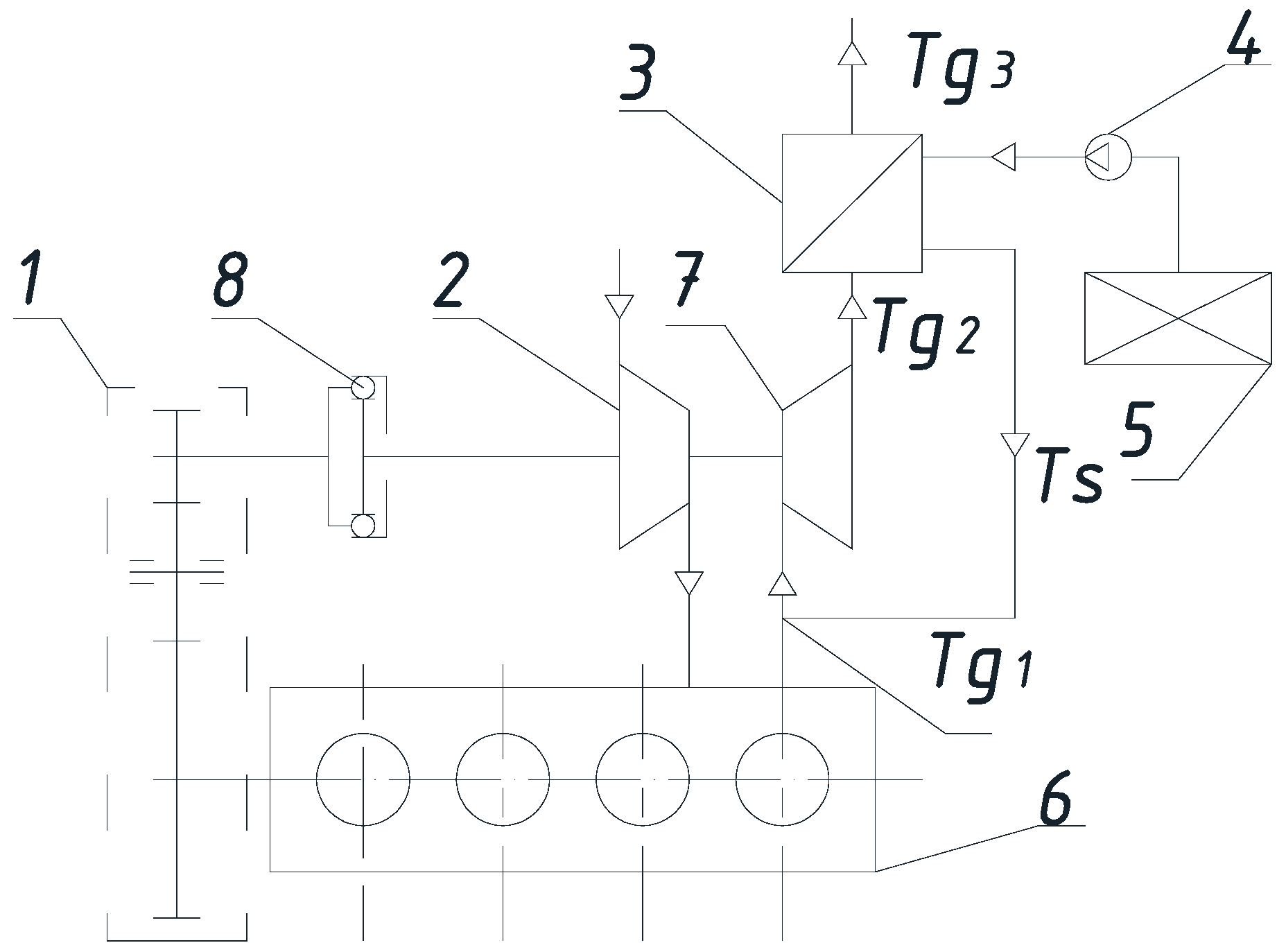
Steam injection into the combustion chamber is used to improve technical and economic indicators of gas turbines. Such equipment is also produced in Ukraine [45], which is suggested to be used for an internal combustion engine (Figure 9). Steam is proposed to be injected into the turbocharger turbine. This makes it possible to reduce the number of elements of the heat recovery system and, consequently, its cost.
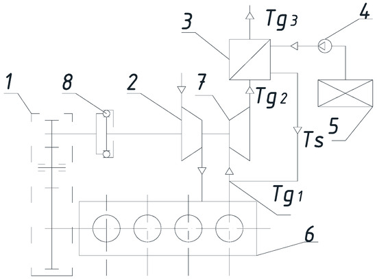
Figure 9.
Scheme of heat utilization: 1—reducer; 2—compressor; 3—recycling boiler; 4—feeding pump; 5—water tank; 6—internal combustion engine; 7—turbine; 8—overtaking clutch.
By injecting steam vapor directly into the turbine, it can be used more efficiently for cooling and improving combustion. This results in more optimal system operation and a reduced need for additional heat recovery components. The use of steam allows functions that previously required separate components to be integrated into the turbine itself. This simplifies the system design and reduces the number of components required, such as additional heat exchangers and pumps. Fewer components means lower costs to manufacture and install the system. This reduces the overall cost of the heat recovery system by reducing the number of complex and expensive components. By injecting steam into the turbine, the system becomes more compact and efficient, reducing its cost and simplifying its design.
A portion of the exhaust gases is recirculated for internal disposal. This allows improvements in the efficiency of the engine only at partial loads. It should be noted that the mentioned solution is mainly used to reduce the level of toxicity of diesel engines of agricultural mobile energy vehicles [46]. Exhaust gas recirculation is used as an internal recycling tool to reduce the toxicity level of diesel engines. It allows a portion of the exhaust gases to be returned to the engine’s combustion chamber. This reduces the oxygen concentration and increases the carbon dioxide content in the combustion chamber, which helps to reduce the formation of nitrogen oxides (NOx), which are toxic substances. At partial loads, the engine operates under conditions that may be less than optimal for reducing toxicity. Exhaust gas recirculation helps maintain a more stable and cleaner combustion under these conditions. This technology is particularly relevant for mobile agricultural machinery, where the need to reduce exhaust toxicity is high due to the long and intensive use of the engines under various conditions.
The devices for injecting water vapor into the internal combustion engine include: a reducer 1, a compressor 2, a recovery boiler 3, a feeding pump 4, a water tank 5, an internal combustion engine 6, a turbine 7 and an overtaking clutch 8. The overtaking clutch 8 in the device for injecting steam into the internal combustion engine is used to transmit rotary motion and prevent reverse torque from the turbine to the engine.
Figure 9 shows that —temperature of exhaust gases before turbine 7, —temperature of exhaust gases after expansion in turbine 7, —temperature after recovery boiler 3, and —temperature of saturated steam.
The device works as follows [45]. When the internal combustion engine 6 is running with fuel from the combustion chamber, the exhaust gases flow to the turbine 7, which is rigidly mounted on one shaft with the compressor 2, which injects air into the combustion chamber of the internal combustion engine 6. After the combustion engine 6 has been heated up and discharged from the water tank 5 with the help of the feed pump 4 to the nominal operating power (the temperature of the exhaust gases is about 925 K), the water is pumped to the boiler 3, where the water begins to turn into saturated steam due to heating from the exhaust gases. The saturated water vapor formed is fed to the turbine 7 and is thus combined with the exhaust gases coming from the combustion chamber of the internal combustion engine 6. At the same time, the compressor 2, which is rigidly mounted on one shaft by the turbine 7, begins to rotate at an additional increased speed and pumps a larger amount air into the combustion chamber of the internal combustion engine 6. Due to the excess power of the turbine 7, it transmits the torque of the drive shaft of the reducer 1, to the driven shaft of the reducer 1, which is connected to the crankshaft of the internal combustion engine, through the overtaking clutch 8.
The mathematical model for determining the effect of the specified recycling scheme on the economic and performance indicators of the engine showed that the temperature of the exhaust gases of the internal combustion engine before the turbocharger at the rated power mode is approximately 925 K. The temperature of gases Tg2 after expansion in the turbine can be determined as follows:
where is the temperature of exhaust gases in front of the turbine, K;
—is the adiabatic temperature drop in the turbine, K;
is the efficiency factor of the turbine.
The decrease in temperature during the adiabatic expansion of gases is:
where is the gas temperature at the exit from the turbine during adiabatic expansion, K;
—specific work of expansion, J/kg;
is the adiabatic coefficient;
is the specific gas constant, J/(kg·K).
The maximum value of the specific work of expansion in one stage of the turbine is 300 kJ/kg. Under such conditions, the temperature of the gas during expansion decreases by about 263 K.
In real internal combustion engines, the expansion of gases in the turbine is not complete. Then, the temperature of the gases after the turbine is:
where , are gas pressure before and after the turbine, respectively;
—coefficient of polytropy;
is the degree of pressure reduction in the turbine.
Let us consider the processes of producing steam, injecting it into the turbine and expansion along with gases. Steam is produced in the recovery boiler. Let us determine the temperatures at the nodal points. The temperature of the mixture of exhaust gases and steam in front of the turbine is determined from the equation:
where is the temperature of saturated water vapor, K;
, —specific isobaric heat capacity of exhaust gases and steam, respectively, kJ/( kg·K);
, —consumption, respectively, of steam and waste gases, kg/s;
is the temperature of the steam–gas mixture, K.
Specific isobaric heat capacities of steam and gases differ by a factor of almost two. Then, the desired value of the temperature of the steam–gas mixture will be:
Let us determine the amount of steam that can be obtained in the utilization boiler. The heat balance of its production is described by the following equations. The amount of heat that is used in steam formation is determined by the formula (from the side of the steam–gas mixture):
where is the temperature behind the utilization boiler, K;
is the efficiency factor of the utilization boiler.
The temperature behind the recovery boiler is determined from the condition of low-temperature corrosion and is approximately 403 K.
Low-temperature corrosion can occur when the exhaust gas temperature is too low, causing acidic components in the gases, such as sulfuric and carbonic acids, to condense, which can damage system materials. The optimum temperature of 403 K minimizes the risk of corrosion while maintaining system efficiency.
The amount of heat that goes into the formation of saturated steam is determined by the equation
where is the specific isobaric heat capacity of water, kJ/(kg·K);
is the heating of water from the initial temperature to the boiling temperature, K;
r is the specific heat of vaporization of water, kJ/kg.
Equating Equations (13) and (14), we determine the amount of steam formed in the utilization boiler:
Equation (13) contains the value of the temperature after the turbine, which depends on the amount of steam. Therefore, it can be solved only by numerical methods, namely the Newton–Raphson Method. It is well suited for solving nonlinear Equation (15) because it uses derivatives to iteratively find the roots of the equation and can be effective if there is a sufficiently good initial approximation.
Let us consider how the injection of steam will affect the parameters of the turbocharger and the diesel engine as a whole. The power of the turbine depends on the adiabatic operation of gases and their consumption:
where is the efficiency factor of the turbine.
Consider the work of compression in a compressor. The power consumed by the compressor is determined by the equation:
where is the degree of pressure increase in the compressor;
is the efficiency factor of the compressor.
The injection of steam into the turbine leads to an increase in its power. It can be transmitted to the crankshaft of the engine.
Calculations for tractors of the third traction class show that at operating power, it is possible to obtain saturated steam in the amount of 0.0145 kg/s (52.2 kg/h). This allows the power of the diesel engine to be increased by 2%. Specific fuel consumption will decrease by the corresponding amount.
Thus, the use of the proposed device will allow the fuel consumption per unit of engine power (specific fuel consumption) to be reduced, as well as the emission of toxic greenhouse gases into the atmosphere; the effective power and thermal efficiency of the internal combustion engine to increase; and the design of the internal combustion engine combustion to be simplified due to additional equipment.
The potential increase in power and decrease in specific fuel consumption under various heat utilization schemes are shown in Table 1.

Table 1.
Potential change in technical parameters of engines under different heat recovery schemes and possible use.
Based on the above, the following classification system of heat recovery systems is proposed.
- According to the source of secondary heat: coolant; engine oil; heat engine parts; exhaust gases.
- According to the type of energy resource that can be obtained: hot water; coupling; mechanical energy; electrical energy.
- Use of the obtained energy resources: hot water (heating system, power supply system, including heating of both liquid and gaseous fuels); injection at the input of a centrifugal compressor; heat accumulator; steam: steam engine/turbine; injection into the turbocharger turbine; electric energy (on-board electrical system power supply, traction electric motor power supply, fuel heating); mechanical energy (transmission to the crankshaft of the engine, fan of the cooling system).
- By types of recycling systems cycles: open (injection of superheated water into the compressor, injection of steam into the turbine); closed (Rankin cycle).
- By type of working fluid in utilization cycles: water; liquids with a low boiling point.
- By type of disposal: external; internal.
- According to the purpose of the disposal system: improvement in environmental indicators; improvement in economic indicators of the engine; ensuring the needs of external consumers.
- According to the thermal potential of the secondary coolant: high temperature (exhaust gases); low temperature (coolant, compressed air, engine oil).
The classification by type of disposal (external and internal) requires some explanation. External utilization uses diesel heat to meet the needs of consumers not related to the engine (interior heating system, air conditioning system, etc.). Internal recycling is aimed at increasing the performance and environmental and economic indicators of the engine itself and related systems. The given scheme does not consider in detail the classification of gas turbine supercharging systems, as it is given in many scientific works and training manuals.
3. Conclusions
Intensive work is being performed in the world to increase the efficiency of engines of mobile energy vehicles, including through the use of heat. Based on the analysis of existing and proposed heat utilization schemes, their classification has been developed. The use of such heat utilization schemes as the injection of water vapor into the turbocompressor turbine and the use of a utilization refrigerating machine are proposed.
Agricultural vehicles have different operating characteristics. This study identifies several advanced technologies for such vehicles, including turbocompounding and system heating. Their efficiency is influenced by annual usage and fuel cost. For turbocompounding to be economically viable in the EU, the minimum rated power required is 308 kW for agricultural tractors and 388 kW for combine harvesters, and engines of this power are already in production.
In cold climates or seasons, heat accumulators (for initial heating) and exhaust gas heat recovery systems for warming transmission are recommended. Thermal storage is currently in production. Waste heat recovery to heat the lube oil in hydraulic clutches offers high economic efficiency at low temperatures, but this technology is not yet commercially available, despite significant research and testing.
In hot climates or seasons, particularly for combine harvesters, absorption refrigeration systems are feasible for air conditioning and intake air cooling. These systems, with a coefficient of performance of about 0.2, show potential for economic efficiency.
It is necessary to continue work on the substantiation of parameters of disposal systems for different classes of mobile energy vehicles. It is advisable to develop a methodology for the substantiation of the range of effective application of heat utilization systems in agricultural mobile energy vehicles.
In order to increase the efficiency of the internal combustion engine, it is possible to use the heat of exhaust gases with a minimum amount of additional equipment. For this purpose, steam obtained in the recovery boiler is injected into the turbine.
Directions for further research:
- -
- Development of calculation methodology and computer program for its implementation;
- -
- Determination of the influence of turbocompressor parameters on the efficiency of the proposed disposal system;
- -
- Determination of the direction of use of excess turbine power (increase in air pressure after the compressor and its performance or transfer to the engine crankshaft);
- -
- Economic efficiency depending on the engine and turbocharger parameters.
Author Contributions
Conceptualization, V.H. and A.K.; methodology, A.K., D.M. and V.H.; software, D.M.; validation, A.K., D.M. and V.H.; formal analysis, V.H. and A.K.; investigation, V.H. and D.M.; resources, D.M.; data curation, A.K., D.M. and V.H.; writing—original draft preparation, A.K., D.M. and V.H.; writing—review and editing, A.K., D.M. and V.H.; visualization, D.M.; supervision, V.H.; project administration, A.K.; funding acquisition, A.K. All authors have read and agreed to the published version of the manuscript.
Funding
This work was supported by the project “Supporting the cooperation of the University of Opole with Ukrainian universities within the FORTHEM Alliance 2024”. Publishing this paper was financed by the Polish Agency for Academic Exchange, agreement No. BNI-UE-2023-9.
Institutional Review Board Statement
Not applicable.
Informed Consent Statement
Not applicable.
Data Availability Statement
The data presented in this study are available on request from the corresponding author.
Acknowledgments
We are grateful to the Armed Forces of Ukraine that we can engage in scientific research.
Conflicts of Interest
The authors declare no conflicts of interest.
References
- Jadin, D.W.; Nine, R. Super Truck—Development and Demonstration of a Fuel Efficiency Class 8 Tractor & Trailer. Engine Systems. Doe Merit Review. 2012. Available online: https://www1.eere.energy.gov/vehiclesandfuels/pdfs/merit_review_2012/veh_sys_sim/vss064_jadin_2012_o.pdf (accessed on 1 July 2024).
- Lunyaka, K.; Kliuiev, O.; Rusanov, S.; Kliuieva, O. The research of the work of the heat accumulator of the pre-starting system of worming up of the internal combustion engine. Thermophys. Therm. Power Eng. 2020, 42, 76–83. [Google Scholar] [CrossRef]
- Kuhtik, N. Improving of Fuel Economy and Ecologic Indicators of Modern Cars by Rational Engine Warm-Up. Ph.D. Thesis, National Transport University, Kyiv, Ukraine, 2021. Available online: https://uacademic.info/en/document/0821U102716 (accessed on 1 July 2024).
- Crower, H.B.; Mathews, W.W. Free Piston Pressure Spike Modulator for any Internal Combustion Engine. U.S. Patent 7,588,000 B2, 15 September 2009. Available online: https://patents.google.com/patent/US7588000B2/en (accessed on 1 July 2024).
- Thermoelectrics Gaining More Attention and Development Focus. Green Car Congress. 22 July 2005. Available online: https://www.greencarcongress.com/2005/07/thermoelectrics.html (accessed on 1 July 2024).
- Liere, J.; Meijer, C.G.; Laagland, G. Power Augmentation and NOx Reduction of Gas Turbines by Swirlflash® over Spray. 2002. Available online: https://www.researchgate.net/publication/293063196_Power_augmentation_and_NOx_reduction_of_gas_turbines_by_swirlflashR_over_spray (accessed on 1 July 2024).
- Greszler, A. Diesel Turbo-Compound Technology. ICCT/NESCCAF Workshop Improving the Fuel Economy of Heavy-Duty Fleets. 20 February 2008. Available online: http://www.nescaum.org/documents/improving-the-fuel-economy-of-heavy-duty-fleets-1/greszler_volvo_session3.pdf (accessed on 1 July 2024).
- Tennant, D.; Walsham, B. The Turbocompound Diesel Engine; SAE Technical Paper; SAE International: Warrendale, PA, USA, 1989; p. 890647. [Google Scholar] [CrossRef]
- Wilson, D. The Design of a Low Specific Fuel Consumption Turbocompound Engine; SAE Technical Paper; SAE International: Warrendale, PA, USA, 1986; p. 860072. [Google Scholar] [CrossRef]
- Brands, M.C.; Werner, J.; Hoehne, J.L.; Kramer, S. Vehicle Testing of Cummins Turbocompound Diesel Engine; SAE Technical Paper; SAE International: Warrendale, PA, USA, 1981; p. 810073. [Google Scholar] [CrossRef]
- Hopmann, U. Diesel Engine Waste Heat Recovery Utilizing Electric Turbocompound Technology. In Proceedings of the DEER Conference 2002, San Diego, CA, USA, 25–29 August 2002; Available online: http://www1.eere.energy.gov/vehiclesandfuels/pdfs/deer_2002/session8/2002_deer_hopmann.pdf (accessed on 1 July 2024).
- Velidi, G.; Yoo, C.S. A Review on Flame Stabilization Technologies for UAV Engine Micro-Meso Scale Combustors: Progress and Challenges. Energies 2023, 16, 3968. [Google Scholar] [CrossRef]
- Hopmann, U. Diesel engine waste heat recovery utilizing electric turbocompound technology. In Proceedings of the DEER Conference 2004, San Diego, CA, USA, 30 August–2 September 2004; Available online: https://www.energy.gov/sites/prod/files/2014/03/f9/2004_deer_hopmann.pdf (accessed on 1 July 2024).
- Parimal, P.S.; Doyle, E.F. Compounding the Truck Diesel Engine with an Organic Rankine Cycle System; SAE Technical Paper; SAE International: Warrendale, PA, USA, 1976; p. 760343. [Google Scholar] [CrossRef]
- Freymann, R.; Strobl, W.; Obieglo, A. The Turbosteamer: A System Introducing the Principle of Cogeneration in Automotive Application. MTZ 05 2008, 69, 404–412. Available online: https://connect.forcemotors.com/Employee_Information/library_doc/MTZ/may_06.pdf (accessed on 1 July 2024). [CrossRef]
- Hountalas, D.T.; Mavropoulos, G.C. Potential for Improving HD Diesel Truck Engine Fuel Consumption Using Exhaust Heat Recovery Techniques. New Trends Technol. Devices Comput. Commun. Ind. Syst. 2010, 17, 313–340. [Google Scholar] [CrossRef]
- Bhargava, R.; Meher-Homji, C.B. Parametric Analysis of Existing Gas Turbines With Inlet Evaporative and Overspray Fogging. In Proceedings of the ASME Turbo Expo 2002: Power for Land, Sea, and Air, Amsterdam, The Netherlands, 3–6 June 2002; Volume 4, pp. 387–401. [Google Scholar] [CrossRef]
- Nixdorf, M.; Prelipceanu, A.; Hein, D. Thermo-economic analysis of inlet air conditioning methods of a cogeneration gas turbine plant. In Proceedings of the ASME TURBO EXPO 2002: Ceramics, Industrial and Cogeneration Structures and Dynamics, Amsterdam, The Netherlands, 3–6 June 2002; pp. 403–412. [Google Scholar] [CrossRef]
- The Engine That Redefines Versatility. Available online: https://www.volvotrucks.us/trucks/powertrain/d13tc/ (accessed on 17 July 2018).
- Diesel Engine 6R 1500 for Agriculture and Forestry Applications with EPA Tier 4 and EU Stage IV Certification. Available online: https://mtupartssuppliers.wordpress.com/2018/06/20/mtu-series-1500/ (accessed on 17 October 2018).
- Detroit Diesel DD15. Available online: http://literature.puertoricosupplier.com/018/OT17636.pdf (accessed on 17 October 2018).
- Mack MP8 with Turbo Compounding Now Available for Order. Available online: https://www.volvogroup.com/en/news-and-media/news/2017/mar/mack-mp-8-with-turbo-compounding-nowp-available-for-order.html (accessed on 12 September 2024).
- Andrienko, A.A. Results of the Development and Research of a Turbofan for the Cooling System of a Turbo-Diesel Engine. Available online: http://engine.aviaport.ru/issues/59/page14.html (accessed on 10 June 2018).
- Daccord, R. Cost to benefit ratio of an exhaust heat recovery system on a long haul truck. Energy Procedia 2017, 129, 740–745. [Google Scholar] [CrossRef]
- Mack Trucks Unleashes 2017 Engine Lineup, Boosting Power, Productivity and Efficiency. Available online: https://www.volvogroup.com/en/news-and-media/news/2016/apr/news-151806.html (accessed on 12 September 2024).
- Volvo D13 Turbo Compound Engine Powers New Volvo VNL Series to 7.5 Percent Improvement in Fuel Efficiency. Available online: https://www.volvotrucks.us/news-and-stories/press-releases/2017/july/volvo-d13-turbo-compound-engine-powers-new-volvo-vnl-series/ (accessed on 29 June 2018).
- Diesel Prices, 18 June 2018 (USD/l). Available online: https://www.globalpetrolprices.com/diesel_prices/ (accessed on 18 June 2018).
- Energy Efficiency and Energy Savings. The Economist Intelligence Unit Limited. 2012. Available online: https://library.gbpn.org/resource/energy-efficiency-and-energy-savings-view-building-sector-1 (accessed on 19 July 2018).
- Increased Profitability for Independent Power Producers. Available online: https://www.bowmanpower.com/ (accessed on 20 July 2018).
- John Deere 7430 E Premium. Available online: https://www.tractordata.com/farm-tractors/005/2/3/5234-john-deere-7430-premium.html (accessed on 12 July 2018).
- Karner, J.; Prankl, H.; Kogler, F. Electric Drives in Agricultural Machinery. In Proceedings of the International Conference Energy, Biomass and Biological Residues. International Conference of Agricultural Engineering—CIGR-AgEng 2012: Agriculture and Engineering for a Healthier Life, Valencia, Spain, 8–12 July 2012. [Google Scholar]
- Drive Axle PowerDriveElect—Transport Concepts with Drive Axles over the Course of Time. Fliegl Agrartechnik. Available online: https://fliegl-agrartechnik.de/en/ (accessed on 14 July 2018).
- Mckelkamp, M. Kinze’s 4900 Series Electric Planter, 4000 Series Row Unit and Electric Meter. 2013. Available online: https://www.kinze.com/kinze-unveils-new-4900-planter/ (accessed on 14 July 2018).
- UX eSpray Trailed Sprayer. Amazone, 2010. GO for Innovation. Available online: http://info.amazone.de/DisplayInfo.aspx?id=14005 (accessed on 14 July 2018).
- Electrically-Powered Kuhn/Rauch Fertilizer Spreaders Offer Ultra-Accurate Application. Farmers Weekly. 9 October 2007. Available online: https://www.fwi.co.uk/machinery/electrically-powered-kuhn-rauch-fertiliser-spreaders-offer-ultra-accurate-application (accessed on 10 July 2018).
- Aixala, L. RENOTER Project. 3rd Thermoelectric Applications Workshop: 20–22 March 2012 in Baltimore (MI). Available online: https://www1.eere.energy.gov/vehiclesandfuels/pdfs/thermoelectrics_app_2012/tuesday/aixala.pdf (accessed on 19 July 2018).
- Champier, D. Thermoelectric generators: A review of applications. Energy Convers. Manag. 2017, 140, 167–181. [Google Scholar] [CrossRef]
- Cherednichenko, A.K.; Tkach, M.R.; Timoshevsky, B.G.; Proskurin, A.Y. Thermochemical Heat Recovery Efficiency of the “River-Sea” Ship Power Plants. Available online: https://www.khai.edu/csp/nauchportal/Arhiv/AKTT/2016/AKTT816/Cherednichenko.pdf (accessed on 3 June 2018).
- Ibrahim, T.M.; Syahir, A.Z.; Zulkifli, N.W.M.; Masjuki, H.H.; Osman, A. Enhancing vehicle’s engine warm up using integrated mechanical approach. IOP Conf. Ser. Mater. Sci. Eng. 2017, 210, 012064. [Google Scholar] [CrossRef]
- Kauranen, P.; Heikkinen, J.; Laurikko, J.; Seppala, A. Heat and Cold Accumulator in Vehicles. Available online: https://www.osti.gov/etdeweb/biblio/966848 (accessed on 10 July 2018).
- Mondejar, E.; Andreasen, J.G.; Pierobon, L.; Larsen, U.; Thern, M.; Haglind, F. A review of the use of organic Rankine cycle power systems for maritime applications. Renew. Sustain. Energy Rev. 2018, 91, 126–151. [Google Scholar] [CrossRef]
- Ivannikov, A.B. Secondary Use of the Heat of the Engine Exhaust Gases to Improve the Performance of the Units by the Example of the Transmission of the Tractor; Candidate of Technical Sciences; Novosibirsk State Agrarian University: Novosibirsk, Russia, 2017. [Google Scholar]
- Kalinichenko, A.; Havrysh, V.; Hruban, V. Heat Recovery Systems for Agricultural Vehicles: Utilization Ways and Their Efficiency. Agriculture 2018, 8, 199. [Google Scholar] [CrossRef]
- Marchenko, D.; Matvyeyeva, K.; Kurepin, V. Development of Methods for Digital Diagnostics of Engines by Electronic Indication. In Proceedings of the 2022 IEEE 4th International Conference on Modern Electrical and Energy System, Kremenchuk, Ukraine, 20–22 October 2022. [Google Scholar] [CrossRef]
- Marchenko, D.; Matvyeyeva, K. Development and Research of an Automatic System for Regulating the Frequency of Rotation of a Diesel Engine Crankshaft. In Proceedings of the IEEE 5th International Conference on Modern Electrical and Energy System, Kremenchuk, Ukraine, 27–30 September 2023. [Google Scholar] [CrossRef]
- Havrysh, V.; Marchenko, D.; Kalinichenko, A. Device for Injecting Water Vapor into an Internal Combustion Engine. Patent of Ukraine for a Utility Model u201802430, 10 December 2018. Available online: https://sis.nipo.gov.ua/en/search/detail/396062/ (accessed on 24 September 2024).


Disclaimer/Publisher’s Note: The statements, opinions and data contained in all publications are solely those of the individual author(s) and contributor(s) and not of MDPI and/or the editor(s). MDPI and/or the editor(s) disclaim responsibility for any injury to people or property resulting from any ideas, methods, instructions or products referred to in the content. |
© 2024 by the authors. Licensee MDPI, Basel, Switzerland. This article is an open access article distributed under the terms and conditions of the Creative Commons Attribution (CC BY) license (https://creativecommons.org/licenses/by/4.0/).