
Improved Performance of Bifacial Photovoltaic Modules with Low-Temperature Processed Textured Rear Reflector


Abstract
:1. Introduction
2. Experiments and Methodology
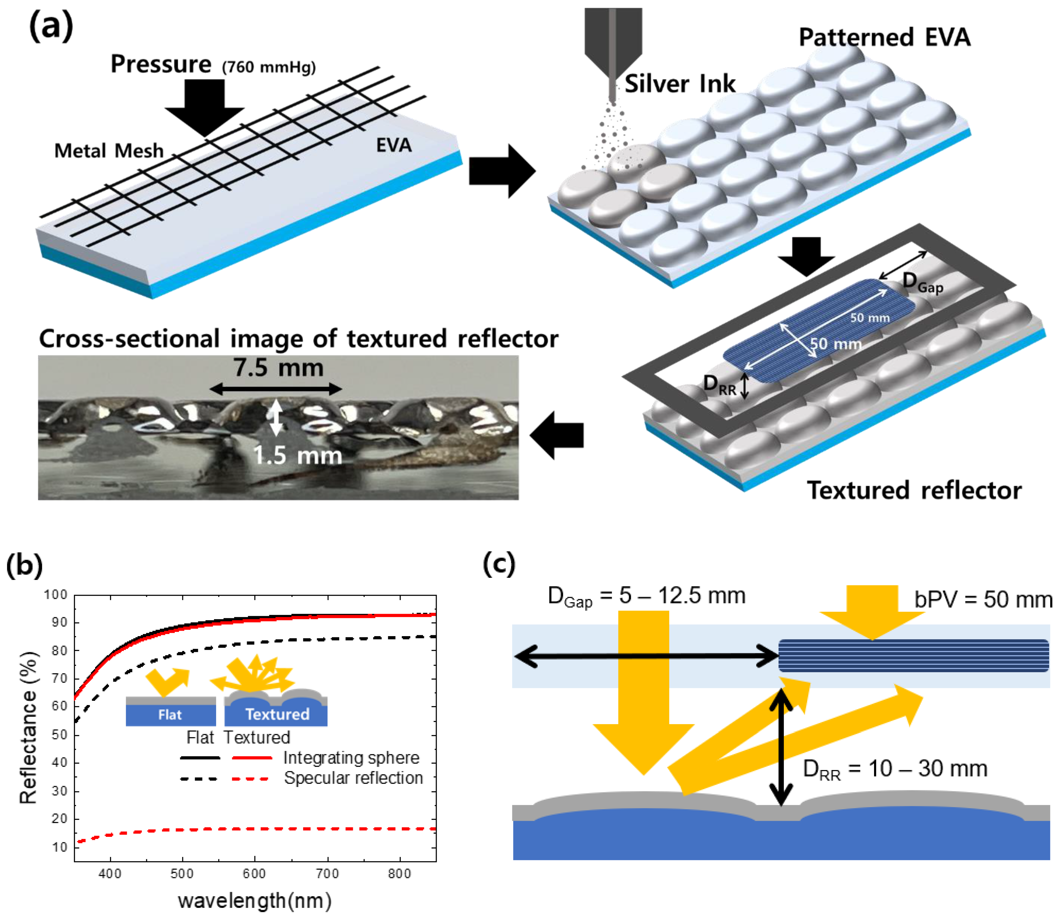
2.1. Fabrication of bPV with Textured Reflector
2.2. Measurement of bPVs
3. Results and Discussion
4. Conclusions
Author Contributions
Funding
Institutional Review Board Statement
Informed Consent Statement
Data Availability Statement
Conflicts of Interest
References
- Liang, T.S.; Pravettoni, M.; Deline, C.; Stein, J.S.; Kopecek, R.; Singh, J.P.; Luo, W.; Wang, Y.; Aberle, A.G.; Khoo, Y.S. A review of crystalline silicon bifacial photovoltaic performance characterisation and simulation. Energy Environ. Sci. 2019, 12, 116–148. [Google Scholar] [CrossRef]
- González-Moreno, A.; Mazzeo, D.; Dolara, A.; Ogliari, E.; Leva, S. Outdoor Performance Comparison of Bifacial and Monofacial Photovoltaic Modules in Temperate Climate and Industrial-like Rooftops. Appl. Sci. 2024, 14, 5714. [Google Scholar] [CrossRef]
- Tonita, E.M.; Valdivia, C.E.; Russell, A.C.J.; Martinez-Szewczyk, M.; Bertoni, M.I.; Hinzer, K. A general illumination method to predict bifacial photovoltaic system performance. Joule 2023, 7, 5–12. [Google Scholar] [CrossRef]
- Tonita, E.M.; Valdivia, C.E.; Russell, A.C.J.; Martinez-Szewczyk, M.; Bertoni, M.I.; Hinzer, K. Quantifying spectral albedo effects on bifacial photovoltaic module measurements and system model predictions. Prog. Photovolt. Res. Appl. 2024, 32, 468–480. [Google Scholar] [CrossRef]
- Yusufoglu, U.A.; Pletzer, T.M.; Koduvelikulathu, L.J.; Comparotto, C.; Kopecek, R.; Kurz, H. Analysis of the Annual Performance of Bifacial Modules and Optimization Methods. IEEE J. Photovolt. 2015, 5, 320–328. [Google Scholar] [CrossRef]
- Gu, W.; Ma, T.; Ahmed, S.; Zhang, Y.; Peng, J. A comprehensive review and outlook of bifacial photovoltaic (bPV) technology. Energy Convers. Manag. 2020, 223, 113283. [Google Scholar] [CrossRef]
- Gu, W.; Li, S.; Liu, X.; Chen, Z.; Zhang, X.; Ma, T. Experimental investigation of the bifacial photovoltaic module under real conditions. Renew. Energy 2021, 173, 1111–1122. [Google Scholar] [CrossRef]
- Katsikogiannis, O.A.; Ziar, H.; Isabella, O. Integration of bifacial photovoltaics in agrivoltaic systems: A synergistic design approach. Appl. Energy 2022, 309, 118475. [Google Scholar] [CrossRef]
- Kopecek, R.; Libal, J.; Photovoltaics, B. Status, Opportunities and Challenges. Energies 2021, 14, 2076. [Google Scholar] [CrossRef]
- Jang, J.; Lee, K. Practical Performance Analysis of a Bifacial PV Module and System. Energies 2020, 13, 4389. [Google Scholar] [CrossRef]
- Hwang, S.; Kang, Y.; Lee, H.-S. Performance and energy loss mechanism of bifacial photovoltaic modules at a solar carport system. Energy Sci. Eng. 2023, 11, 2866–2884. [Google Scholar] [CrossRef]
- Pan, N.; Ghosh, S.; Hasan, M.N.; Ahmed, S.A.; Chatterjee, A.; Patwari, J.; Bhattacharya, C.; Qurban, J.; Khder, A.S.; Pal, S.K. Plasmon-Coupled Donor–Acceptor Type Organic Sensitizer-Based Photoanodes for Enhanced Photovoltaic Activity: Key Information from Ultrafast Dynamical Study. Energy Fuels 2022, 36, 9272–9281. [Google Scholar] [CrossRef]
- Lee, H.; Cho, D.-H.; Lim, C.; Kim, W.; Jang, Y.H.; Baek, S.-W.; Ju, B.K.; Lee, P.; Yu, H. Pressurized Back-Junction Doping via Spray-Coating Silver Nanowires Top Electrodes for Efficient Charge Collection in Bifacial Colloidal PbS Quantum Dot Solar Cells. ACS Appl. Mater. Interfaces 2024, 16, 7130–7140. [Google Scholar] [CrossRef] [PubMed]
- Song, Z.; Li, C.; Chen, L.; Yan, Y. Perovskite Solar Cells Go Bifacial—Mutual Benefits for Efficiency and Durability. Adv. Mater. 2022, 34, 2106805. [Google Scholar] [CrossRef]
- Galdino, J.J.B.; Vilela, O.D.C.; Fraidenraich, N.; Gómez-Malagón, L.A. Evaluation of front and backside performances of a large surface organic photovoltaic module under bifacial illumination. Sol. Energy Mater. Sol. Cells 2023, 257, 112359. [Google Scholar] [CrossRef]
- Qian, C.; Sun, K.; Cong, J.; Cai, H.; Huang, J.; Li, C.; Cao, R.; Liu, Z.; Green, M.; Hoex, B.; et al. Bifacial and Semitransparent Sb2(S,Se)3 Solar Cells for Single-Junction and Tandem Photovoltaic Applications. Adv. Mater. 2023, 35, 2303936. [Google Scholar] [CrossRef]
- Li, C.; Zhang, W.; Wu, J.; Lyu, Y.; Tang, H. Experimental study of a vertically mounted bifacial photovoltaic sunshade. Renew. Energy 2023, 219, 119518. [Google Scholar] [CrossRef]
- Soria, B.; Gerritsen, E.; Lefillastre, P.; Broquin, J.-E. A study of the annual performance of bifacial photovoltaic modules in the case of vertical facade integration. Energy Sci. Eng. 2016, 4, 52–68. [Google Scholar] [CrossRef]
- Zhang, Y.; Gao, J.Q.; Yu, Y.; Shi, Q.; Liu, Z. Influence of incidence angle effects on the performance of bifacial photovoltaic modules considering rear-side reflection. Sol. Energy 2022, 245, 404–409. [Google Scholar] [CrossRef]
- Tina, G.M.; Scavo, F.B.; Aneli, S.; Gagliano, A. Assessment of the electrical and thermal performances of building integrated bifacial photovoltaic modules. J. Clean. Prod. 2021, 313, 127906. [Google Scholar] [CrossRef]
- Kang, J.-G.; Kim, J.-H.; Kim, J.-T. Design Elements and Electrical Performance of a Bifacial BIPV Module. Int. J. Photoenergy 2016, 2016, 6943936. [Google Scholar] [CrossRef]
- Li, Z.; Zhang, W.; He, B.; Xie, L.; Chen, M.; Li, J.; Zhao, O.; Wu, X. A comprehensive life cycle assessment study of innovative bifacial photovoltaic applied on building. Energy 2022, 245, 123212. [Google Scholar] [CrossRef]
- Zhong, J.; Zhang, W.; Xie, L.; Zhao, O.; Wu, X.; Zeng, X.; Guo, J. Development and challenges of bifacial photovoltaic technology and application in buildings: A review. Renew. Sustain. Energy Rev. 2023, 187, 113706. [Google Scholar] [CrossRef]
- Kim, C.; Jeong, M.S.; Ko, J.; Ko, M.; Kang, M.G.; Song, H.-J. Inhomogeneous rear reflector induced hot-spot risk and power loss in building-integrated bifacial c-Si photovoltaic modules. Renew. Energy 2021, 163, 825–835. [Google Scholar] [CrossRef]
- Raina, G.; Sinha, S. A comprehensive assessment of electrical performance and mismatch losses in bifacial PV module under different front and rear side shading scenarios. Energy Convers. Manag. 2022, 261, 115668. [Google Scholar] [CrossRef]
- Tsuchida, S.; Tsuno, Y.; Sato, D.; Oozeki, T.; Yamada, N. Albedo-Dependent Bifacial Gain Losses in Photovoltaic Modules with Rear-Side Support Structures. IEEE J. Photovolt. 2023, 13, 938–944. [Google Scholar] [CrossRef]
- Deline, C.; Pelaez, S.A.; MacAlpine, S.; Olalla, C. Estimating and parameterizing mismatch power loss in bifacial photovoltaic systems. Prog. Photovolt. Res. Appl. 2020, 28, 691–703. [Google Scholar] [CrossRef]
- Ganesan, K.; Winston, D.P.; Nesamalar, J.J.D.; Pravin, M. Output power enhancement of a bifacial solar photovoltaic with upside down installation during module defects. Appl. Energy 2024, 353, 122070. [Google Scholar] [CrossRef]
- Ko, S.W.; Ju, Y.C.; Hwang, H.M.; So, J.H.; Jung, Y.-S.; Song, H.-J.; Song, H.-E.; Kim, S.-H.; Kang, G.H. Electric and thermal characteristics of photovoltaic modules under partial shading and with a damaged bypass diode. Energy 2017, 128, 232–243. [Google Scholar] [CrossRef]
- Shin, W.G.; Ko, S.W.; Song, H.J.; Ju, Y.C.; Hwang, H.M.; Kang, G.H. Origin of Bypass Diode Fault in c-Si Photovoltaic Modules: Leakage Current under High Surrounding Temperature. Energies 2018, 11, 2416. [Google Scholar] [CrossRef]
- Ko, J.; Kim, C.; Lee, D.; Lee, S.; Shin, W.G.; Kang, G.H.; Oh, J.; Ko, S.W.; Song, H.-J. Real-Time Detection and Classification of Bypass Diode-Related Faults in Photovoltaic Modules via Thermoelectric Devices. Adv. Mater. Technol. 2024, 9, 2301209. [Google Scholar] [CrossRef]
- Muehleisen, W.; Loeschnig, J.; Feichtner, M.; Burgers, A.R.; Bende, E.E.; Zamini, S.; Yerasimou, Y.; Kosel, J.; Hirschl, C.; Georghiou, G.E. Energy yield measurement of an elevated PV system on a white flat roof and a performance comparison of monofacial and bifacial modules. Renew. Energy 2021, 170, 613–619. [Google Scholar] [CrossRef]
- Yang, Y.; O’Brien, P.G.; Ozin, G.A.; Kherani, N.P. See-through amorphous silicon solar cells with selectively transparent and conducting photonic crystal back reflectors for building integrated photovoltaics. Appl. Phys. Lett. 2013, 103, 221109. [Google Scholar] [CrossRef]
- Wang, J.; Xuan, Y.; Da, Y.; Xu, Y.; Zheng, L. Benefits of photonic management strategy for highly efficient bifacial solar cells. Opt. Commun. 2020, 462, 125358. [Google Scholar] [CrossRef]
- Ko, M.; Lee, G.; Kim, C.; Lee, Y.; Ko, J.; Song, H.-J. Dielectric/metal/dielectric selective reflector for improved energy efficiency of building integrated bifacial c-Si photovoltaic modules. Curr. Appl. Phys. 2021, 21, 101–106. [Google Scholar] [CrossRef]
- Zauner, M.; Muehleisen, W.; Holzmann, D.; Baumgart, M.; Oreski, G.; Feldbacher, S.; Feichtner, M.; Nemitz, W.; Leiner, C.; Sommer, C.; et al. Light guidance film for bifacial photovoltaic modules. Renew. Energy 2022, 181, 604–615. [Google Scholar] [CrossRef]
- Choi, S.-W.; Park, J.-H.; Seo, J.-W.; Mun, C.; Kim, Y.; Song, P.; Shin, M.; Kwon, J.-D. Flexible and transparent thin-film light-scattering photovoltaics about fabrication and optimization for bifacial operation. Npj Flex. Electron. 2023, 7, 17. [Google Scholar] [CrossRef]
- Lim, Y.S.; Lo, C.K.; Kee, S.Y.; Ewe, H.T.; Faidz, A.R. Design and evaluation of passive concentrator and reflector systems for bifacial solar panel on a highly cloudy region—A case study in Malaysia. Renew. Energy 2014, 63, 415–425. [Google Scholar] [CrossRef]
- Geretschläger, K.J.; Wallner, G.M.; Fischer, J. Structure and basic properties of photovoltaic module backsheet films. Sol. Energy Mater. Sol. Cells 2016, 144, 451–456. [Google Scholar] [CrossRef]
- Kim, N.; Lee, S.; Zhao, X.G.; Kim, D.; Oh, C.; Kang, H. Reflection and durability study of different types of backsheets and their impact on c-Si PV module performance. Sol. Energy Mater. Sol. Cells 2016, 146, 91–98. [Google Scholar] [CrossRef]
- Pal, S.S.; Loenhout, F.H.C.V.; Westerhof, J.; Saive, R. Understanding and Benchmarking Ground Reflectors for Bifacial Photovoltaic Yield Enhancement. IEEE J. Photovolt. 2024, 14, 160–169. [Google Scholar] [CrossRef]
- Ernst, M.; Liu, X.; Asselineau, C.A.; Chen, D.; Huang, C.; Lennon, A. Accurate modelling of the bifacial gain potential of rooftop solar photovoltaic systems. Energy Convers. Manag. 2024, 300, 117947. [Google Scholar] [CrossRef]
- Pal, S.; Saive, R. Output Enhancement of Bifacial Solar Modules Under Diffuse and Specular Albedo. In Proceedings of the 2021 IEEE 48th Photovoltaic Specialists Conference (PVSC), Online, 20–25 June 2021; pp. 1159–1162. [Google Scholar]
- Pfeffer, F.; Eisenlohr, J.; Basch, A.; Hermle, M.; Lee, B.G.; Goldschmidt, J.C. Systematic analysis of diffuse rear reflectors for enhanced light trapping in silicon solar cells. Sol. Energy Mater. Sol. Cells 2016, 152, 80–86. [Google Scholar] [CrossRef]
- Yoo, D.; Tillmann, P.; Kraus, T.; Sutter, J.; Harter, A.; Trofimov, S.; Naydenov, B.; Jäger, K.; Hauser, H.; Becker, C. Comparative Optical Analysis of Imprinted Nano-, Micro- and Biotextures on Solar Glasses for Increased Energy Yield. Sol. RRL 2023, 7, 2300071. [Google Scholar] [CrossRef]
- Tao, W.; Wang, Y.; Wang, L.; Wang, L.; Dai, J.; Li, T.; Jin, H.; Du, Y.; Zhang, Z. Optimized White Laminate and Redirecting Film as Back Reflectors for High-Efficiency Monofacial and Bifacial Photovoltaic Modules. ECS J. Solid State Sci. Technol. 2023, 12, 075006. [Google Scholar] [CrossRef]
- Kim, C.; Park, J.H.; Ko, J.; Lee, S.; Kwon, R.G.; Lee, S.; Lee, H.; Kim, J.Y.; Song, H.-J. Room temperature processed protective layer for printed silver electrodes. RSC Adv. 2023, 13, 20557–20564. [Google Scholar] [CrossRef]
- Wu, C.-H.; Liu, C.-Y. Optimization of compression molding for double-concave lenses. Int. J. Adv. Manuf. Technol. 2023, 125, 5089–5099. [Google Scholar] [CrossRef]
- Singh, J.P.; Guo, S.; Peters, I.M.; Aberle, A.G.; Walsh, T.M. Comparison of Glass/Glass and Glass/Backsheet PV Modules Using Bifacial Silicon Solar Cells. IEEE J. Photovolt. 2015, 5, 783–791. [Google Scholar] [CrossRef]
- Saw, M.H.; Khoo, Y.S.; Singh, J.P.; Wang, Y. Cell-to-module optical loss/gain analysis for various photovoltaic module materials through systematic characterization. Jpn. J. Appl. Phys. 2017, 56, 08MD03. [Google Scholar] [CrossRef]
- Lim, H.; Cho, S.H.; Moon, J.; Jun, D.Y.; Kim, S.H. Effects of Reflectance of Backsheets and Spacing between Cells on Photovoltaic Modules. Applied Sci. 2022, 12, 443. [Google Scholar] [CrossRef]
- Ooshaksaraei, P.; Sopian, K.; Zulkifli, R.; Alghoul, M.A.; Zaidi, S.H. Characterization of a Bifacial Photovoltaic Panel Integrated with External Diffuse and Semimirror Type Reflectors. Int. J. Photoenergy 2013, 2013, 465837. [Google Scholar] [CrossRef]
- Oliveira, M.C.C.D.; Cardoso, A.S.A.D.; Viana, M.M.; Lins, V.D.F.C. The causes and effects of degradation of encapsulant ethylene vinyl acetate copolymer (EVA) in crystalline silicon photovoltaic modules: A review. Renew. Sustain. Energy Rev. 2018, 81, 2299–2317. [Google Scholar] [CrossRef]


| DGap (mm) | 5 | 7.5 | 10 | 12.5 |
|---|---|---|---|---|
| Configuration | 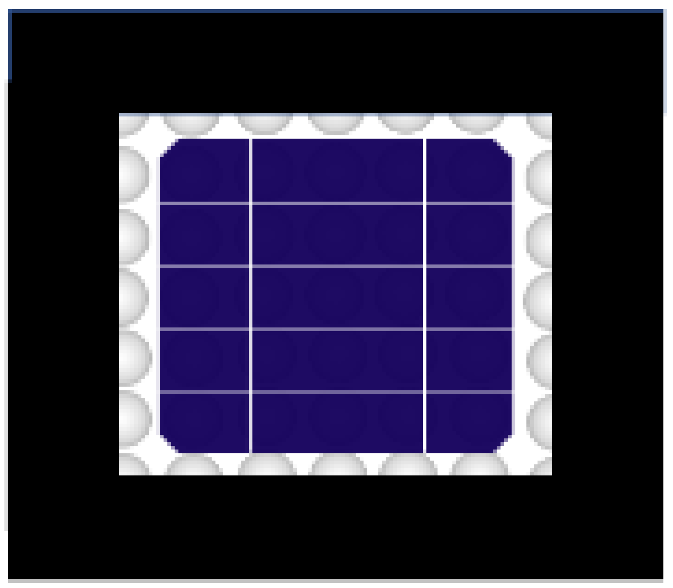 | 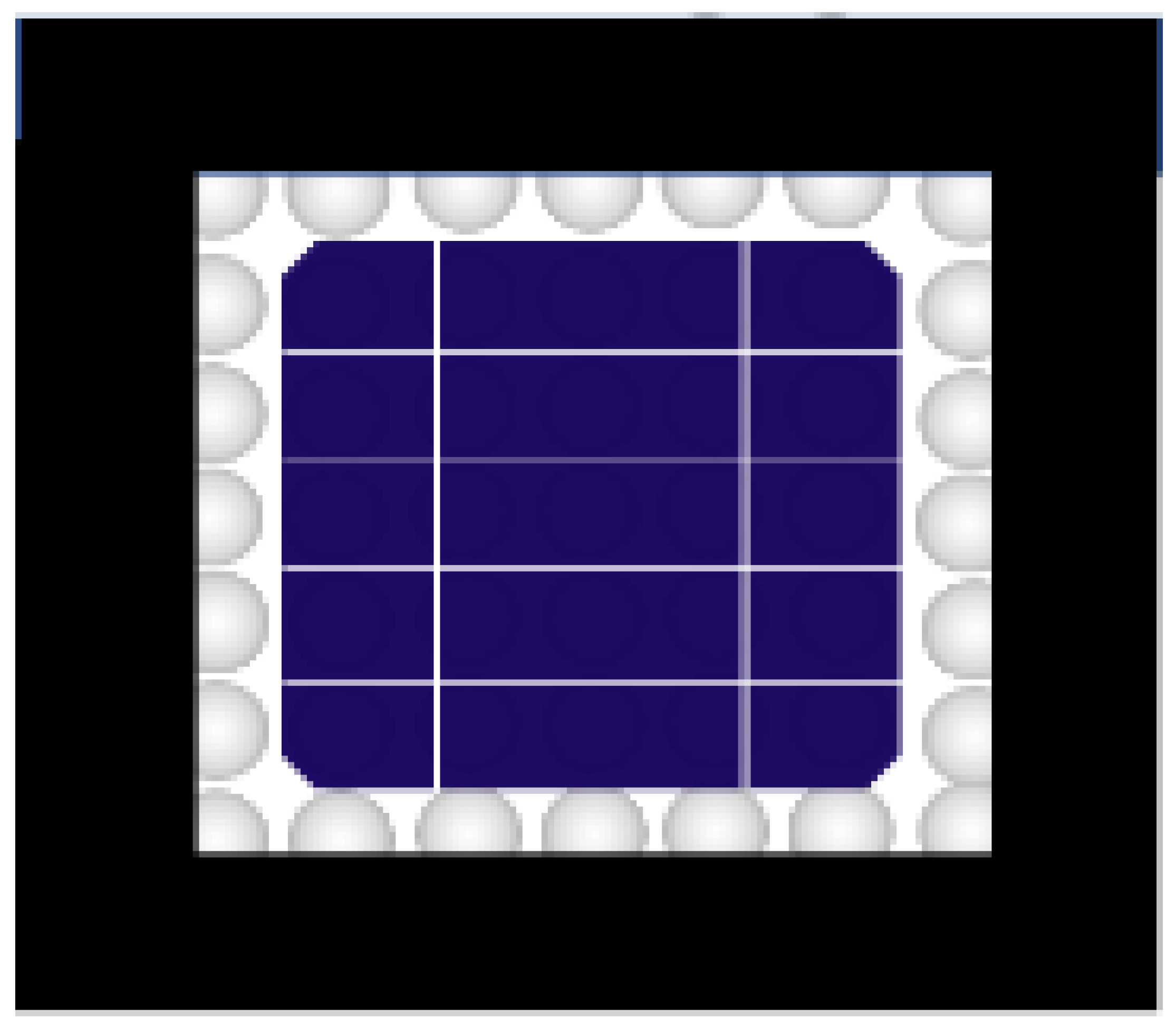 | 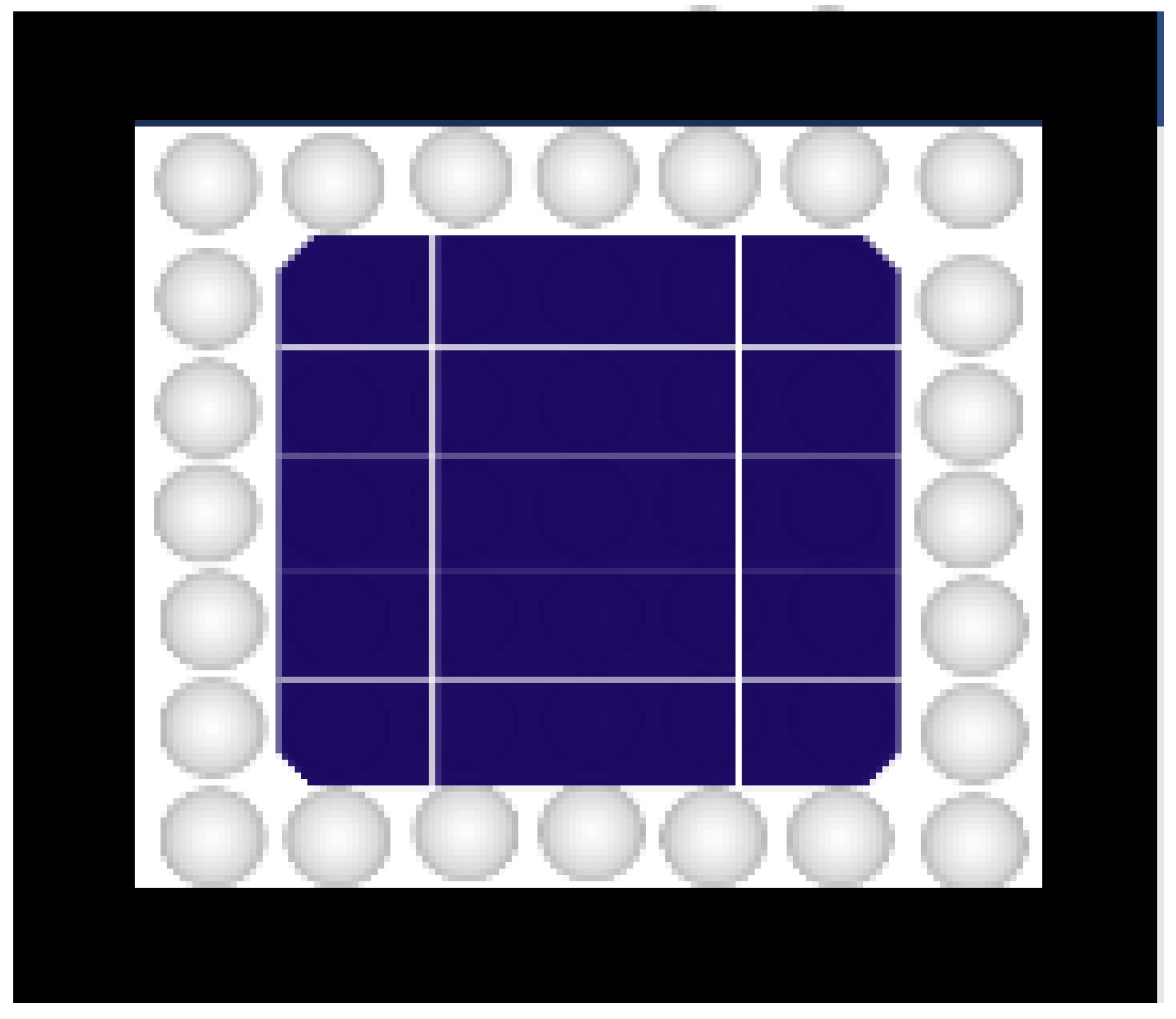 | 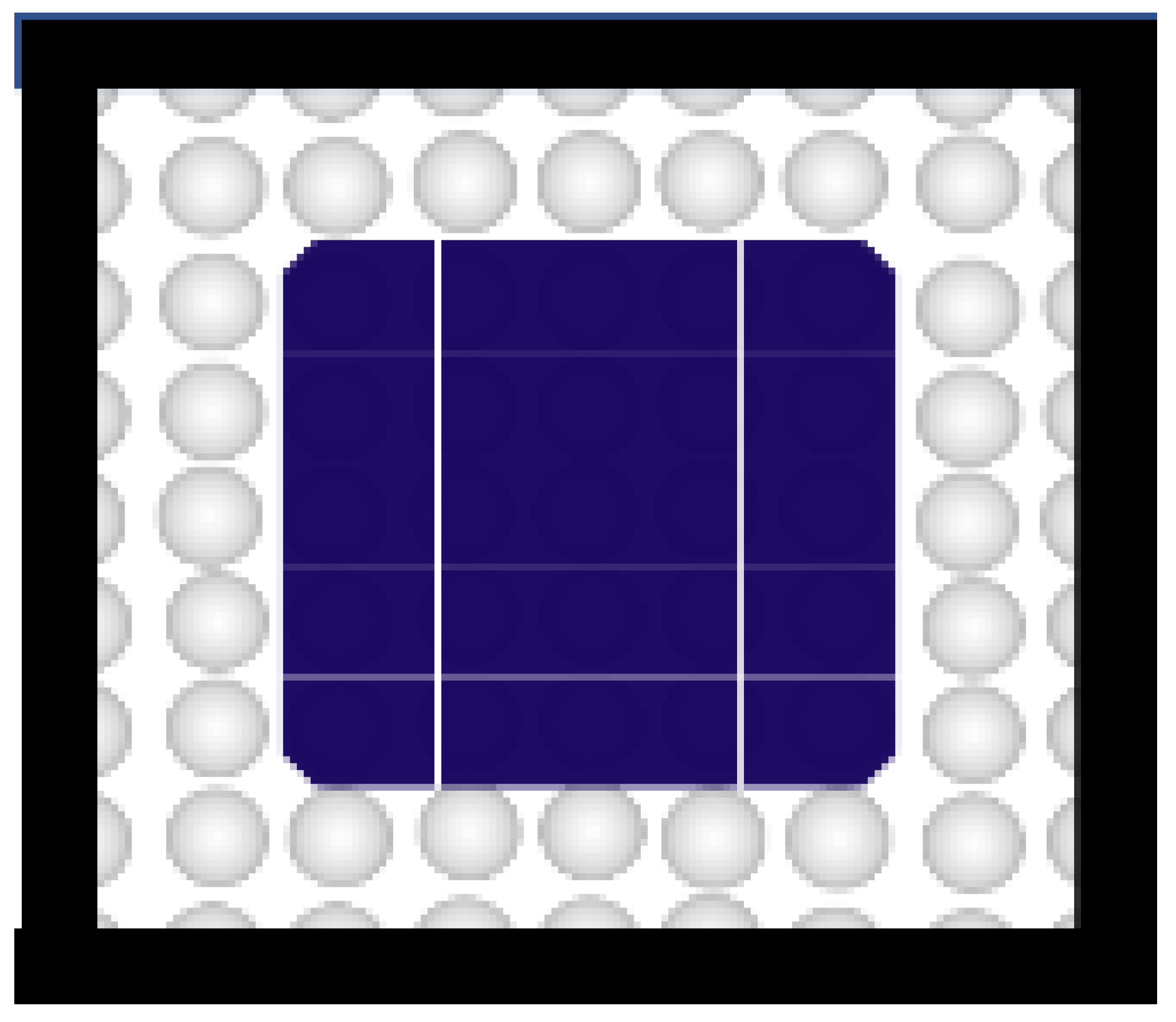 |
| ACell (mm2) | 2500 | 2500 | 2500 | 2500 |
| AGap (mm2) | 525 | 806 | 1100 | 1406 |
| AGap/ACell+AGap (%) | 17.3% | 24.3% | 30.5% | 36% |
Disclaimer/Publisher’s Note: The statements, opinions and data contained in all publications are solely those of the individual author(s) and contributor(s) and not of MDPI and/or the editor(s). MDPI and/or the editor(s) disclaim responsibility for any injury to people or property resulting from any ideas, methods, instructions or products referred to in the content. |
© 2024 by the authors. Licensee MDPI, Basel, Switzerland. This article is an open access article distributed under the terms and conditions of the Creative Commons Attribution (CC BY) license (https://creativecommons.org/licenses/by/4.0/).
Share and Cite
Song, H.-J.; Lee, D.; Kim, C.; Na, J.-H. Improved Performance of Bifacial Photovoltaic Modules with Low-Temperature Processed Textured Rear Reflector. Appl. Sci. 2024, 14, 8718. https://doi.org/10.3390/app14198718
Song H-J, Lee D, Kim C, Na J-H. Improved Performance of Bifacial Photovoltaic Modules with Low-Temperature Processed Textured Rear Reflector. Applied Sciences. 2024; 14(19):8718. https://doi.org/10.3390/app14198718
Chicago/Turabian StyleSong, Hyung-Jun, Deukgwang Lee, Chungil Kim, and Jun-Hee Na. 2024. "Improved Performance of Bifacial Photovoltaic Modules with Low-Temperature Processed Textured Rear Reflector" Applied Sciences 14, no. 19: 8718. https://doi.org/10.3390/app14198718