Research on Disaster Prevention and Control Technology for Directional Hydraulic Fracturing and Roof Plate Unloading

 , ,
, ,
Abstract
1. Introduction
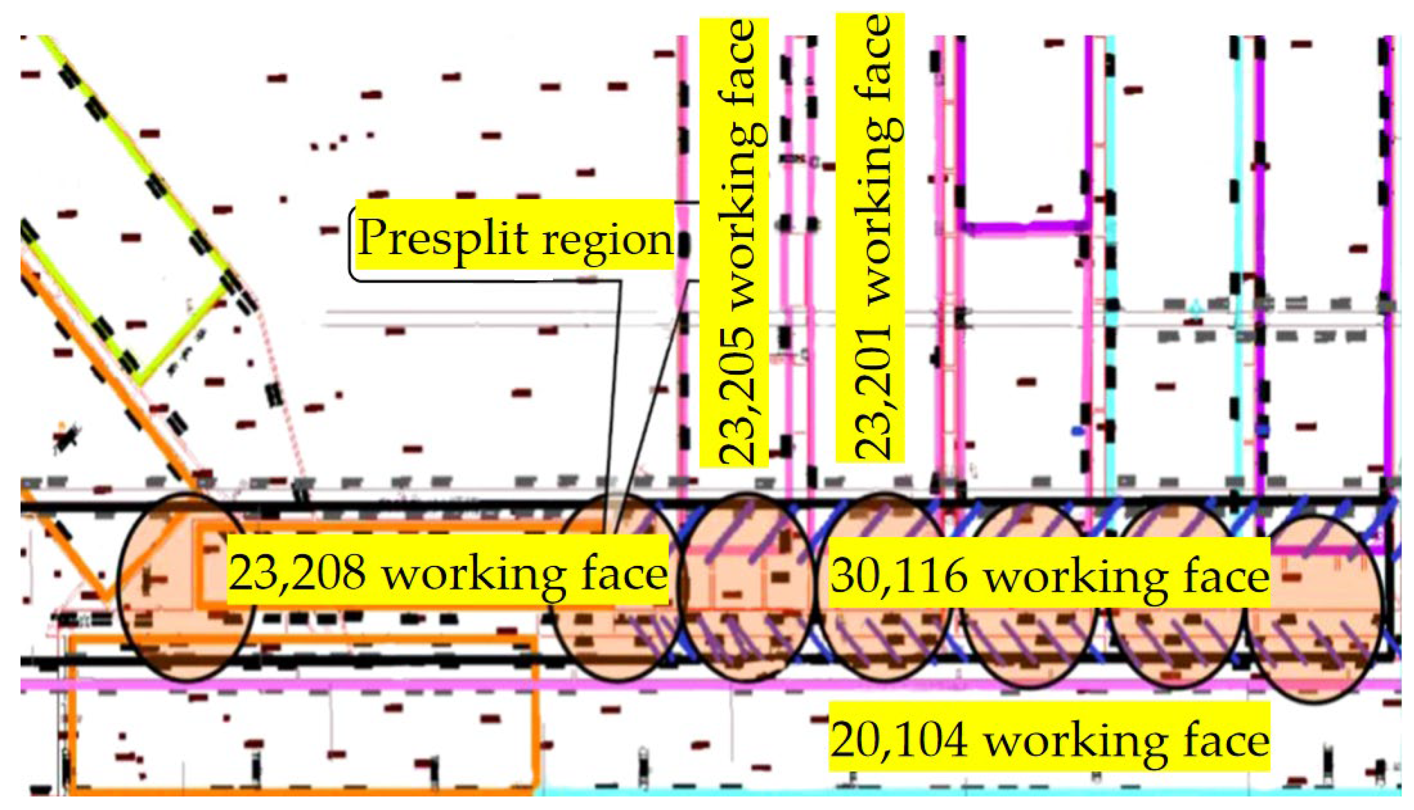
2. Overview of the Mine and Workings
3. Mechanism Analysis of Directional Hydraulic Fracturing Unloading and Determination of Key Parameters
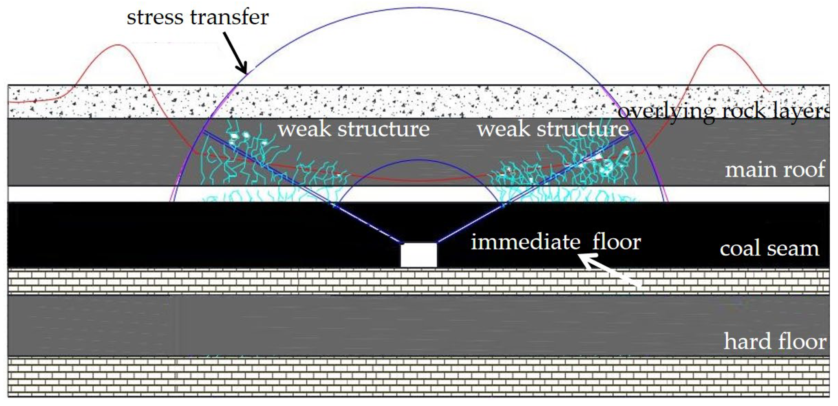
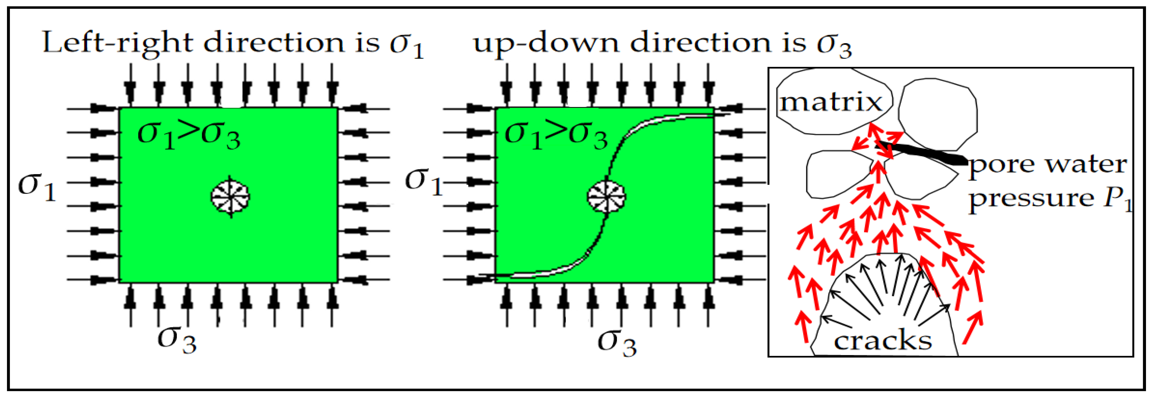
3.1. Mechanism Analysis of Unloading Mechanism in Directional Hydraulic Fracturing
3.2. Directional Hydraulic Fracturing Process Design Process and Steps
- Determine the range of fracturing Lh according to the desired damage variable D;
- Given an initial fracturing displacement Q and fracturing time T, calculate the radius of fracture propagation R;
- Based on the radius of fracture propagation R, determine the spacing of the drilled holes d;
- Based on the spacing of the drilled holes d and the range of fracturing Lh, the number of drilled holes m can be determined, and the arrangement of the boreholes can be determined by m;
- Knowing the damage variable D and the number of drilled holes m, the number of fracturing segments n for each borehole can be calculated. Through the fracturing range Lh and the number of fracturing segments n, the fracturing spacing d0 can be calculated, and since the number of fracturing segments n must be an integer, accordingly, the fracturing time T can be adjusted by feedback until n is an integer ≥1.
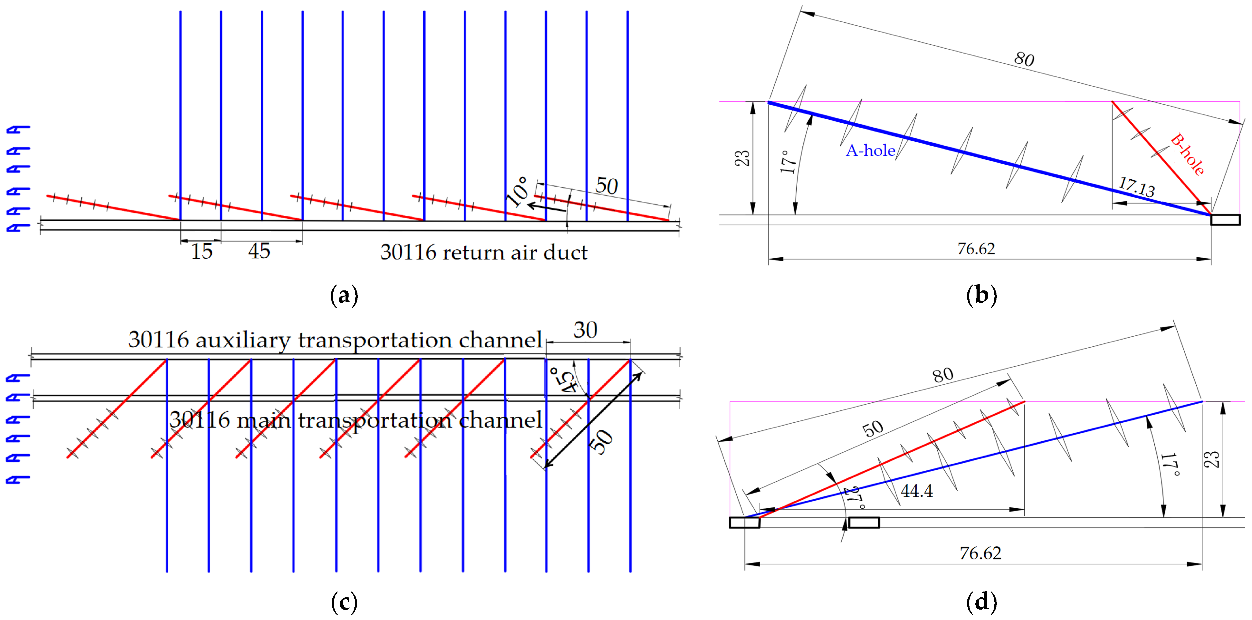
3.3. Determination of Key Parameters for Directional Hydraulic Fracturing
- Determination of the extent of the fracturing section
- 2.
- Determination of drilling angle
- 3.
- Determination of drilling spacing
- 4.
- Determination of the number of fracturing segments per borehole
- Pre-fracture pressure: Controlled at 10~25 MPa.
- Pre-fracture penetration radius: 15 m.
- Fracturing time of single hole: 30 min.
- Number of fracturing segments per borehole: 5~6.
- Fracturing method: Transverse fracture.
- The ratio of coal rock active water was determined according to the actual water quality coefficient of the coal seam at the site.
- Pre-cracking volume: 0.7 m3 for single hole, 1~2 m3 cumulative.
- Pre-cracking flow rate: according to experience, it should be 0.7~2.0 m3/h for dynamic pressure pre-cracking.
4. Directional Hydraulic Fracturing Fracture Evolution Law
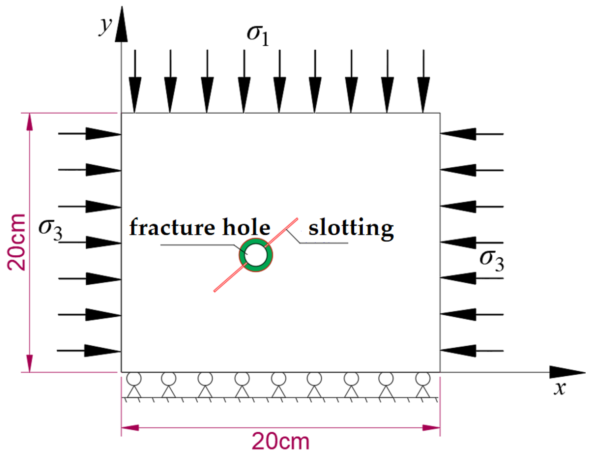
4.1. Establishment of RFPA 3D Numerical Simulation
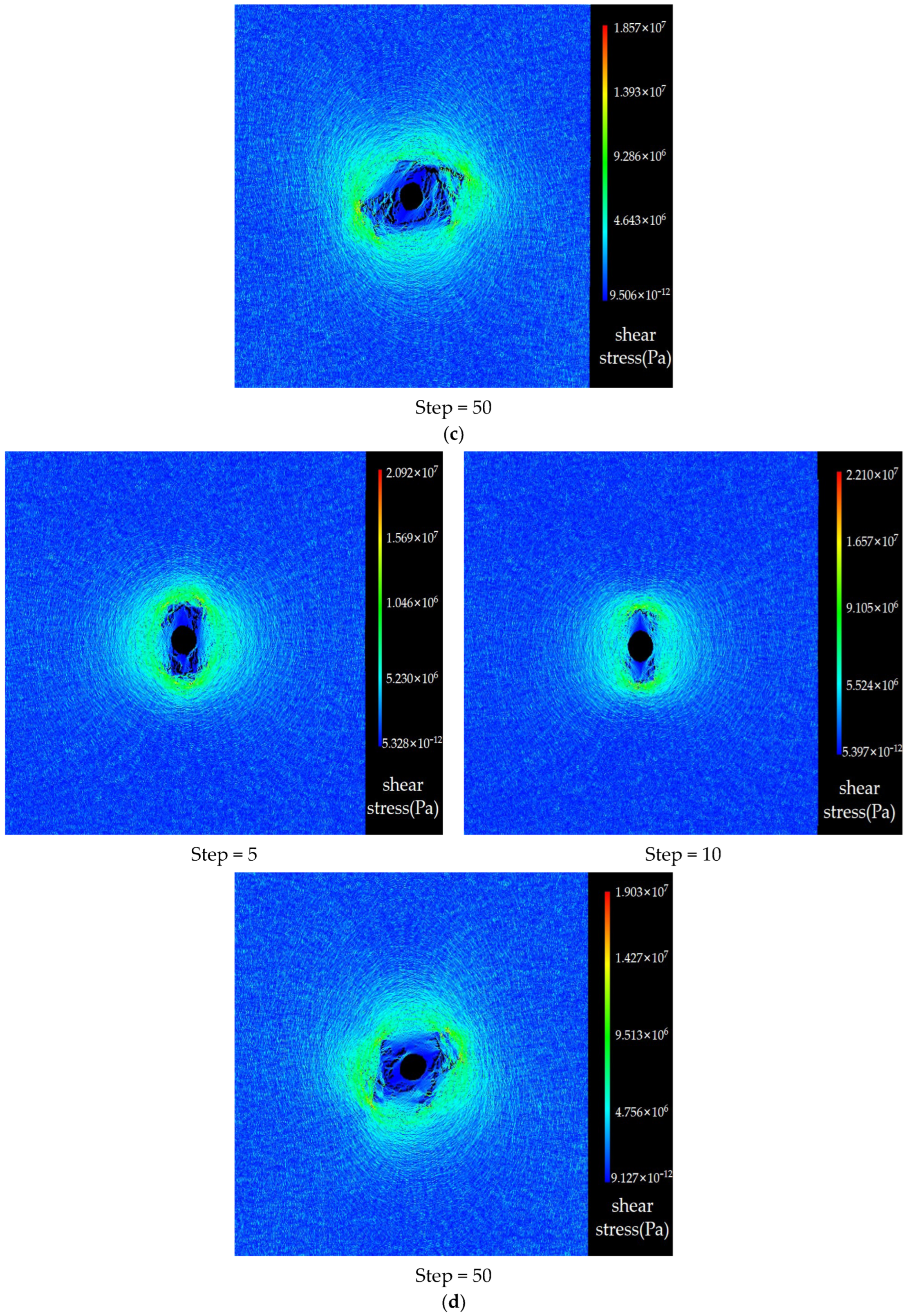
4.2. Factors Affecting Crack Initiation and Expansion
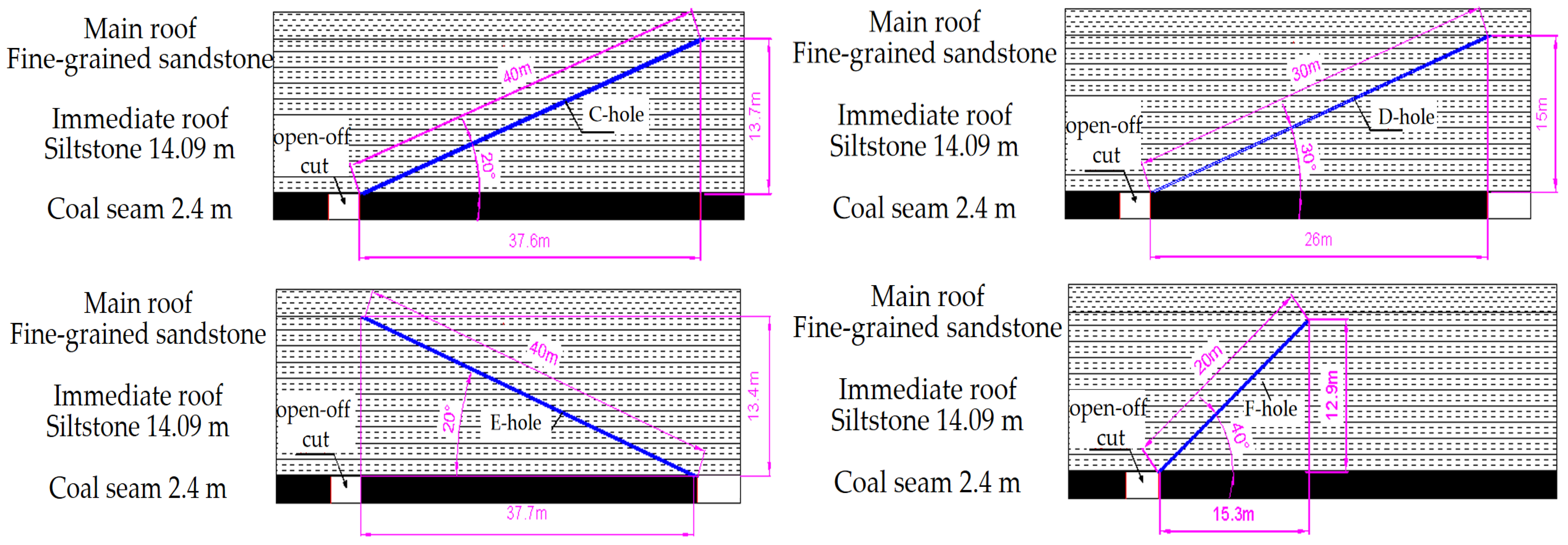
4.2.1. Effect of Different Angles on Crack Initiation and Expansion
- 0° prefabricated crack
- 2.
- 30° prefabricated crack
- 3.
- 60° prefabricated crack
- 4.
- 90° prefabricated crack
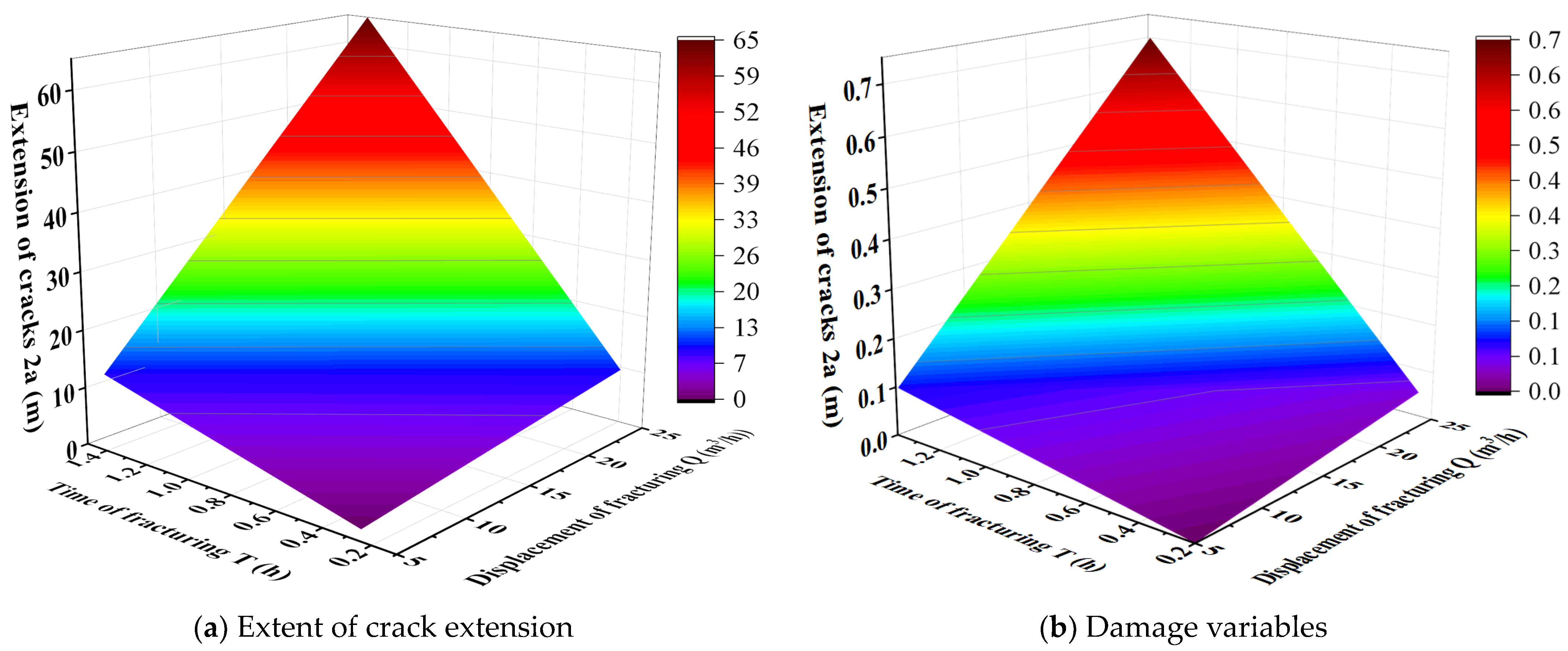
4.2.2. Effect of Fracturing Displacement on Fracture Initiation and Expansion
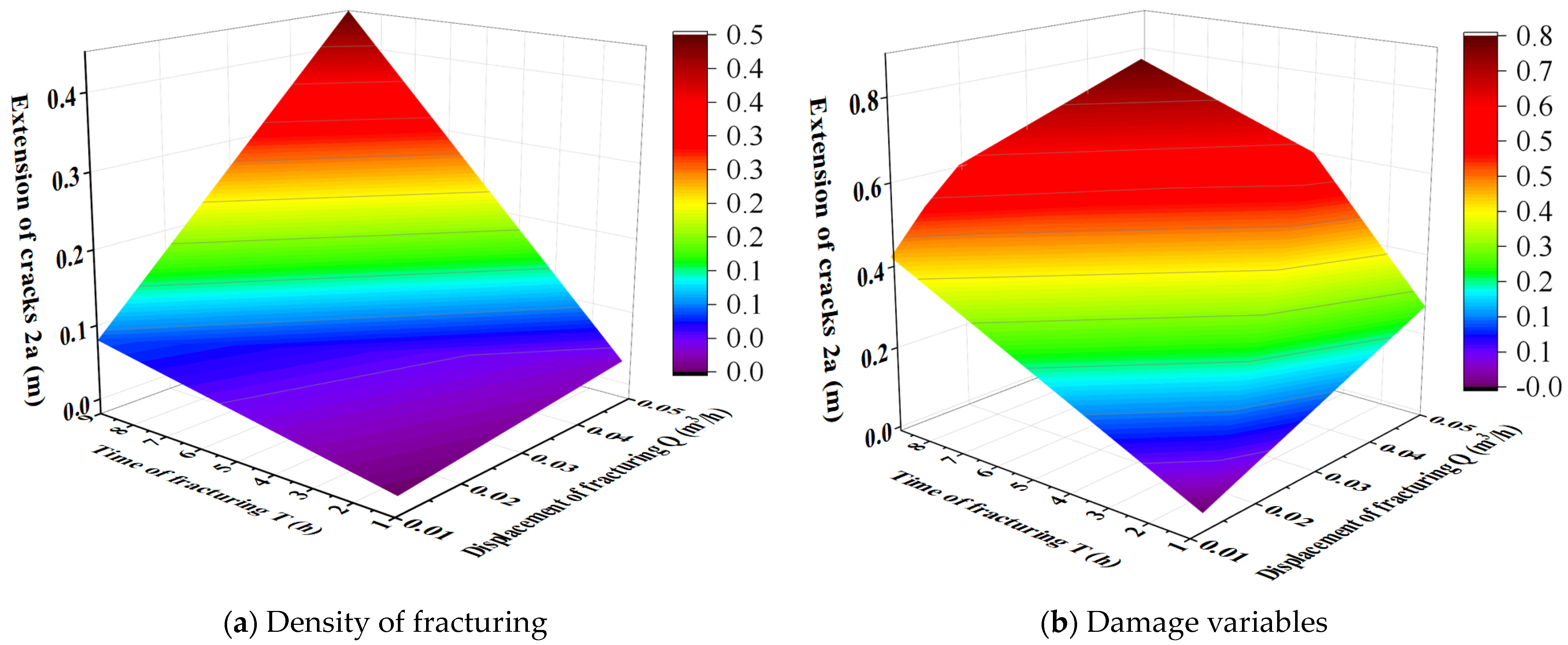
4.2.3. Effect of Fracturing Segment Spacing on Fracture Initiation and Expansion
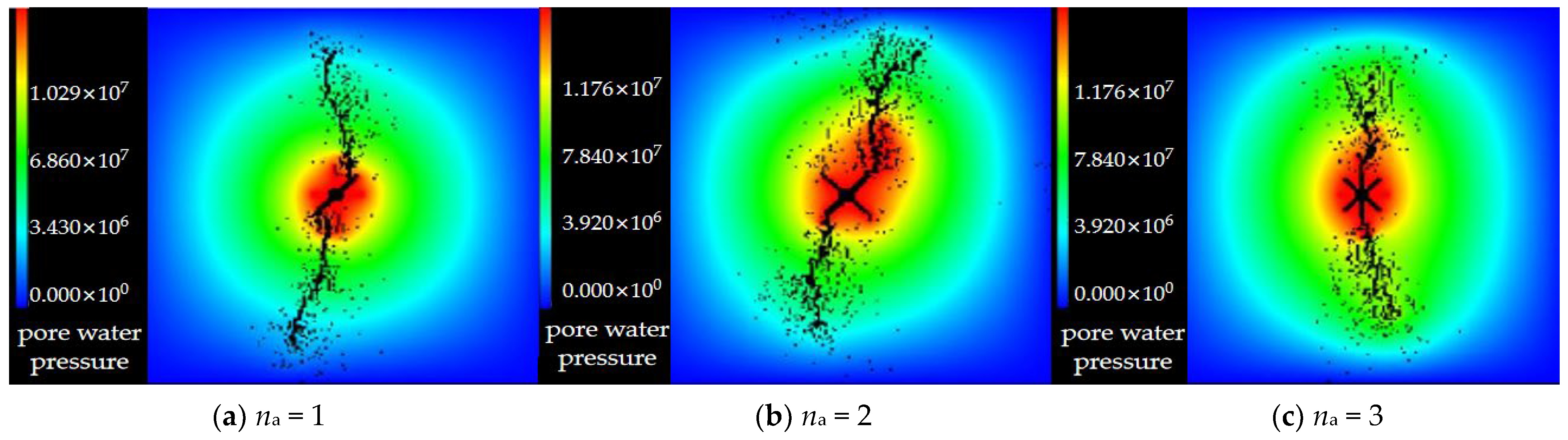
4.2.4. Effect of Fracture Number on Fracture Initiation and Propagation
5. Field Application of Directional Hydraulic Fracturing Unloading Technology
5.1. Implementation Program Design
- 30,116 working face
- 2.
- 30,119 working face
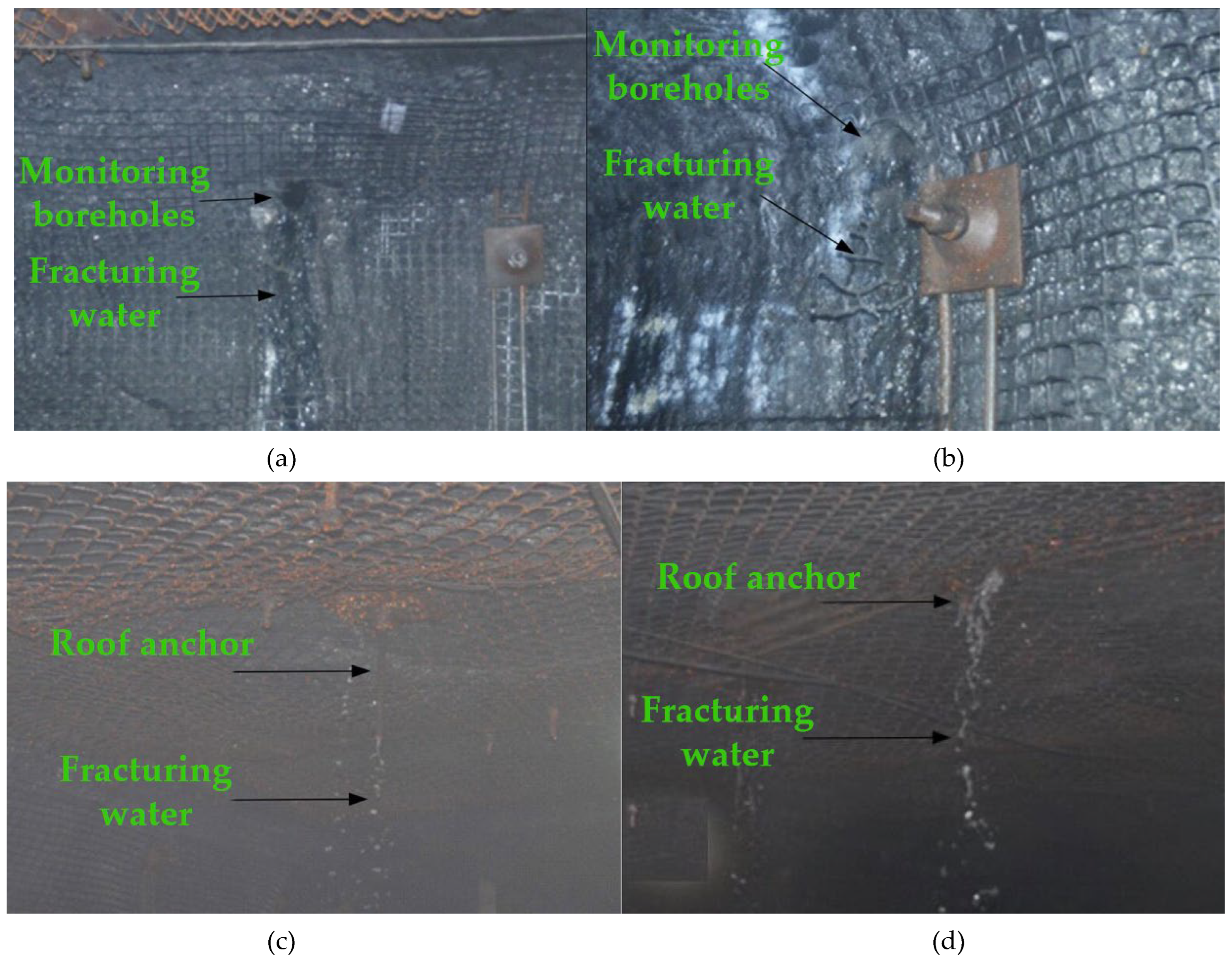
5.2. Analysis of Fracturing and Pressure Relief Effects
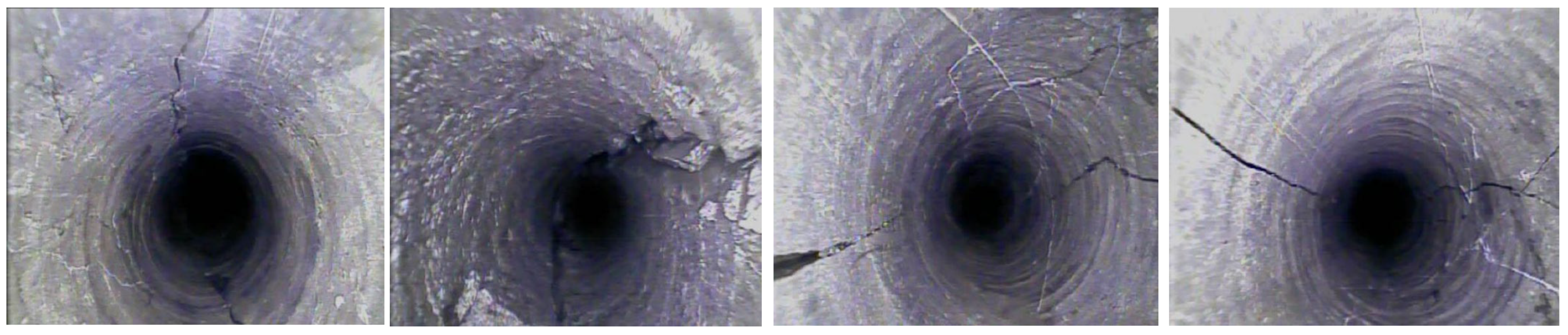
- Fracturing effect analysis
- 2.
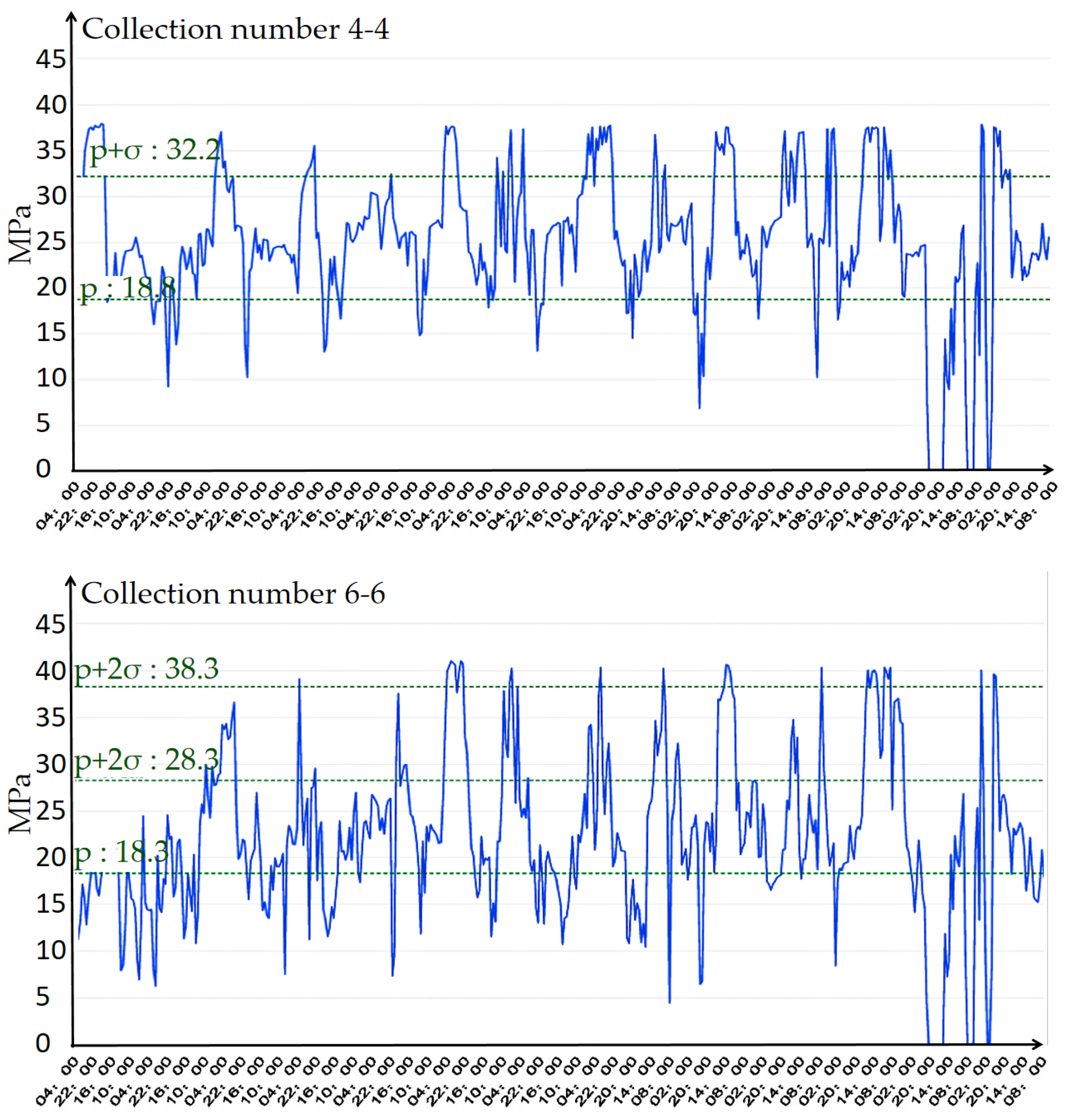
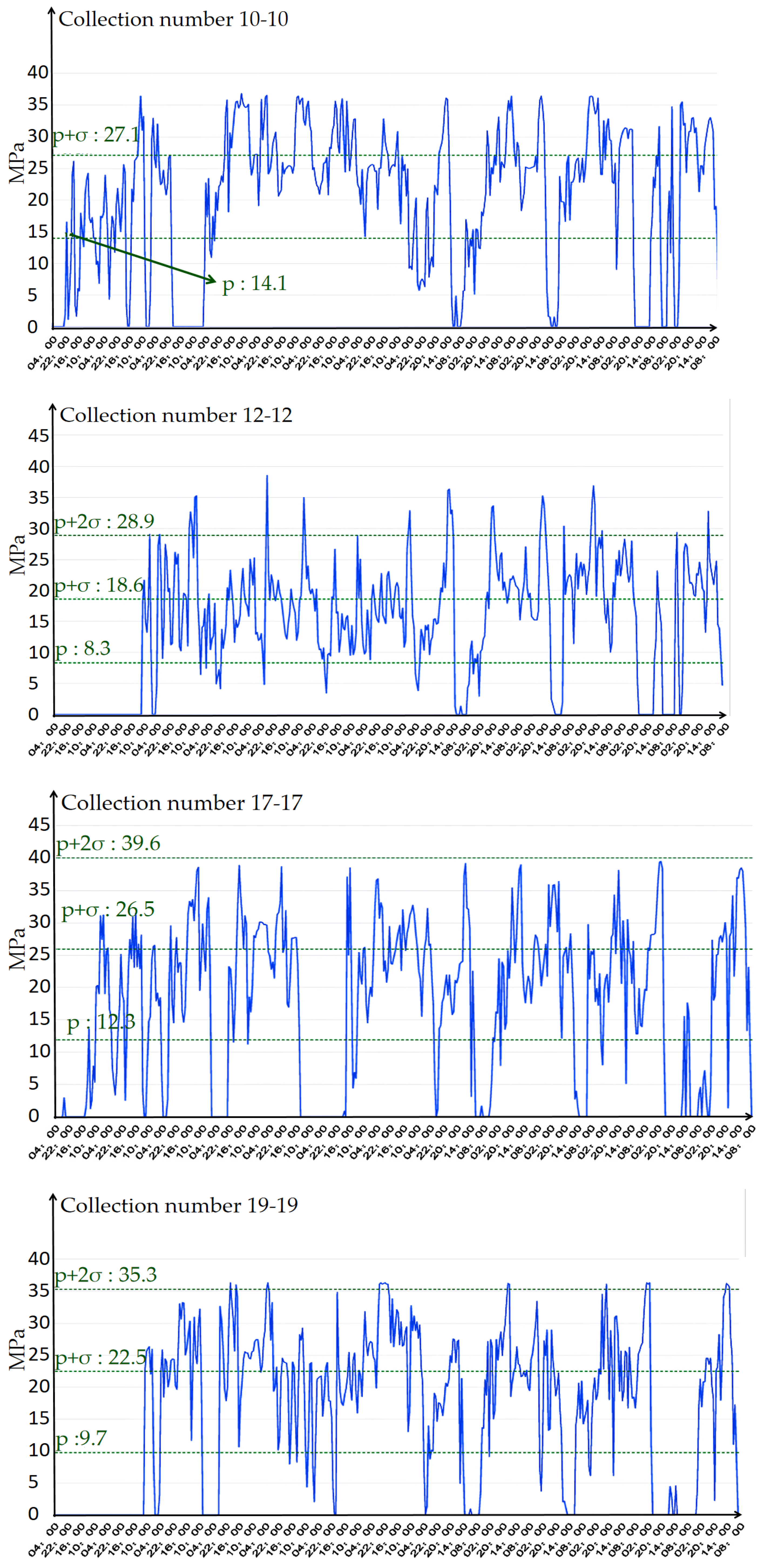
- Analysis after pressure relief
6. Conclusions
- The key parameters of the 3−1 coal seam were determined based on the analysis of the mechanism of unloading pressure of directional hydraulic fracturing.
- Various angles, fracture displacements, segment spacings, and fracture numbers were modeled using RFPA 3D numerical simulation software. The influence of these factors on hydraulic fracture initiation and propagation was comparatively analyzed, leading to the formulation of the directional hydraulic fracture evolution law. The results indicated that the extent of damage to the weak structural body of the coal rock is dependent on the hydraulic fracturing crack parameters. Variations in hydraulic fracturing process parameters lead to differing fracture morphologies, damage variables, and corresponding stress transfer effects in the weak structural body. Additionally, the hydraulic fracturing process parameters combined with damage variables determined the use of transverse fractures for directional fracturing in the 30,116 and 30,119 working faces of the 3−1 coal seam at the Yanghuopan Mine. The drill holes were spaced 15 m apart, with 5 to 6 fracturing segments per hole, a single-hole fracturing duration of 30 minutes, and pre-fracturing pressure controlled between 10 and 25 MPa.
- The on-site monitoring results show that under the effect of directional hydraulic pressure on the rock body of the roof slab of the 30,116 general mining face (under the effect of directional hydraulic pressure on the roof slab of the 30,119 general mining face with open cut eyes), the fracture network expansion reached the expected effect. The fracture network developed well, effectively releasing concentrated stress in the rock body. During mining operations, the bracket pressure remained stable and exhibited clear periodicity, achieving the desired effect of pressure relief to prevent and control roof-related hazards.
Author Contributions
Funding
Institutional Review Board Statement
Informed Consent Statement
Data Availability Statement
Acknowledgments
Conflicts of Interest
Appendix A

| Variable | Meaning |
|---|---|
| D | Damage variable |
| Lh | Range of fracturing |
| Q | Initial fracturing displacement |
| T | Fracturing time |
| R | Radius of fracture propagation |
| d | Spacing of the drilled holes |
| d0 | Fracturing spacing |
| m | Number of drilled holes |
| n | Number of fracturing segments |
| xt, xtd | Range of influence of the support stress |
| σ3 | Minimum principal stress in the initial state |
| σ3a, σ3b | Minimum principal stress in a given state |
| φ | Angle of internal friction |
| M | Material parameters |
| C | Cohesion of the soil |
| Da, Db | Location-specific damage variables |
| β | Inclination of the crack |
| K, Kγγ | Soil permeability coefficient |
| V(x) | Displacement function, indicating the displacement at position (x) |
| E | Modulus of elasticity of the coal rock |
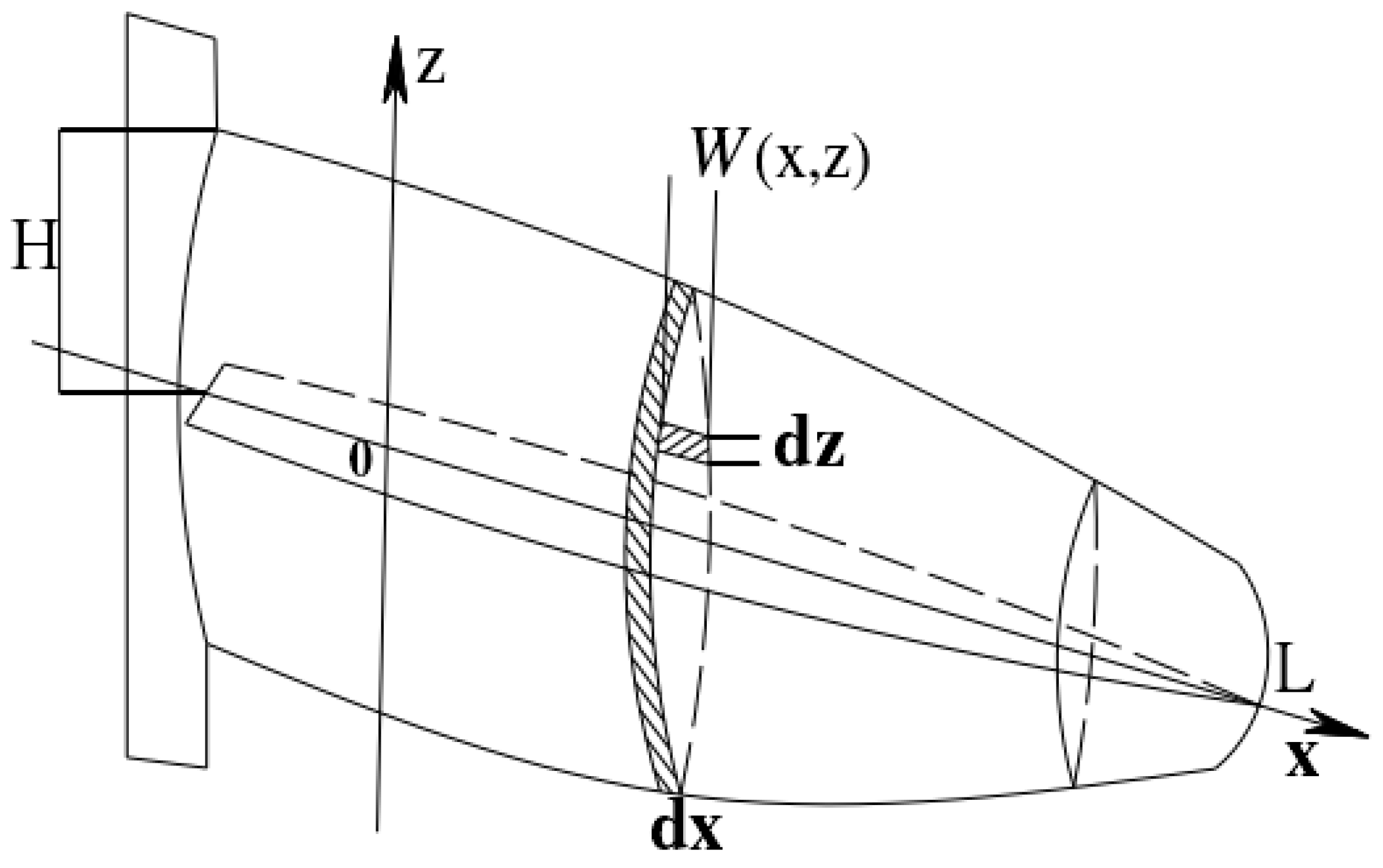
| L | Fracture depth |
| H | Length of the crack |
| σ | In-seam hydraulic pressure |
| σx | Liquid pressure in the seam in the x-axis direction |
| x | Horizontal distance |
| z | Distance in the vertical direction |
| W(x,z) | Slit width of the fractured fissure at a specific location (x,z) |
| t | Fracturing time |
| a | Radius of the crack |
| B | Constants of the material |
| τeff | Effective shear stress |
| ϕ | Porosity of the substrate |
| V | Volume of fractured area |
| σeq | Constant force |
| σm | Average stress |
| ν | Velocity of fluid percolation in the matrix |
References
- Liu, Y. Research on the Formation and Development of Safety Concept Based on the Technological Change of Mining and Safety Protection in China. Ph.D. Thesis, Central South University, Changsha, China, 2009. [Google Scholar]
- Jin, Z. Study on Overburden Movement Law and Surrounding Rock Deformation Mechanism in Closse-Distance Coal Seam Mining of Shaping Mine. Ph.D. Thesis, China University of Mining and Technology, Beijing, China, 2018. [Google Scholar]
- Jia, S. Research on Mine Pressure Prevention and Control Technology for Mining Lower Coal Seam through Concentrated Coal Pillar in Close Distance at Shangwan Coal Mine. Bachelor’s Thesis, Xi’an University of Science and Technology, Xi’an, China, 2020. [Google Scholar] [CrossRef]
- Zhang, C. Research on the collapse and transportation law of overburden rock in upstream mining of close coal seam group. Coal Sci. Technol. 2018, 46, 1–7. [Google Scholar] [CrossRef]
- Wang, W.; Gong, Z. Deformation law and control of surrounding rock in dynamic pressure roadway mining under coal pillar of close seam group. Coal Sci. Technol. 2022, 50, 143–152. [Google Scholar] [CrossRef]
- Yang, T.; Yan, Y.; Zhang, J.; Lin, H.; He, Y.; Zhang, Y.; Gao, S. Study on Synergistic Water-Resisting Stability of Upper and Lower Soil Layers and Bedrock Layers in Shallow Coal Seam Group. Coal Sci. Technol. 2023, 51, 234–242. [Google Scholar] [CrossRef]
- Huang, Q.; Li, K.; Cao, J. Analysis of Mine Pressure Characteristics and Roof Structure in Working Face under Shallow Buried Close-Distance Goaf. Shaanxi Coal 2021, 40, 12–17. [Google Scholar]
- Huang, Q.; Dum, J.; Hou, E.; Yang, F. Study on Development Law and Formation Mechanism of Overburden and Surface Cracks in Shallow Coal Seam Group. J. Min. Saf. Eng. 2019, 36, 7–15. [Google Scholar] [CrossRef]
- Wang, C.; Zhang, X.; Wang, H. Mine Pressure Manifestation Law of Shallow Buried Close Distance Coal Seam Passing Through Upper Goaf and Coal Pillar. Coal Mine Saf. 2016, 47, 55–58. [Google Scholar] [CrossRef]
- Zhang, J.; He, Y.; Wang, X.; Feng, C.; Yang, T.; Kang, X.; Li, H. Analysis and Research on Overburden Failure Law of Repeated Mining in Shallow Buried Close Distance Coal Seam Group. Min. Res. Dev. 2022, 42, 60–64. [Google Scholar] [CrossRef]
- Zhang, J.; He, Y. Study on Fracture Evolution Law and Combined Bearing Structure Load of Shallow Coal Seam Group. Coal Sci. Technol. 2023, 51, 65–76. [Google Scholar] [CrossRef]
- Yang, T.; Sun, J.; Zhang, J.; Lin, H.; Yan, Y.; He, Y.; Zhang, Y.; Sun, J. Optimization Study on Coal Pillar Width Setting in Shanyang Coal Mine Area. Min. Res. Dev. 2024, 44, 7–14. [Google Scholar] [CrossRef]
- Keshavarz, A.; Badalyan, A.; Johnson, R.J., Jr.; Bedrikovetsky, P. Productivity enhancement by stimulation of natural fractures around a hydraulic fracture using micro-sized proppant placement. J. Nat. Gas Sci. Eng. 2016, 33, 1010–1024. [Google Scholar] [CrossRef]
- Zhu, W. Research on Key Layer Structure Instability Mechanism of Repeated Mining in Shallow Buried Close Distance Coal Seam. Ph.D. Thesis, China University of Mining and Technology, Xuzhou, China, 2010. [Google Scholar]
- Gu, S.; Chen, P.; Wang, J.; Wang, H. Field Measurement Study on Mine Pressure Manifestation Law of Coal Seam Mining under Goaf. Coal Eng. 2013, 45, 64–67. [Google Scholar]
- Liu, C.; Liu, J. Stress Transfer Principle and Application of Weak Structure in Coal and Rock Mass Fracturing. J. Min. Saf. Eng. 2022, 39, 359–369. [Google Scholar] [CrossRef]
- Liu, J. Research on Stress Field Change Mechanism and Control of Artificially Fractured Coal and Rock Mass. Ph.D. Thesis, China University of Mining and Technology, Xuzhou, China, 2020. [Google Scholar] [CrossRef]
- Shevtsova, A.; Stanchits, S.; Bobrova, M.; Filev, E.; Borodin, S.; Stukachev, V.; Magadova, L. Laboratory Study of the Influence of Fluid Rheology on the Characteristics of Created Hydraulic Fracture. Appl. Sci. 2022, 15, 3858. [Google Scholar] [CrossRef]
- Chang, B.; Zhao, Z.; Yang, W.; Yang, X.; Yang, H.; Zheng, K.; Kong, L. Technology and Application of Ultra-long Borehole Directional Three-dimensional Hydraulic Fracturing for Hard and Thick Roof of Extra-thick Gently Inclined Coal Seam. China Min. Mag. 2023, 32, 160–167. [Google Scholar]


| Parameters | Mean Value of Modulus of Elasticity/MPa | Degree of Homogeneity/m | Friction Angle/(°) | Average Compressive Strength/MPa | Poisson’s Ratio |
|---|---|---|---|---|---|
| Parameter value | 9600 | 3 | 37 | 30 | 0.25 |
| Parameters | Permeability Coefficient/m·d−1 | Pore Water Pressure/MPa | Permeability Coefficient After Rupture | Pore Water Pressure Coefficient | Loading Method |
| Parameter value | 0.001 | 1.0 | 10 | 0.1 | Stress loading |
Disclaimer/Publisher’s Note: The statements, opinions and data contained in all publications are solely those of the individual author(s) and contributor(s) and not of MDPI and/or the editor(s). MDPI and/or the editor(s) disclaim responsibility for any injury to people or property resulting from any ideas, methods, instructions or products referred to in the content. |
© 2024 by the authors. Licensee MDPI, Basel, Switzerland. This article is an open access article distributed under the terms and conditions of the Creative Commons Attribution (CC BY) license (https://creativecommons.org/licenses/by/4.0/).
Share and Cite
Liu, D.; Deng, J.; Yang, T.; Zhang, J.; Lin, H.; Liu, H.; Sun, J.; Zhang, Y. Research on Disaster Prevention and Control Technology for Directional Hydraulic Fracturing and Roof Plate Unloading. Appl. Sci. 2024, 14, 8733. https://doi.org/10.3390/app14198733
Liu D, Deng J, Yang T, Zhang J, Lin H, Liu H, Sun J, Zhang Y. Research on Disaster Prevention and Control Technology for Directional Hydraulic Fracturing and Roof Plate Unloading. Applied Sciences. 2024; 14(19):8733. https://doi.org/10.3390/app14198733
Chicago/Turabian StyleLiu, Dong, Jiayue Deng, Tao Yang, Jie Zhang, Haifei Lin, Hui Liu, Jiarui Sun, and Yiming Zhang. 2024. "Research on Disaster Prevention and Control Technology for Directional Hydraulic Fracturing and Roof Plate Unloading" Applied Sciences 14, no. 19: 8733. https://doi.org/10.3390/app14198733
APA StyleLiu, D., Deng, J., Yang, T., Zhang, J., Lin, H., Liu, H., Sun, J., & Zhang, Y. (2024). Research on Disaster Prevention and Control Technology for Directional Hydraulic Fracturing and Roof Plate Unloading. Applied Sciences, 14(19), 8733. https://doi.org/10.3390/app14198733