Article

Subsidence Prediction Method Based on Elastic Foundation Beam and Equivalent Mining Height Theory and Its Application

1
School of Mechanics and Civil Engineering, China University of Mining and Technology, Xuzhou 221116, China
2
State Key Laboratory of Intelligent Construction and Healthy Operation and Maintenance of Deep Underground Engineering, China University of Mining and Technology, Xuzhou 221116, China
3
Leicester International Institute, Dalian University of Technology, Panjin 124221, China
*
Author to whom correspondence should be addressed.
Appl. Sci. 2024, 14(19), 8766; https://doi.org/10.3390/app14198766 (registering DOI)
Submission received: 22 August 2024 / Revised: 23 September 2024 / Accepted: 25 September 2024 / Published: 28 September 2024
(This article belongs to the Section Mechanical Engineering)

Abstract

:
Grouting technology in overburden separation is recognized as an effective method to prevent surface subsidence and reuse solid waste. This study used mechanical analysis to explore deflection characteristics of key strata and accurately predict and control surface subsidence. Conceptualizing the coal–rock mass beneath the key strata as an elastic foundation, we developed a method to calculate the elastic foundation coefficients for various regions and established an equation for key strata deflection, validated through discrete element numerical simulations. This simulation also examined subsidence behavior under different grout injection–extraction ratios. Additionally, combining the equivalent mining height theory with the probability integral method, we formulated a predictive model for surface subsidence during grouting. Applied to the 8006 working face of the Wuyang Coal Mine, this model was supported by numerical simulations and field data, which showed a maximum surface subsidence of 546 mm at a 33% injection–extraction ratio, closely matching the theoretical value of 557 mm and demonstrating a nominal error of 2%. Post-grouting, the surface tilt was reduced to below 3 mm/m, meeting regulatory standards and eliminating the need for ongoing surface structure maintenance. These results confirm the model’s effectiveness in forecasting and controlling surface subsidence with grouting. The study can provide a basis for determining the grouting injection–extraction ratios and evaluating the effectiveness of surface subsidence control in grouting into overburden separation projects.

1. Introduction

The extraction of coal mines is known to precipitate surface subsidence, which can inflict substantial damage on surface infrastructures and aquatic systems [1,2,3]. Reports indicate that approximately 14 billion tons of coal lie beneath structures such as buildings, railways, and water bodies within China [4]. Traditional mining methods exacerbate ground subsidence, posing a significant threat to the structural integrity of surface constructions and railways [5]. Furthermore, during the process of longwall mining, it is common for horizontal separation to manifest between the key strata and the underlying rock layers of the working face [6]. This separation often leads to the accumulation of substantial quantities of groundwater or gas, adversely impacting mining safety [7]. In addressing these pervasive challenges, researchers have explored and refined various filling techniques. Notably, the method of grouting into overburden separation has emerged as a favored solution due to its simplicity, cost-effectiveness, and minimal interference with ongoing mining operations [8].
Grouting into overburden separation represents an innovative technique for controlling surface subsidence. The fundamental principle involves pumping a slurry, prepared at the surface, into the overburden separation via a grouting borehole. This filling slurry then supports the key strata, effectively mitigating the transmission of overburden movement to the surface. Fan et al. [9] introduced a method for identifying the location of overburden separation and calculating the aperture size needed for effective separation. The practicality of these methods was substantiated through the use of a multi-point extensometer. Furthermore, Xuan et al. [10] developed the concept of isolated overburden grout injection, which constructs a supportive structure consisting of a sufficiently compacted area, an isolated coal pillar, and key strata. This structure is designed to significantly diminish surface subsidence. Xuan et al. [11] developed a method to calculate the optimal injection–extraction ratio, taking into account the characteristics of the main injection horizon and the geological features of the surrounding strata. This method aids in refining the design of the injection process. Li et al. [12] conducted a case study on the 7221 working face in Huaibei, where isolated overburden grout injection was utilized. They classified and analyzed the influence of various grouting parameters on controlling surface subsidence. Furthermore, Zhang et al. [13] undertook experimental research on the compression properties of slurry used for grouting into overburden separation and introduced a formula to determine the maximum permissible use of fly ash in the grouting mixture. As a technique to stabilize key strata, the structural integrity and movement of these strata are critical in influencing surface subsidence. To address the deflection of key strata, three primary mechanical models are considered: a cantilever or fixed support [14,15], an elastic thin plate [16,17,18], or an elastic foundation beam [19,20]. Of these, the elastic foundation beam model, capable of simulating complex boundary conditions, is most frequently employed to analyze the deflection of rock layers under filling conditions [21]. For predicting subsidence, the probability integration method is commonly used [22]. However, traditional applications of this method are limited to mining rectangular working faces with uniform mining heights. By incorporating the concept of equivalent mining height, it becomes possible to apply the probability integration method to predict surface subsidence in solid filling conditions within the goaf, adapting it to varying working face configurations [23].
Numerous engineering practices have demonstrated the effective control of surface subsidence through grouting into overburden separation projects, and the subsidence control of the key strata is critical to the effect of the grouting. However, previous studies have overlooked factors influencing the control effectiveness of grout filling on surface subsidence and only provided a qualitative analysis of individual parameters [24]. Additionally, surface subsidence prediction has neglected the consideration of physical and mechanical properties as well as movement processes of overlying strata, treating them (including key layers) as homogeneous granular media, resulting in significant errors in practical applications. Furthermore, there is a lack of accurate numerical simulation methods specifically designed for predicting surface subsidence caused by grouting into overburden separation. To address these challenges, this paper introduces a mechanical model for key strata deflection and a predictive model for surface subsidence under grouting into overburden separation conditions, grounded in the theories of elastic foundation beams and equivalent mining height. Moreover, we developed a numerical simulation approach using the discrete element method to analyze the subsidence and tilting characteristics of surfaces under varying injection–extraction ratios. The efficacy of our ground surface subsidence prediction method was validated through numerical simulations and field measurements at the 8006 working face of the Wuyang Coal Mine, demonstrating its practical applicability and accuracy. The research findings possess significant reference value for scientifically selecting an injection–extraction ratio, effectively reducing surface subsidence, and protecting surface structures.

2. Methodology

2.1. Key Strata Deflection Solving Model

The technology of grouting into overburden separation is a coal mining technique that emphasizes controlling the deflection of key strata [25]. Thus, understanding the changes in the deflection of these key strata is critical for accurately predicting the effects of surface subsidence when this method is applied.

Mechanical Model for Key Strata Deflection

The technology of grouting into overburden separation primarily involves injecting a slurry, composed of fly ash prepared on the surface, into the separation within the overlying strata. By applying grouting pressure, a compacted zone is formed in the central region of the goaf, which supports the key strata through the filling body and effectively mitigates surface subsidence [26]. A schematic diagram illustrating the subsidence reduction model induced by grouting is presented in Figure 1.
As depicted in Figure 1, the stress state of the coal–rock mass beneath the key strata is classified into three zones: a solid coal area, an insufficiently compacted area, and a compacted area, with a symmetrical distribution across the region. For the load-bearing structure created by grouting into overburden separation, the following assumptions are made: (1) The key strata are modeled as an elastic foundation beam that bears self-weight stress q from the upper interface of the overlying rock layers. (2) The lower coal–rock mass beneath the key strata is considered an elastic foundation, with elastic foundation coefficients k1, k2, and k3 corresponding to the solid coal area, insufficiently compacted area, and compacted area, respectively. (3) The subgrade reaction on the lower interface of the key strata at the solid coal area and the compacted area is assumed to be uniformly distributed as q1 and q3, respectively. Additionally, it is assumed that linear loads q2 exert pressure on the lower interface of the key strata within the insufficiently compacted area.
A mechanical model illustrating the deflection of key strata in the grouting-supported structure of overburden is depicted in Figure 2. In this figure, W denotes the width of the working face; U represents the width of the compacted area; b signifies the width of the coal pillar; Sa indicates the thickness of the filling body; hic represents the distance between the grouting layer and top plate of the coal seam; hz corresponds to the depth at which the grouting layer is positioned; and φ symbolizes the fully extracted angle of the working face.
An analysis is conducted using the Winkler elastic foundation beam theory to determine the subsidence value for the key strata. Based on the equilibrium condition, a differential equation is derived to describe the deflection of the key strata [27,28]:
d 4 w i ( x ) d x 4 + k i E I w i ( x ) = q i E I I = a h 3 12
where wi(x) is the subsidence value of the key strata; E is the elastic modulus of the key strata; I is the cross-sectional moment of inertia, m4; ki is the elastic foundation coefficient of the key strata in the solid coal area, insufficiently compacted area, and compacted area; qi represents the foundation reacting force on the lower interface of the key strata; a is the width of the key strata; h represents the thickness of the key strata; i is the area number, as shown in Figure 2, and solid coal area, insufficiently compacted area, and compacted area are respectively recorded as Area I, Area II, and Area III. Area I is 0 ≤ x < b and b + Wx < 2b + W; Area II is bx < (b + hic/tanφ) and (W + bhic/tanφ) ≤ x < W + b; Area III is (b + hic/tanφ) ≤ x < (W + bhic/tanφ).
After solving Equation (1), the equation can be obtained as follows:
w 1 ( x ) = e m 1 x C 11 cos ( m 1 x ) + C 12 sin ( m 1 x ) + e m 1 x C 13 cos ( m 1 x ) + C 14 sin ( m 1 x ) + q k 1   Area   I w 2 ( x ) = e m 2 x C 21 cos ( m 2 x ) + C 22 sin ( m 2 x ) + e m 2 x C 23 cos ( m 2 x ) + C 24 sin ( m 2 x ) + q k 2   Area   II w 3 ( x ) = e m 3 x C 31 cos ( m 3 x ) + C 32 sin ( m 3 x ) + e m 3 x C 33 cos ( m 3 x ) + C 34 sin ( m 3 x ) + q k 3   Area   III
where Cij(i = 1~3; j = 1~4) represents undetermined coefficients of the general solution, which is related to the overlying load, elastic foundation coefficient, bending stiffness, and length of the key strata; mi is a differential parameter, which can be calculated by m i = k i / 4 E I 4 .
The rotation angle θ, bending moment M, and shear force Q of the key strata can be computed by
θ ( x ) = d w i x d x M ( x ) = E I d 2 w i x d x 2 Q ( x ) = E I d 3 w i x d x 3
Based on the continuity condition and boundary conditions, the following equations can be concluded:
Z i ( x R ) = Z i 1 ( x L ) ,   w i ( ) = w i ( + ) = 0
where Z represents the parameters of w, θ, M, and Q; i represents the serial number of the elastic foundation; xR and xL are the coordinates at the right and left interfaces of a certain segment in the elastic foundation beam.
Once the length of the elastic foundation beam, the overlying load, and the elastic foundation coefficient are determined, the undetermined coefficients of the general solution in Equation (2) can be ascertained by combining Equations (2)–(4). This process can be efficiently performed using MATLAB R2023b software, and further details are omitted here due to space constraints.

2.2. Determination of Elastic Foundation Coefficient

The elastic foundation coefficient is a key parameter for constructing the mechanical model of key strata deflection and solving Equation (2). Based on the assumption of the elastic foundation beam, the calculation formula for the elastic foundation coefficient under conditions of grouting into overburden separation is as follows:
k i = q i S i
where qi represents the subgrade reaction exerted on the lower boundary of the key strata within section i and Si represents the subsidence value of the key strata within section i.
As shown in Figure 2, the subgrade reaction within Section 3, as depicted in Figure 2, is equivalent to the pressure of the grout filling below the key strata (grouting layer pressure σz) [29], which can be calculated using the following equation:
q 3 = P j t + γ j t h z
where Pjt denotes the pressure at the grouting pipe hole; γjt represents the unit weight of the grouting slurry; hz corresponds to the vertical depth at which the grouting layer is positioned.
According to the condition of mechanical equilibrium, the subgrade reaction on the lower interface of the key strata is equivalent to the overlying load on the upper interface. Consequently, it can be deduced by the subsequent formula:
( 2 b + W ) q = 2 b + h i c / tan φ q 1 + ( W h i c / tan φ ) q 3
The subgrade reaction on the lower interface of the key strata in the solid coal area can be obtained by substituting Equation (6) into Equation (7).
q 1 = γ h z ( 2 b + W ) P j t + γ j t h z ( W h i c / tan φ ) 2 b + h i c / tan φ
The subsidence of the key strata is obviously equivalent to the compression deformation of the elastic foundation, allowing us to determine the subsidence of the solid coal area S1 through the calculation of the underlying rock layers’ compression deformation. The corresponding equation is as follows:
S 1 = u = 1 v Δ σ u h u E u
where Δσu denotes the supplementary stress exerted by the u-th layer beneath the key strata; hu represents the thickness of the u-th layer below the key strata; Eu signifies the elastic modulus of the u-th layer underlying the key strata; v corresponds to the number of rock layers situated between the key strata and coal seam.
The elastic foundation coefficient of the solid coal area (Section 1) can be obtained by substituting Equations (8) and (9) into Equation (5).
k 1 = γ h z ( 2 b + W ) P j t + γ j t h z ( W h i c / tan φ ) u = 1 v Δ σ u h u E u 2 b + h i c / tan φ
The subsidence value S3 of the key strata in the compacted area is correlated with mining height M, filling body thickness Sa, and height of crushing expansion of the caving zone Hs.
S 3 = M H s S a
The height of crushing expansion of the caving zone Hs can be calculated by
H s = H c ( k p 1 )
where Hc denotes the height of the caving zone; kp represents the residual bulking coefficient of the caving zone rock layer. The empirical formula for calculating the height of the caving zone is given by Hc = 100ΣM/(c1ΣM + c2).
According to the definition of bulking coefficient, the expression for residual bulking coefficient within the caving zone can be formulated based on strain, as follows:
k p = 1 ε c 1 ε max
where εc represents the stress of the broken rock mass in the caving zone; εmax represents the maximum strain that can occur in the caving zone rock mass.
The empirical constitutive model of the broken rock mass in the caving zone can be mathematically represented as follows [30,31]:
σ c = E 0 ε c 1 ε c / ε max
where σc represents the stress of the broken rock mass in the caving zone; E0 denotes the initial tangent modulus of the broken rock mass. The values of εmax and E0 in Equation (14) can be determined through the following formula [32]:
ε max = 1 1 k 0 ,   k 0 = H c + M H c = c 1 M + c 2 100 + 1 ,   E 0 = 10.39 σ 0 1.024 k 0 7.7
where k0 represents the initial bulking coefficient of the caving zone and s0 denotes the uniaxial compressive strength of the rock mass in the caving zone.
Combining Equations (13) and (14), and then substituting into Equation (12), the height of the caving zone crushing expansion can be obtained as follows:
H s = E 0 H c ε max 1 ε max E 0 + σ c / ε max
It can be assumed that the compacted consolidation form of the fly ash filling body is trapezoidal in the direction of working face advancement [11], as shown in Figure 2. Thus, there exists a relationship between the thickness of the filling body Sa and the working face under grouting into overburden separation as follows:
M W α = 1 2 S a U + W
where α represents the injection–extraction ratio; U denotes the width of the compacted area, which can be determined by factors including the fully extracted angle of the working face φ, the width of the working face W, and the distance between the grouting layer and coal seam hic:
U = W 2 h i c tan φ
After substituting Equation (18) into Equation (17) to obtain the expression for the thickness of the filling body Sa, and then substituting it along with Equation (16) into Equation (11), we can derive the expression for the subsidence S3 in the compacted area as follows:
S 3 = M E 0 H c ε max 2 1 ε max E 0 ε max + σ c M W α W h i c / tan φ
By substituting Equations (6) and (19) into Equation (5), the elastic foundation coefficient for the compacted area (Section 3) can be obtained as follows:
k 3 = P k k + γ i h i M E 0 H c ε max 2 1 ε max E 0 ε max + σ c M W α W h i c / tan φ
The insufficiently compacted area serves as the transitional region between the solid coal area and the compacted area. To simplify, we treated the elastic foundation coefficient for the insufficiently compacted area as an average of the values from the solid coal area and the compacted area:
k 2 = 1 2 k 1 + k 3

Influence of the Injection–Extraction Ratio on the Key Strata Deflection

According to the theory of elastic foundation beams, the deflection of overburden key strata is contingent upon the elastic foundation coefficient. As indicated by Equations (10), (20), and (21), under specific operational conditions, this coefficient is primarily influenced by the injection–extraction ratio. To examine the impact of the injection–extraction ratio on key strata deflection, and based on real-world field conditions, a case study was conducted using a working face that is 280 m wide with a mining height of 5.5 m. This working face was buried at an average depth of 352.85 m and predominantly comprised sandy mudstone with weak rock properties (uniaxial compressive strength: 20 MPa; c1 = 6.2; c2 = 32). It was also assumed that the fully extracted angle of the working face φ was 60°. The height of the caving zone was estimated to be 8.3 m using empirical formulas. By inputting elastic foundation coefficients corresponding to various injection–extraction ratios into the deflection equation for key strata, we derived subsidence curves for the key strata, as depicted in Figure 3.
The maximum subsidence of the key strata is observed to be 4961 mm when no grouting into overburden separation is conducted (an injection–extraction ratio of 0), as depicted in Figure 3. However, as the injection–extraction ratio increases, the maximum subsidence decreases progressively. Notably, when the ratio reaches 40%, the maximum subsidence of the key strata significantly reduces to only 219 mm. This demonstrates that the control of key strata subsidence is greatly influenced by the injection–extraction ratio.

2.3. Establishment and Derivation of Prediction Model of Surface Subsidence

2.3.1. Surface Subsidence Prediction Based on Equivalent Mining Height Theory

Under conditions of grouting into overburden separation, the uneven subsidence of key strata can be treated as equivalent mining height, allowing the use of the probability integral method to predict ground surface subsidence. The schematic diagram for predicting surface subsidence using equivalent mining height is illustrated in Figure 4. The core approach involves treating the overlying strata above the key strata as a random medium and dividing the uneven subsidence of the key strata into micro-units. By employing the concept of integration, the cumulative influence of all these units on the strata or surface is calculated, ultimately yielding the predicted surface subsidence.
The strata subsidence caused by the 1 × du mining unit can be obtained according to the probability integral method
d W ( x ) = 1 r exp ( π ( x u ) 2 r 2 ) d u
where r represents the main influence radius, which can be calculated by the ratio of the mining unit buried depth hz to the tangent of the main influence angle tanβ. W(x) is the subsidence value of the strata at the position x from the origin of the coordinate.
When the mining unit is w(u) × du, the subsidence of the strata can be obtained as follows:
d W ( x ) = w ( u ) r exp ( π ( x u ) 2 r 2 ) d u
Assuming that the mining boundary is from x1 to x2, the subsidence curve of strata can be obtained as follows:
W ( x ) = x 1 x 2 w ( u ) r exp ( π ( x u ) 2 r 2 ) d u
Considering the cushioning and rebound effects of the loose layer on surface subsidence, the subsidence coefficient q0 needs to be introduced. Subsequently, the prediction formula for ground surface subsidence with grouting into overburden separation is as follows:
W ( x ) = q 0 0 W + 2 b w ( u ) r exp ( π ( x u ) 2 r 2 ) d u

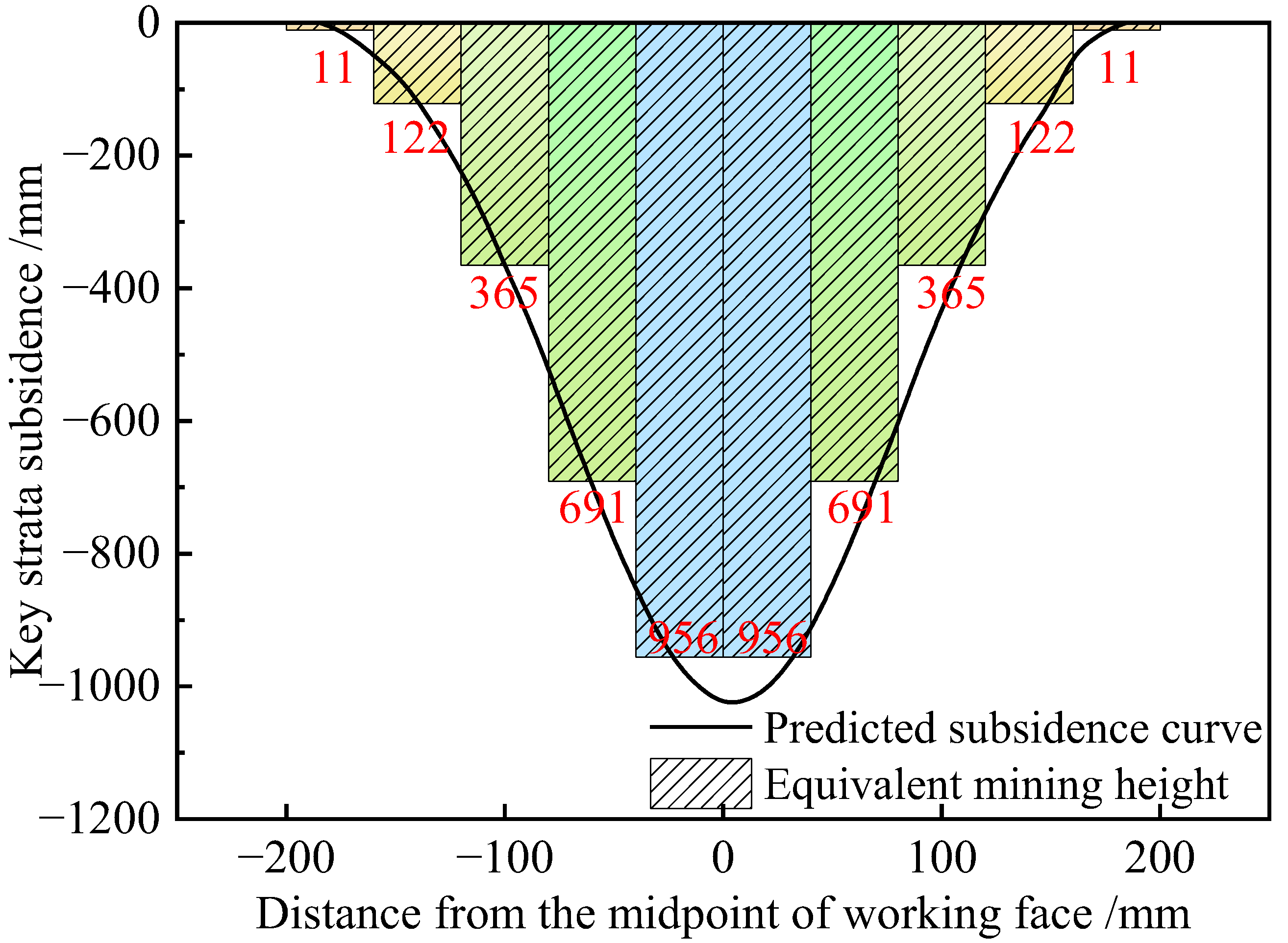
2.3.2. Determination Method of the Equivalent Mining Height for Key Strata Subsidence Space

In theory, substituting Equation (2) into Equation (25) allows for the derivation of the ground surface subsidence curve. However, due to Equation (2) being a piecewise function with multiple parameters, the computational burden is substantial. Therefore, to balance computational efficiency and accuracy demands in on-site engineering applications, it is practical to simplify the space below the key strata into several rectangular spaces, each with varying mining heights, shown as Figure 5.
The height calculation formula for each rectangular space (mth) can be expressed as follows:
h m = x m x m + 1 w ( x ) d x x m + 1 x m
According to the principle of superposition, the total ground surface subsidence caused by all rectangular equivalent subsidence spaces of the key strata is
W ( x ) = q 0 m = 1 n x m x m + 1 h m r exp ( π ( x u ) 2 r 2 ) d u

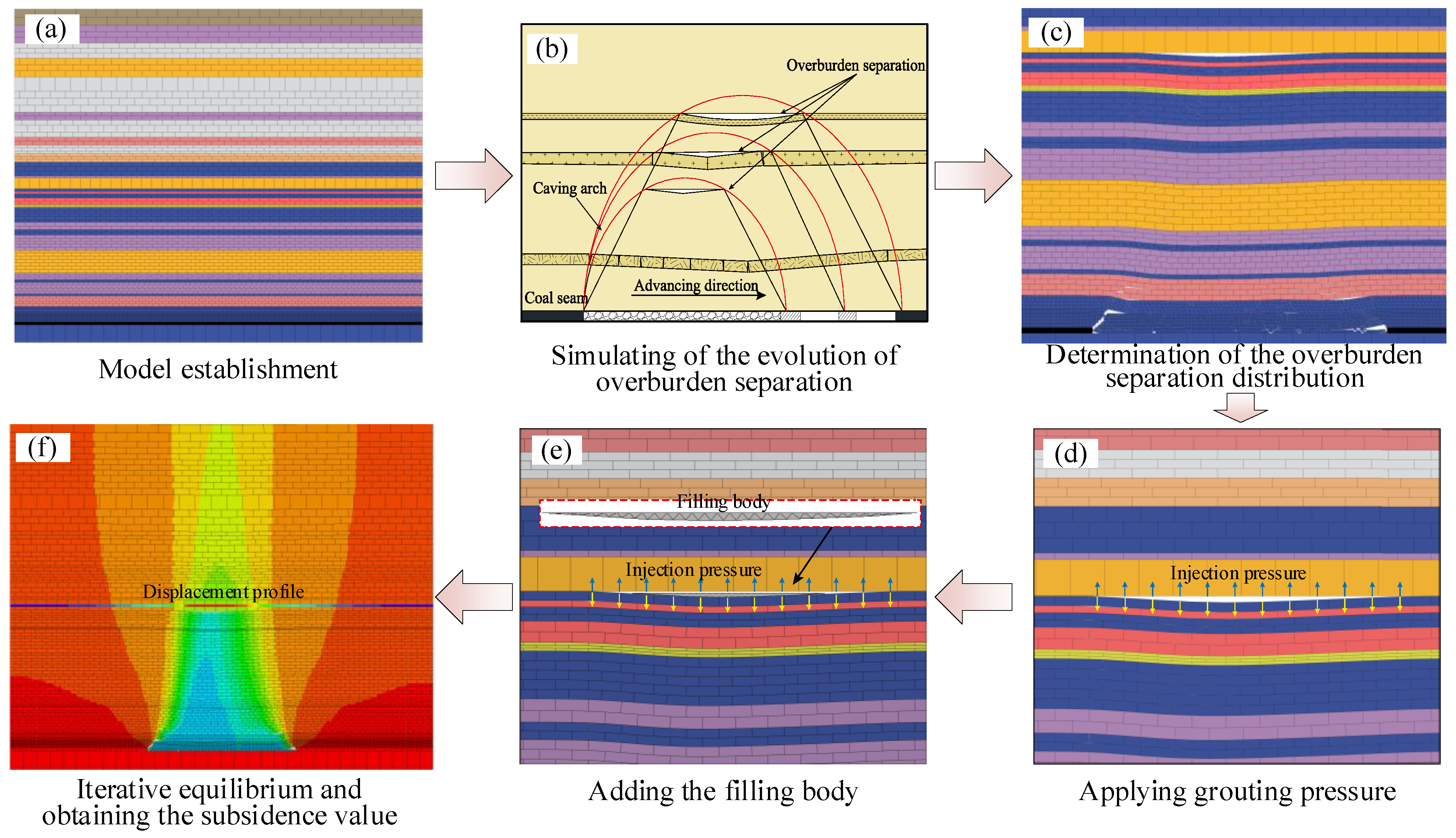
2.4. Discrete Element Numerical Simulation Method of Grouting into Overburden Separation

Compared to continuous media methods, the discontinuous media approach is better suited for simulating phenomena such as shear and tensile failures, as well as the expansion of fractures in rock layers. This method also provides a more accurate depiction of the filling process during grouting. In this study, the discrete element method software, 3DEC 7.0, was utilized to numerically simulate the grouting process into overburden separation and to explore the subsidence behavior of the overburden. The primary steps of the proposed numerical simulation method, illustrated in Figure 6, include the following: ① Establishing a numerical model of the mining field and overlying rocks, as shown in Figure 6a; ② Simulating the dynamic evolution of overburden separation during working face excavation, as shown in Figure 6b; ③ Determining the spatial geometric characteristics of overburden separation for a given width of working face, as shown in Figure 6c; ④ Applying grouting pressure within the separated space between layers, as shown in Figure 6d; ⑤ Establishing a filling body within the separated space beneath key strata and assigning them a biaxial yield constitutive model after grid division, as shown in Figure 6e; ⑥ Releasing grouting pressure and iterating the numerical model until equilibrium while recording subsidence information of ground surface and key strata, as shown in Figure 6f.
This numerical simulation method enables the subsidence simulation of key strata and the ground surface under various injection–extraction ratios by incorporating fill blocks of different volumes. This approach enables a comprehensive simulation of the entire grouting process, closely mirroring actual grouting projects. Additionally, it allows for the accurate prediction of subsidence reduction resulting from grouting projects.

3. Case Study

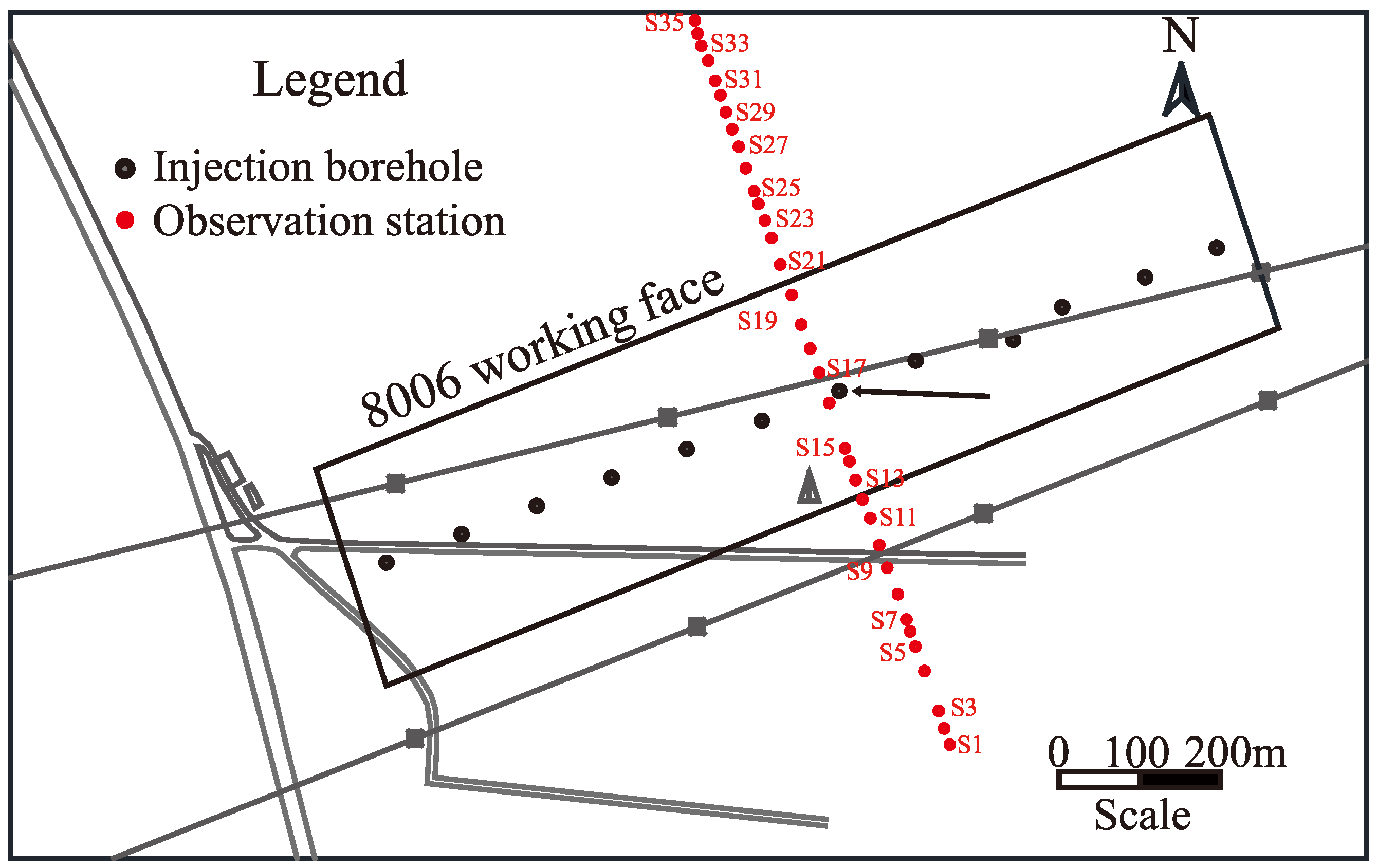
3.1. Project Overview

The 8006 working face of the Wuyang Coal Mine, located in Changzhi, Shanxi Province, serves as a pivotal example (illustrated in Figure 7) [33]. This working face measures 280 m in width and 1280 m in advance length. It exploits the No. 3 coal seam of the Shanxi Formation, which has an average thickness of 5.5 m and is situated at an average depth of 620 m, yielding approximately 2.233 million tons of coal resources. The mining method employed is the longwall top-coal caving technique, and roof management is achieved through the natural span falling method. Several high-value and immovable structures are present on the ground surface above this working face, including eight 550 kV high-voltage towers, a gas station, and an oil station. To protect these structures from potential damage due to ground surface subsidence, grouting into overburden separation was implemented at the working face. The mining operations spanned from May 2021 to November 2022, while the grouting period extended from June 2021 to December 2022. During this time, approximately 650,000 tons of dry fly ash were injected into the overburden, achieving an actual injection–extraction ratio of 33%.
Figure 8 illustrates the layout diagram of surface subsidence monitoring stations at the 8006 working face of the Wuyang Coal Mine.

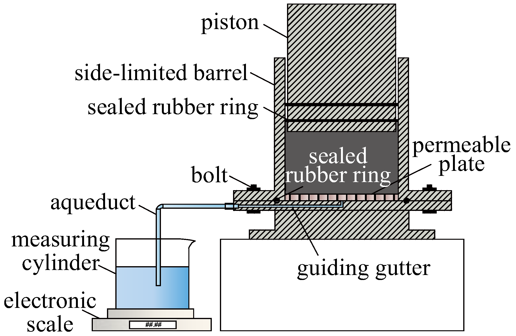
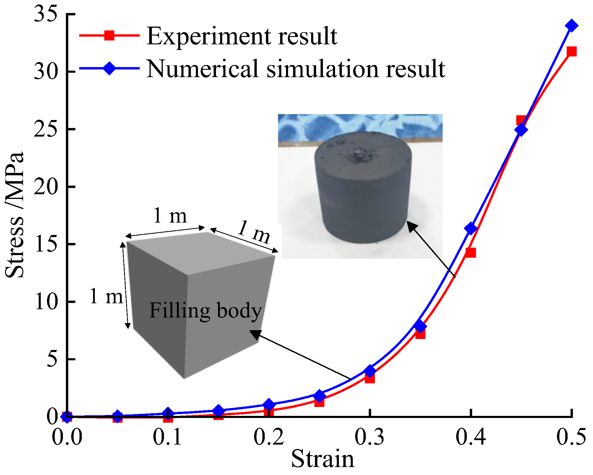
3.2. Compaction Characteristic Parameters of Filling Materials

The accuracy of numerical simulation results is dependent on the rationality of the constitutive model used. Given that fly ash filling is a granular material, its stress–strain characteristics markedly differ from those of rock materials. Therefore, it is necessary to investigate the compression characteristics of fly ash filling under grouting into overburden separation conditions.
During the grouting process, the fly ash slurry, as it moves through the separation, experiences continuous water drainage due to pressure and seepage within the rock layers, ultimately resulting in a compacted filling body. To simulate this real-world condition in a laboratory setting, a fly ash slurry compressor, which emulates a confined environment, is used. This apparatus allows for the replication of both the stress experienced by the filling slurry and the water loss processes occurring within rock layers [13]. The schematic diagram of this slurry compactor is presented in Figure 9. The compactor consists of an outer cylinder that acts as a closed system with an inner cavity at the bottom connected to a water outlet. Equipped with a sieve plate and filter screen, the device effectively simulates the ongoing water loss during the slurry consolidation process. Prior to starting the experiment, lubricating oil is applied between the piston and the barrel wall to reduce friction. During the experiment, pressure is exerted on the slurry by a press machine acting on the piston, mimicking the gravitational force of the overlying strata. Both the pressure and the displacement experienced by the fly ash filling body are recorded in real time. The sample used in this experiment was sourced from fly ash utilized in the grouting operations at the Wuyang Coal Mine in Changzhi City, Shanxi Province, China. The water-to-ash ratio used was 1.15:1, mirroring the specifications employed on-site for engineering purposes.
The double-yield constitutive model is particularly effective for simulating the behavior of compacted bodies made from granular materials [34]. To determine the parameters for this model, the confined compression test was numerically simulated. The simulation involved a unit block configured as a 1 m cube, with displacement constraints fixed at the periphery and the bottom edge of the model, while a fixed vertical velocity was applied to the top. Material parameters for the model were established through a trial-and-error inversion method. This approach facilitated the fine-tuning of parameters to best match the observed experimental data. The comparison of the final simulation results with actual experimental data is depicted in Figure 10. Additionally, the mechanical properties derived from the experiments on the fly ash filling body used in overburden separation are detailed in Table 1.

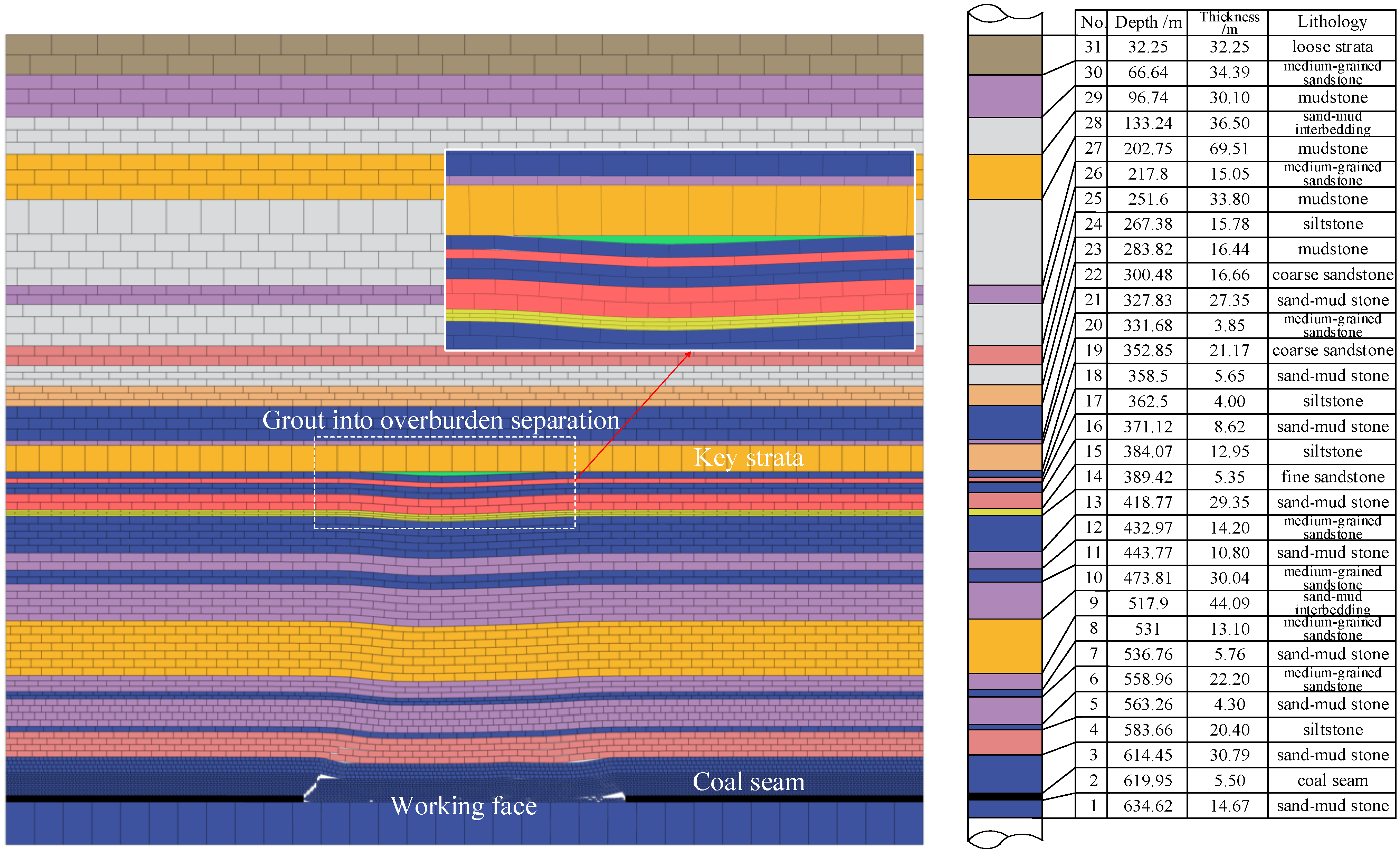
3.3. Construction of Numerical Model

A numerical simulation model, as depicted in Figure 11, was established to reflect the specific geological conditions and grouting filling scenarios of the 8006 working face at the Wuyang Coal Mine. The model’s dimensions are set at 800 m × 4 m × 620 m, incorporating a working face width of 280 m, a mining height of 5.5 m, and a grouting hole depth of 352.85 m. To realistically simulate the natural environment, slip boundaries are implemented along the model’s perimeter, and lateral stress is applied to accommodate the varying burial depths of the mine. Additionally, a fixed boundary condition is enforced at the model’s base. For the characterization of rock mechanics, the Geological Strength Index (GSI) method along with the Hoek–Brown strength criterion was utilized to adjust the rock mechanics parameters across different strata layers. The resulting physical–mechanical parameters of the strata and the joints within the rock layers are comprehensively detailed in Table 2 and Table 3, respectively.
In order to avoid abnormal phenomena such as slurry leakage and ground heave caused by excessive injection of slurry, there is an ultimate injection–extraction ratio in the grouting into overburden separation project, which can be calculated as follows [11]:
α L = ( 1 h i c W tan φ ) 1 H c ( k p 1 ) M
Based on Equation (28) and the specific geological and grouting conditions at the engineering site, an ultimate injection–extraction ratio of 41.5% was determined for the 8006 working face. To explore the effects of varying ratios on overburden behavior, numerical simulation tests were conducted using injection–extraction ratios of 0%, 10%, 20%, 30%, and 40%.

4. Results and Discussion

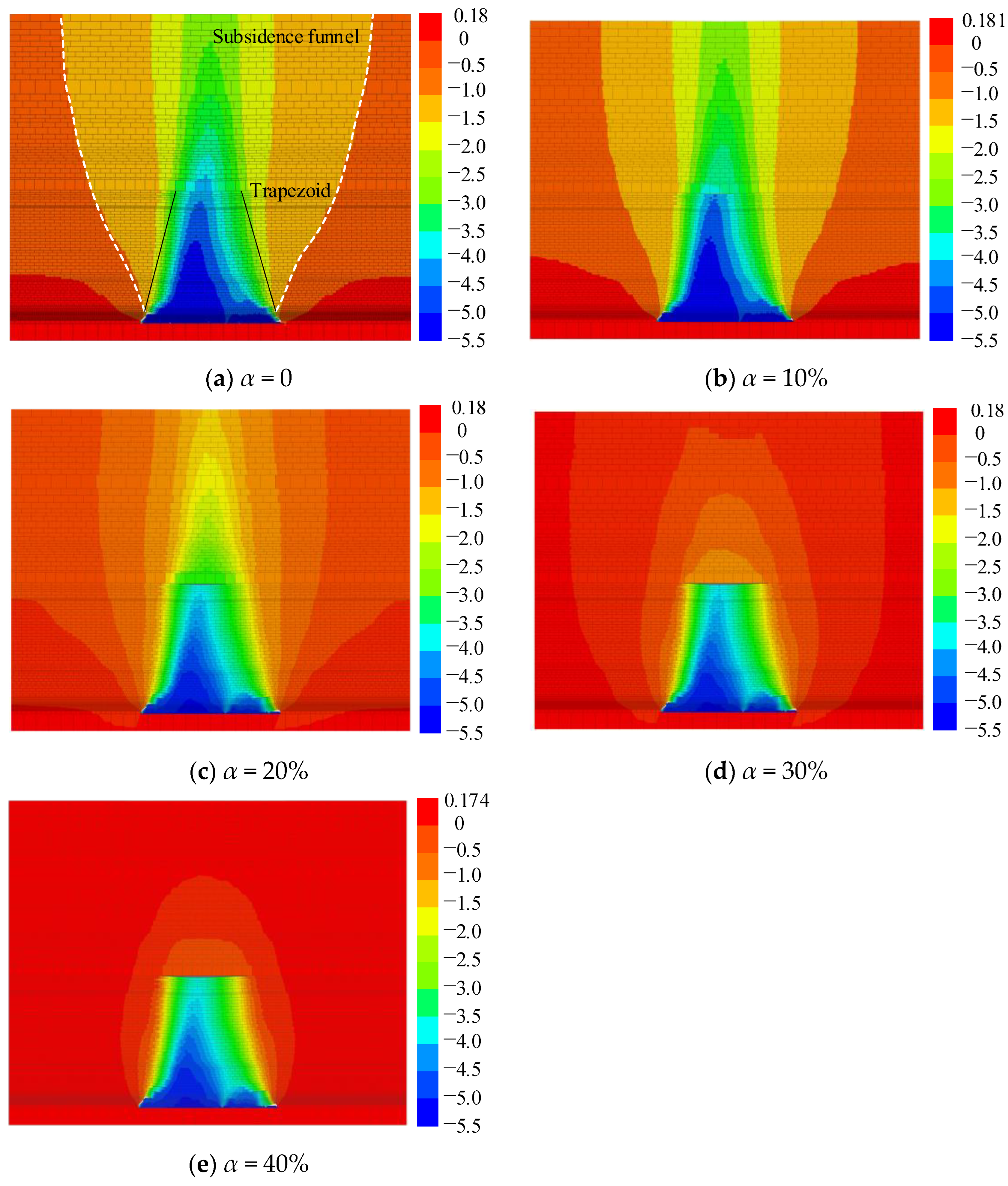
4.1. Results and Discussion of the Numerical Simulation

The movement characteristics of the overburden under these different injection–extraction ratios at this working face are depicted in Figure 12, based on the results of the numerical simulations.
According to Figure 12a, the movement of rock layers and surface subsidence without grouting displays a funnel-shaped pattern, with the fractured rock layers in the overburden space arranged trapezoidally. Figure 12b–e demonstrate that the fly ash filling body significantly impedes the continuous displacement of rock layers at both the upper and lower interfaces of separation, effectively reducing the subsidence of key strata and their overlying rock layers. Specifically, Figure 12b,c show that at injection–extraction ratios of 0.1 and 0.2, the volume of the compacted filling body is not sufficient to provide effective support for the key strata. Figure 12d illustrates that at an injection–extraction ratio of 0.3, there is significant control over the subsidence of the key strata. This control, combined with the unloading expansion of the overburden, results in a noticeable effect on surface subsidence mitigation. Figure 12e reveals that as the injection–extraction ratio approaches 0.4, close to its ultimate value, the fly ash filling body effectively fills the entire separation space, providing robust support for the key strata and minimizing surface subsidence. In practical engineering applications, maintaining a stable separation space for an extended period becomes challenging due to the continuous advancement of the working face. Additionally, the slurry grouting process typically requires considerable time to complete. Consequently, achieving the ultimate injection–extraction ratio is nearly impossible in real-world scenarios. However, this ratio serves as an essential estimation basis for determining the maximum cement consumption during grouting into overburden separation projects.
According to the numerical simulation study, the subsidence curves of key strata and ground surface under different injection–extraction ratios are shown in Figure 13.
According to Figure 13a, the impact of the injection–extraction ratio on the subsidence of key strata is pronounced, with both the key strata and ground surface experiencing a progressive decrease in subsidence as the injection–extraction ratio increases. Without grouting, the maximum subsidence recorded for the key strata is 4849 mm. However, when the injection–extraction ratio is increased to 40%, this subsidence dramatically reduces to just 235 mm. This indicates that an appropriately managed injection–extraction ratio in grouting into overburden separation projects can effectively support the key strata and significantly reduce overburden subsidence. Additionally, the alignment of numerical simulation results with theoretical calculations confirms the reliability and practical applicability of using the elastic foundation beam theory to address the deflection of key strata.
In Figure 13b, the surface subsidence curve mirrors the laboratory test results cited in [35], showcasing a funnel-shaped subsidence pattern across various injection–extraction ratios. This pattern highlights the effectiveness of the grouting process, particularly at an injection–extraction ratio of 40%, where the maximum ground surface subsidence is dramatically reduced to only 76 mm, in stark contrast to the 3485 mm observed in ungrouted conditions. This significant reduction clearly demonstrates that grouting into overburden separation is a highly effective method for mitigating surface subsidence, thereby enhancing the stability and safety of surface structures.
The influence of ground surface tilting deformation on the stability of surface structures is more pronounced than subsidence [36], especially for tall structures with small base areas and significant heights, such as high-voltage transmission towers, chimneys, and water towers, which are highly sensitive to tilting deformation. Even a slight tilt in the ground surface can result in significant overturning moments for these structures. Therefore, determining the influence of different water injection–extraction ratios on the variation law of surface tilt is particularly important. The curves depicting surface tilt under different injection–extraction ratios are presented in Figure 14, where the deformation value i represents the corresponding slope of the subsidence curve.
According to “The Specification of Design for Pillars of Buildings, Water Bodies, Railway, Main Shafts, and Drifts [37]”, surface tilt is categorized into four damage grades: Damage Grade I denotes slight damage requiring minimal repair for tilts less than 3 mm/m; Damage Grade II indicates mild damage for tilts less than 6 mm/m; Damage Grade III represents moderate damage for tilts less than 10 mm/m; and Damage Grade IV requiring significant repairs or potential demolition and applies to tilts exceeding 10 mm/m. Figure 14 demonstrates the consequences of varying injection–extraction ratios on surface tilt at a working face: below 10% results in severe damage; below 20% leads to moderate damage; below 30% causes mild damage, and at 40%, the tilt remains below 3 mm/m, indicating only minor damage that does not necessitate repairs. Therefore, maintaining an injection–extraction ratio above 30% is advisable to minimize damage to surface structures during grouting into overburden separation.

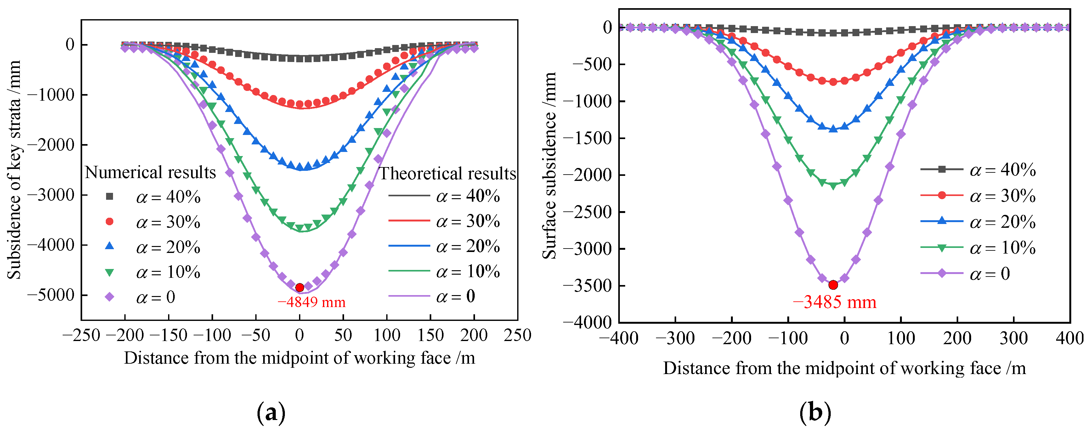
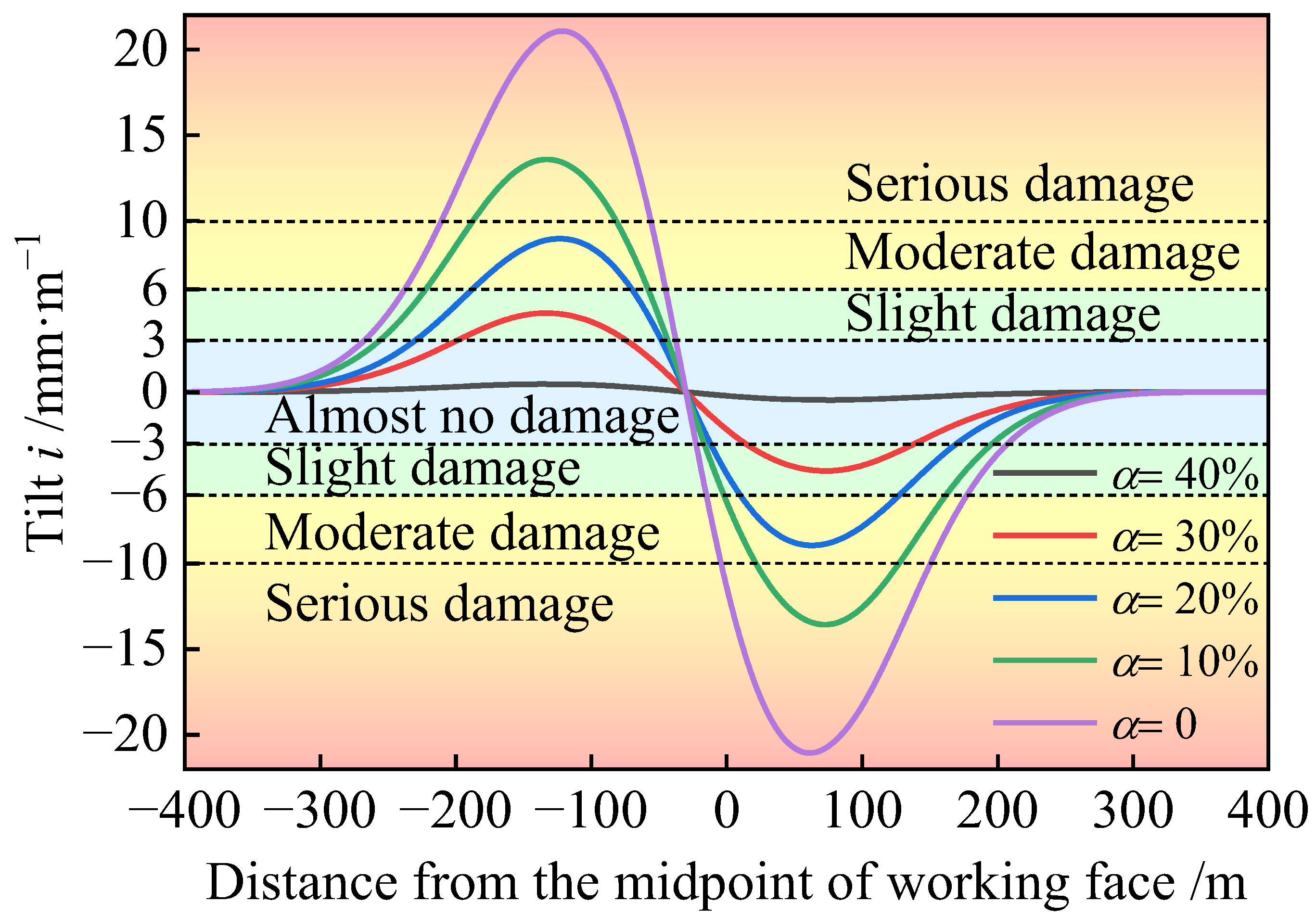
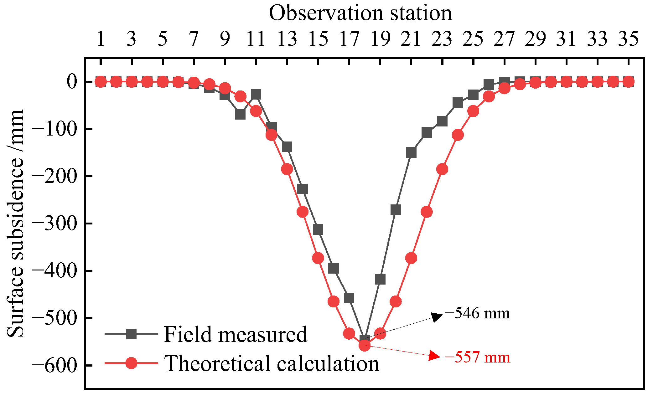
4.2. Verification of Subsidence Prediction Model for Ground Surface

The surface subsidence prediction model proposed in Section 2.2 is utilized to forecast the control effect of surface subsidence for the grouting into overburden separation project at 8006 working face of the Wuyang Coal Mine in Changzhi, Shanxi. The model’s accuracy is validated through on-site measurement data.
According to the equivalent mining height theory method described in Section 2.3.2, the subsidence space of the key strata was segmented into ten rectangular spaces, each characterized by different mining heights. In addition, considering the geological mining conditions of the mining area, a subsidence coefficient q0 of 0.73 and a main influencing tangent value tanβ of 2.711 were employed to derive the predicted subsidence values of 8006 working face. Figure 15 illustrates the average subsidence height for each of these spaces, alongside the corresponding subsidence curve for the key strata of the 8006 working face, where an injection–extraction ratio of 33% was implemented.
The predicted values were then compared with the on-site measured values, as shown in Figure 16.
According to Figure 16, the maximum measured surface subsidence at the grouting into overburden separation working face is 546 mm, while the corresponding theoretical prediction is 557 mm. The minimal relative error of 2% between these measurements confirms the accuracy of the prediction model, demonstrating a high degree of concordance between the predicted and measured subsidence curves on the ground surface. This concordance validates the effectiveness of the proposed prediction method in realistically reflecting conditions encountered in engineering practice. Further, combining this with the data from Figure 13b, where the theoretical predicted value of maximum surface subsidence without grouting measures 3485 mm, it is evident that the grouting into overburden separation reduces the maximum ground subsidence by 2939 mm. This represents a substantial reduction rate of approximately 84.3%, underscoring the significant impact of the grouting process in mitigating surface subsidence.
The ground surface tilt values of the monitoring station are plotted as a curve, as shown in Figure 17. The figure illustrates that the implementation of a grouting into overburden separation project with an injection–extraction ratio of 33% at the working face achieved a maximum surface tilt of less than 3 mm/m. This outcome successfully meets the specified stability requirements for surface structures.

5. Conclusions

This paper introduces a calculation model for the deflection of key strata and a prediction model for ground surface subsidence under conditions of grouting into overburden separation. These models are suitable for conditions such as horizontal or nearly horizontal coal seams, longwall mining with natural roof-caving management, thick and uniformly hard rock layers as key strata, and grouting in the void space beneath the key layer for subsidence reduction. Also, these models incorporate analytical methods such as elastic foundation beam theory and the principle of equivalent mining height. Additionally, a numerical simulation approach using the discrete element method is proposed for grouting into overburden separation. This method facilitates a thorough investigation of the subsidence and tilting characteristics of key strata and ground surfaces under different injection–extraction ratios. The accuracy and reliability of the ground subsidence prediction model were substantiated by comparing it with on-site measured data. The main findings from this study are summarized as follows:
(1)
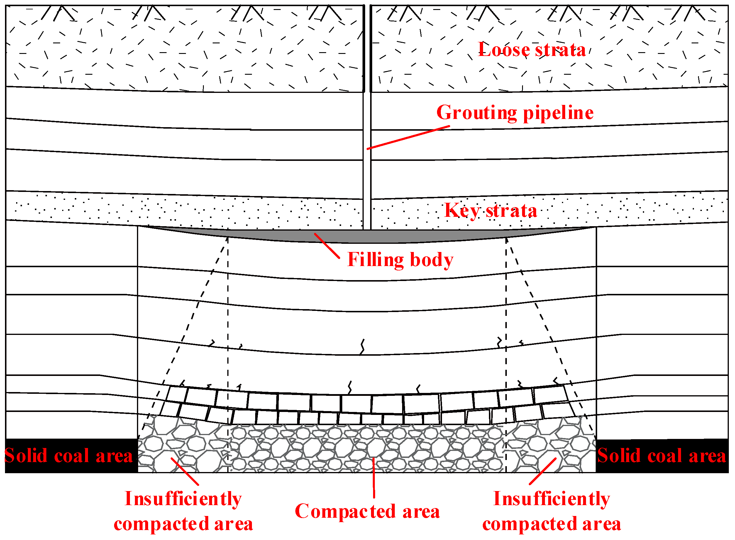
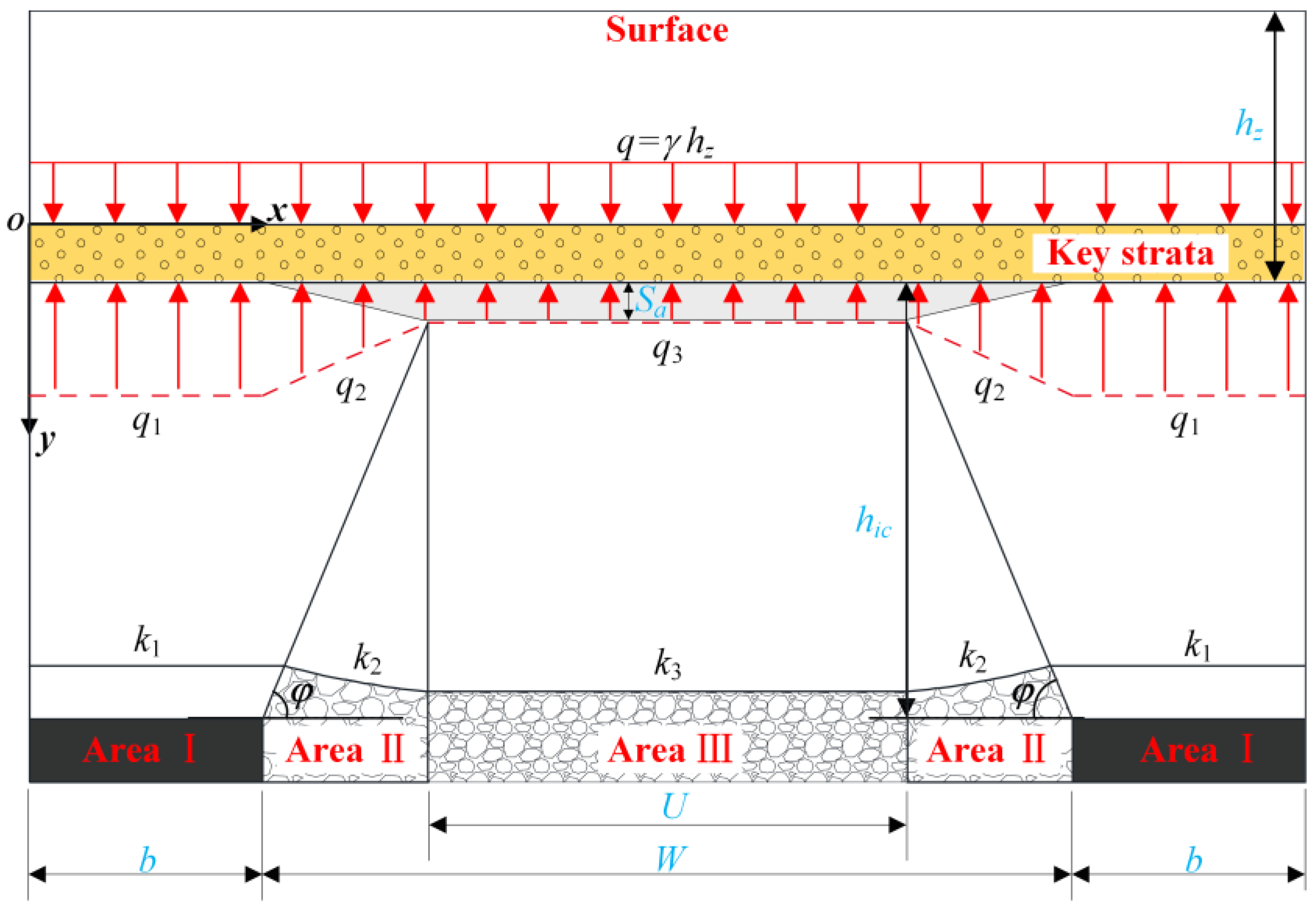
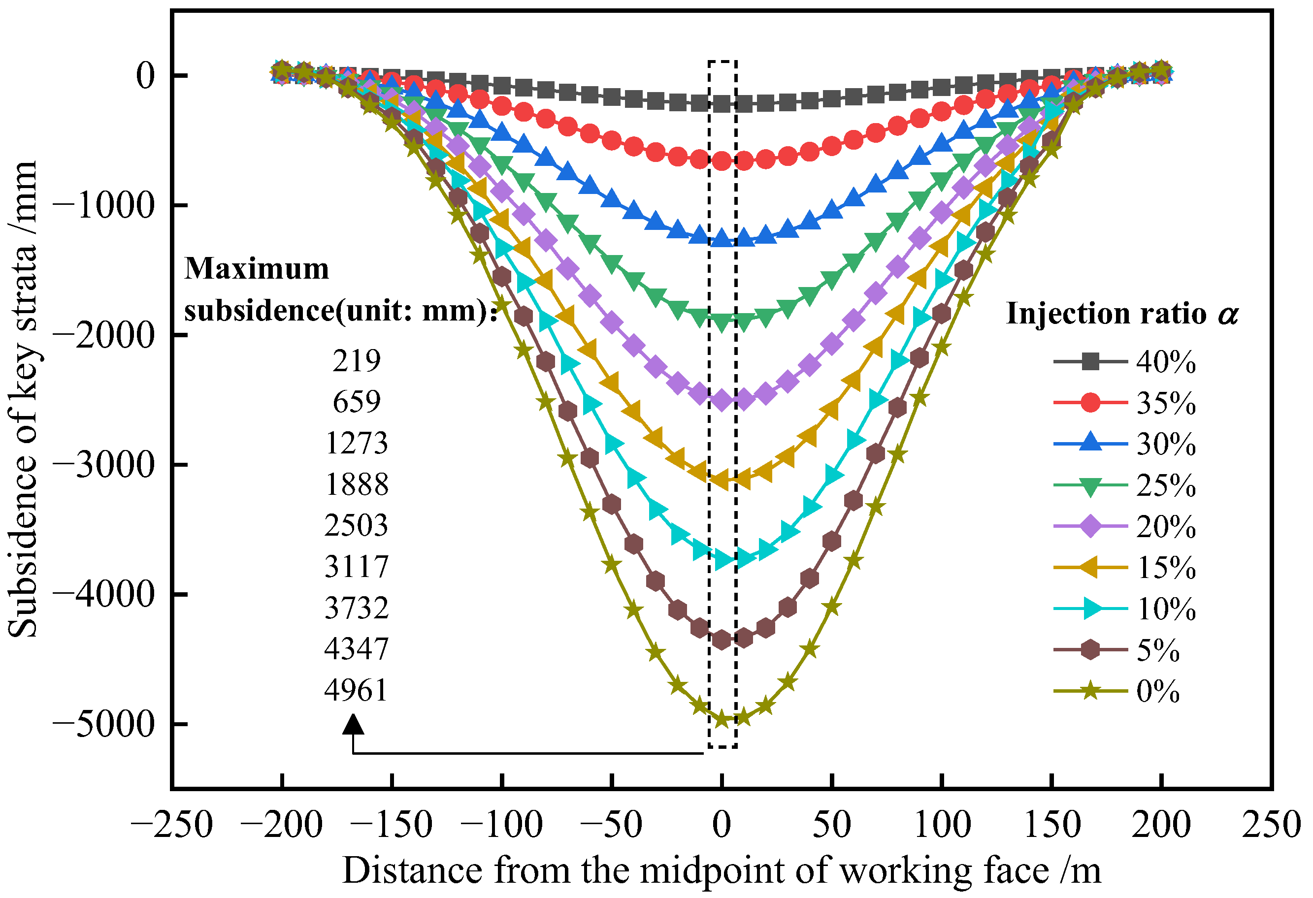
The coal–rock mass beneath the key strata is treated as an elastic foundation, segmented into a solid coal area, an insufficiently compacted area, and a compacted area, all symmetrically distributed across the region. We proposed a method to calculate the elastic foundation coefficients for these distinct sections, along with a deflection calculation model for the key strata. Theoretically, the maximum subsidence of the key strata, in the absence of grouting, is determined to be 4961 mm. However, an increase in the injection–extraction ratio consistently results in a reduction in this maximum subsidence, emphasizing its crucial role in controlling subsidence within the key strata.
(2)
Using a discrete element numerical simulation method for grouting into overburden separation, the subsidence behavior of the overburden on the working face under varying injection–extraction ratios was studied. It was observed that as the injection–extraction ratio increases, the subsidence of both the key strata and the ground surface progressively decreases. The alignment of the subsidence curves for key strata from the numerical simulations with those from the proposed calculation model underscores the reliability of the latter. The use of fly ash as a filling material plays a crucial role in impeding the ongoing displacement of rock layers at both the upper and lower interfaces of the separation. This effectively reduces the subsidence of key strata and their overlying rock layers. Notably, when the injection–extraction ratio is set at 40%, the maximum surface subsidence observed in numerical simulations is only 76 mm, compared to a substantial 3485 mm in scenarios without grouting.
(3)
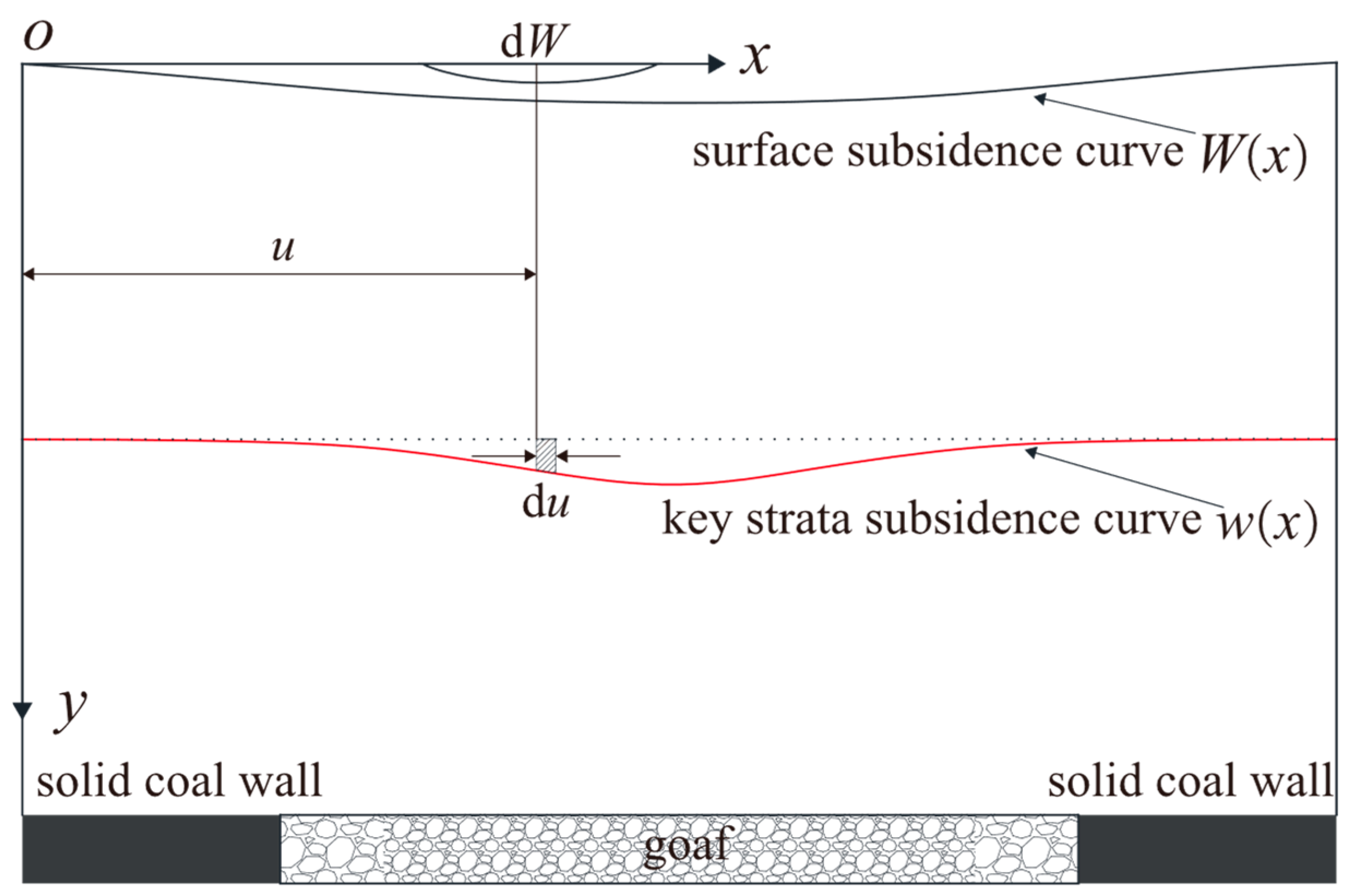
A predictive model for surface subsidence, incorporating the equivalent mining height theory and the probability integral method, was developed to assess conditions under grouting into overburden separation. This model’s reliability was validated through on-site measurement data from the 8006 working face at the Wuyang Coal Mine. The maximum observed surface subsidence at the grouted working face was recorded at 546 mm, closely aligning with the theoretical prediction of 557 mm. This results in a relative error of merely 2%, demonstrating the model’s high accuracy. Following the implementation of a grouting into overburden separation project with an injection–extraction ratio of 33% at the working face, the maximum surface tilt recorded was less than 3 mm/m. This performance meets the specified stability requirements for surface structures, confirming the effectiveness of the grouting intervention in managing subsidence and maintaining structural integrity.

Author Contributions

Conceptualization, F.M.; Methodology, W.L.; Software, W.L.; Resources, W.L.; Data curation, W.L.; Writing—original draft, F.M.; Writing—review & editing, S.J.; Supervision, H.N. All authors have read and agreed to the published version of the manuscript.

Funding

This research was funded by the National Key Research and Development Program of China (Grant No. 2023YFC3804200) and Fundamental Research Funds for the Central Universities (2022QN1024).

Institutional Review Board Statement

Not applicable.

Informed Consent Statement

Not applicable.

Data Availability Statement

The raw data supporting the conclusions of this article will be made available by the authors on request.

Conflicts of Interest

The authors declare no conflict of interest.

References

  1. Guo, W.; Guo, M.; Tan, Y.; Bai, E.; Zhao, G. Sustainable development of resources and the environment: Mining-induced eco-geological environmental damage and mitigation measures—A case study in the Henan coal mining area, China. Sustainability 2019, 11, 4366. [Google Scholar] [CrossRef]
  2. Wang, J.; Ma, J.; Yang, K.; Yao, S.; Shi, X. Effects and laws analysis for the mining technique of grouting into the overburden bedding separation. J. Clean. Prod. 2021, 288, 125121. [Google Scholar] [CrossRef]
  3. Jing, Z.; Wang, J.; Zhu, Y.; Feng, Y. Effects of land subsidence resulted from coal mining on soil nutrient distributions in a loess area of China. J. Clean. Prod. 2018, 177, 350–361. [Google Scholar] [CrossRef]
  4. Xu, Y.; Lin, B.; Liu, T.; Cao, J.; Liu, T. Influence law and control mechanism of overburden isolated grout injection on methane emission in the working face. J. Clean. Prod. 2023, 430, 139612. [Google Scholar] [CrossRef]
  5. Meng, F.F.; Piao, C.D.; Shi, B.; Sasaoka, T.; Shimada, H. Calculation model of overburden subsidence in mined-out area based on Brillouin optical time-domain reflectometer technology. Int. J. Rock Mech. Min. Sci. 2021, 138, 104620. [Google Scholar] [CrossRef]
  6. Xuan, D.; Xu, J.; Wang, B.; Teng, H. Borehole investigation of the effectiveness of grout injection technology on coal mine subsidence control. Rock Mech. Rock Eng. 2015, 48, 2435–2445. [Google Scholar] [CrossRef]
  7. Zhao, J.; Konietzky, H. Numerical analysis and prediction of ground surface movement induced by coal mining and subsequent groundwater flooding. Int. J. Coal Geol. 2020, 229, 103565. [Google Scholar] [CrossRef]
  8. Li, H.; Zhang, B.; Bai, H.; Wu, J.; Meng, Q.; Xiao, N.; Wu, G. Surface water resource protection in a mining process under varying strata thickness—A case study of Buliangou Coal Mine, China. Sustainability 2018, 10, 4634. [Google Scholar] [CrossRef]
  9. Fan, K.; He, J.; Li, W.; Chen, W. Dynamic evolution and identification of bed separation in overburden during coal mining. Rock Mech. Rock Eng. 2022, 55, 4015–4030. [Google Scholar] [CrossRef]
  10. Xuan, D.; Xu, J. Longwall surface subsidence control by technology of isolated overburden grout injection. Int. J. Min. Sci. Technol. 2017, 27, 813–818. [Google Scholar] [CrossRef]
  11. Xuan, D.; Xu, J.; Wang, B.; Teng, H. Investigation of fill distribution in post-injected longwall overburden with implications for grout take estimation. Eng. Geol. 2016, 206, 71–82. [Google Scholar] [CrossRef]
  12. Li, Y.X.; Ma, J.; Yang, K.M.; Jiang, K.G.; Gu, X.R.; Peng, L.S.; Chen, X.Y. Isolated overburden grout injection technology mining and grouting parameters discussion and optimization. Environ. Earth Sci. 2024, 83, 1–30. [Google Scholar] [CrossRef]
  13. Zhang, L.; Xu, J.; Xuan, D.; Gan, M. Experimental and applied research on compression properties of slurry used for isolated overburden grout injection. J. China Coal Soc. 2017, 42, 1117–1122. [Google Scholar] [CrossRef]
  14. Fei, Y.; Liu, S.; Xu, Y.; Zhao, L. Failure analysis of thin bedrock and clay roof in underground coal mining: Case study in Longdong coal mine. Int. J. Geomech. 2020, 20, 04020187. [Google Scholar] [CrossRef]
  15. Wang, Y.; Kong, D.; Wu, G.; Cheng, Z.; Song, G.; Shang, Y. Failure mechanism and movement characteristics of overlying strata in longwall mining face with thick aquifer. Rock Mech. Rock Eng. 2024, 57, 6787–6809. [Google Scholar] [CrossRef]
  16. Wu, F.; Gao, Z.; Liu, H.; Yu, X.; Gu, H. Theoretical discrimination method of water-flowing fractured zone development height based on thin plate theory. Appl. Sci. 2024, 14, 6284. [Google Scholar] [CrossRef]
  17. Wu, L.; Zhang, J.; Wang, Z.; Ma, D.; Wang, G. Research on formation mechanism of the mining-induced horizontal fractures in rock strata separation in the Jurassic coalfield, Huang long, Shaanxi, China. Energy Rep. 2020, 8, 9711–9723. [Google Scholar] [CrossRef]
  18. Zhang, J.; Rui, Q.; Yang, Y.; Chen, J.; Shen, W.; Yuan, Y.; Liu, W. Roof movement and instability fracture characteristics in shallow-buried thin coal seam conventional mining faces. Geomech. Geophys. Geo-Energy Geo-Resour. 2024, 10, 27. [Google Scholar] [CrossRef]
  19. Wang, K.; Li, J.; Jin, Z. Influence of the primary key stratum on surface subsidence during longwall mining. Sustainability 2022, 14, 15027. [Google Scholar] [CrossRef]
  20. Li, Y.; Wang, N.; Lei, X.; Li, T.; Ren, Y. The subsidence mechanisms of primary key stratum with different factors: A case study. Geotech. Geol. Eng. 2023, 41, 4351–4366. [Google Scholar] [CrossRef]
  21. Sun, Q.; Jiang, Y.; Ma, D.; Zhang, J.; Huang, Y. Mechanical model and engineering measurement analysis of structural stability of key aquiclude strata. Min. Metall. Explor. 2022, 39, 2025–2035. [Google Scholar] [CrossRef]
  22. Zhao, B.; Guo, Y.; Mao, X.; Zhai, D.; Zhu, D.; Huo, Y.; Wang, J. Prediction method for surface subsidence of coal seam mining in Loess Donga based on the probability integration model. Energies 2022, 15, 2282. [Google Scholar] [CrossRef]
  23. Fu, Z.; Zhou, L.; Yu, K.; Li, W.; Chen, H. Fcield measurement and study on overburden fracture and surface subsidence law of solid filling mining under buildings. Shock. Vib. 2021, 2021, 5265333. [Google Scholar] [CrossRef]
  24. Xu, J.L.; Qin, W.; Xuan, D.Y.; Zhu, W.B. Influencing factors of accumulative effect of overburden strata expansion induced by stress relief. J. China Coal Soc. 2022, 47, 115–127. [Google Scholar]
  25. Cao, J.; Liu, T.; Shi, Y.; Lin, B.; Shen, J.; Xu, Y.; Liu, Y. Strata movement of overburden-separation grouting working face and its influence on gas emission during mining. Sustainability 2023, 15, 12792. [Google Scholar] [CrossRef]
  26. Xuan, D.; Li, J.; Zheng, K.; Xu, J. Experimental study of slurry flow in mining-induced fractures during longwall overburden grout injection. Geofluids 2020, 1, 8877616. [Google Scholar] [CrossRef]
  27. Sobhy, M. Buckling and free vibration of exponentially graded sandwich plates resting on elastic foundations under various boundary conditions. Compos. Struct. 2013, 99, 76–87. [Google Scholar] [CrossRef]
  28. Zhang, Y.; Cao, S.; Guo, S.; Wan, T.; Wang, J. Mechanisms of the development of water-conducting fracture zone in overlying strata during shortwall block backfill mining: A case study in Northwestern China. Environ. Earth Sci. 2018, 77, 543. [Google Scholar] [CrossRef]
  29. Xu, L.; Zhang, K.; Liu, X.; Chen, B.; Fan, T.; Gui, S. Deformation characteristic of key strata and control effect of surface subsidence in mining with grouting into overburden bed-separation. J. China Coal Soc. 2023, 48, 931–942. [Google Scholar]
  30. Ryder, J.A.; Wagner, H. 2D Analysis of Backfill as Means of Reducing Energy Release Rates at Depth; Chamber of Mines of South Africa: Johannesburg, South Africa, 1978; pp. 47–78. [Google Scholar]
  31. Salamon, M.D.G. Mechanism of caving in longwall coal mining. In Rock Mechanics Contributions and Challenges, Proceedings of the 31st U.S. Golden: Symposium; CRC Press: Boca Raton, FL, USA, 1990; pp. 161–168. [Google Scholar]
  32. Zhang, C.; Tu, S.; Zhao, Y.X. Compaction characteristics of the caving zone in a longwall goaf: A review. Environ. Earth Sci. 2019, 78, 1–20. [Google Scholar] [CrossRef]
  33. Wang, L. Research on Surface Subsidence Control by Grouting Injection Into Overburden Separation. Master’s Thesis, China University of Mining and Technology, Xuzhou, China, 2022. [Google Scholar]
  34. Wu, X.; Wang, S.; Gao, E.; Chang, L.; Ji, C.; Ma, S.; Li, T. Failure mechanism and stability control of surrounding rock in mining roadway with gentle slope and close distance. Eng. Fail. Anal. 2023, 152, 107489. [Google Scholar] [CrossRef]
  35. Ma, H.; Sui, W.; Ni, J. Environmentally sustainable mining: A case study on surface subsidence control of grouting into overburden. Environ. Earth Sci. 2019, 78, 320. [Google Scholar] [CrossRef]
  36. Li, H.; Guo, Z.; Hua, X.; Dai, B.; Zeng, X.; Zhao, Y. Research on the influence of backfilling mining in an iron mine with complex mining condsitions on the stability of surface buildings. Sustainability 2023, 15, 14733. [Google Scholar] [CrossRef]
  37. Coal Industry Ministry; People’s Republic of China. The Specification of Design for Pillars of Buildings, Water Bodies, Railway, Main Shafts and Drifts; China Coal Industry Publishing House: Beijing, China, 2017; pp. 53–56. [Google Scholar]
Figure 1. Schematic diagram of the grouting-induced subsidence reduction model.
Applsci 14 08766 g001
Figure 2. Deflection mechanical model of key strata with grouting into overburden separation.
Applsci 14 08766 g002
Figure 3. Deflection curve of key strata under different injection–extraction ratios.
Applsci 14 08766 g003
Figure 4. Schematic diagram of predicting surface subsidence by equivalent mining height theory.
Applsci 14 08766 g004
Figure 5. Equivalent rectangular subsidence space model.
Applsci 14 08766 g005
Figure 6. Diagram of numerical simulation method and steps for grouting into overburden separation.
Applsci 14 08766 g006
Figure 7. Project overview. (a) Location of the research mine; (b) surface and underground features of the working face [33].
Applsci 14 08766 g007
Figure 8. Layout diagram of grouting holes and surface subsidence monitoring stations for work face.
Applsci 14 08766 g008
Figure 9. Diagram of fly ash slurry compressor and its working principle.
Applsci 14 08766 g009
Figure 10. Stress–strain relationship curve of fly ash filling body.
Applsci 14 08766 g010
Figure 11. Numerical simulation model diagram of the discrete element method for grouting into overburden separation.
Applsci 14 08766 g011
Figure 12. Strata subsidence cloud map under different injection–extraction ratios.
Applsci 14 08766 g012
Figure 13. Influence of the injection–extraction ratio on the subsidence curve of the key strata and ground surface. (a) Comparison between numerical simulation and theoretical results of the subsidence curve for the key strata; (b) subsidence curve of the ground surface.
Applsci 14 08766 g013
Figure 14. Surface tilt along the midpoint line of the working face.
Applsci 14 08766 g014
Figure 15. Subsidence curve of key strata and average height of equivalent subsidence space.
Applsci 14 08766 g015
Figure 16. Comparison between measured and predicted values of ground surface subsidence in the grouting into overburden separation.
Applsci 14 08766 g016
Figure 17. The surface tilt along the observation station.
Applsci 14 08766 g017
Table 1. Mechanical property for fly ash filling body in overburden separation.
Density
(kg/m3)
Bulk Modulus
(GPa)
Shear Modulus
(GPa)
Cohesion
(MPa)
Friction
(°)
Tensile Strength
(MPa)
a 1
(MPa)
b 1c 1
(MPa)
9500.60.3018020810
1 a, b and c are the parameters of the empirical equation to calculate the cap pressure of the fly ash filling body, and the calculation model is: p = a e b ε m p s 1 + c ε m p s .
Table 2. Physical–mechanical parameters of strata.
No.LithologyDensity
(kg/m3)
Elastic Modulus (GPa)Poisson’s RatioCohesion
(MPa)
Internal Friction Angle (°)Tensile Strength
(MPa)
31Loose strata25000.20.440.222°0.03
30Medium-grained sandstone2560400.1913.942°6.1
29Mudstone2630250.233.940°3.7
28Sand–mud interbedding2440230.188.242°3.9
27Mudstone2630240.247.942°3.6
26Medium-grained sandstone2560410.2214.444°11.6
25Mudstone2630230.155.242°3.8
24Siltstone2560430.1617.239°4.32
23Mudstone2630190.227.542°3.8
22Coarse sandstone2450390.2116.942°5.8
21Sandy mudstone2530220.254.840°4.0
20Medium-grained sandstone2560440.228.542°7.1
19Coarse sandstone2450380.198.840°2.2
18Sandy mudstone2530220.223.139°4.0
17Siltstone2560380.2213.942°6.8
16Sandy mudstone2530240.186.544°4.0
15Siltstone2560370.228.842°4.7
14Fine sandstone2540260.218.539°5.8
13Sandy mudstone2530260.254.539°4.0
12Medium-grained sandstone2560330.226.142°5.0
11Sandy mudstone2530270.2310.039°4.3
10Medium-grained sandstone2560310.245.342°4.8
9Sand–mud interbedding2440260.155.439°3.8
8Medium-grained sandstone2560290.168.344°7.4
7Sandy mudstone2530250.227.942°3.8
6Medium-grained stone2560260.2415.842°3.8
5Sandy mudstone2530230.228.544°3.8
4Siltstone2560380.258.839°1.7
3Sandy mudstone2530220.1812.942°3.8
2Coal seam1400120.312.214°0.7
1Sandy mudstone2630240.232.340°3.8
Table 3. Physical–mechanical parameters of joints.
LithologyNormal Stiffness (GPa)Shear Stiffness
(GPa)
Tensile Strength (MPa)Cohesion (MPa)Internal Friction Angle (°)
Loose strata1.590.600.40.0114
Sand–mud interbedding4.891.934.30.1232
Siltstone6.742.728.70.2237
Fine sandstone6.552.609.20.2035
Medium-grained sandstone5.182.076.00.1632
Coarse sandstone4.911.985.50.1335
Mudstone4.471.752.30.0737
Sandy mudstone3.911.582.20.0936
Coal seam2.080.751.30.0530
Disclaimer/Publisher’s Note: The statements, opinions and data contained in all publications are solely those of the individual author(s) and contributor(s) and not of MDPI and/or the editor(s). MDPI and/or the editor(s) disclaim responsibility for any injury to people or property resulting from any ideas, methods, instructions or products referred to in the content.

