Article

Perspectives on Adhesive–Bolted Hybrid Connection between Fe Shape Memory Alloys and Concrete Structures for Active Reinforcements

College of Civil Engineering, Tongji University, Shanghai 200092, China
*
Author to whom correspondence should be addressed.
Appl. Sci. 2024, 14(19), 8800; https://doi.org/10.3390/app14198800
Submission received: 22 August 2024 / Revised: 18 September 2024 / Accepted: 26 September 2024 / Published: 30 September 2024

Abstract

:
The prestressed active reinforcement of concrete structures using iron-based shape memory alloys (Fe-SMAs) is investigated in this experimental study through three connecting methods: adhesive–bolted hybrid connection, bolted connection, and adhesively bonded connection by activating at elevated temperatures (heating and cooling) and constraining deformation to generate prestress inside Fe-SMAs, through which compressive stress is generated in the parent concrete structures. In tests, the Fe-SMA is activated at 250 °C using a hot air gun, generating a prestress of 184.6–246 MPa. The experimental results show that local stress concentration in the concrete specimen and Fe-SMA plate around the hole is caused by the bolted connection. The adhesively bonded connection is prone to softening and slip of the structural adhesive during the activation process, thereby reducing the overall recovery force of Fe-SMAs. The adhesive–bolted hybrid connection effectively mitigates the local stress concentration problem of concrete and Fe-SMAs at anchor holes, while avoiding the prestress loss caused by the softening and slip of structural adhesive during elevated-temperature activation, achieving good reinforcement effect. This study on the connection methods of an Fe-SMA for reinforcing concrete structures provides both experimental support and practical guidance for its engineering application, offering new perspectives for future research.

1. Introduction

Concrete structures are currently one of the most widely used structural forms in the field of civil engineering. However, during the normal use of concrete structures, concrete inevitably produces cracks, aging and local damage. Especially in some special usage environments, such as humid environments and freeze–thaw cycles, concrete cracking will expose the steel bars, leading to further corrosion of the steel bars and having a serious impact on the whole concrete structures [1,2,3]. Therefore, the repair and reinforcement of concrete structures have always been a hot topic in the field of civil engineering [4]. Currently, traditional reinforcement methods for concrete structures include increasing the cross-sectional area, bonding steel plates, and bonding carbon fiber-reinforced polymer reinforcement. These methods are effective attempts in structural reinforcement but still have many limitations [5,6,7,8,9,10].
The emergence of shape memory alloys (SMAs) provides a new approach for strengthening concrete structures. SMA is a new type of intelligent material with shape memory effect (SME), which can recover its initial shape after heating. By effectively suppressing this deformation recovery effect, prestress can be introduced inside the structural components to achieve active reinforcement of existing structures [11,12,13,14,15]. There are dozens of existing SMAs in the world, among which the most significant ones in the field of civil engineering are iron-based shape memory alloys (Fe-SMAs) and nickel–titanium shape memory alloys (NiTi-SMAs) [16,17]. Compared to NiTi-SMAs, an Fe-SMA has a lower cost and superior strength, plasticity, processability, and fatigue performance. Therefore, an Fe-SMA is more suitable for a large number of applications in the field of civil engineering, especially for reinforcement and repair [18,19]. At present, the commonly used Fe-SMA materials in the international construction market have the characteristics required for structural reinforcement. By constraining them to the parent structures and activating them, sufficient prestress can be provided via SME [20,21,22,23,24].
In addition, when using Fe-SMAs to reinforce the structure, it is necessary to ensure a reliable connection between it and the parent structure. Therefore, the selection of reinforcement connections is of great significance. Currently, the widely used connection methods between structures mainly include bolted connections, welded connections and bonded connections [25,26,27,28,29,30]. Bolted connections are widely used in structural connections due to their convenient construction process and excellent durability. Qiang et al. [25] used bolt-anchored Fe-SMA plates to reinforce steel beams. The results showed that the bolt anchoring device had good performance, and no slip or fracture was observed during pretightening and activation, indicating that Fe-SMA can be used for reinforcement and repair of damaged steel structures. Vůjtěch et al. [31] used bolted connections to anchor the Fe-SMA for prestressed repair of steel bridges that have been in service for 113 years, achieving good reinforcement results and further confirming the effectiveness of this reinforcement method. However, bolted connections require pre-drilled holes in the structure, and local stress concentrations usually occur around the bolt holes, which is not conducive to structural stress. Non-destructive bonding connections can avoid structural openings and introduce new vulnerable sources, ensure uniform stress transmission between components, avoid stress concentration problems in bolted connections, and have superior fatigue resistance. Lv et al. [18] used adhesively bonded Fe-SMA strips to proactively strengthen u-rib butt-welded joints in steel bridge decks and found that the SMA-strengthened specimens achieved better remaining fatigue life than the CFRP-repaired ones. Wu et al. [30] conducted an experimental study on the bonding properties of an Fe-SMA to a steel-bonded interface, and the reliability of the reinforced-steel structures with the Fe-SMA by adhesive bonding was verified. However, the mechanical properties of bonded connections are easily degraded by humid and hot environments, and they can not continue to bear loads in the event of a fire. Their poor disaster resilience hinders their widespread application in the field of civil engineering.
Given the advantages and limitations of both bonded and bolted connections, this paper optimizes the connection by combining the two connection methods and proposes a novel adhesive–bolted hybrid connection for the connection of Fe-SMA reinforced concrete structures. Among them, bolts can delay the damage expansion of the adhesive and improve the anti-stripping, anti-impact and anti-aging properties of the connection [32,33,34]. Adhesive can alleviate stress concentration around bolt holes, promote uniform stress transmission and improve the connection force transmission mechanism and fatigue resistance performance [35,36,37].
Therefore, in order to explore the performance and reinforcement effect of different connections in Fe-SMA reinforced concrete structures, three connection methods—adhesive–bolted hybrid connection, bolted connection and adhesively bonded connection—are adopted in this experimental study. The experimental research was conducted on Fe-SMA actively reinforced concrete specimens, and changes in the recovery strain and stress of Fe-SMA plates with activation temperature were obtained, as well as the stress distribution inside and outside the bolt holes of Fe-SMA plates. At the same time, monitoring and analysis were conducted on the prestress on the concrete surface and local areas during the activation process, and the reinforcement effects of Fe-SMA reinforced concrete with different connection methods were obtained. This study provides experimental support and practical guidance for the engineering application of Fe-SMA reinforced concrete structures in practice.

2. Experimental Program
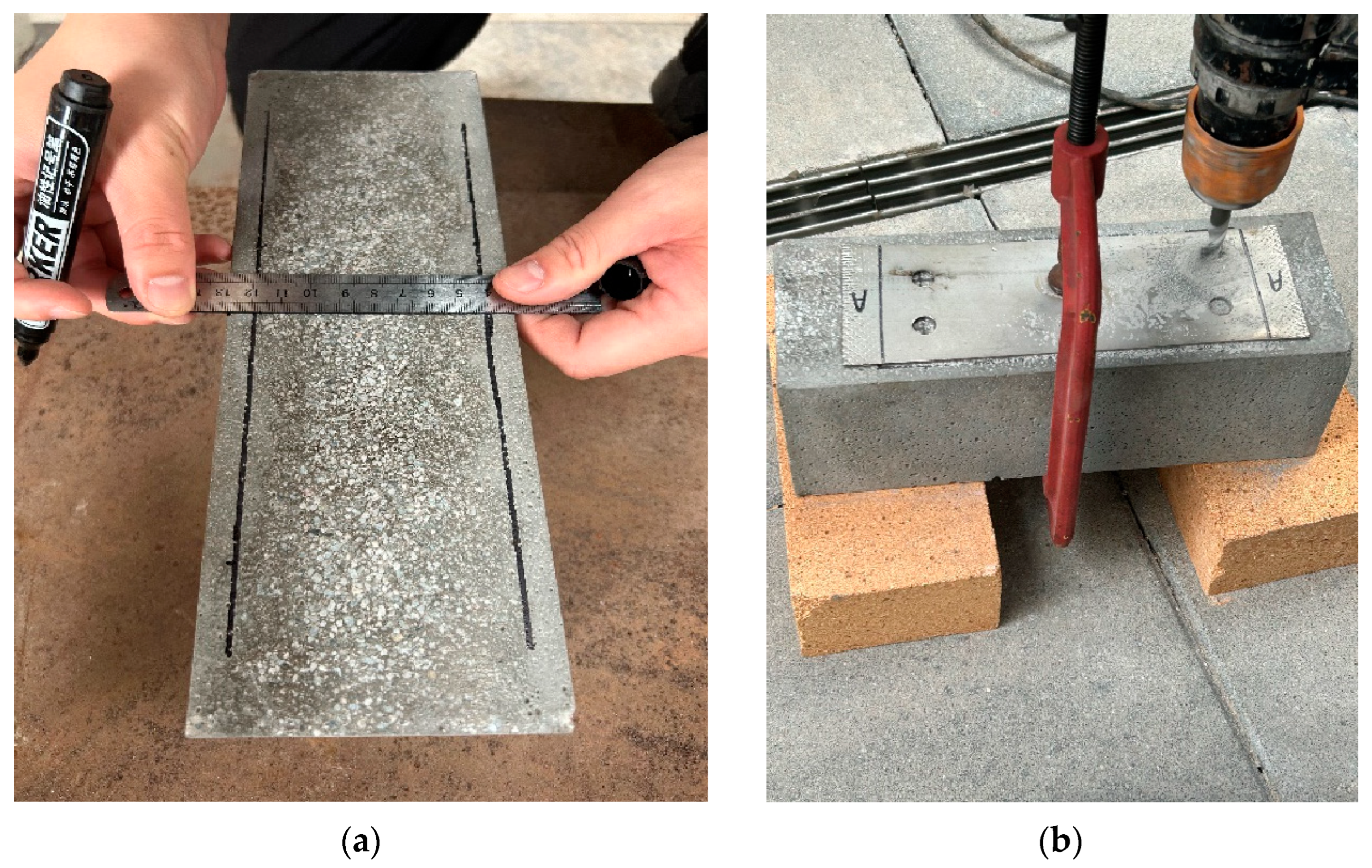
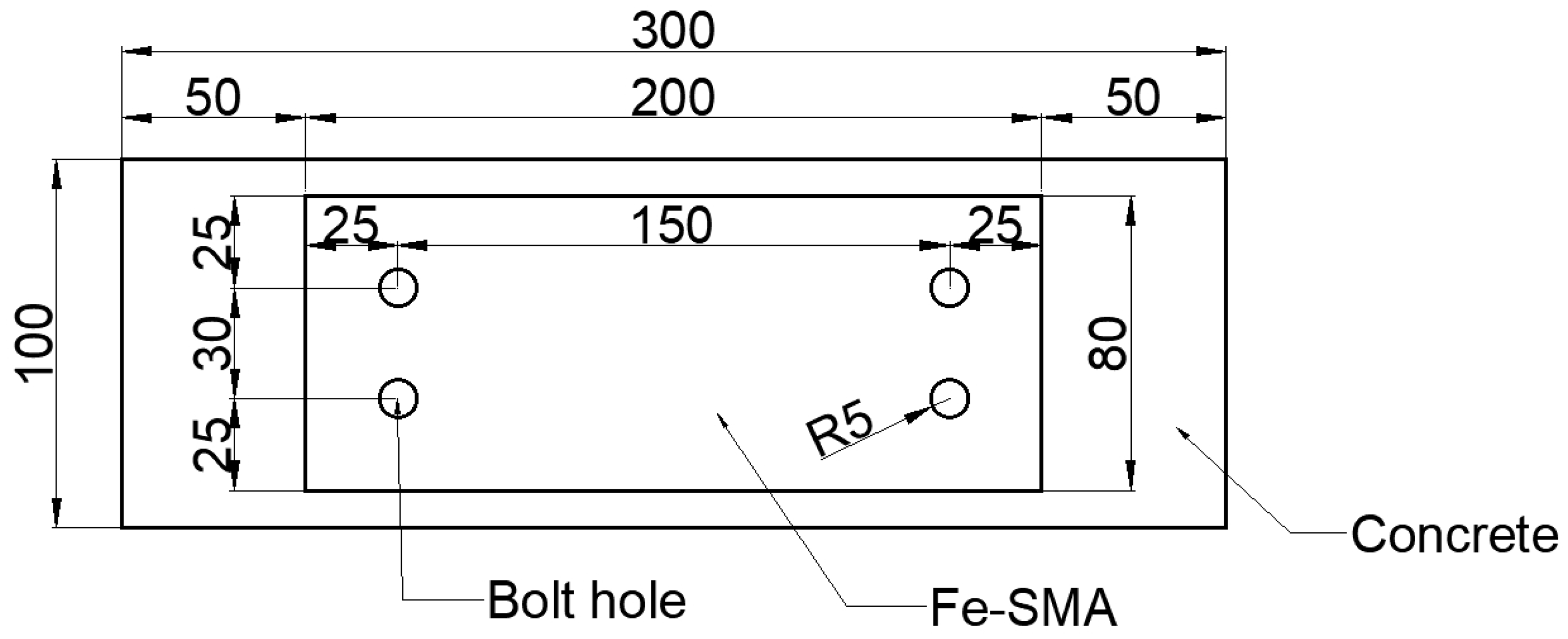
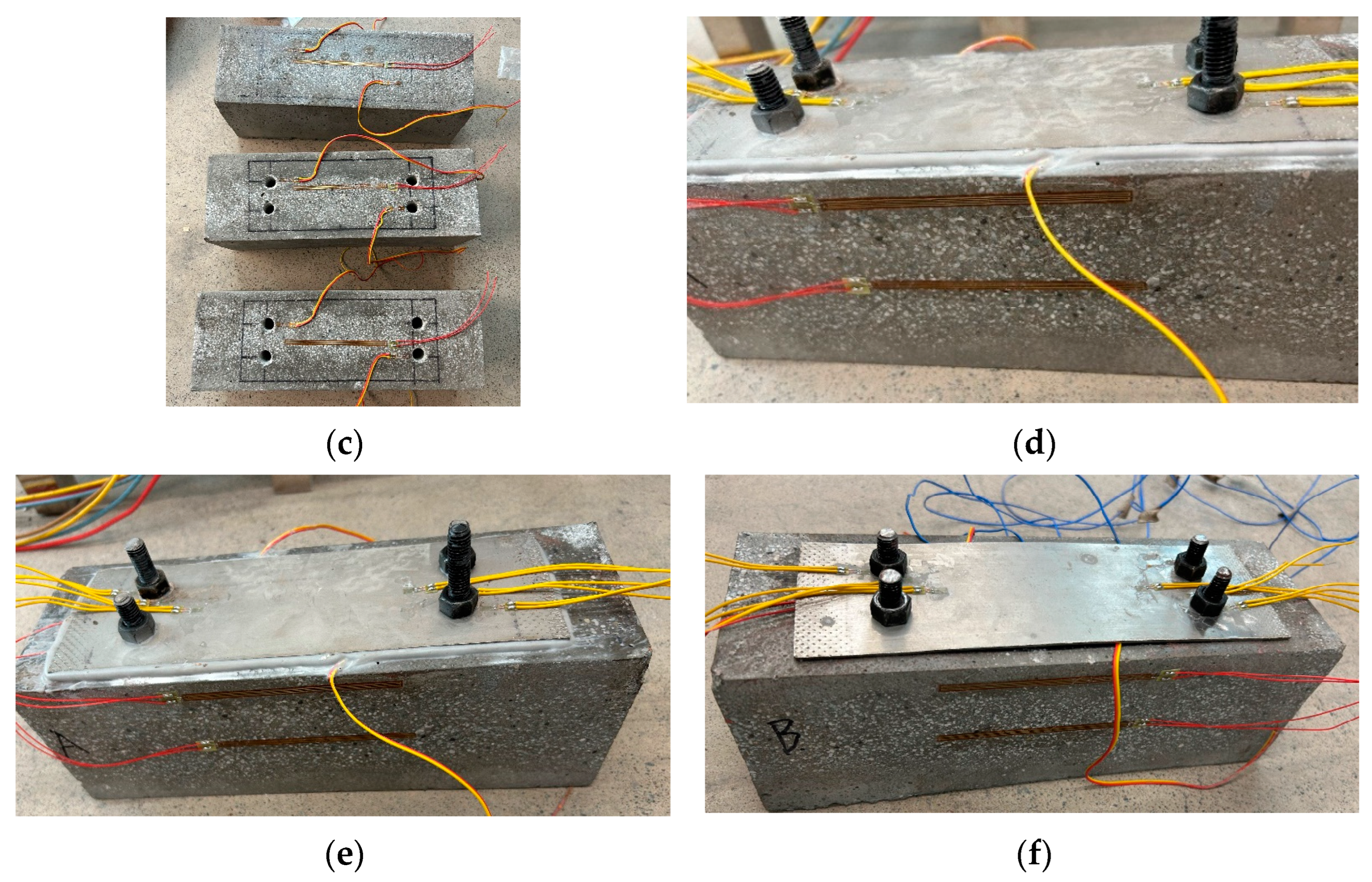
2.1. Test Specimens

Concrete specimens with dimensions of 300 mm × 100 mm × 100 mm are poured using C50 grade concrete. The concrete surface is polished using a sanding machine, and then the surface is wiped with alcohol. Fe-SMA plates with a length of 200 mm, a width of 80 mm and a thickness of 2 mm are used. As shown in Figure 1, the Fe-SMA plate connection area is located on the concrete surface, and holes are drilled at the predetermined positions of the concrete specimens using a bolted connection and an adhesive–bolted hybrid connection, with a diameter of 10 mm and a depth of 50 mm. The arrangement of bolt holes is shown in Figure 2.
As shown in Figure 3, an MTS tensile testing machine is used to conduct pretensile testing on Fe-SMA plates. To achieve the goal of restoring stress, based on existing experimental data [13], the total tensile strain is set to 4%. After stretching, holes are drilled with a diameter of 10 mm at both ends of the Fe-SMA plate according to the preset position.
Three types of connection methods, including adhesive–bolted hybrid connection, bolted connection and adhesively bonded connection, are used to fix the Fe-SMA plates on the surface of the concrete specimens. Among them, for bolted connection specimen, it is necessary to inject reinforcement glue into the anchor bolt holes to reduce the deformation of the Fe-SMA plate during the activation process and minimize the loss of prestress. For the adhesively bonded connection specimen, after applying the structural adhesive evenly, pressure curing is required to ensure that the adhesive fully exerts its bonding performance after solidification. For the adhesive–bolted hybrid connection specimen, it is necessary to inject reinforcement glue into the anchor bolt holes and apply structural adhesive for pressure curing. Finally, the reinforced specimens with strain gauges arranged are shown in Figure 4, where the adhesive–bolted hybrid connection specimen is numbered as Con-1, the bolted connection specimen is numbered as Con-2, and the adhesively bonded connection specimen is numbered as Con-3.

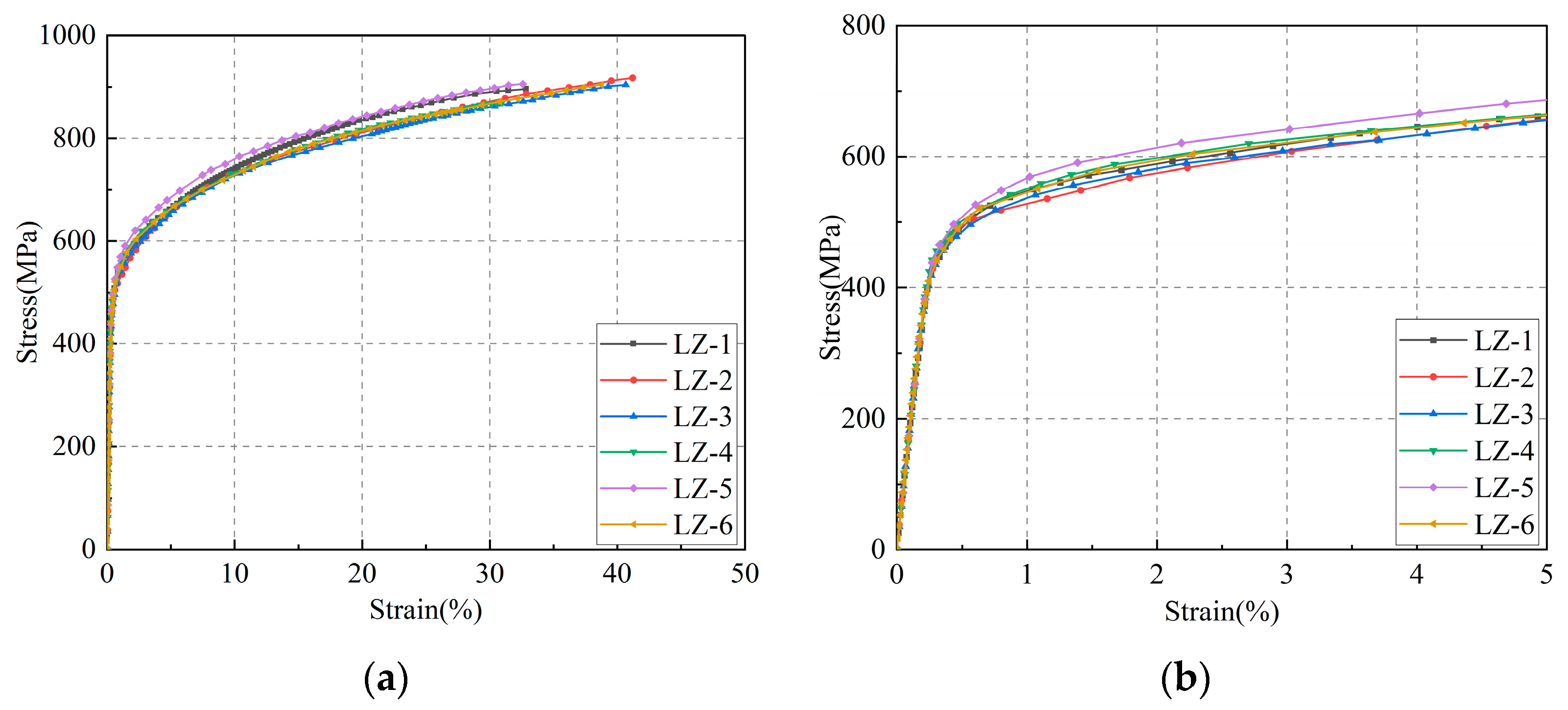
2.2. Mechanical Properties of Materials

For the Fe-SMA plates used in the experiment, a tensile test was conducted to obtain its mechanical properties. According to the experimental results, the elastic modulus of the Fe-SMA is 166 GPa, the yield strength is 490 MPa and the tensile strength is 894 MPa. The independently developed heat-resistant structural adhesive is employed, featuring epoxy resin as the material, with a high glass transition temperature of 85 °C. The stress–strain curve of the Fe-SMA is shown in Figure 5. Additionally, mechanical tests were conducted on the concrete and structural adhesive used in the experiment, and the anchor bolt used in the experiment was Grade 8.8 high-strength bolt. The mechanical properties of materials are shown in Table 1.

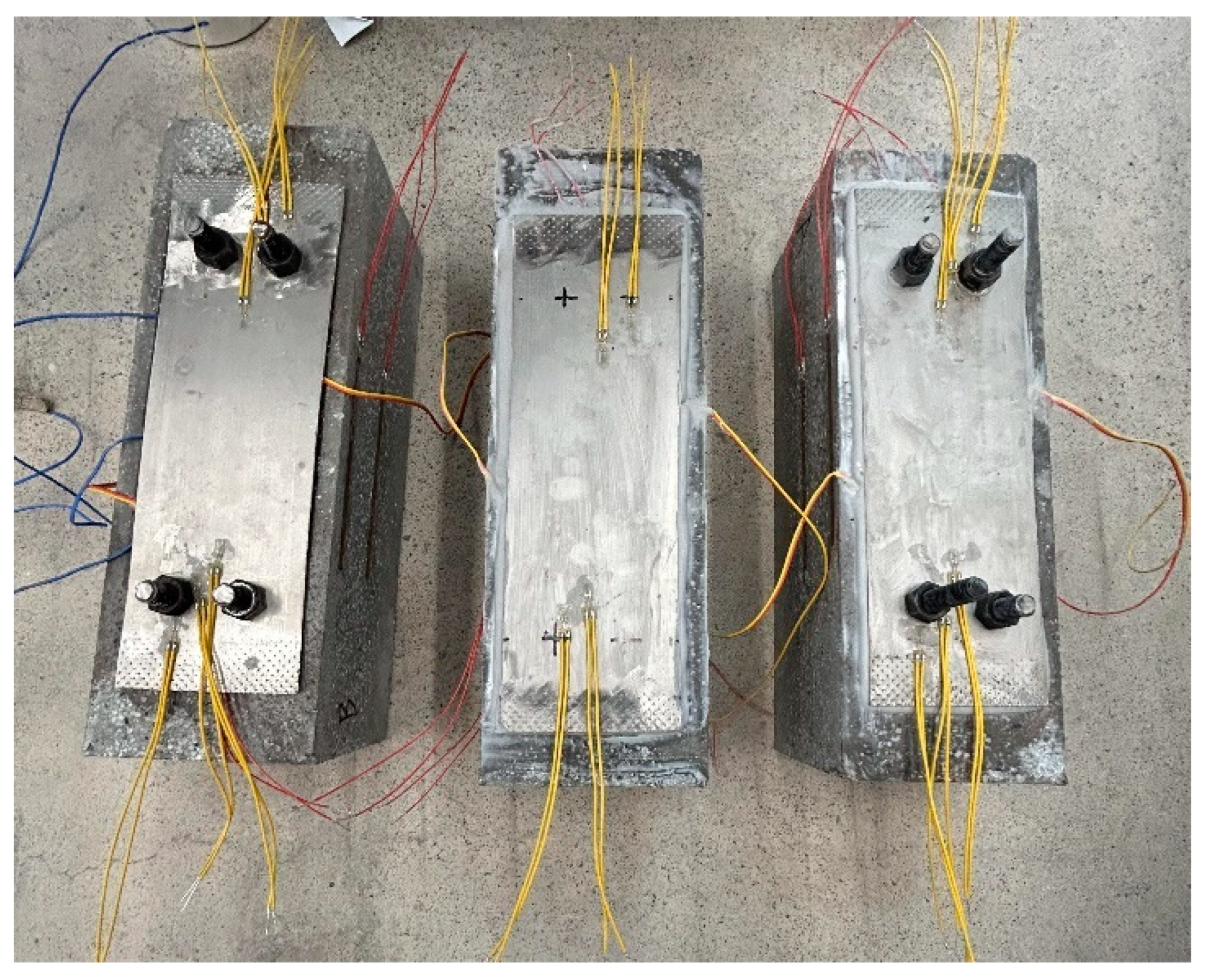
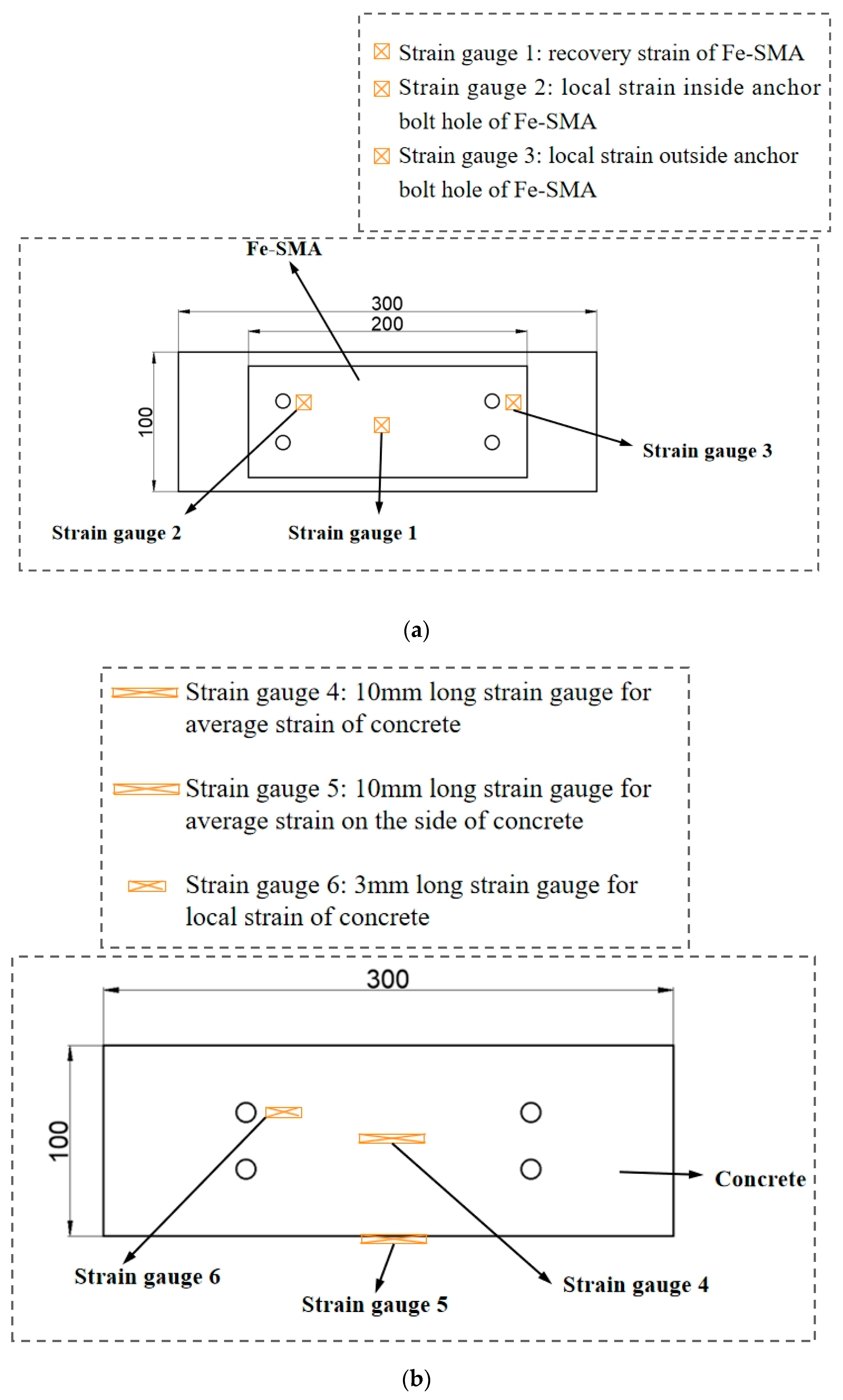
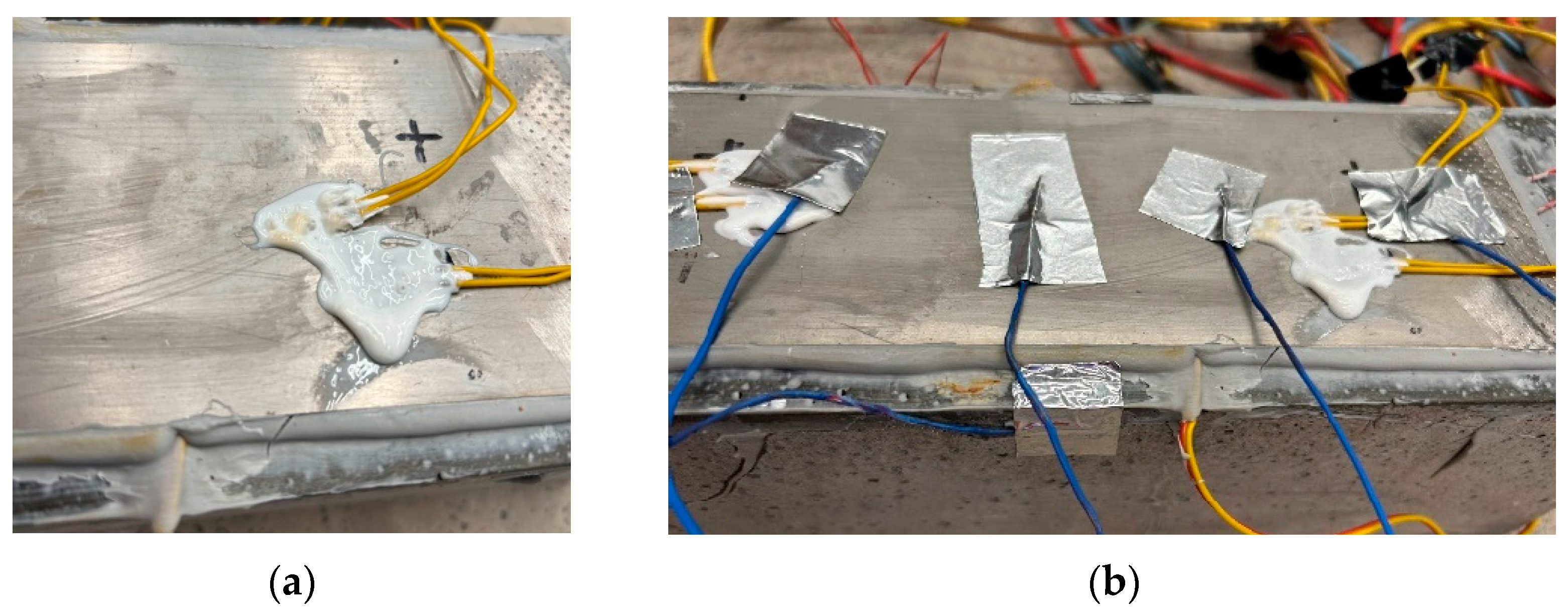
2.3. Measurement Scheme

The arrangement of strain gauges is shown in Figure 6.
(1)
Strain gauges are arranged at the activation boundary of the Fe-SMA plate to determine the magnitude of the recovery strain during the activation process.
(2)
In order to monitor the local strain inside and outside the anchor bolt holes of the Fe-SMA plate during the activation process, strain gauges are arranged on the inner side of the Fe-SMA plate holes and the outer side of the Fe-SMA plate, respectively.
(3)
In order to measure the average stress on the surface of the concrete during the activation process, a strain gauge of 10 mm in length is attached to the surface of the concrete.
(4)
To determine the average strain inside the concrete during the activation process, a strain gauge of 10 mm in length is attached to the side of the specimens at a distance of 10 mm from the upper surface.
(5)
To determine the local stress near the anchor bolt holes during the activation process, a strain gauge of 3 mm in length is attached to the concrete surface 5 mm away from the inner side of the anchor bolt holes.

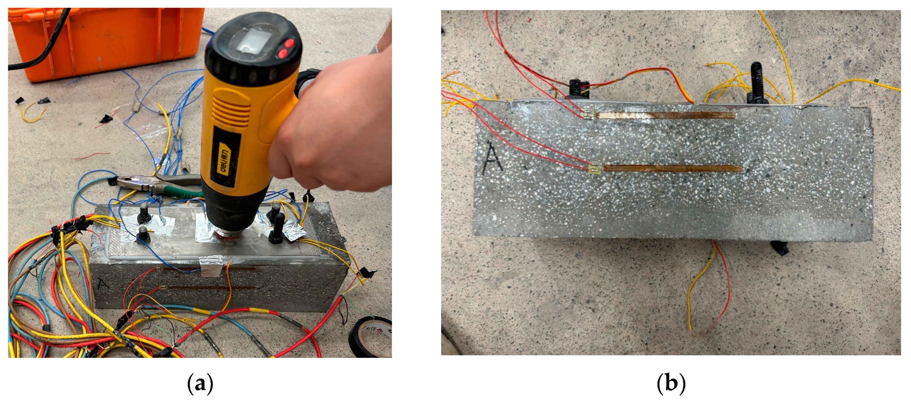
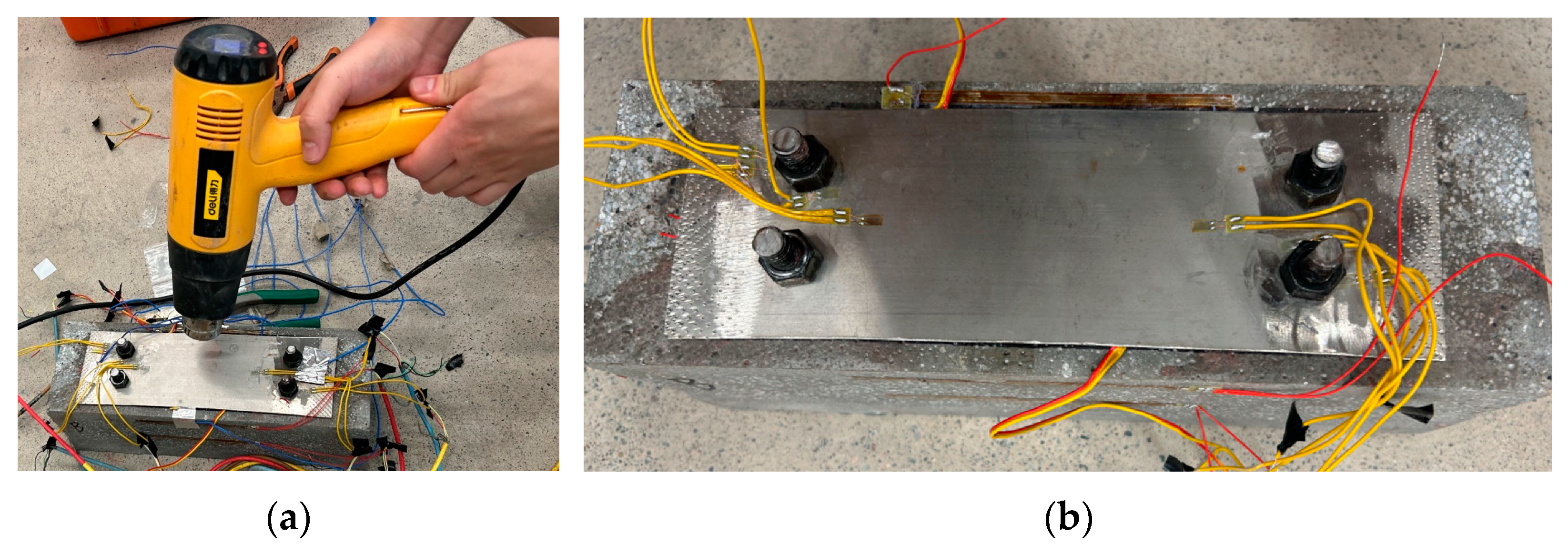
2.4. Activation Process

As high temperatures cause softening of the structural adhesive, degradation of the adhesive will directly impact the ultimate reinforcement effect. Therefore, conducting Fe-SMA activation tests at high temperatures and monitoring the temperature during the activation process is of significant importance. After preparation of the test specimens, high-temperature activation tests are carried out after three days of pressure curing. Before heat activation, four temperature measuring points are arranged at both ends of the concrete anchor bolt hole and on the upper side. Three temperature measurement points are arranged outside and in the center of the activation area of the Fe-SMA plate to monitor the temperature of the specimens during the activation process. The high-temperature activation experimental device is shown in Figure 7. The activation area of the Fe-SMA plate is heated using a hot air gun, and the temperature changes displayed at the temperature measurement points in the activation area are monitored in real time. The activation temperature of the Fe-SMA plate reaches 250 °C and is maintained for 1 min. The entire heat activation process lasts for ten minutes.
For the specimen Con-1, no significant phenomenon is observed during the heat activation process when the activation temperature is below 120 °C. When the activation temperature exceeds 120 °C, slight shrinkage can be observed in the Fe-SMA plate. At the same time, an increase in strain can be observed in both the Fe-SMA plate and the concrete. As the activation temperature further increases, the strain growth rate accelerates. During the cooling process, the strain growth rate of Fe-SMA further accelerates. As the temperature decreases, the internal prestress of the reinforced concrete specimens further increases, and the overall anchorage is good. The specimen Con-1 is not damaged during the reinforcement process. The reinforcement process is shown in Figure 8.
For the specimen Con-2 connected by anchor bolts, the activation process is shown in Figure 9. During the heat activation process, no significant phenomenon is observed in the Fe-SMA plate when the activation temperature is below 120 °C. When the activation temperature exceeds 120 °C, a significant increase in local strain is detected at the Fe-SMA plate and concrete anchor bolt holes, and the strain growth rate accelerates with a further increase in activation temperature. During the cooling process, the strain growth rate of the Fe-SMA further accelerates. As the temperature decreases, the stress of the reinforced concrete specimen near the anchor bolt hole further increases, and the local compressive stress of the concrete near the anchor bolt hole is much greater than that of the other two specimens. Throughout the entire heat activation process, the anchor bolts are securely anchored and there are no adverse changes observed.
For specimen Con-3 connected by the structural adhesive, the activation process is shown in Figure 10. During the heat activation process, no obvious phenomenon is observed when the activation temperature is below 120 °C. When the activation temperature exceeds 120 °C, it can be observed that the Fe-SMA plate shrinks, and as the activation temperature further increases, the strain growth rate accelerates. When the activation temperature reaches around 200 °C, partial softening of the structural adhesive is observed, and at the same time, significant slip occurs in the Fe-SMA plate. It is also observed that the strain growth rate of the Fe-SMA plate is slow, which is due to the slip of the structural adhesive layer causing shrinkage of the Fe-SMA plate, thereby reducing the generation of recovery stress during the activation process. During the cooling process, the strain of the Fe-SMA further increases, and the overall experimental process shows good bonding between the Fe-SMA plate and the concrete block without adverse phenomena. Ultimately, the strain of the Fe-SMA plate in specimen Con-3 is smaller compared to specimen Con-1 and specimen Con-2. This result is mainly due to the influence of slip and softening of the structural adhesive layer.
The specimen after activation and reinforcement is shown in Figure 11.

3. Test Results and Discussion
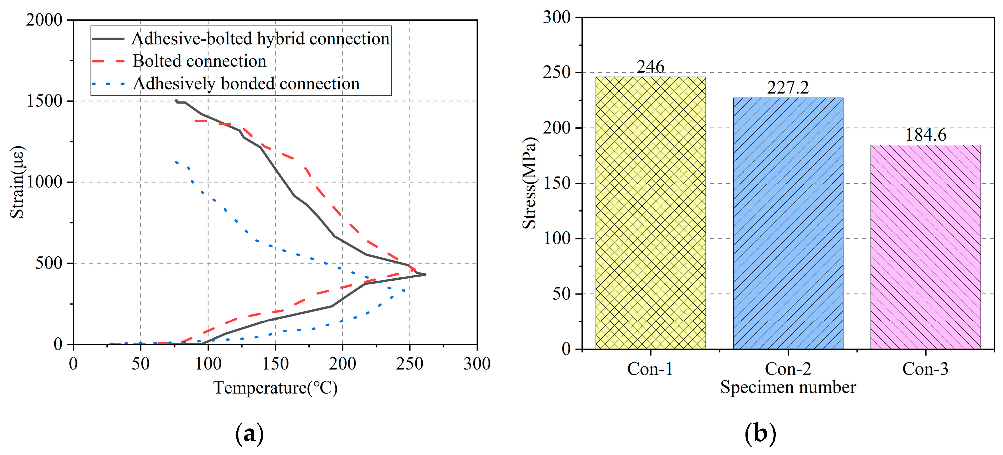
The final stress after activation of Fe-SMA plates is shown in Table 2.

3.1. Fe-SMA Stress

Figure 12 shows the trend in strain variation with temperature at the boundary between the activated and non activated regions of the Fe-SMA plate (strain gauge 1) during elevated-temperature activation. The reason for selecting the strain measurement at the boundary is that the activation region cannot accurately monitor the strain in the Fe-SMA due to the elevated temperatures involved. It can be observed that the strain of the Fe-SMA does not change significantly when the temperature is below 100 °C. When the activation temperature exceeds 100 °C, the strain of the Fe-SMA begins to increase, and the growth rate gradually increases. After the activation temperature reaches 250 °C, the temperature begins to decrease. During the cooling process, the strain further increases. It can be found that compared with the heating process, the strain of the Fe-SMA increases more during the cooling process, which further confirms that the metallographic phase transformation of the Fe-SMA is mainly concentrated in the cooling process after temperature activation.
The magnitude of the recovery stress of Fe-SMA plates in different connection methods is calculated according to Equation (1). Among them, the elastic modulus of the Fe-SMA ( E S M A ) is shown in Table 1.
σ S M A = E S M A × ϵ
Finally, as shown in Figure 12, the recovery stress of the Fe-SMA in the adhesive–bolted hybrid connection is 246 MPa, the recovery stress of the Fe-SMA in the bolted connection is 227.2 MPa and the recovery stress of the Fe-SMA in the adhesively bonded connection is 184.6 MPa. The recovery stress of the Fe-SMA in the adhesively bonded connection is smaller compared to the other two connection methods, because the softening and slip of the structural adhesive during the activation process reduce the total recovery force.

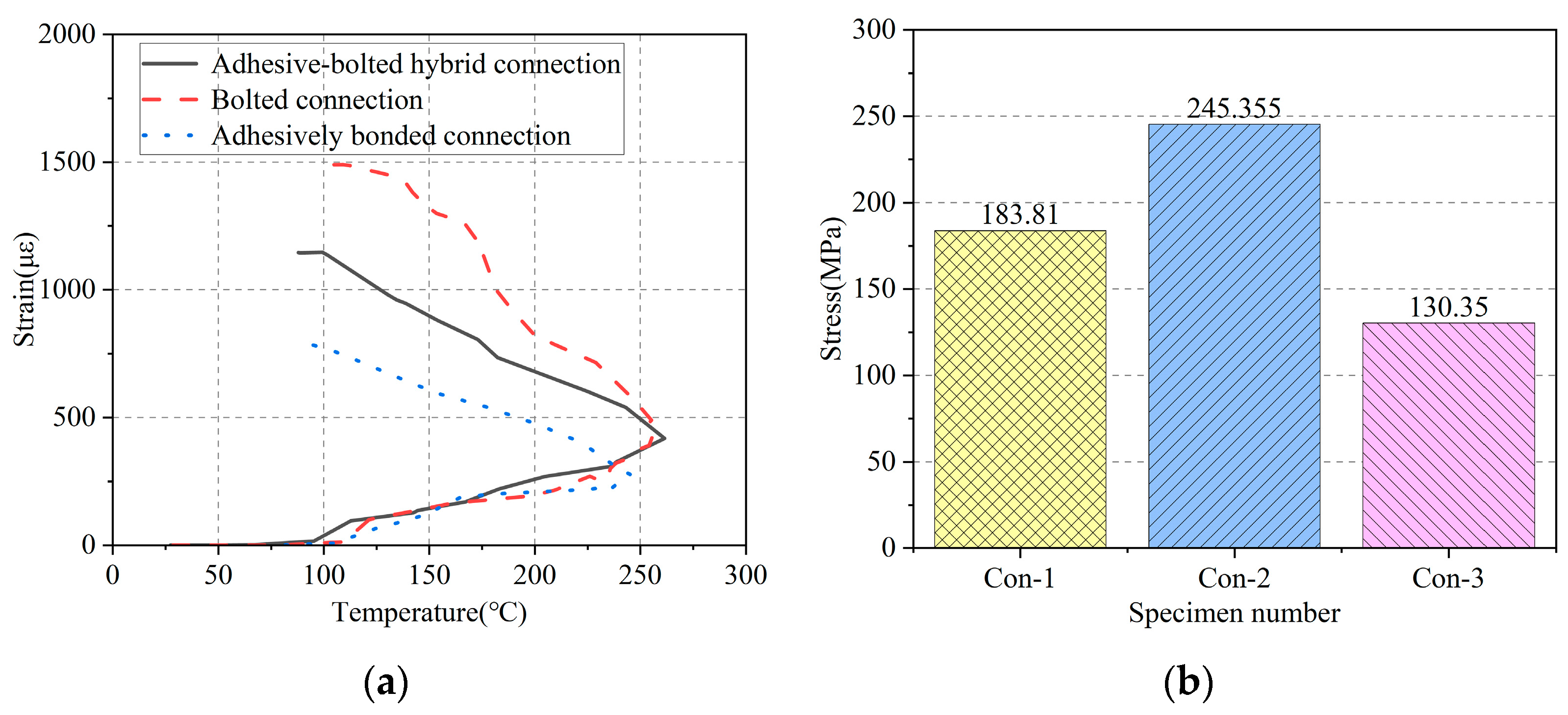
3.2. Local Stress inside the Anchor Hole of Fe-SMA Plates

Figure 13 shows the recovery strain inside the Fe-SMA anchor bolt hole (strain gauge 2) during the activation process. It can be observed that the overall trend in local strain at the Fe-SMA plate anchor bolt hole is that the growth rate and increment are greater during the cooling process. Finally, the local stress inside the Fe-SMA anchor bolt hole in the adhesive–bolted hybrid connection is 183.81 MPa, the local stress of the Fe-SMA in the bolted connection is 245.36 MPa and the local stress of the Fe-SMA in the adhesively bonded connection is 130.35 MPa. However, in addition to the decrease in recovery strain caused by slip and softening of the structural adhesive, the strain at the inside of the anchor bolt hole is highest in the bolted connection, followed by the adhesive–bolted hybrid connection, and lowest in the adhesively bonded connection. The local stress of the Fe-SMA in the adhesively bonded connection is significantly lower than the other two connection methods. This is due to the stress concentration problem near the anchor bolt hole. Therefore, in the condition of similar total strain in the Fe-SMA, the strain at the anchor bolt hole of the adhesive–bolted hybrid connection should be smaller than that of the bolted connection. In the adhesively bonded connection, there is no problem of stress concentration, which also confirms that structural adhesive can effectively alleviate the local stress concentration problem in the anchor bolt holes of the Fe-SMA plate.

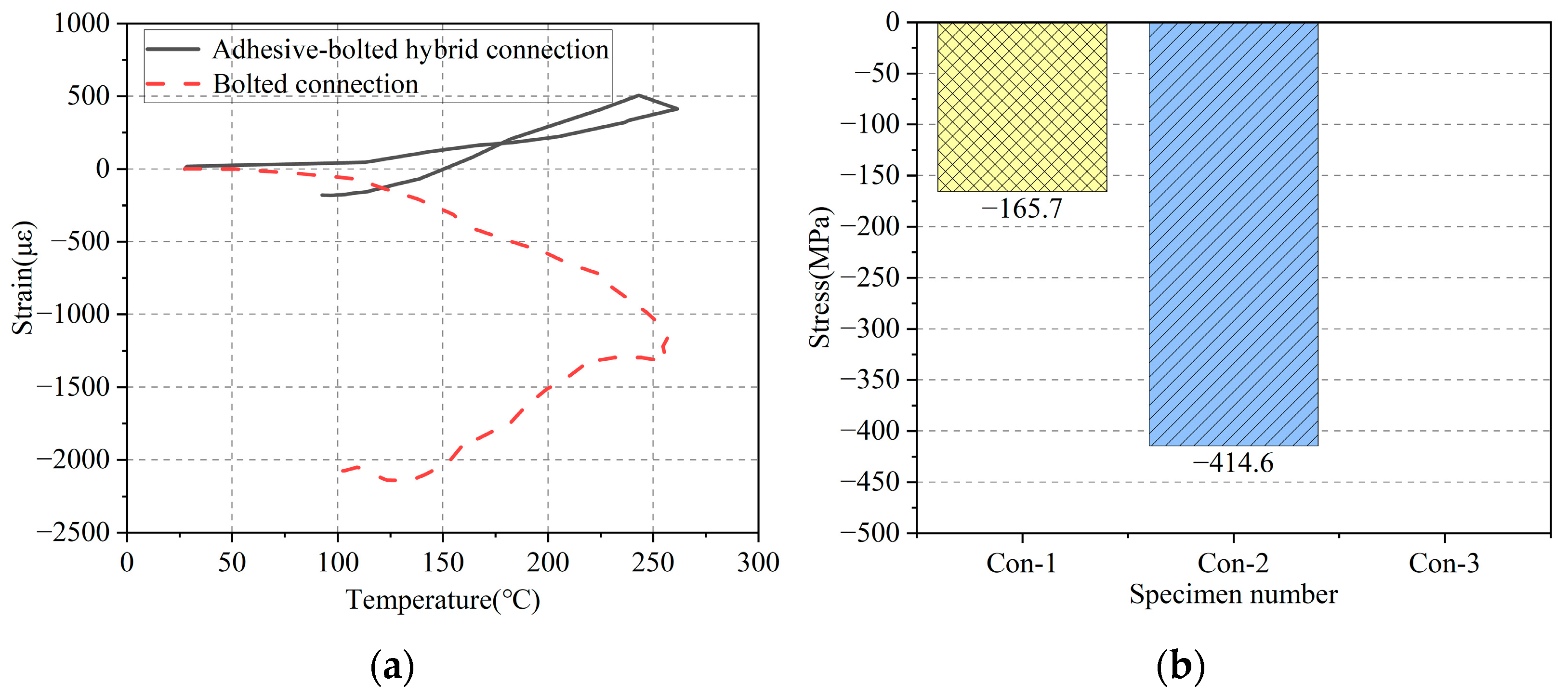
3.3. Local Stress on the Compression Side of Anchor Hole in Fe-SMA Plates

Figure 14 shows the strain–activation temperature curve of Fe-SMA near the outer side (strain gauge 3) of the anchor bolt hole. It can be observed that during the activation process, the strain of the adhesive–bolted hybrid connection is first positive and gradually increases. As Fe-SMA is further activated, the strain begins to decrease and gradually becomes negative. This is because in the early stage of activation, the strain of the Fe-SMA is relatively small, and in the adhesive–bolted hybrid connection, the structural adhesive mainly bears the shear force, while the Fe-SMA on the outer side of the anchor bolt is subjected to tensile force. As the total strain of the Fe-SMA further increases, the structural adhesive’s load-bearing capacity becomes insufficient, and the anchor bolts begin to bear shear forces. The Fe-SMA outside the anchor bolt hole begins to receive compression from the anchor bolts, exhibiting compressive strain. The strain of the Fe-SMA at the anchor bolt hole in the bolted connection is initially compressive strain with activation of the Fe-SMA and gradually increases, with a maximum compressive strain of 0.0024, further confirming the local stress concentration problem of the Fe-SMA in the bolted connection.

3.4. Surface Strain and Stress of Concrete Specimen

After the reinforcement is completed, the prestress at each point of the concrete is shown in Table 3.
Although the stress–strain relationship of concrete is not completely linear elastic [38], considering that the strain of concrete during the test is within the elastic range, a simplified calculation equation within the linear elastic range is adopted herein. The magnitude of the prestress on concrete specimens in different connection methods is calculated according to Equation (2), where the elastic modulus of concrete ( E C o n ) is shown in Table 1.
σ C o n = E C o n × ϵ
Figure 15 shows the variation in the average strain on the surface of the concrete (strain gauge 4) with the activation temperature during the activation process. Corresponding to the activation recovery stress of Fe-SMA, during the heat activation stage, the recovery stress of Fe-SMA is relatively small, and the effect of the prestress on the concrete is not significant. During the activation cooling stage, due to the greater increase in recovery stress of Fe-SMA, the average prestress on the surface of the concrete also further increases. Overall, the average prestress on the surface of the concrete is highest for the adhesive–bolted hybrid connection, reaching −19.3 MPa, slightly lower for the adhesively bonded connection, reaching −15.3 MPa, and lowest for the bolted connection, reaching −13.2 MPa. Although the softening and slip of the adhesively bonded connection during activation lead to a decrease in the recovery stress of Fe-SMA, the adhesively bonded connection method has a better effect on the preloading stress of the concrete surface compared to the bolted connection. For engineering requirements that require prestress to be applied to the surface of concrete, such as closing cracks on the concrete surface, the use of adhesively bonded connections for structural reinforcement is more effective.

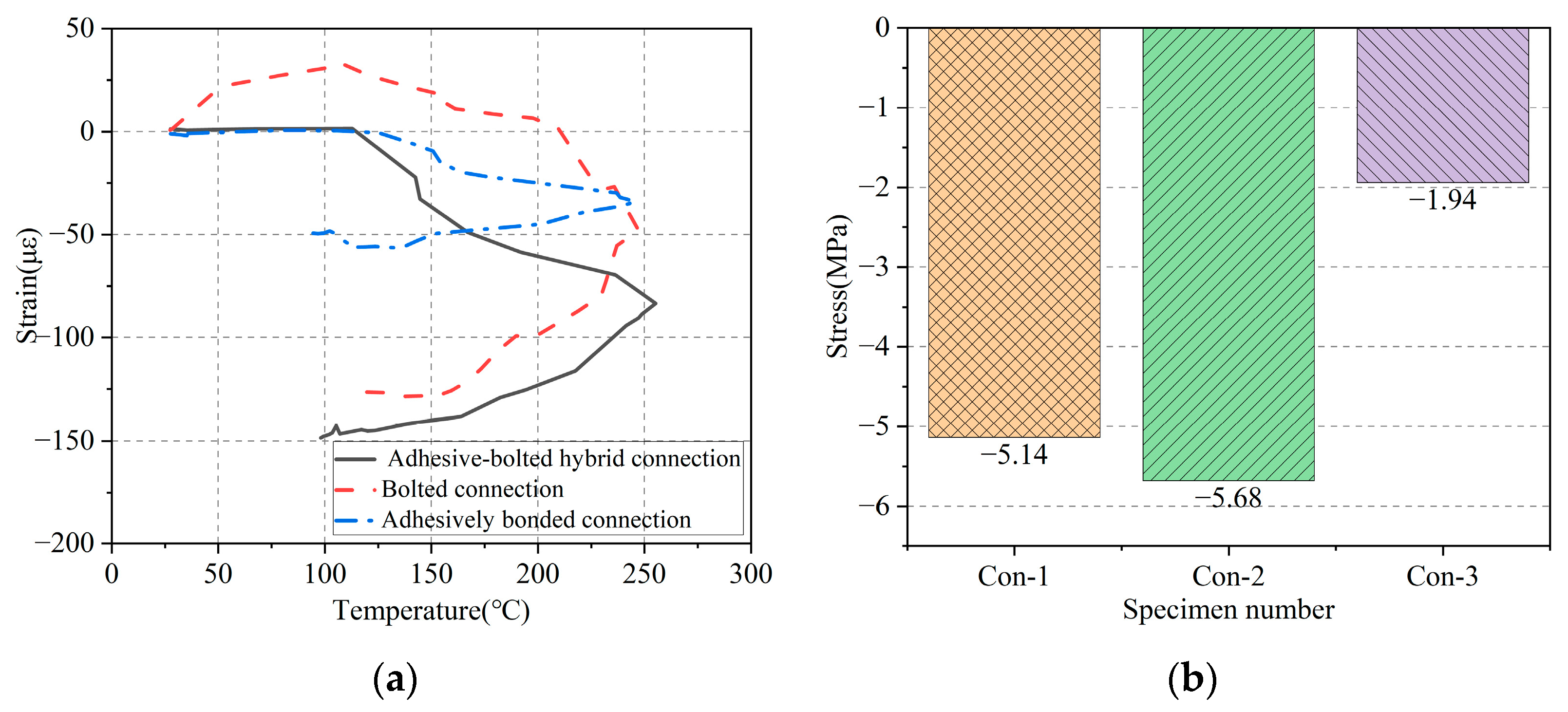
3.5. Strain and Stress of Concrete Specimen on Side Surface

To investigate the effect of surface bonding reinforcement on the internal stress of the concrete specimen, strain gauges are attached to the side of the specimens at a distance of 10 mm from the upper surface, and the average strain (strain gauge 5) of the concrete at this location is measured. As is shown in Figure 16, the result shows that after reinforcement, the prestress on the concrete at the measuring point is highest for the bolted connection, which is −5.68 MPa. The adhesive–bolted hybrid connection is close to the bolted connection, which is −5.14 MPa, and the adhesively bonded connection is the smallest, which is −1.94 MPa. The concrete stress of the adhesively bonded connection is significantly lower than the other two connection methods. One part is due to the softening and slip during the activation process of the structural adhesive, which leads to a decrease in the restoring force, while the other part is due to the weaker influence of the structural adhesive on the concrete bonding surface below, which is not as effective as the connection method of the bolted connection.

3.6. Strain and Stress at Concrete Anchor Hole

Figure 17 shows the local strain changes in the concrete near the anchor bolt hole (strain gauge 6) during the activation process. Similar to the trend in the local stress changes around the Fe-SMA hole, during the activation process, the local stress near the concrete anchor bolt hole increases during the heat activation stage, but the local stress is greater during the activation cooling stage. Additionally, the local stress around the concrete hole in the bolted connection is the highest, reaching −46.3 MPa. The local stress around the anchor bolt hole in the adhesive–bolted hybrid connection decreases to −34.8 MPa, while the local stress around the hole in the adhesively bonded connection is the lowest, at −17.8 MPa. It can be observed that there is a problem of local stress concentration near the concrete anchor bolt hole in the bolted connection, while there is no problem of local stress concentration in the adhesively bonded connection. The combination use of anchor and adhesive effectively alleviates the problem of local compression in concrete.

4. Conclusions

This paper conducts experiments on the active reinforcement of concrete structures with an Fe-SMA with various connecting methods, focusing on their influence on the recovery stress and reinforcement effect. The obtained conclusions are as follows:
  • During the activation process of an Fe-SMA, the recovery force generated during the heating stage is relatively small, while the recovery force increases significantly during the cooling stage. When the activation temperature of the Fe-SMA reaches 250 °C, the recovery stress in the adhesive–bolted hybrid connection reaches 246 MPa, which is sufficient for structural reinforcement of concrete structures.
  • In the adhesive–bolted hybrid connection, the average prestress on the reinforced surface of the concrete specimen reaches −19.3 MPa, achieving good reinforcement effect to apply compression.
  • A simple bolted connection can lead to local stress concentrated in the concrete block and Fe-SMA plate around the hole, which can easily cause early cracking of the concrete. The adhesively bonded connection can effectively avoid this problem, so the application of a structural adhesive in the adhesive–bolted hybrid connection significantly alleviates the stress concentration phenomenon.
  • A simple adhesively bonded connection is prone to softening and slip of the structural adhesive during the activation process, which reduces the overall restoring force, hence having adverse effects on the structural reinforcement. Additionally, the low glass transition temperature characteristic of adhesive affects the performance of the connection between the Fe-SMA and concrete. Optimizing the performance of the structural adhesive is of great significance in practical applications. However, structural adhesive has a superior effect on applying even prestress on the surface of concrete and can be used for repairing cracks in concrete structures. In addition, the bonded connection avoids damage caused by openings in the parent structure, which can be effectively applied in the non-destructive reinforcement of structures.
  • The adhesive–bolted hybrid connection effectively combines the advantages of adhesively bonded connection and bolted connection. The experimental results show that the adhesive–bolted hybrid connection effectively reduces the local stress concentration problem of the concrete and Fe-SMA at the anchor bolt hole, while avoiding the prestress loss caused by the softening and slip of structural adhesive during elevated-temperature activation, achieving an ideal reinforcement effect.
  • Compared to the bolted connection and adhesively bonded connection, in adhesive–bolted hybrid connections, the Fe-SMA can bring greater local prestress to concrete structures and have a better effect in suppressing the further expansion of shear cracks in concrete structures.
  • The experimental findings not only provide test support for the application of Fe-SMAs in reinforcing concrete structures but also offer new perspectives for future research. Future studies could further optimize the reinforcement effectiveness of Fe-SMAs in concrete structures.

Author Contributions

Conceptualization, X.Q. and X.J.; methodology, X.Q. and X.J.; software, D.Z.; investigation, D.Z.; data curation, X.Q.; writing—original draft preparation, D.Z. and Y.W.; writing—review and editing, X.Q. and X.J.; visualization, D.Z.; supervision, X.J.; project administration, X.Q. and X.J.; funding acquisition, X.Q. All authors have read and agreed to the published version of the manuscript.

Funding

This research was funded by the Natural Science Foundation of China [Grant No. 52278207, 52278206] and National Key R&D Program of China [Grant No. 2020YFD1100403].

Institutional Review Board Statement

Not applicable.

Informed Consent Statement

Not applicable.

Data Availability Statement

The raw data supporting the conclusions of this article will be made available by the authors on request.

Conflicts of Interest

The authors declare no conflicts of interest.

References

  1. George, S.; Thenmozhi, R.; Magudeswaran, P.N. Study on corrosion of activated fly ash concrete beams. Asian J. Chem. 2012, 24, 5142–5144. [Google Scholar]
  2. Jin, L.; Xia, H.; Jiang, X.; Du, X. Size effect on shear failure of CFRP-strengthened concrete beams without web reinforcement: Meso-scale simulation and formulation. Compos. Struct. 2020, 236, 111895. [Google Scholar] [CrossRef]
  3. Gusella, F.; Orlando, M. Failure analysis and retrofitting of reinforced concrete beams in existing moment resisting frames. Eng. Fail. Anal. 2023, 153, 107601. [Google Scholar] [CrossRef]
  4. Foraboschi, P. Bending load-carrying capacity of reinforced concrete beams subjected to premature failure. Materials 2019, 12, 3085. [Google Scholar] [CrossRef] [PubMed]
  5. Jafarzadeh, H.; Nematzadeh, M. Flexural strengthening of fire-damaged GFRP-reinforced concrete beams using CFRP sheet: Experimental and analytical study. Compos. Struct. 2022, 288, 115378. [Google Scholar] [CrossRef]
  6. Xu, X.; He, D.; Zeng, S.; He, W.; Tan, H.; Yu, Z. Effect of concrete cracks on the corrosin of headed studs in steel and concrete composite structures. Constr. Build. Mater. 2021, 293, 123440. [Google Scholar] [CrossRef]
  7. Xu, Y.; Huang, J. Cyclic performance of corroded reinforced concrete short columns strengthened using carbon fiber-reinforced polymer. Constr. Build. Mater. 2020, 247, 118548. [Google Scholar] [CrossRef]
  8. Teng, J.; Yu, T.; Fernando, D. Strengthening of steel structures with fiber-reinforced polymer composites (Review). J. Constr. Steel. Res. 2012, 78, 131–143. [Google Scholar] [CrossRef]
  9. Rodrigues, H.; Arede, A.; Furtado, A.; Rocha, P. Seismic behavior of strengthened RC columns under biaxial loading: An experimental characterization. Construct. Build. Mater. 2015, 95, 393–405. [Google Scholar] [CrossRef]
  10. Tan, C.; Jiang, X.; Qiang, X.; Fan, M. Flexural performance of carbon fiber-reinforced polymer prestressed spun high-strength concrete pile. Appl. Sci. 2024, 14, 7170. [Google Scholar] [CrossRef]
  11. Sellitto, A.; Riccio, A. Overview and future advanced engineering applications for morphing surfaces by shape memory alloy materials. Materials 2019, 12, 708. [Google Scholar] [CrossRef] [PubMed]
  12. Cui, D.; Li, H.; Song, G. Progress on study and application of shape memory alloy in civil engineering. J. Disaster. Prev. Mitig. Eng. 2005, 65, 86–94. [Google Scholar]
  13. Qiang, X.; Wang, Y.; Wu, Y.; Jin, P.; Jiang, X. Constitutive model and activation recovery performance of Fe-SMA: Experimental and theoretical study. Construct. Build. Mater. 2024, 420, 135537. [Google Scholar] [CrossRef]
  14. Billah, A.M.; Rahman, J.; Zhang, Q. Shape memory alloys (SMAs) for resilient bridges: A state-of-the-art review. Structures 2022, 37, 514–527. [Google Scholar] [CrossRef]
  15. Mohamed, E.; Ahmed, k.; Mohammad, A.; Raim, H.; Wael, A. Enhancing the shear capacity of RC beams with web openings in shear zones using pre-stressed Fe-SMA bars: Numerical Study. Buildings 2023, 13, 1505. [Google Scholar] [CrossRef]
  16. Cladera, A.; Oller, E.; Ribas, C. Pilot experiences in the application of shape memory alloys in structural concrete. J. Mater. Civ. Eng. 2014, 26, 0000974. [Google Scholar] [CrossRef]
  17. Benito, M.; Antoni, C.; Carlos, R. Experimental study on concrete beams reinforced with pseudoelastic Ni-Ti continuous rectangular spiral reinforcement failing in shear. Eng. Struct. 2016, 127, 759–768. [Google Scholar] [CrossRef]
  18. Lv, Z.; Jiang, X.; Qiang, X. Proactive strengthening of U-rib butt-welded joints in steel bridge decks using adhesively bonded Fe-SMA strips. Eng. Struct. 2024, 301, 117316. [Google Scholar] [CrossRef]
  19. Jani, J.M.; Leary, M.; Subic, A.; Gibson, M.A. A review of shape memory alloy research, applications and opportunities. Mater. Des. 2014, 56, 1078–1113. [Google Scholar] [CrossRef]
  20. Qiang, X.; Wu, Y.; Wang, Y.; Jiang, X. Research progress and applications of Fe-Mn-Si-based shape memory alloys on reinforcing steel and concrete bridges. Appl. Sci. 2023, 13, 3404. [Google Scholar] [CrossRef]
  21. Choi, E.; Mohammadzadeh, B.; Kim, D.; Jeon, J. A new experimental investigation into the effects of reinforcing mortar beams with superelastic SMA fibers on controlling and closing cracks. Compos. Part B Eng. 2018, 137, 140–152. [Google Scholar] [CrossRef]
  22. Cladera, A.; Luis, A.; Montoya-Coronado, G.; Joaquín, R.-P.; Ribas, C. Shear strengthening of slender reinforced concrete T-shaped beams using iron-based shape memory alloy strips. Eng. Struct. 2020, 221, 111018. [Google Scholar] [CrossRef]
  23. Hong, K.; Lee, S.; Yeon, Y.; Jung, K. Flexural response of reinforced concrete beams strengthened with near-surface-mounted Fe-based shape-memory alloy strips. Inter. J. Con. Struct. Mater. 2018, 12, 45. [Google Scholar] [CrossRef]
  24. Rojob, H.; El-Hacha, R. Fatigue performance of RC beams strengthened with self-prestressed iron-based shape memory alloys. Eng. Struct. 2018, 168, 35–43. [Google Scholar] [CrossRef]
  25. Qiang, X.; Chen, L.; Jiang, X.; Dong, H. Experimental study on anchorage and activation performance of Fe-SMA strips for structural reinforcements. Constr. Build. Mater. 2023, 401, 132961. [Google Scholar] [CrossRef]
  26. Hu, F.; Wang, Z. Cyclic behavior of high-strength steel beam-to-column welded flange-bolted web connections. Thin. Wall. Struct. 2024, 201, 111999. [Google Scholar] [CrossRef]
  27. Xu, Q.; Chen, H.; Li, W.; Zheng, S.; Zhang, X. Experimental investigation on seismic behavior of steel welded connections considering the influence of structural forms. Eng. Fail. Anal. 2022, 139, 106499. [Google Scholar] [CrossRef]
  28. Izadi, M.R.; Ghafoori, E.; Shahverdi, M.; Motavalli, M.; Maalek, S. Development of an iron-based shape memory alloy (Fe-SMA) strengthening system for steel plates. Eng. Struct. 2018, 174, 433–446. [Google Scholar] [CrossRef]
  29. Li, L.; Wang, S.; Chatzi, E.; Motavalli, M.; Ghafoori, E. Analysis and design recommendations for structures strengthened by prestressed bonded Fe-SMA. Eng. Struct. 2024, 303, 117513. [Google Scholar] [CrossRef]
  30. Wu, Y.; Qiang, X.; Jiang, X.; Meng, X.; Tang, Y. Experimental study on bonding properties of Fe-SMA-to-steel bonded interface. Eng. Struct. 2024, 306, 117779. [Google Scholar] [CrossRef]
  31. Vůjtěch, J.; Ryjáček, P.; Campos Matos, J.; Ghafoori, E. Iron-based shape memory alloy for strengthening of 113-Year bridge. Eng. Struct. 2021, 248, 113231. [Google Scholar] [CrossRef]
  32. Wang, W.; Hosseini, A.; Ghafoori, E. Experimental study on Fe-SMA-to-steel adhesively bonded interfaces using DIC. Eng. Fract. Mech. 2021, 244, 107553. [Google Scholar] [CrossRef]
  33. Jakobsen, J.; Endelt, B.; Shakibapour, F. Bolted joint method for composite materials using a novel fiber/metal patch as hole reinforcement—Improving both static and fatigue properties. Compos. Part B Eng. 2024, 269, 111105. [Google Scholar] [CrossRef]
  34. Kim, T.; Yoo, J.; Roeder, C.W. Experimental investigation on strength and curling influence of bolted connections in thin-walled carbon steel. Thin. Wall. Struct. 2015, 91, 1–12. [Google Scholar] [CrossRef]
  35. Shu, Y.; Qiang, X.; Jiang, X.; Wang, F. Durability of Fe-SMA/steel single-lap joints exposed to hygrothermal environments. Constr. Build. Mater. 2024, 435, 136861. [Google Scholar] [CrossRef]
  36. Li, L.; Wang, W.; Chatzi, E.; Ghafoori, E. Experimental investigation on debonding behavior of Fe-SMA-to-steel joints. Constr. Build. Mater. 2023, 364, 129857. [Google Scholar] [CrossRef]
  37. Julien, M.; Jose, S.; Rouven, C.; Christoph, C.; Masoud, M. Mechanical performance of cold-curing epoxy adhesives after different mixing and curing procedures. Compos. Part B Eng. 2016, 98, 434–443. [Google Scholar] [CrossRef]
  38. Jirasek, M. Modeling of Fracture and Damage in Quasibrittle Materials. Ph.D. Thesis, Northwestern University, Evanston, IL, USA, 1993. Available online: https://www.proquest.com/dissertations-theses/modeling-fracture-damage-quasibrittle-materials/docview/304059266/se-2?accountid=28839 (accessed on 10 August 2024).
Figure 1. Preparation of specimens: (a) positioning; (b) drilling.
Applsci 14 08800 g001
Figure 2. Arrangement of bolt holes (unit: mm).
Applsci 14 08800 g002
Figure 3. Process for preparing Fe-SMA: (a) tension; (b) drilling.
Applsci 14 08800 g003
Figure 4. Test specimens.
Applsci 14 08800 g004
Figure 5. Stress–strain curve of Fe-SMA: (a) overall; (b) detailed.
Applsci 14 08800 g005
Figure 6. Arrangement of measuring points: (a) strain gauges of Fe-SMA; (b) strain gauges of concrete; (c) strain gauges on the surface of concrete specimen; (d) strain gauges on the side of concrete specimen; (e) strain gauges of Fe-SMA plate in specimen Con-1; (f) strain gauges of Fe-SMA plate in specimen Con-2.
Applsci 14 08800 g006aApplsci 14 08800 g006b
Figure 7. Activation device: (a) activation method; (b) activated surface.
Applsci 14 08800 g007
Figure 8. Activation process of specimen Con-1: (a) overall view; (b) side view.
Applsci 14 08800 g008
Figure 9. Activation process of specimen Con-2: (a) overall view; (b) surface view.
Applsci 14 08800 g009
Figure 10. Activation process of specimen Con-3: (a) detailed activation; (b) surface view.
Applsci 14 08800 g010
Figure 11. Specimens after activation and reinforcement.
Applsci 14 08800 g011
Figure 12. Activation boundary strain and stress of Fe-SMA plate: (a) strain–activation temperature curve; (b) recovery stress.
Applsci 14 08800 g012
Figure 13. Strain and stress inside the anchor bolt hole of Fe-SMA: (a) strain–activation temperature curve; (b) local stress.
Applsci 14 08800 g013
Figure 14. Strain and stress on the compression side of anchor bolt holes in Fe-SMA plates: (a) strain–activation temperature curve; (b) local stress.
Applsci 14 08800 g014
Figure 15. Surface strain and stress of concrete: (a) strain–activation temperature curve; (b) average stress.
Applsci 14 08800 g015
Figure 16. Strain and stress on concrete side surface: (a) strain–activation temperature curve; (b) average stress.
Applsci 14 08800 g016
Figure 17. Strain and stress at concrete anchor hole: (a) strain–activation temperature curve; (b) local stress.
Applsci 14 08800 g017
Table 1. Mechanical properties.
MaterialsAverage Compressive Strength/MPaYield Strength/MPaUltimate Strength/MPaElastic Modulus/GPa
C50 concrete51.7--34.6
Structural adhesive--38.19.4
Bolt-640800205
Fe-SMA-389891171
Table 2. Stress of Fe-SMA.
Anchoring MethodsActivated Boundary Stress/MPaStress outside the Bolt Hole/MPaStress inside the Bolt Hole/MPa
Adhesive–bolted hybrid connection246.02183.81−165.66
Bolted connection227.21245.36−414.65
Adhesively bonded connection184.64130.35-
Table 3. Prestress of concrete.
Anchoring MethodsAverage Stress on Specimen Surface/MPaAverage Stress on Specimen Side Surface/MPaStress at Concrete Anchor Hole/MPa
Adhesive–bolted hybrid connection−19.26−5.14−34.78
Bolted connection−13.23−5.68−46.28
Adhesively bonded connection−15.31−1.94−17.84
Disclaimer/Publisher’s Note: The statements, opinions and data contained in all publications are solely those of the individual author(s) and contributor(s) and not of MDPI and/or the editor(s). MDPI and/or the editor(s) disclaim responsibility for any injury to people or property resulting from any ideas, methods, instructions or products referred to in the content.

