Article

Development of a Low-Cost 3D-Printed Upper Limb Prosthetic Device with Hybrid Actuation for Partial Hand Amputees

by
Florin-Felix Răduică
* and
Ionel Simion
Department of Engineering Graphics and Industrial Design, National University of Science and Technology POLITEHNICA Bucharest, 060042 Bucharest, Romania
*
Author to whom correspondence should be addressed.
Appl. Sci. 2024, 14(19), 8929; https://doi.org/10.3390/app14198929
Submission received: 19 August 2024 / Revised: 19 September 2024 / Accepted: 24 September 2024 / Published: 3 October 2024
(This article belongs to the Section Additive Manufacturing Technologies)

Abstract

:
Assistive technology plays an important role in rehabilitation. Body-powered tools rely on manual movement of the artificial limb while externally powered machines use actuators to induce mobility and return function. Alternatively, some devices incorporate both systems. In the case of below-the-wrist amputation, availability of such prosthetics is quite limited according to the literature. Our aim was to establish an alternative design for a partial hand prosthetic with both body and external power. A mixed actuation system was conceived. To generate the grasping force required to impel the transitional partial hand prosthetic, three DC motors were used. As a result, a grasping force of 2.8 kgf was possible to achieve at a 600 mA drawn current at 6 V. Furthermore, a locking system and a pretension system were included to enhance device handling. The resulting device came at a calculated cost of 260 euros. The proposed design provides a solution for patients with below the wrist partial hand amputation.

1. Introduction

During the past 20 years, the prosthetics field has experienced the integration of 3D printing into device design. The high potential of the additive manufacturing (AM) technology promises reduced production time and increased customization levels. Many open-source design projects are available to patients that require a transitional device.
The ongoing advancement of AM research [1] has led to an increase in the number of prosthetic prototypes as first described in [2] and more recently in [3]. Active, body-powered (BP) prosthetics offer some functionality as compared to passive devices. This type of device is usually cable-driven. The low number of parts, 3D-printable components, and use of accessible materials can lead to a low-cost design. Some consideration to finger mechanism designs has to be given to assure different grasping types [4,5] for the case of externally powered (EP) devices. Some research efforts such as the study of Zuniga [6] proposes a transitional low-cost prosthetic device with good acceptance, the device is available only as body-powered. The patients with weak wrists may have limited function gain. In the case of the Flexy Hand 2 [7], weak-wrist participants are considered but the grip of the device is lower than that of the Cyborg Beast. Although much work has been carried out to date, more studies need to be conducted to increase the functionality of 3D-printed low-cost transitional partial hand prosthetics.
The purpose of this study is to develop a device with mixed actuation for people with partial hand amputation at a low cost. The case of below-the-wrist amputation was considered. Availability of such prosthetics is quite limited according to the literature. A prosthetic device with a mixed actuation system was conceived as a solution to the problem of below-the-wrist amputation. To actuate the transitional partial hand prosthetic, three DC motors were used. As a result, a grasping force of 2.8 kgf was possible to achieve at a 600 mA drawn current at 6 V. The device cost was calculated at 260 euros per unit, making it a low-cost solution. Furthermore, a locking system and a pretension system were included to enhance device handling. The proposed design provides a solution for patients with below-the-wrist hand amputation.
In the subsequent sections, the development of a 3D-printed upper limb prosthetic device for partial hand amputees is discussed. In Section 2, the overall design of the device is presented. The 3D CAD models of the subassemblies are underlined. The actual 3D manufactured parts are introduced. A standardized parts list also constitutes the initial material requirements. At the end of the section, the testing method and setup is described. To underline the low-cost aspect of the device, the results of a cost analysis are presented in Section 3. In the second half of the section, the grasping tests results are described. The proposed design is compared to other similar efforts in the field in Section 4. Finally, in Section 5, the contributions of this work are highlighted.

2. Materials and Methods

2.1. Prototype Development

We considered a prototype prosthetic equipped with 3 brushed metal DC gear motors. The DC motors were connected to encoders, which were connected to drivers. The motors used were manufactured by Pololu (Pololu Corporation, Las Vegas, NV, USA). The mechanical and electrical specifications are presented in Table 1.
Advancement of materials and manufacturing technologies allows for innovations to pass into the prosthetic device design [8].

2.1.1. Overall Design of the Device

The first version of the prototype was based on a generic design on top of which improvements have been added to reach the current state of the device, featured in Figure 1. The illustrated model displays the design of the individual parts but omits standardized parts like fasteners and bearings, which are only present in the manufactured variant, which will be discussed in a later section.

2.1.2. Finger Design

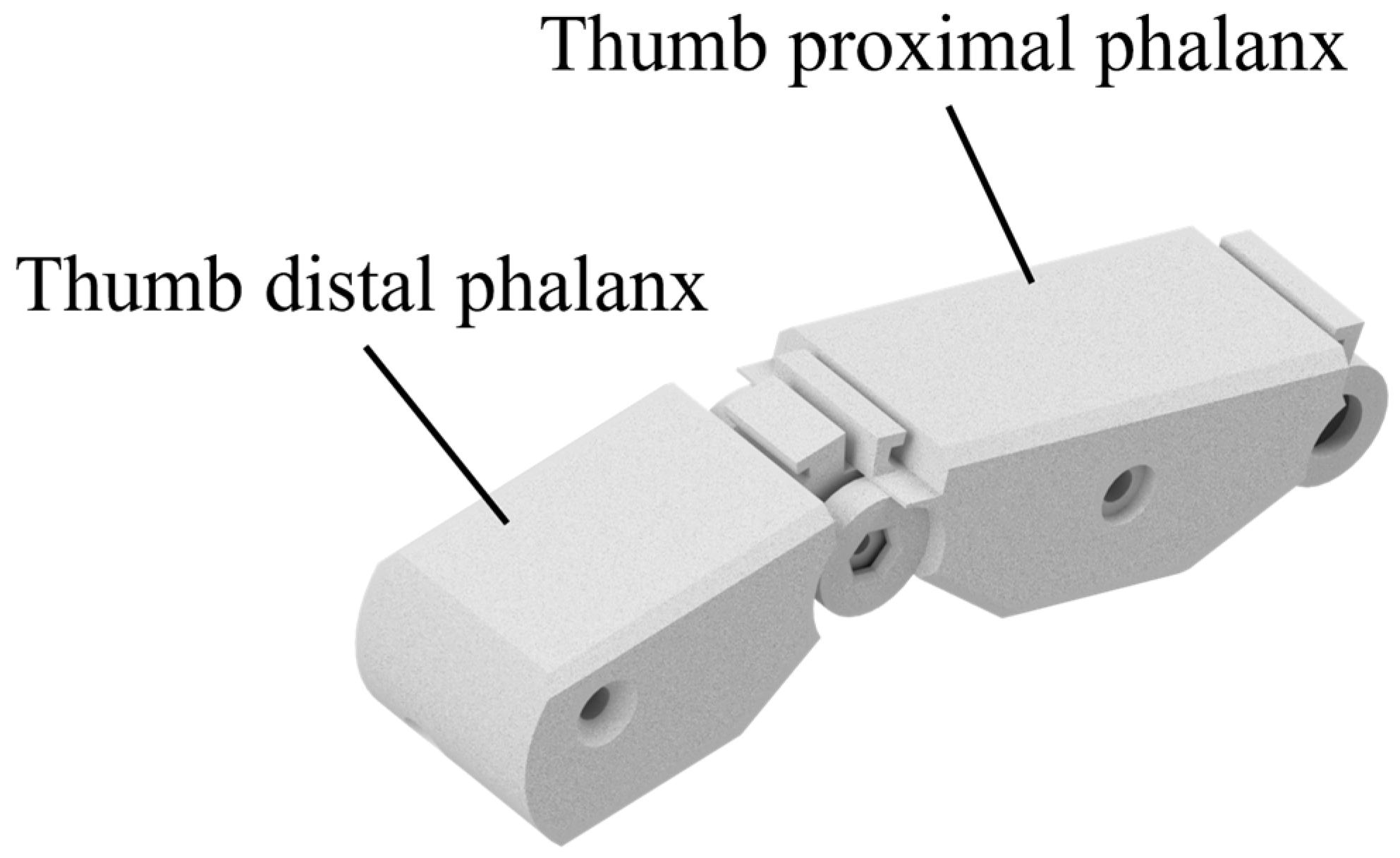
The thumb subassembly in Figure 2 is composed of four 3D-printed, two distal, and two proximal shell-like parts that assemble through two means: (1) snap fit and (2) screw-insert. The joints of the thumb are equipped with a ball bearing and a torsion spring.
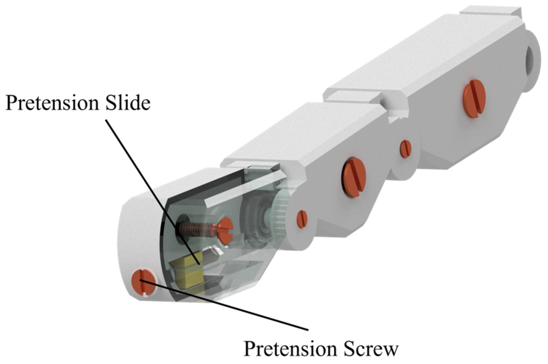
The finger subassembly presented in Figure 3 is like the thumb subassembly but has 3 phalanxes for a more anthropomorphic look. The 4 fingers have the same design with a pretension system in the fingertip and a channel for the actuation cable.

2.1.3. Palm Design

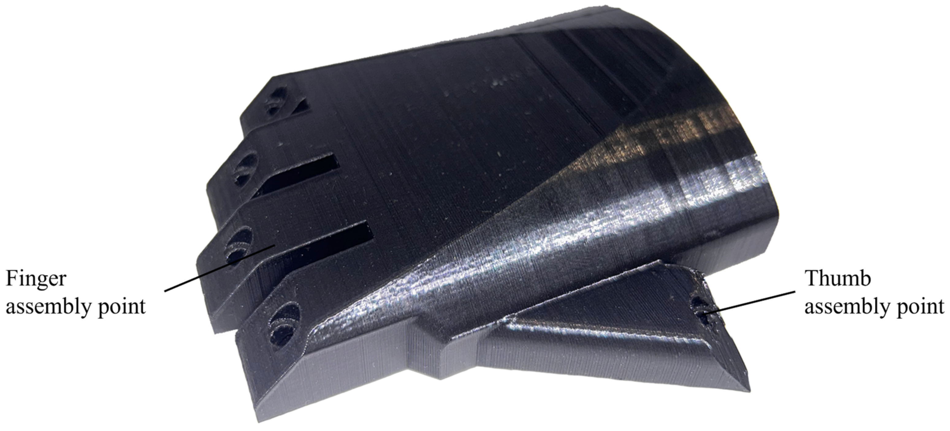
The hand subassembly in Figure 4 presents the assembly of all 5 fingers. It is made up of the palm structure subassembly, the palm cover on the dorsal side, and the fingers. The palm structure has also a built-in engagement part of the key to the locking system.
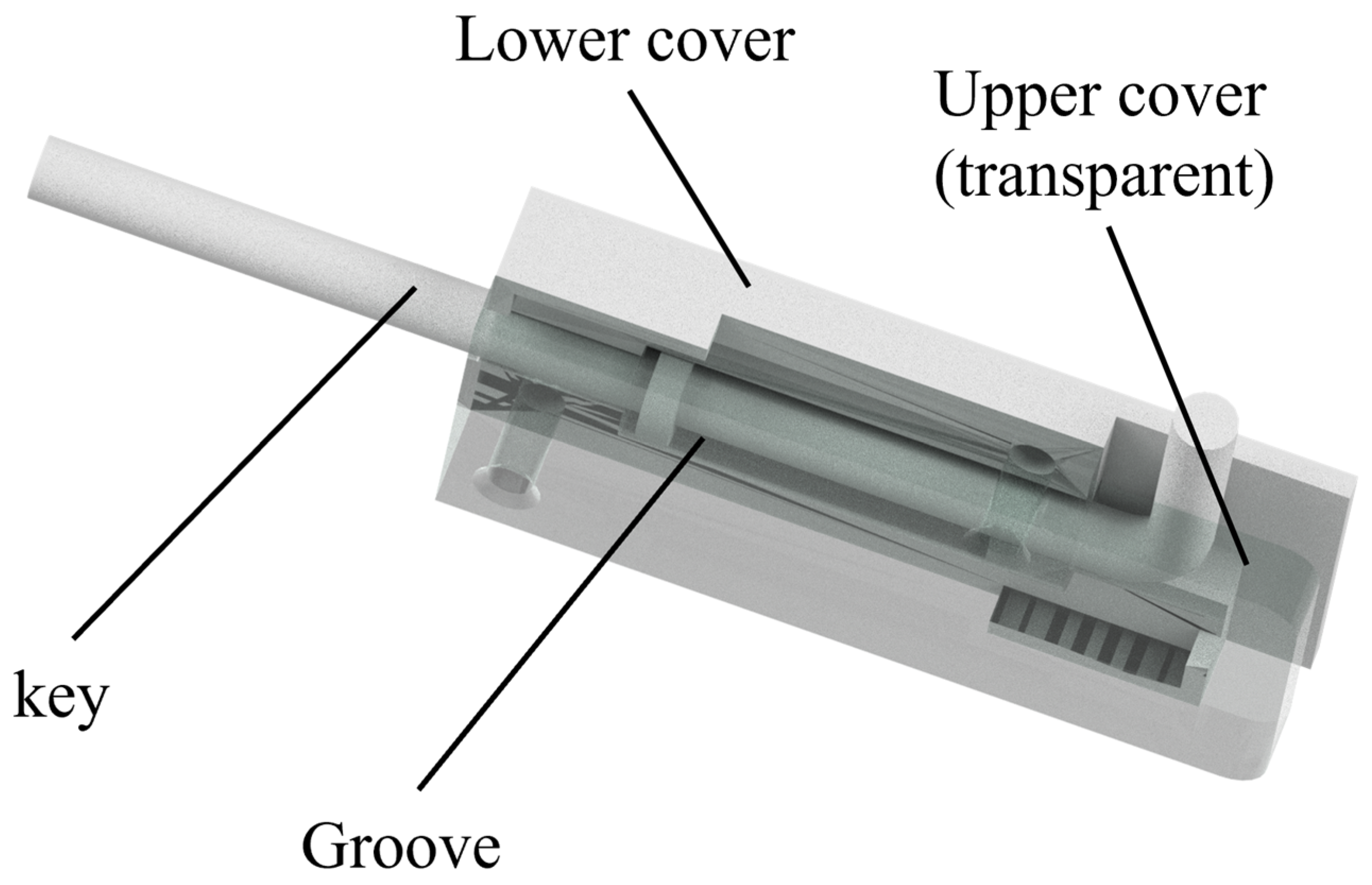
The locking system in Figure 5 is composed of 2 covers: (1) lower cover and (2) upper cover with a groove that allows for a key to travel freely. The key and spring mechanism of the locking system allows for the hand to be locked in a closed position.
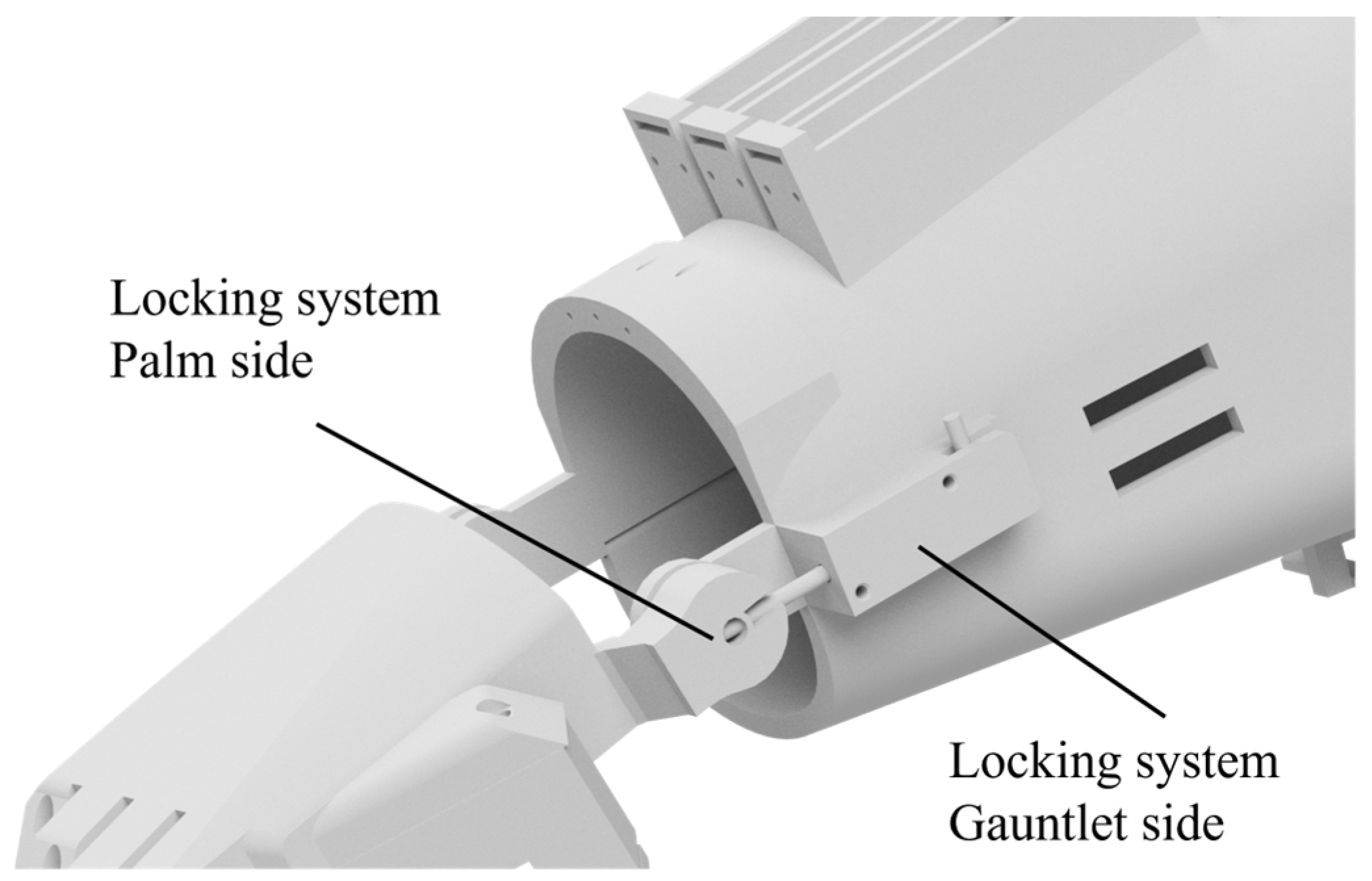
The positioning of the locking system as seen in Figure 6 is part on the palm structure and part on the gauntlet. The locking system is fixed with screws in threaded inserts on the gauntlet. When the user closes the hand, it has the chance to actuate the key and lock the position. This assumes the user has a healthy other hand.
The palm subassembly presented in Figure 1 is equipped with fingers modeled as seen in Figure 3. It has a pretension system illustrated in Figure 7. The thumb subassembly can be seen in Figure 2. The closed position of the device, shown in Figure 4, can be maintained using the locking mechanism, shown in Figure 5 and Figure 6.
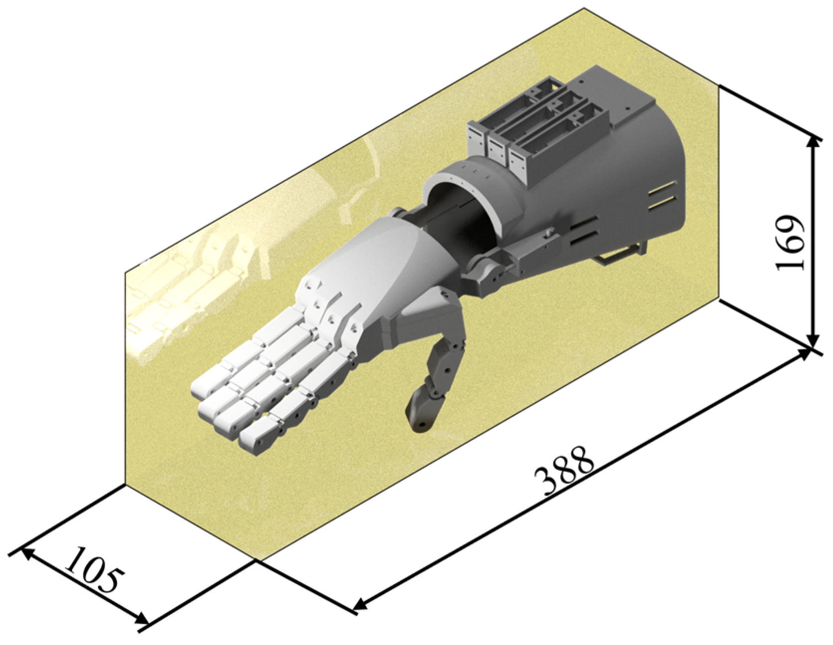
Although a human trial is considered, this might be a topic for future research. The gathered data are derived from 1 prototype that performed 1 set of the described experiments. Performance of the patients using the proposed design may be statistically studied in subsequent work. The overall design dimensions are illustrated in Figure 8. The unit length is millimeters as described by the engineering drawing standards.

2.1.4. Manufacturing of the Device

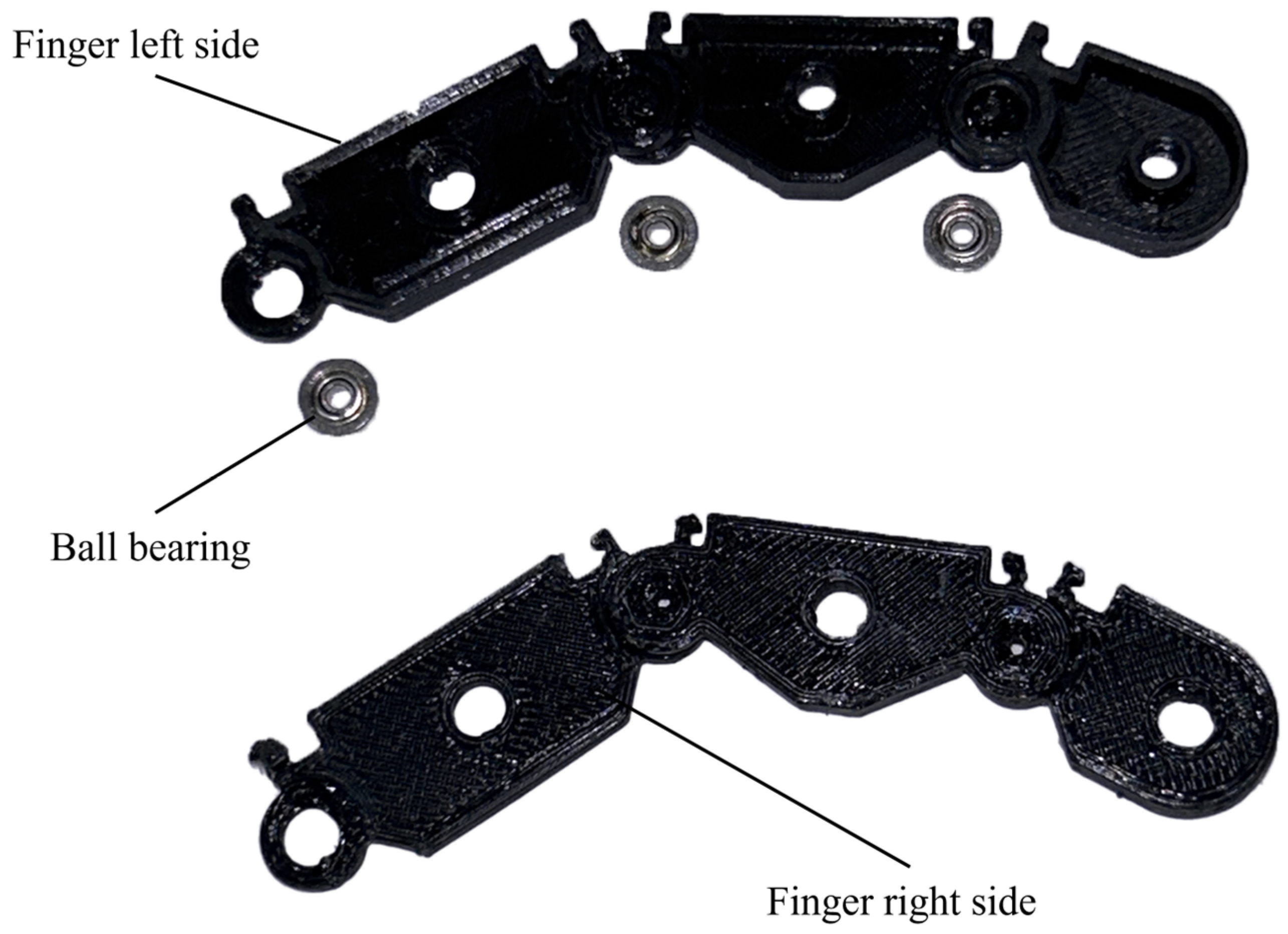
In Figure 9, the 3D-printed finger is shown. The subassembly contains 6 individual parts manufactured using PLA filament (Norditech Machinery S.R.l., Buteasa, Romania, EU) at a working temperature of t n = 210 ° for the nozzle and t b p = 60 ° for the build plate. The individual parts have an average manufacturing time of half an hour each. The nozzle used is Ø = 0.4   m m in diameter with the printing speed set at v = 50   m m / s .
Although AM technology has a growing material variety, not all of them meet the criteria for use in open-source upper limb prosthetics. The material selection was carried out using a decision matrix. The contents of the matrix can be found in the Supplementary Materials.
The proposed design was manufactured using a desktop 3D printer Creality Ender 3 (Creality 3D Technology Co., Ltd., Shenzhen, China). After the analysis with the multicriterial decision matrix, PLA was chosen as the manufacturing material for the proposed design.
To analyze the manufacturing potential of the prosthetic device, a list of the following materials was considered. The material characteristics were extracted from the datasheet of PLA [9], ASA [10], PETG [11], PETG + FC [12], PETG tungsten [13], PC + FC [14], PVB [15], F3 PA pure [16], F3 PA FC pro 15% FC [17], F3 PA FS pro 15% FS [18], F3 PA FS 30 pro 30% FS [19], PA11 FC [20], FilaFlexible 40 [21], TPU [22], Fiberflex 40D [23], Flexfill 98A [24], XT-CF 20 [25], ABS Carbon [26], ABS Kevlar [27], FKUR wood [28], PVA+ [29], Bronzefill [30], Copperfill [31], Corkfill [32], Steelfill [33], BVOH [34], CPE HG 100 [35], PP FS 30% [36], PEEK [37], and HIPS [38].
The decision matrix was compiled to decide the best material for manufacturing the device. To build the matrix, data were gathered and 2 tables were created. Firstly, the list of materials of which 3D printing filaments are made of was compiled in Table S1. Secondly, properties of the materials were extracted from their datasheets, as seen in Table S1. Thirdly, weights were attached to each of the properties. Lastly, based on the highest score in the decision matrix, the material was chosen.
The scores attained by each material were compared. A value of 1 to 7 is given to each material property in Table S2. The allocated score reflects the considered level of compatibility between the considered material property and the conditions set to reach the goal of manufacturing the parts of the proposed assembly design. Each property is weighted from 1 to 7, as seen in Table S2. The sum of the weights is 28. To compute the score of each material, the value is multiplied by the weight, and the sum total is given in the last column of Table S2.
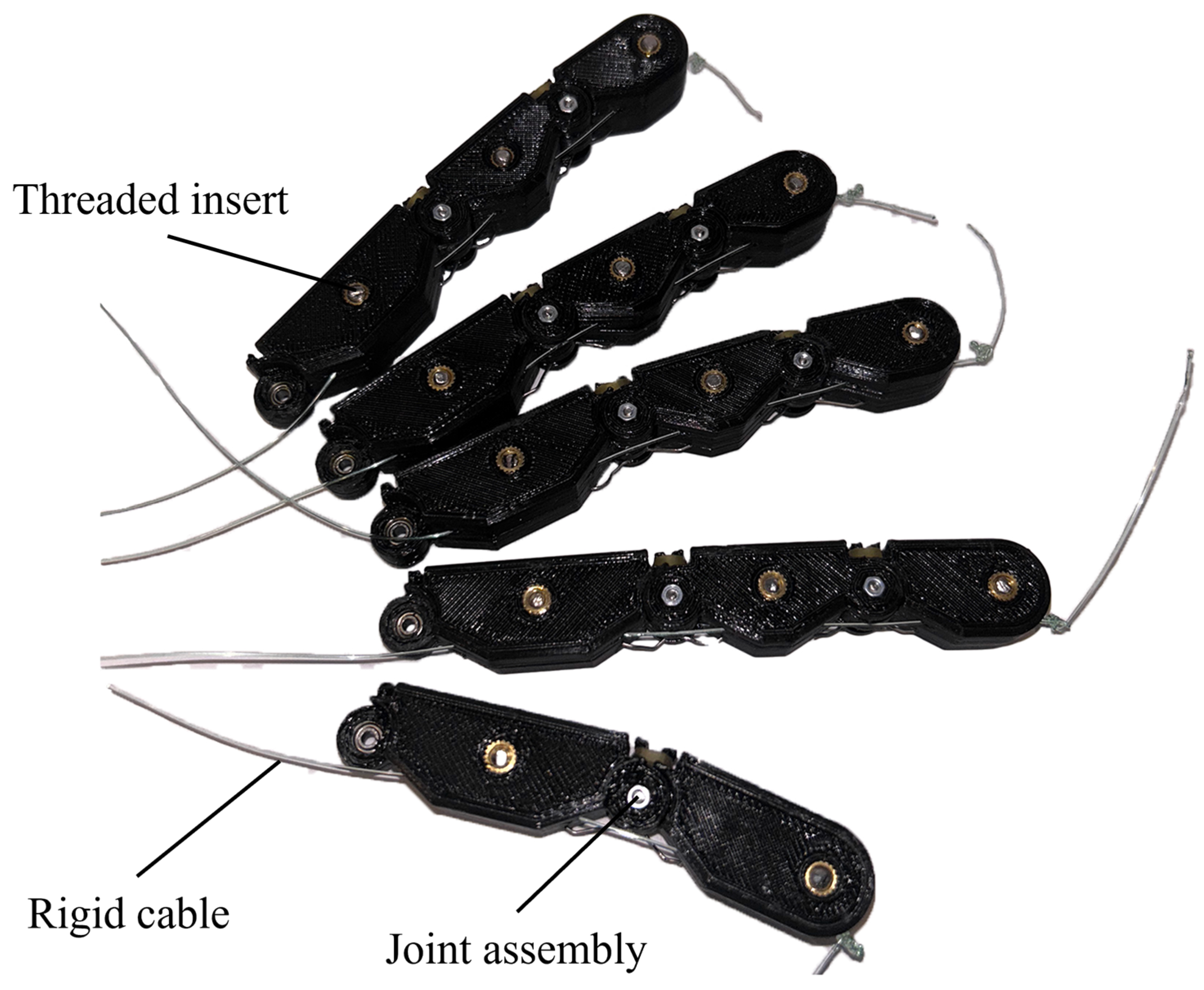
The finger subassembly is made up of multiple other parts besides the 3D-printed ones. The 2 adjacent parts of each phalanx assemble through a snap-fit method. At the ends of each phalanx a housing holds a miniature MR72zz deep groove ball bearing with a Ø o u t = 7   m m outside diameter, Ø i n = 3   m m inside diameter, and 3 mm width. The joint housing also holds a generic torsion spring responsible for keeping the fingers open. As illustrated in Figure 10, the phalanx has fasteners to prevent disassembly. There are 2 fastener systems: (1) a bolt–nut–washer arrangement and (2) a bolt–threaded insert assembly type. The rigid cable is a cable with limited elasticity present in Figure 10. This is so that it deforms minimally during the actuation. Usually, transitional prosthetics use 1 type of cable for actuation and another for the return function. The former should keep its dimensions during operation while the latter should constantly deform to accommodate the actuation and fulfil its role.
Traditionally, low-cost hand prosthetics use a rigid cable for actuation. A key feature of these devices is the high availability of materials in the parts list. In compliance with this practice, the use of fishing line cable was considered. The brand of rigid cable used is Konger X8 Braider (Konger Machinery Co, Ningbo, China), which is a multifilament based on high-density microfiber polyethylene.
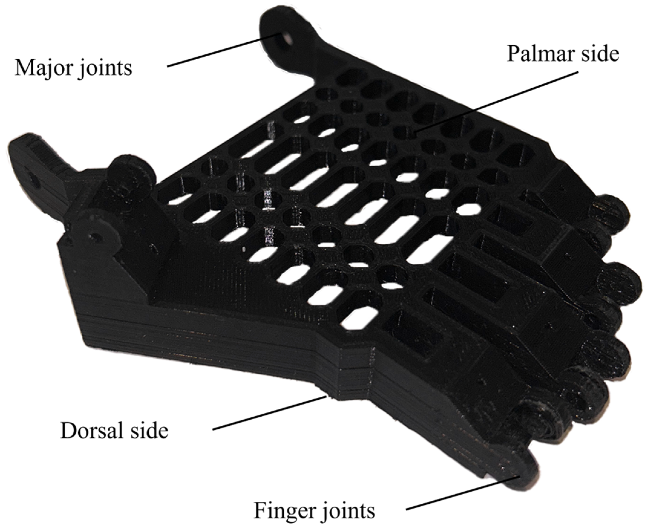
In Figure 11, the palm structure is illustrated. It has special assembly zones for the fingers. A group of 4 assembly links are located frontal–lateral and 1 other is placed radially on the side. The structural role played by the palm led to the design decision of placing a square pattern of holes on the palmar side responsible for ventilation and reinforcement of the device itself.
The palm cover in Figure 12 houses a maze of channels that allows for the finger actuation in either mode, mechanical or electrical. It is located on the dorsal side of the palm, and it is assembled with M3 threaded screws in threaded inserts near the finger articulations and with M2 self-tapping screws laterally on the side of the palm.
The actuation cable travels from the fingertips, through the palm channels up the gauntlet, and is tied to the motor shafts.
The thumb has 2 phalanxes and 2 joints and is located laterally. The other 4 fingers have 3 phalanxes and 3 joints and are placed at different elevation levels to simulate the human hand’s anatomy. The palm subassembly in Figure 13 also has a major joint that allows for assembly with the gauntlet. These joints house a ball bearing and have a side channel where a part of the locking system is situated. The thumb channel is the most complex. It makes the cable turn at a c a = 270 ° angle to travel from the palm to the gauntlet area.
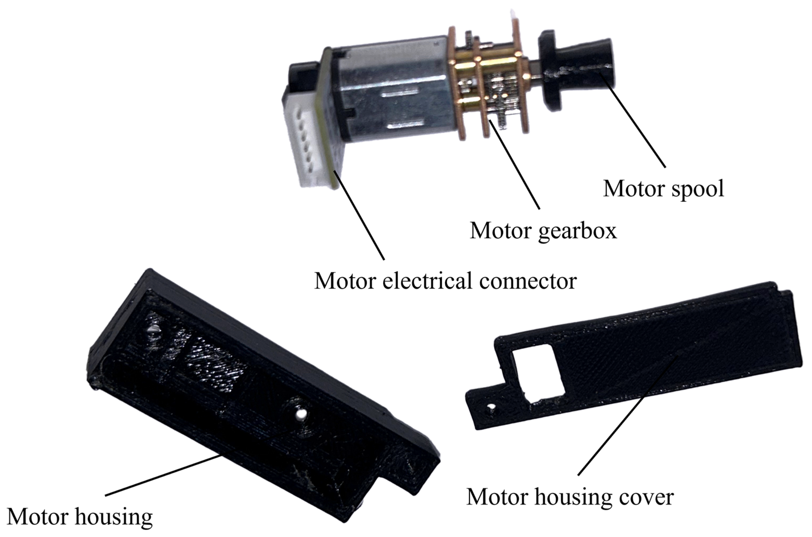
The motor subassembly in Figure 14 has a housing and a cover that allows for it to be secured on the gauntlet. A spool is present on the output shaft of the motor’s gearbox that allows for the cable to be spooled when trying to actuate the device.
The locking system has a component on the major joint of the palm structure and another one on the gauntlet, as seen in Figure 15. The system is made up of 2 covers with a channel between them which houses a locking key with a spring. The assembly allows for the device to lock in the closed position.
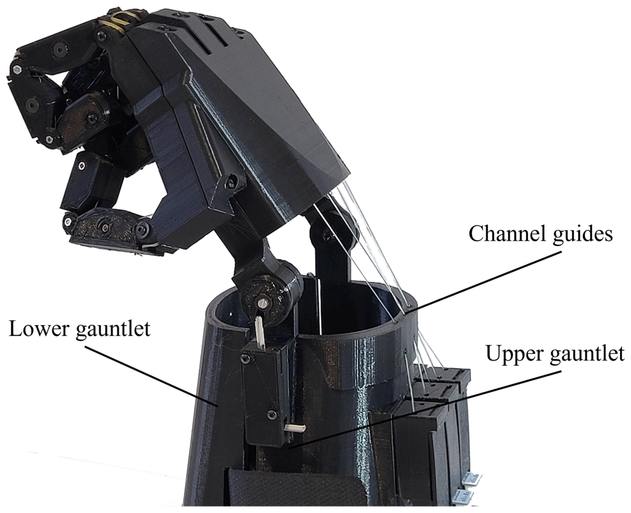
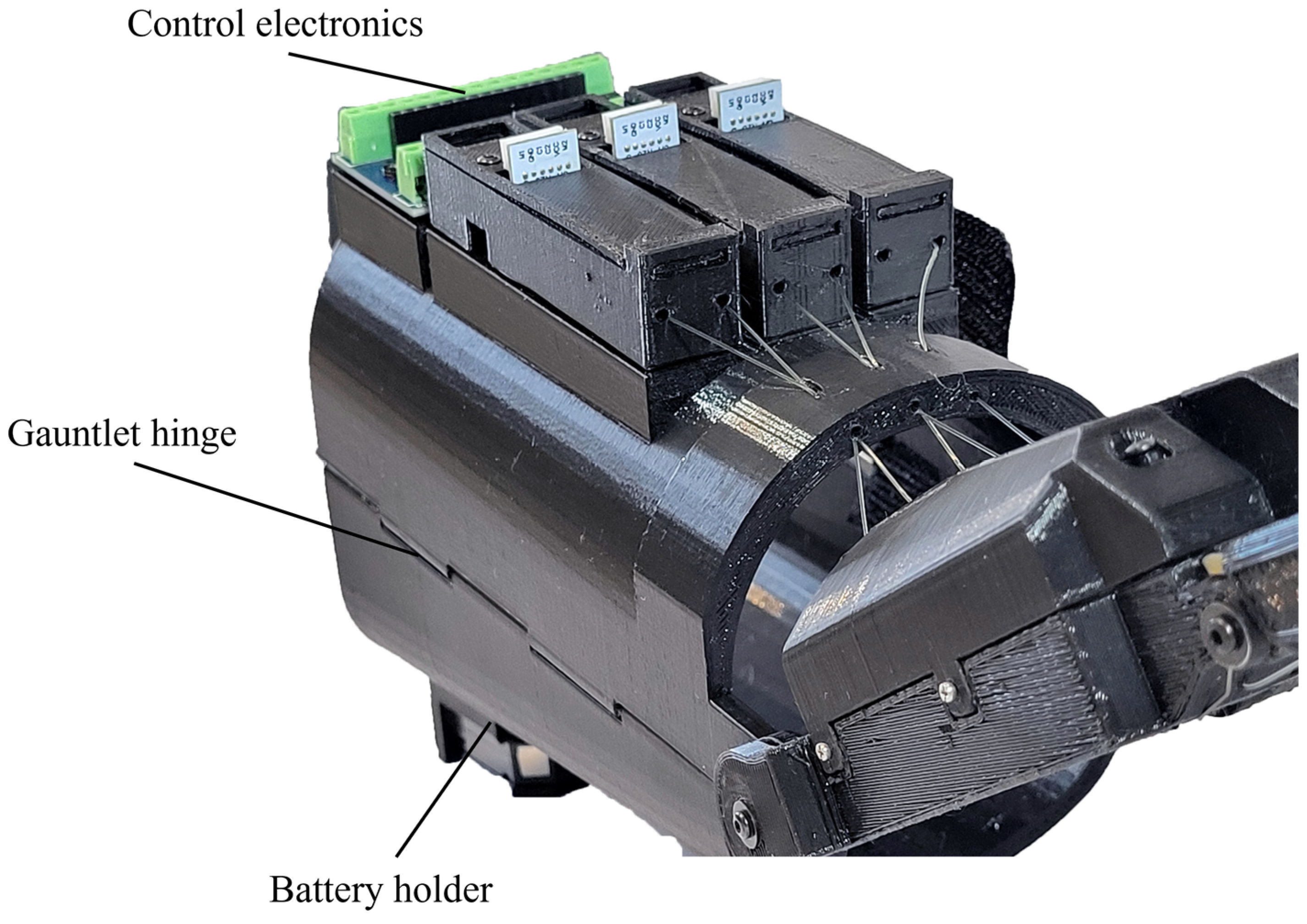
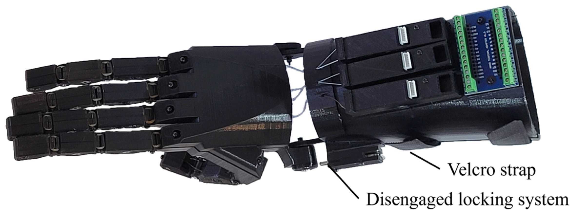
The gauntlet in Figure 16 is composed of 2 main parts: (1) the upper gauntlet, which has the motors and electronics mounted on it while also connecting to the palm, and (2) the lower gauntlet, which houses the battery. The 2 main parts are joined together by a metal pin that is inserted on the side in a hinge-like system on one side and a Velcro strap on the other side.
The full assembly of the device in Figure 17 has its finger distal made up of 2 parts that are assembled with a screw and threaded insert, and the method is similar throughout all the finger subassemblies. Two adjacent segments are assembled using a bolt and a nut that also supports the ball bearing and torsion spring. The finger subassembly has a channel through all the segments. A rigid cable travels through it and is used for actuation. In the distal part, the pretension system is located, which has a moving element that can either advance or return and with the help of a screw and a threaded insert can allow for fine cable tensioning adjustments.
During assembly of generic designs for transitional prosthetics, a tendency to lose parts due to unfixed joints was noticed. As a solution to the problem, metal fasteners were proposed. Furthermore, a similar problem occurred with rotational joint jamming or snapping, to which the roller bearing solution was given. Lastly, to achieve better performance for the return function of the device, instead of using a flexible cable, a torsion spring was added.

2.1.5. Grasping Testing

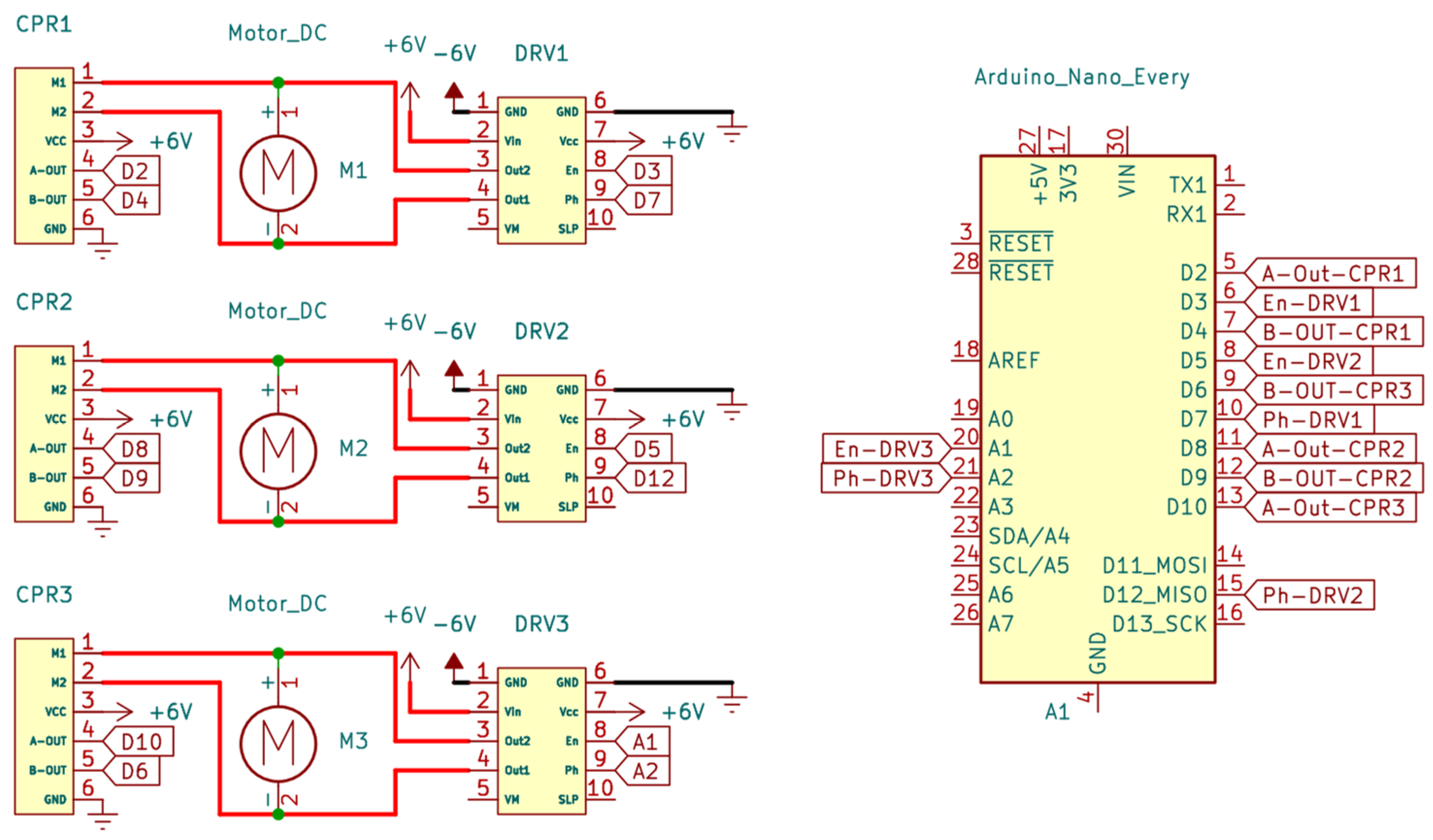
The miniature motors used to actuate the prototype have characteristics presented in Table 1. The device is equipped with 3 such motors. They are actuated by an Arduino board (Arduino, Somerville, MA, USA) connected through drivers.
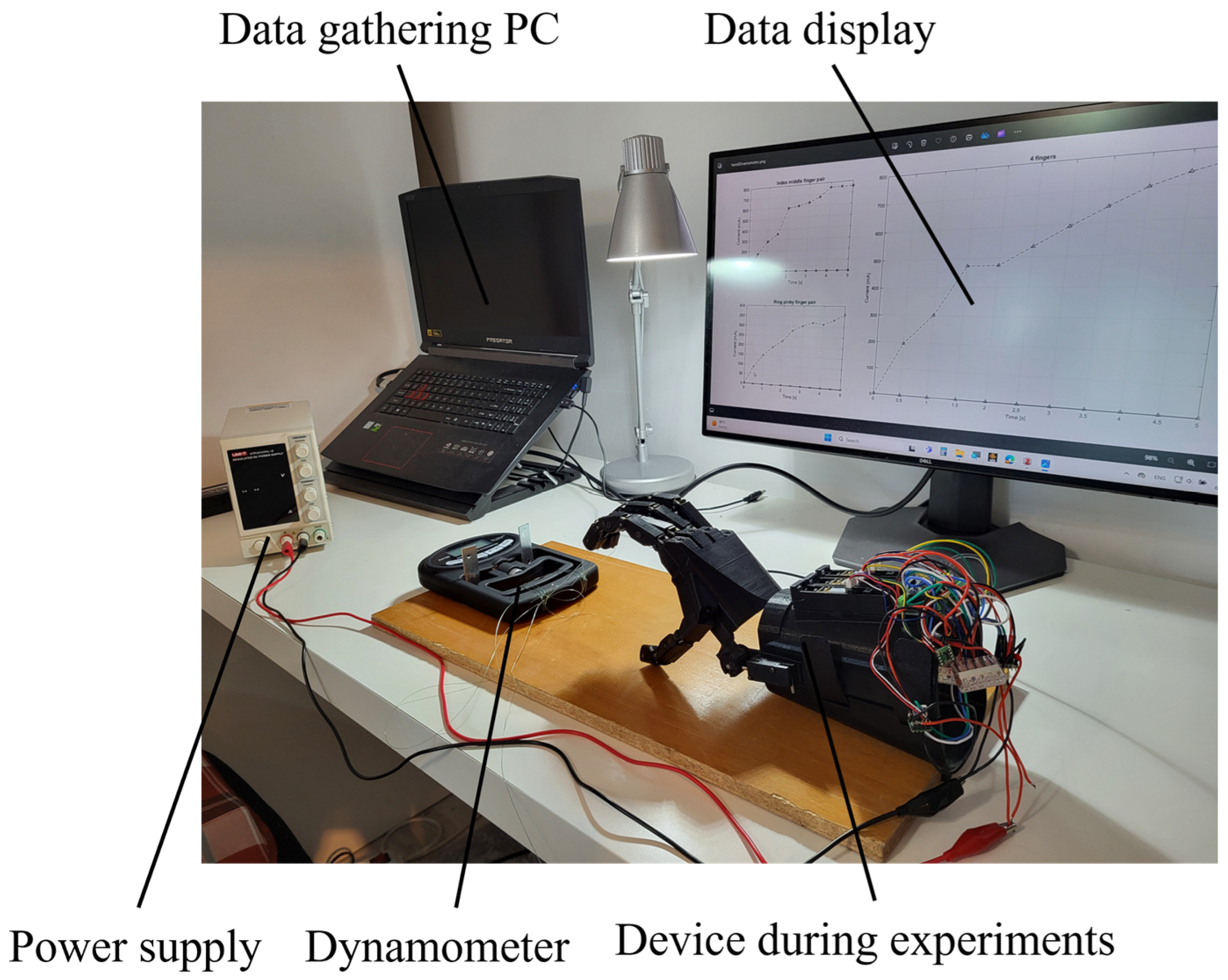
Tests were conducted with an electronic hand grip dynamometer Hichor EH 108 (Hichor, Shanghai, China). In this way, the prosthetic hand prototype grip strength was measured. The setup included a prosthetic device prototype constructed of mostly standardized parts. The custom parts were manufactured on a cartesian 3D printer using PLA filament.
The proposed prosthetic device consists of a hand and gauntlet. It is equipped with mechanical systems that can provide grasping functions to a partial hand amputee. The onboard electrical system ensures a level of capability for people with a weak stump. For our testing, we used a power supply to regulate voltage and supervise current drawn. The device is characterized by several subsystems, as seen in Figure 18.
In our testing, the device was linked to the digital hand grip dynamometer, and several trials were conducted to ensure the same results. The recorded current drawn along with the force were measured with respect to time. The experimental setup is illustrated in Figure 19.
In Figure 20, the overall schematic diagram is presented. On the left side, the CPR-type encoders measure the position of the motors and provide a signal to the Arduino board on the right side. The motors are routed through the DRV8838 drivers that are also connected to the controller board. The experiment was conducted by connecting the controller board to a computer.
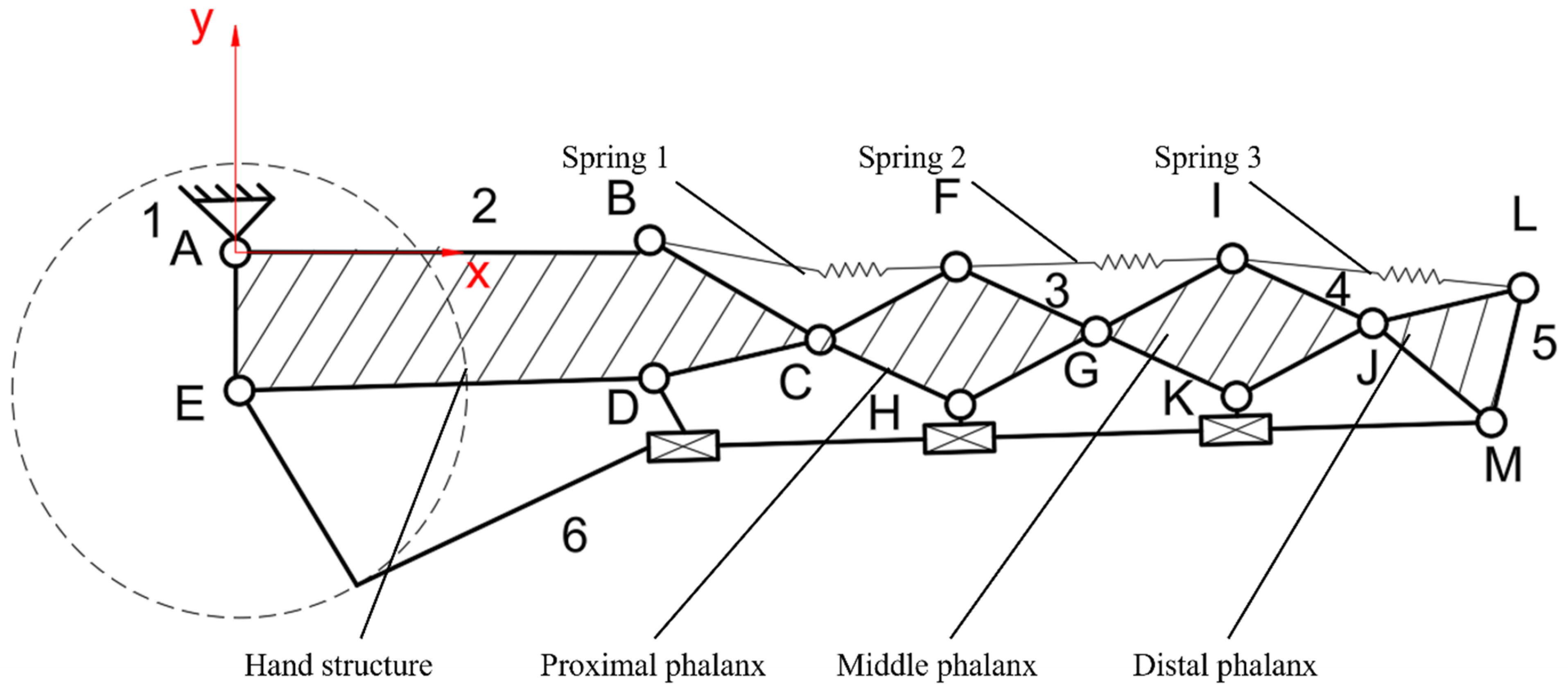
The kinematic diagram in Figure 21 indicates the types of kinematic joints used in the proposed design. In this case, C, G, and J are revolute joints, while D, H, and K are sliding joints. The rest of the letters indicate pin joints used for rigid cable and spring attachment. The studied position does not consider any collisions with an object. Point 1 is the hinge connection to the gauntlet and 2 is the plate representing the hand structure. The plates from 3 to 5 represent the proximal, middle, and distal phalanx, respectively. Point 6 is the rigid cable.

3. Results

3.1. Manufacturing Cost Analysis

The total cost described in Equation (1) as T c is defined as the relationship between the following: (1) the material part cost is considered as the material cost m c and part weight p w ; (2) p t is the printing time; (3) the usage cost is determined by the cost of the printer c p , upgrades cost u , maintenance costs m , average lifetime a l , rated power r p , and energy price e p ; and finally, (4) the part design cost is defined by the design time d t and design hourly rate d c .
T c = m c p w + p t c p + u + m a l + r p e p + d t d c
The full list of electronic parts used, and a subtotal cost can be found in Table 2. Alongside the motors, the drivers and batteries were considered. Also, the soldering supplies were considered for a comprehensive price capture.
Some mechanical components from Table 3 were considered. In the subtotal, everything was considered, from the ball bearings used to the different types of fasteners required for the assembly of the parts.
In Table 4, a list is presented of the different parts that were 3D-printed and their associated cost based on Equation (1). The cost of a single unit and the cost of the required number of parts are provided.
In the process of assembly other miscellaneous parts were procured. The number of parts as well as the price and total cost can be seen in Table 5.
In Table 6, the sum of all the subtotals gives the total cost of the prototype. The cost can be rounded to 1300 RON, which is the equivalent to 260 euros, making it suitable to be called a low-cost device.
With the amounts of material considered, the weight and build times are presented for each 3D-printed part. In Table 7, the cost of each part is illustrated, computed based on Equation (1).

3.2. Grasping Experimental Results

The measurement results are presented for the grasping motion during which the values of the current were measured.
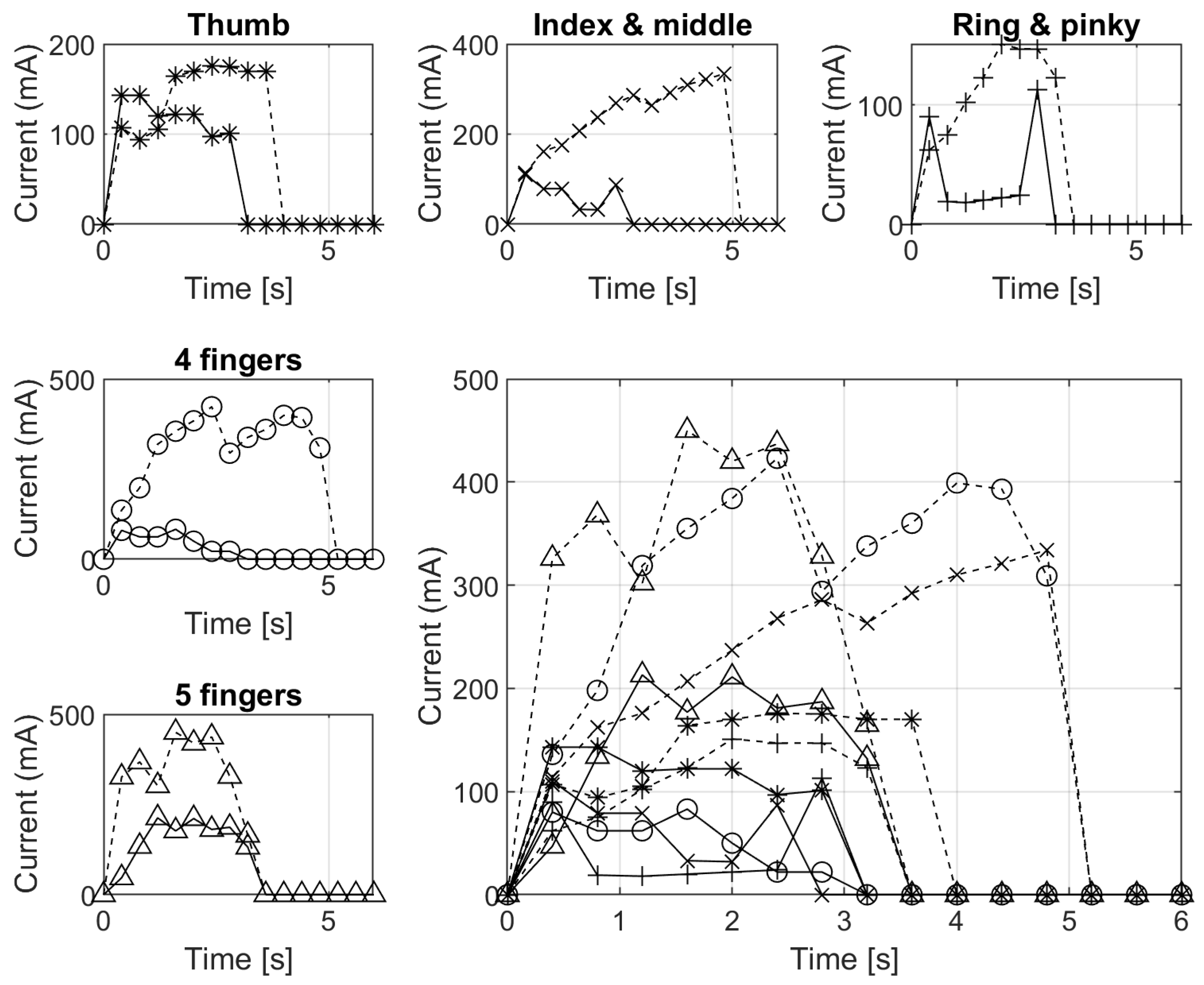
In Figure 22, the panels in the top row describe the current draw when actuating the thumb, index and middle finger, and ring and pinky finger, respectively. In the first column, the second and third panel display the drawn current from actuating the four fingers and five fingers. In the bottom right panel, a comparison can be seen between the five actuation modes. The solid lines represent the flexion movement while the dashed lines are for extension.
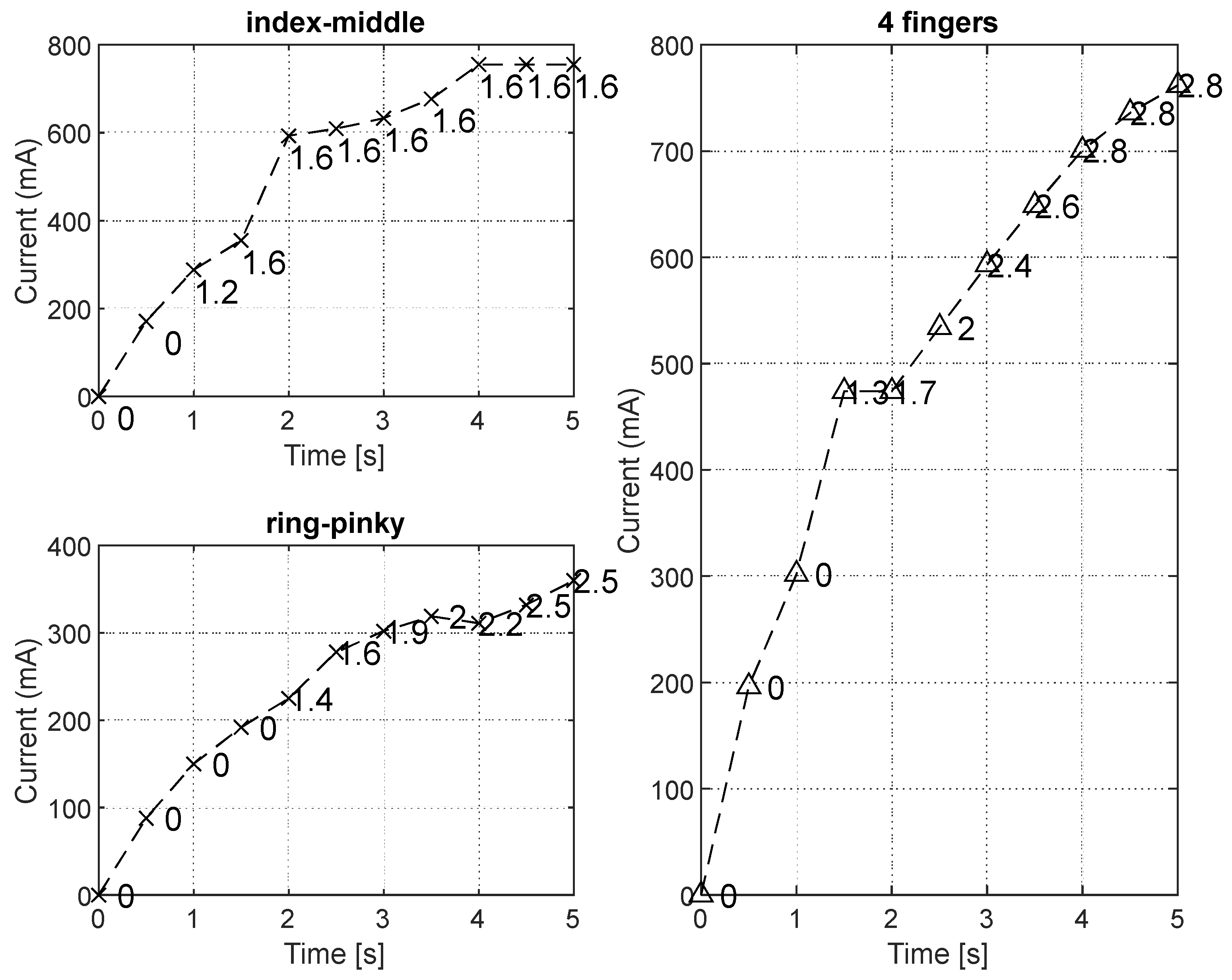
In Figure 23, the grasping force is measured. In the top left panel, the grasping force of the index and middle finger group is quantified over a 5 s time window. In the bottom-left corner, the panel illustrates the grasping force of the ring and pinky finger. Finally, in the right-side panel the four-finger actuation force is determined, reaching a peak of 2.8 kgf.

4. Discussion

The proposed device design is based on a line tendon actuation style. This method of actuation was chosen due to the small size and light weight of the tendon. It is different than linkage-based devices, which, although more precise, occupy more space [39].
Despite the device being designed like a body-powered partial hand prosthetic [40], it also has motorized actuation like an externally powered prosthetic [41]. This makes it a hybrid actuated prosthetic with low complexity of control so as to lead to ease of use and reduce prosthetic abandonment, which are historically interlinked [42]. The design describes a device for patients that (a) still have a functional wrist but (b) do not have remaining fingers [43].
The partial hand prosthetic device proposed design tends to lean towards an anthropomorphic style, but this is limited due to the overall goal of being as functional as possible. In this case, the device cannot be simultaneously anthropomorphic and functional without some compromise from a human-like device, like the one in [44].
Even if robotic arms are more advanced than other types of robotic hands, they benefit from a lot of available space as compared to only hands. Furthermore, in the case of partial hand prosthetics, the actuators have even less space because the proposed device houses the residual limb of the patient in the space where arms house their control systems [45].
The functionality of robotic hands grows with the implementation of thumb abduction/adduction and flexion/extension [46]. That said, the complexity of the device grows with this implementation but will be considered in further development of the proposed device.
Some improvements to the device may be carried out considering the innovations achieved in the sports prosthetics field. The energy storage and release mechanisms, which use various types of springs, can enhance performance of prosthetics using multi-material 3D printing [47]. Although this approach is promising, the complexity of the device is increased with the addition of the mechanism. Furthermore, the energy return components send the design towards a more mechanomorphic rather than anthropomorphic design.
Further development of manufacturing technology for fabrication of tactile sensors may lead to an advanced skin-like textile fabric enabling detection of pressure and temperature for patients that use a prosthetic device equipped with finger sensors [48] and embedded customized 3D-printed sEMG sensors [49]. Moreover, the evolution of conductive ABS- and PLA-based carbon composite parts with electrical conductivity may also contribute to better performance parts for upper limb prosthetics [50].
Previous research has shown that designing sockets for robotic arms and legs can make the difference between acceptance and rejection of prosthetic devices. Consequently, special attention needs to be paid to this subject. The material properties play a crucial role in the design of sockets. Most problems occur with delamination at the layer level and perspiration due to closed designs. To combat this, a bio-based material can be used in the design of such devices [51].
Some efforts have been made related to extended reality for development of prosthetics design with a pioneering methodology and a gamification layer. Despite the high complexity of the system, outcomes are promising [52].
This work is a preliminary study of the design and prototyping of a novel 3D-printed transitional partial hand prosthetic. A comparison between the proposed prototype and other existing models is presented in Table 8.
Limitations of this study include the absence of clinical trials with subjects to test the fit and function of the device in a real-world experiment. Furthermore, a kinematic analysis to improve function like in [53] may also improve the overall design.
The proposed prototype was designed from start to finish in CAD. The alternative to this might have been using a scanned model of the human hand. Consequently, the anthropomorphic degree of the device can be improved. Similarly, design work that started with a 3D scan ended up altering the shape of the hand to implement the much-needed mechanisms for assuring the functionality of the prosthetic [54].
Validation of the proposed design for use with patients may be considered. However, in the case of such devices, the study should include randomized clinical trials, which is a topic for future research implying a multidisciplinary team and a wide body of research. In the current paper, we proposed a variant that can be a basis for future research after not having found such devices in the literature.

5. Conclusions

Given the present research and cited work, it can be said that low-cost prosthetics still have many stages of advancement ahead. If sufficient time and resources are allocated, the results can be comparable to the success of open-source software, which closely competes with closed-source and commercial variants. The growing interest in prosthetics along with developments in low-cost AM and CAD software evolution will pave the way for the future.
Ongoing work is devoted to adding further features to the proposed device. In this paper, the best motion system for the project was established by using motors to generate the grasping force in a transitional partial hand prosthetic.
The main results, contributions, and novelty may be considered:
  • The proposed design differentiates itself from some of the rest by containing only standardized and 3D-printed parts. Furthermore, while other devices are either body-powered or externally powered, this prototype has both systems. Hybrid actuation is not something commonly found in low-cost transitional partial hand prosthetic devices. From the literature review, we found some hybrid shoulder devices, but those segment the device into two parts: (1) body-powered and (2) externally powered. The novelty in the proposed configuration is that the same segment is actuated in a hybrid manor.
  • From a cost point of view, even if some devices may be more inexpensive than the proposed device, it can be still considered as a low-cost device compared with some commercial offerings. The cost analysis resulted in a total of 260 euros for the cost of the prototype. On one hand, the proposed device has more features than its cheaper competition. On the other hand, the costs are much lower than the ones on the market.
  • The ball bearing rotational system and the torsional spring-based return system offer a more reliable control of motion. These systems may benefit the user even if the weight, complexity, and costs are higher than some other devices.
  • The resulted measured force of 2.8 kgf can be improved, as it is smaller than that of other commercial prosthetics. The used DC motors can provide this flexibility. Enhanced performance can be achieved using a similar set of motors that have better characteristics with a similar form factor. The issues that may occur by using such motors are related to availability and costs. When considering open-source upper limb prosthetic devices, a fully described design should be presented. The specifications must include a list of parts or bill of materials and the corresponding prices for the respective components. The current design has a price breakdown that is illustrated in Table 2, Table 3, Table 4 and Table 5 culminating with the total cost illustrated in Table 6 and resulted to be 260 euro. However, a performance increase can be attained if choosing more powerful motors. The 12 V HPCB Micro metal Gearmotor (Pololu Corporation, Las Vegas, NV, USA) may improve grip, while the total motor price rises by 20.9% from 435 RON to 550 RON. Since the new motors have a higher voltage rating, the battery system will also need to be updated to accommodate the new system. The effects of the considered change may be subject for future work.
  • Finally, the advantages of the device underlined using the hybrid actuation system, locking system, and rotational system may have a more significant impact than points where further work may be required, like lightweighting, increased speed, and developed force.
  • The limitations of this study include a small number of experiments conducted to fully evaluate the behavior of the prototype. Furthermore, no human trials were carried out to validate the readiness of the device for actual use. In future work, a higher number of experiments are considered, such as more actuation variety to optimize the existing prototype and gradually move on from the experimental phase towards a fully functioning application.

Supplementary Materials

The following supporting information can be downloaded at: https://www.mdpi.com/article/10.3390/app14198929/s1, Table S1. Establishing the criteria and extracting the material properties. Table S2. Point allocation and decision.

Author Contributions

Conceptualization, F.-F.R.; methodology, F.-F.R.; formal analysis, F.-F.R.; investigation, F.-F.R.; resources, F.-F.R.; writing—original draft preparation, F.-F.R.; visualization, F.-F.R.; supervision, I.S. All authors have read and agreed to the published version of the manuscript.

Funding

This research received no external funding.

Institutional Review Board Statement

Not applicable.

Informed Consent Statement

Not applicable.

Data Availability Statement

The original contributions presented in this study are included in the article/Supplementary Materials; further inquiries can be directed to the corresponding author.

Conflicts of Interest

The authors declare no conflicts of interest.

Abbreviations

The following abbreviations are used in this manuscript:
ADLsActivities of daily living
AMAdditive manufacturing
BPBody-powered
CADComputer-aided design
EPExternally powered
PLAPolylactic acid
sEMGSurface electromyography

References

  1. Enache, I.-C.; Cristina, I.-M.; Chivu, O.-R.; Mates, I.; Ionita, E.; Geambasu, G. The Influence of 3D Printing Parameters on the Mechanical Behavior of PLA. Mater. Plast. 2024, 61, 82–92. [Google Scholar] [CrossRef]
  2. Kate, J.T.; Smit, G.; Breedveld, P. 3D-printed upper limb prostheses: A review. Disabil. Rehabil. Assist. Technol. 2017, 12, 300–314. [Google Scholar] [CrossRef] [PubMed]
  3. Wendo, K.; Barbier, O.; Bollen, X.; Schubert, T.; Lejeune, T.; Raucent, B.; Olszewski, R. Open-Source 3D Printing in the Prosthetic Field—The Case of Upper Limb Prostheses: A Review. Machines 2022, 10, 413. [Google Scholar] [CrossRef]
  4. Satriawan, A.; Trusaji, W.; Irianto, D.; Anshori, I.; Setianingsih, C.; Nurtriandari, E.; Goesasi, R.Z. Karla: A Simple and Affordable 3-D Printed Body-Powered Prosthetic Hand with Versatile Gripping Technology. Designs 2023, 7, 37. [Google Scholar] [CrossRef]
  5. Esposito, D.; Savino, S.; Andreozzi, E.; Cosenza, C.; Niola, V.; Bifulco, P. The “Federica” Hand. Bioengineering 2021, 8, 128. [Google Scholar] [CrossRef]
  6. Zuniga, J.; Katsavelis, D.; Peck, J.; Stollberg, J.; Petrykowski, M.; Carson, A.; Fernandez, C. Cyborg beast: A low-cost 3d-printed prosthetic hand for children with upper-limb differences. BMC Res. Notes 2015, 8, 10. [Google Scholar] [CrossRef]
  7. Thingiverse.com. Flexy-Hand by Gyrobot. Available online: https://www.thingiverse.com/thing:242639 (accessed on 27 December 2022).
  8. Varaganti, P.; Seo, S. Recent Advances in Biomimetics for the Development of Bio-Inspired Prosthetic Limbs. Biomimetics 2024, 9, 273. [Google Scholar] [CrossRef]
  9. Prusa, J. Prusament PLA by Prusa Polymers; Technical Datasheet Rev. 1.1; Prusa Research: Prague, Czech Republic, 2022. [Google Scholar]
  10. Prusa, J. Prusament ASA by Prusa Polymers; Technical Datasheet Rev. 1.1; Prusa Research: Prague, Czech Republic, 2022. [Google Scholar]
  11. Prusa, J. Prusament PETG by Prusa Polymers; Technical Datasheet Rev. 1.1; Prusa Research: Prague, Czech Republic, 2022. [Google Scholar]
  12. Prusa, J. Prusament PETG Carbon Fiber Black by Prusa Polymers; Technical Datasheet Rev. 1.0; Prusa Research: Prague, Czech Republic, 2022. [Google Scholar]
  13. Prusa, J. Prusament PETG Tungsten 75% by Prusa Polymers; Technical Datasheet Rev. 1.0; Prusa Research: Prague, Czech Republic, 2023. [Google Scholar]
  14. Prusa, J. Prusament PC Blend Carbon Fiber by Prusa Polymers; Technical Datasheet Rev. 2.0-OY; Prusa Research: Prague, Czech Republic, 2023. [Google Scholar]
  15. Prusa, J. Prusament PVB by Prusa Polymers; Technical Datasheet Rev. 1.1; Prusa Research: Prague, Czech Republic, 2022. [Google Scholar]
  16. Philipp, K. F3 PA Pure Pro; Technical Datasheet; Fiberthree GmbH: Darmstadt, Germany, 2020. [Google Scholar]
  17. Philipp, K. F3 PA-CF Pro; Technical Datasheet; Fiberthree GmbH: Darmstadt, Germany, 2020. [Google Scholar]
  18. Philipp, K. F3 PA-GF Pro; Technical Datasheet; Fiberthree GmbH: Darmstadt, Germany, 2020. [Google Scholar]
  19. Philipp, K. F3 PA-GF30 Pro; Technical Datasheet; Fiberthree GmbH: Darmstadt, Germany, 2021. [Google Scholar]
  20. Prusa, J. Prusament PA11 Carbon Fiber by Prusa Polymers; Technical Datasheet Rev. 1.0; Prusa Research: Prague, Czech Republic, 2022. [Google Scholar]
  21. Asgharzadeh, M. FilaFlexible40 Filament; Technical Datasheet; Filatech 3D Printing Industries FZC, Technology Park: Al Hamra Island, United Arab Emirates, 2021. [Google Scholar]
  22. Rouleaux, R. ColorFabb varioShore TPU; Technical Datasheet Rev. 1.0; ColorFabb B.V.: Belfeld, The Netherlands, 2019; Available online: https://www.prusa3d.com/file/853929/tds-technical-data-sheet.pdf (accessed on 24 June 2023).
  23. Łukasik, Ł. Fiberlogy Fiberflex 40D; Technical Datasheet; Fiberlab S.A.: Brezie, Poland, 2022; Available online: https://fiberlogy.com/wp-content/uploads/2022/12/FIBERLOGY_FIBERFLEX_40D_TDS.pdf (accessed on 24 June 2023).
  24. Dolecek, J. Flexfill 98A; Technical Datasheet; Fillamentum Manufacturing: Hulin, Czech Republic. Available online: https://fillamentum.com/wp-content/uploads/2020/10/Technical-Data-Sheet_Flexfill-TPU-98A_26082019.pdf (accessed on 24 June 2023).
  25. Rouleaux, R. ColorFabb XT-CF20; Technical Datasheet Rev. 1.0; ColorFabb B.V.: Belfeld, The Netherlands, 2017; Available online: https://colorfabb.com/media/datasheets/tds/colorfabb/TDS_E_ColorFabb_XT_CF20.pdf (accessed on 24 June 2023).
  26. de Hubert, B. ABS CARBON KIMYA; Technical Datasheet; ARMOR SAS: Nantes, France. Available online: https://www.kimya.fr/wp-content/uploads/2018/09/kimya_fiche_ABS-CARBON-A4-EN.pdf (accessed on 24 June 2023).
  27. de Hubert, B. ABS KEVLAR KIMYA; Technical Datasheet; ARMOR SAS: Nantes, France. Available online: https://www.kimya.fr/wp-content/uploads/2018/09/kimya_fiche_ABS-KEVLAR-A4-EN.pdf (accessed on 24 June 2023).
  28. Zimmermann, P. Fibrolon® V 135002; Technical Datasheet Rev. 1.1; FKuR Kunststoff GmbH: Willich, Germany, 2014. [Google Scholar]
  29. Mårtensson, J. Select PVA+; Technical Datasheet; Prima Creator: Malmö, Sweede. Available online: https://cdn.shopify.com/s/files/1/2424/8853/files/Prima_PVA__webb.pdf?293 (accessed on 24 June 2023).
  30. Rouleaux, R. ColorFabb BronzeFill; Technical Datasheet Rev. 1.0; ColorFabb B.V.: Belfeld, The Netherlands, 2017; Available online: https://colorfabb.com/media/datasheets/tds/colorfabb/TDS_E_ColorFabb_BronzeFill.pdf (accessed on 24 June 2023).
  31. Rouleaux, R. ColorFabb CopperFill; Technical Datasheet Rev. 1.0; ColorFabb B.V.: Belfeld, The Netherlands, 2017; Available online: https://colorfabb.com/media/datasheets/tds/colorfabb/TDS_E_ColorFabb_CopperFill.pdf (accessed on 24 June 2023).
  32. Rouleaux, R. CorkFill; Technical Datasheet Rev. 1.0; ColorFabb: Belfeld, The Netherlands, 2020; Available online: https://colorfabb.com/media/datasheets/tds/colorfabb/TDS_E_ColorFabb_corkFill.pdf (accessed on 24 June 2023).
  33. Rouleaux, R. ColorFabb SteelFill; Technical Datasheet Rev. 1.0; ColorFabb B.V.: Belfeld, The Netherlands, 2017; Available online: https://colorfabb.com/media/datasheets/tds/colorfabb/TDS_E_ColorFabb_SteelFill.pdf (accessed on 24 June 2023).
  34. Alberts, C. 3D BVOH Filament’; Technical Datasheet; Verbatim: Charlotte, NC, USA. Available online: https://www.verbatim-europe.com/en/3d/products/verbatim-bvoh-filament-175-mm-natural-55903 (accessed on 24 June 2023).
  35. Dolecek, J. CPE HG100; Technical Datasheet; Fillamentum Manufacturing: Hulin, Czech Republic. Available online: https://fillamentum.com/wp-content/uploads/2020/10/Technical-Data-Sheet_CPE-HG100_03012019.pdf (accessed on 24 June 2023).
  36. Back, M. PPGF 30 by Innofil3D BV; Technical Datasheet Rev. 1.0; BASF 3D Printing Solutions GmbH: Heidelberg, Germany, 2018. [Google Scholar]
  37. Howlett, M. ThermaXTM PEEK 3D Printing Filament; Technical Datasheet Rev. 3.0; 3DXTECH Adaptive Manufacturing: Grand Rapids, MI, USA, 2020. [Google Scholar]
  38. Dolecek, J. HIPS Extrafill; Technical Datasheet; Fillamentum Manufacturing: Hulin, Czech Republic. Available online: https://fillamentum.com/wp-content/uploads/2020/10/Technical-Data-Sheet_HIPS-Extrafill_03012019.pdf (accessed on 24 June 2023).
  39. Wahit, M.A.A.; Ahmad, S.A.; Marhaban, M.H.; Wada, C.; Izhar, L.I. 3D Printed Robot Hand Structure Using Four-Bar Linkage Mechanism for Prosthetic Application. Sensors 2020, 20, 4174. [Google Scholar] [CrossRef]
  40. Zuniga, J.M. 3D Printed Antibacterial Prostheses. Appl. Sci. 2018, 8, 1651. [Google Scholar] [CrossRef]
  41. Slade, P.; Akhtar, A.; Nguyen, M.; Bretl, T. Tact: Design and performance of an open-source, affordable, myoelectric prosthetic hand. In Proceedings of the 2015 IEEE International Conference on Robotics and Automation (ICRA), Seattle, WA, USA, 26–30 May 2015; pp. 6451–6456. [Google Scholar] [CrossRef]
  42. Manero, A.; Smith, P.; Sparkman, J.; Dombrowski, M.; Courbin, D.; Kester, A.; Womack, I.; Chi, A. Implementation of 3D Printing Technology in the Field of Prosthetics: Past, Present, and Future. Int. J. Environ. Res. Public Health 2019, 16, 1641. [Google Scholar] [CrossRef]
  43. Ryu, W.; Choi, Y.; Choi, Y.J.; Lee, S. Development of a Lightweight Prosthetic Hand for Patients with Amputated Fingers. Appl. Sci. 2020, 10, 3536. [Google Scholar] [CrossRef]
  44. Dunai, L.; Novak, M.; Espert, C.G. Human Hand Anatomy-Based Prosthetic Hand. Sensors 2020, 21, 137. [Google Scholar] [CrossRef] [PubMed]
  45. Yurova, V.A.; Velikoborets, G.; Vladyko, A. Design and Implementation of an Anthropomorphic Robotic Arm Prosthesis. Technologies 2022, 10, 103. [Google Scholar] [CrossRef]
  46. Andrés-Esperanza, J.; Iserte-Vilar, J.L.; Llop-Harillo, I.; Pérez-González, A. Effect of the Thumb Orientation and Actuation on the Functionality and Performance of Affordable Prosthetic Hands: Obtaining Design Criteria. Biomimetics 2022, 7, 233. [Google Scholar] [CrossRef]
  47. Park, J.W.; Greenspan, B.; Tabb, T.; Gallo, E.; Danielescu, A. 3D Printed Energy Return Elements for Upper Limb Sports Prosthetics. Prosthesis 2023, 5, 13–34. [Google Scholar] [CrossRef]
  48. Fares, H.; Abbass, Y.; Valle, M.; Seminara, L. Validation of Screen-Printed Electronic Skin Based on Piezoelectric Polymer Sensors. Sensors 2020, 20, 1160. [Google Scholar] [CrossRef]
  49. Wolterink, G.; Dias, P.; Sanders, R.G.P.; Muijzer, F.; van Beijnum, B.-J.; Veltink, P.; Krijnen, G. Development of Soft sEMG Sensing Structures Using 3D-Printing Technologies. Sensors 2020, 20, 4292. [Google Scholar] [CrossRef]
  50. Pentek, A.; Nyitrai, M.; Schiffer, A.; Abraham, H.; Bene, M.; Molnar, E.; Told, R.; Maroti, P. The Effect of Printing Parameters on Electrical Conductivity and Mechanical Properties of PLA and ABS Based Carbon Composites in Additive Manufacturing of Upper Limb Prosthetics. Crystals 2020, 10, 398. [Google Scholar] [CrossRef]
  51. Plesec, V.; Humar, J.; Dobnik-Dubrovski, P.; Harih, G. Numerical Analysis of a Transtibial Prosthesis Socket Using 3D-Printed Bio-Based PLA. Materials 2023, 16, 1985. [Google Scholar] [CrossRef]
  52. Górski, F.; Łabudzki, R.; Żukowska, M.; Sanfilippo, F.; Ottestad, M.; Zelenay, M.; Băilă, D.-I.; Pacurar, R. Experimental Evaluation of Extended Reality Technologies in the Development of Individualized Three-Dimensionally Printed Upper Limb Prostheses. Appl. Sci. 2023, 13, 8035. [Google Scholar] [CrossRef]
  53. Berceanu, C.; Tarni, D. About the Kinematics and Control System of an Anthropomorphic Hand Usable as Prosthesis. U.P.B. Sci. Bull. 2011, 73, 23–30. [Google Scholar]
  54. Radu (Frenț), C.; Roșu, M.M.; Matei, L.; Ungureanu, L.M.; Iliescu, M. Concept, Design, Initial Tests and Prototype of Customized Upper Limb Prosthesis. Appl. Sci. 2021, 11, 3077. [Google Scholar] [CrossRef]
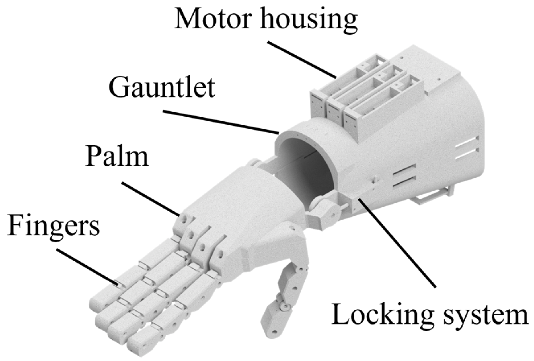
Figure 1. Assembly of the transitional prosthetic device.
Applsci 14 08929 g001
Figure 2. Thumb subassembly of the proposed prototype.
Applsci 14 08929 g002
Figure 3. Inside geometry of the finger subassembly.
Applsci 14 08929 g003
Figure 4. Palm subassembly with closed fingers a vent area and the major joint.
Applsci 14 08929 g004
Figure 5. Element of the locking system subassembly placed laterally on the device.
Applsci 14 08929 g005
Figure 6. Position of locking system assembled view.
Applsci 14 08929 g006
Figure 7. Pretension system subassembly with view of inside geometry.
Applsci 14 08929 g007
Figure 8. Overall dimensions of the prototype.
Applsci 14 08929 g008
Figure 9. Three-dimensionally printed finger subassembly and bearing placement.
Applsci 14 08929 g009
Figure 10. Assembled 3D-printed fingers with tendons attached.
Applsci 14 08929 g010
Figure 11. Three-dimensionally printed palm structure featuring the finger joints and major joint.
Applsci 14 08929 g011
Figure 12. Three-dimensionally printed palm cover with assembly points.
Applsci 14 08929 g012
Figure 13. Assembled 3D-printed palm with cover and fingers.
Applsci 14 08929 g013
Figure 14. Motor subassembly with housing and cover.
Applsci 14 08929 g014
Figure 15. Three-dimensionally printed locking system area with respect to the gauntlet.
Applsci 14 08929 g015
Figure 16. Three-dimensionally printed hinged gauntlet subassembly control electronic and battery holder.
Applsci 14 08929 g016
Figure 17. Fully assembled 3D-printed device with locking system in disengaged position.
Applsci 14 08929 g017
Figure 18. Prototype components and equipment setup by category.
Applsci 14 08929 g018
Figure 19. Grasping force experimental setup with prototype connected to power supply, measurement device, and computer.
Applsci 14 08929 g019
Figure 20. Schematic diagram of the prototype.
Applsci 14 08929 g020
Figure 21. Kinematic diagram of one finger attached to the palm of the device.
Applsci 14 08929 g021
Figure 22. Comparison of current drawn with respect to time for grasp actuation.
Applsci 14 08929 g022
Figure 23. Comparison of grasping force generated based on current drawn with respect to time during actuation.
Applsci 14 08929 g023
Table 1. DC motors mechanical and electrical characteristics.
PropertyValue
Rated voltage [V]6
Stall current [A]0.36
No-load current (mA)40
No-load speed (RPM)45
Extrapolated stall torque (kg ×cm)2
Max power [W]0.22
Gear ratio298:1
Motor windingLP
Brush typeMetal
Table 2. Electronic components costs.
NoPartNumber of ItemsPrice/Part
[RON]
Total Price
[RON]
1Pololu 1000:1 Micro Metal Gearmotor LP 6 V (Pololu Corporation, Las Vegas, NV, USA)3145435
2Pololu DRV8838 Single Brushed DC Motor Driver Carrier (Pololu Corporation, Las Vegas, NV, USA)31751
3Arduino Nano Every (Arduino, Somerville, Somerville, MA, USA)19090
4Duracell J 7k67 LR61 (Duracell, Chicago, Illinois, USA)22856
5Wendeekun Kit muscle sensor (Ardushop, Bucharest, Romania, EU)1144144
6Soldering lead 0.8 mm 100 g (Ardushop, Bucharest, Romania, EU)11919
7Flux (Ardushop, Bucharest, Romania, EU)11515
Electronical components subtotal 810
Table 3. Mechanical components costs.
NoPartNumber of ItemsPrice/Part
[RON]
Total Price
[RON]
1Miniature single row deep groove sealed ball bearings MR72ZZ (Ardushop, Bucharest, Romania, EU)143.447.6
2M2 × 12 mm screw (Ardushop, Bucharest, Romania, EU)250.4511.25
3M3 × 12 mm screw (Ardushop, Bucharest, Romania, EU)140.912.6
4Stainless steel torsion springs (Ardushop, Bucharest, Romania, EU)14228
5Textile cable Konger X8 Braider, 0.06 mm 10 m spool (Ardushop, Bucharest, Romania, EU)11111
6Brass threaded inserts (Ardushop, Bucharest, Romania, EU)30130
Mechanical components Subtotal 140.45
Table 4. Three-dimensionally printed components costs.
NoPartNumber of ItemsPrice/Part
[RON]
Total Price
[RON]
1Distal right41.867.44
2Distal left41.45.6
3Median right41.636.52
4Median left41.676.68
5Proximal right41.957.8
6Proximal left41.867.44
7Distal pretension40.421.68
8Distal thumb right12.232.23
9Distal thumb left11.531.53
10Proximal thumb right12.232.23
11Proximal thumb left11.811.81
12Palm structure145.6645.66
13Palm dorsal cap140.1840.18
14Palm spacer10.330.33
15Large spacer10.280.28
16Lower gauntlet154.7854.78
17Upper gauntlet186.8286.82
18Motor housing35.6717.01
19Motor housing cover31.584.74
20Motor spool31.33.9
21Lower housing of locking system12.092.09
22Upper housing of locking system12.052.05
23Angular spacer for locking system11.021.02
24Battery cover122
3D-printed components subtotal 311.82
Table 5. Other components costs.
NoPartNumber of ItemsPrice/Part
[RON]
Total Price
[RON]
1Velcro band, 5 m × 10 mm, Geko G01398 (Ardushop, Bucharest, Romania, EU)18.58.5
2Threaded rod (Ardushop, Bucharest, Romania, EU)11.71.7
3Key (Ardushop, Bucharest, Romania, EU)18.48.4
4Helical cylindrical spring (Ardushop, Bucharest, Romania, EU)10.20.2
Other components Subtotal 18.8
Table 6. Total component costs.
NoComponent TypeValue
[RON]
1Electronical components subtotal810
2Mechanical components subtotal140.45
33D printed components subtotal311.82
4Other components subtotal18.8
TOTAL1281.07
Table 7. Manufacturing costs of 3D-printed parts.
NoPart NameBuild Time (min)Material Weight (g)Filament Length (m)Cost [RON]
1Battery cover4062.122.00
2Distal right3951.611.86
3Distal left2841.261.40
4Median right3441.451.63
5Median left3541.351.67
6Proximal right4151.731.95
7Proximal left3851.651.86
8Distal thumb right4661.92.23
9Distal thumb left3241.411.53
10Proximal thumb right4661.852.23
11Proximal thumb left3751.651.81
12Distal pretension810.360.42
13Large spacer510.290.28
14Palm structure17 h 108227.6245.66
15Palm dorsal cover14 h 438528.3740.18
16Palm spacer410.270.33
17Lower gauntlet19 h 5412240.8354.78
18Upper gauntlet1 d 7 h 2919565.486.82
19Motor housing cover3151.631.58
20Motor housing2 h 1144.635.67
21Motor spool28311.30
22Lower housing of locking system4361.932.09
23Upper housing of locking system4161.882.05
24Angular spacer of locking system21311.02
Table 8. Comparison study between proposed prototype and existing solutions.
NoPropertyProposed PrototypeFlexy Hand 2DextraX-LimbVictoria
1CreatorThe authorsSteve WoodAlvaro VillosladaAlireza MohammadiVHP
2ActuationMixedBPEPEPBP
5Locking×××
6Pretension×××
8Force27 N--21.5 N-
9Infill100%40%20%20%-
10Layer height0.20.10.2-
11Price [RON]1300117930930465
12LevelWristWristElbowElbowElbow
15Weight0.586 kg-0.663 kg0.253 kg-
16Voltage6 V×6 V6 V×
17Peak current2 A×5 A-×
Disclaimer/Publisher’s Note: The statements, opinions and data contained in all publications are solely those of the individual author(s) and contributor(s) and not of MDPI and/or the editor(s). MDPI and/or the editor(s) disclaim responsibility for any injury to people or property resulting from any ideas, methods, instructions or products referred to in the content.