Abstract
As the flight envelopes of turbine-based combined cycle (TBCC) engines expand, ensuring reliable ignition and flame stability under varying conditions becomes increasingly critical. Previous work has shown a significantly changed ignition performance and flow pattern in cavity-based combustors when strut structure parameters were altered, indicating a strong correlation between the ignition process, flame structure, and the strut configuration. This suggests that further investigation is required to determine the optimal strut design. Therefore, this study examines the impact of various strut configurations through numerical simulations, validated by high-speed imaging. Findings show that the tail-groove strut designs improve the flame propagation performance compared to the normal struts, with a critical depth beyond which further increases do not enhance performance. Changes in strut length have a lesser impact than depth. Flow analysis indicates that tail-groove struts create additional recirculation zones that enhance fuel atomization and flame stability. These results suggest that optimizing strut configurations is vital for achieving reliable ignition and flame stability, advancing the development of efficient engines across a wide range of operational conditions.
1. Introduction
The turbine-based combined cycle (TBCC) engine, which exhibits great potential as a propulsion system for next-generation hypersonic flight [1,2], has been extensively studied for its applications in space transportation, development, and military operations [3]. TBCC engines, alongside Rocket-Based Combined Cycle (RBCC) engines, represent two of the most promising combined cycle propulsion technologies for modern space exploration [4]. The RBCC engine combines rocket and ramjet engines, enabling the engine to switch between different propulsion modes to achieve maximum performance across a wide range of speeds and altitudes [5], while the TBCC engine consists of turbine and scramjet engines, facilitating efficient operation from takeoff through hypersonic flight.
As space technology evolves, these engines are increasingly vital for applications ranging from earth-to-orbit transportation to deep space exploration. Expanding the engine’s flight envelope, the most critical challenge—especially for TBCC engines—is to achieve reliable ignition and flame stability within a wide operating range [6]. The turbulent flame velocity of 10 m/s is obviously unable to meet the requirements of self-sustained combustion for the afterburner or ramjet combustor, especially when considering a flow velocity of 100 m/s. Consequently, traditional combustors commonly employ a flame holder, such as cavity [7,8], to establish a stable pilot flame, igniting the fuel–air mixture for reliable combustion.
The usage of a cavity flame holder at subsonic speeds was first proposed by the Air Force Research Laboratory as early as the 1990s [9]. With superior flame stabilization and minimal resistance loss [10,11], cavity flame holders have been increasingly employed in afterburners and ramjet combustors, addressing challenges encountered at higher subsonic speeds and obtaining a greater performance [12]. Subsequently, a large number of studies on cavities have been conducted, such as on cavity configuration [13,14,15], injection strategies [16], and flow character [17,18].
Despite exhibiting satisfactory ignition performance and flame stability, the isolated pilot zone faces challenges in effectively propagating the flame to the core flow [11]. To enhance the expansion of the pilot flame, struts are commonly combined with the pilot flameholder, accelerating the radial and circumferential propagation of the flame across the entire cross-section of the combustion chamber [17]. Hsu [19] observed enhanced flame stabilization with cavity–strut flame holders, as demonstrated by OH–planar laser-induced fluorescence and shadowgraphy techniques. Wang Yamei [20] showed that cavity–strut flame holders enhance fuel and air mixing, leading to a 21.4% increase in mixing efficiency and a 20.5% improvement in combustion efficiency at the combustor exit. Junjie Miao explored the lean ignition [21] and flow [22] characteristics of various cavity–strut flame holders, revealing that the proper cavity–strut combined structure widens the lean ignition limit at high subsonic speeds by simultaneously increasing the mass exchange rate and cavity residence time. Thus, the cavity–strut flame holder stands out as a promising choice for TBCC combustors to broaden the flight envelopes, and numerous related studies have been undertaken [23].
Conversely, the combination of a strut and cavity weakens the ignition and flame-holding performance, which is attributed to the alteration in flow mode and a decrease in residence time [22]. Hence, additional measures are implemented to enhance ignition and flame stability. Junjie Miao [24,25] proposed a novel air-assistant design for the cavity–strut combustor and found that air-entraining can compensate for the flow pattern destruction caused by struts, widen ignitable space, and improve combustion characteristics. Shilong Zhao’s [26] research delves into the innovative integration of spheno-lugs (SSLs) and triangle-lugs (STLs) within struts, showing a significant enhancement in the uniformity and elevation of outlet temperatures.
While the addition of an external device can enhance the ignition reliability of the cavity–strut structure, it also introduces extra external equipment, thereby increasing the system’s complexity. In contrast to existing approaches relying on external devices, this paper introduces a novel structure—the tail-groove strut. It aims to overcome these limitations by exclusively adjusting the internal structural configuration, eliminating the need for additional external equipment. The innovation incorporates a concave groove and a concave fin at the rear of the normal strut, aiming to improve the flame propagation performance of the cavity and addressing the challenges associated with ignition and stability.
This study aims to explore the impact of the novel strut on the afterburner ignition characteristics. Herein, the kernel generation and flamelet growth in different cavity–strut structures are studied using a high-speed camera and CFD. The results aim to reveal how the tail-groove strut enhances fuel atomization and flame stability, offering a simplified yet effective solution for improving ignition reliability in advanced combustion systems.
2. Materials and Methods
2.1. Numerical Model
Figure 1 displays the detailed geometric structure applied to model the flow field in the afterburner, which contains the cavity flame holder and struts. The air flows through a rectangular combustor with dimensions of 160 mm (height) by 180 mm (width), while the length of the combustor is 800 mm. As depicted in Figure 1, an asymmetric cavity configuration is employed in the model. The struts are obliquely located in front of the cavity, with an incline angle of 15° and tail width of 30 mm. The igniter was arranged at the top of the cavity at the Z = 0 mm cross-section, extending 2 mm into the combustion chamber. The TDH20-1 igniter, with an 18 mm diameter, discharged at 5 Hz, storing 20 J of energy with a 15% electrical efficiency. Fuel injection was carried out using Danfoss nozzles with a flow coefficient of 6.0, positioned symmetrically at Z = ±40 mm.
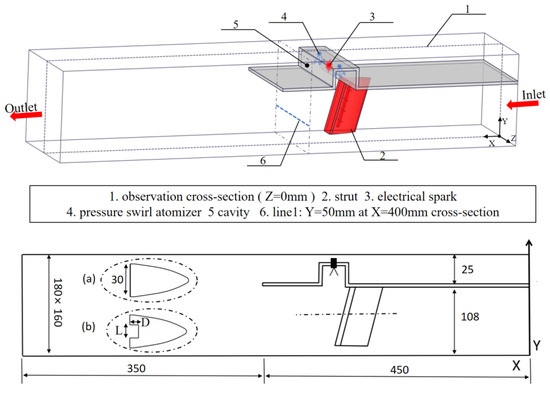
Figure 1.
The configuration of the simulation model. (a) Normal Strut. (b) Tail-groove Strut.
In this paper, with all other structural parameters held constant, this study primarily investigated the impact of the novel strut on combustion performance. The tail-groove strut is denoted by “”, where “” denotes the concave groove’s length and “” represents its width.
2.2. Flame Image-Processing Techniques
This paper proposes image-processing methods to extract and analyze flame features during the ignition process. Quantitative image-processing techniques are developed using MATLAB R2023a algorithms. The flow chart of these methods is shown in Figure 2. The algorithm consists of three core steps: image enhancement, image segmentation, and ignition process analysis.
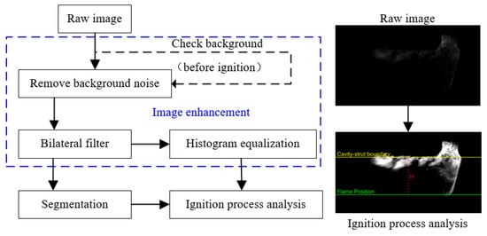
Figure 2.
Feature extraction of instantaneous flame in the ignition process.
The raw flame luminosity captured by the high-speed camera consists of a sequence of grayscale images with a range of [0, 255]. The first step of this method (image enhancement) is removing background noise. Before ignition, the background area in the image is marked as . The pixel value is denoted as . If falls within the region, the pixel value is set to zero, otherwise it remains unchanged. This can be expressed by the following equation:
Subsequently, image filtering is performed using a 2D bilateral, implemented via the ‘’ function and a smoothing kernel with and to enhance image quality and improve the signal-to-noise ratio. Then, to further enhance the visualization and analysis of flame structures, histogram equalization based on probability density functions was applied to linearly stretch the grayscale values.
In image segmentation, given the grayscale stretching affects the grayscale values, image segmentation is directly performed on the filtered image using a threshold value of 10.
After segmenting the image, pixels with grayscale values above 10, denoted as , are considered part of the flame. In the ignition process analysis, the lowest point along the y-axis of the flame is marked as the “Flame position”. The lowest y-coordinate, , is calculated as follows:
This “Flame position” is marked with a green line in Figure 2, while the “Cavity–strut boundary” is indicated by a red line. The distance between the flame position and the cavity–strut boundary is considered the radial flame distance, denoted as . This distance is calculated as follows: if , then ; if , then .
2.3. Experiment Set-Up
Figure 3 showcases an experimental set-up for studying the novel strut, consisting of air and fuel supply systems and two preheating systems with combustors. The strut, made from 304 stainless steel, was selected due to its excellent resistance to corrosion, high temperatures, and mechanical stress [27]. Injection pressure was regulated to maintain consistent fuel mass flow rates into the vitiated hot gas through stabilizing valves. The burner’s inlet conditions varied widely, including temperatures between 450 and 1200 K and velocities of 50–200 m/s, controlled by adjusting the mass flow rate, monitored by vortex flowmeters. Details on the test facility have been elaborated upon in our prior studies [28].
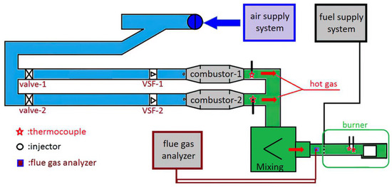
Figure 3.
Structure of experimental system.
The measurement system collected and recorded data in real-time using an acquisition card. Fuel mass flow rates were accurately measured using LZD-15 type intelligent metal tube flowmeters, with a precision error under 1.5% and a range of 1–200 g/s. Air mass flow rates were measured by LUGB-24 type vortex flowmeters, offering a range of 0.2–2.4 kg/s and accuracy of ±1.0%. K-type thermocouples measured inlet air temperatures, while B-type thermocouples determined flame temperatures. Species profiles were analyzed using the NOVAPlus multifunctional flue gas analyzer by MRU, with maximum permissible errors documented in our previous works [29,30].
The experimental image acquisition set-up, as illustrated in Figure 4, consists of a high-speed camera and computer. The imaging system uses a FASTCAM NOVA S9 camera manufactured by Photron (Tokyo, Japan), featuring a maximum adjustable resolution of 1024 × 1024 pixels, with a pixel size of 20 µm. The camera offers a maximum frame rate of 9000 fps at full resolution and has a memory capacity of 32 GB. The minimum exposure time is 1.05 µs, making it well suited for capturing combustion events. For imaging, a Nikon 50 mm fixed-focus lens is employed.
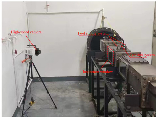
Figure 4.
Test facility.
2.4. Numerical Method
To assess the impact of flow patterns on ignition and flame stability across various strut configurations, numerical simulations were conducted on the specified geometric model using the Reynolds-averaged Navier–Stokes (RANS) code based on the finite volume solver of commercial platform Fluent22.2. A standard k–ε model was selected as a turbulence model, which has been verified to accurately simulate the flow characteristics in the combustor with the cavity–strut combustor without bypass flow [22]. A standard wall function method was utilized for processing the near wall. The coupling of pressure and velocity was accomplished through the SIMPLE (Semi-Implicit Method for Pressure-Linked Equations) algorithm.
The simulation employed the gas transport equation, incorporating discrete kerosene–air mixture terms into the previously mentioned geometric model. Combustion was modeled using the Eddy Dissipation Concept (EDC) model, coupled with the previously mentioned simplified reaction mechanism, which comprises 13 species and 16 reactions. The ambient pressure of the combustion chamber is 101,325 Pa, and detailed boundary conditions are shown in Table 1.

Table 1.
Boundary conditions.
To reduce the computational accuracy’s reliance on mesh size, this study used ICEM 2022a software for mesh generation and refined the junction between the strut and pilot to a size of 1 mm. Numerical calculations were carried out for computational domains with total mesh counts of 2.36 million, 3.56 million, 5.90 million, and 8.55 million. Figure 5 shows the axial velocity at line 1, as shown in Figure 1, where it is influenced by the complex vortex generated between the cavity zone and strut zone. It was found that different mesh sizes have little effect on calculation results. Thus, balancing computational resources and the need for sufficient data, numerical simulations are conducted with 5.9 million elements.
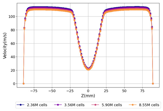
Figure 5.
Grid independence verification.
2.5. The Reaction Mechanism Employed
This study employed a further simplified reaction mechanism of C12H23, as shown in Table 2 and termed Mechanism_reduction, which consisted of 13 species and 16 reactions. This simplification was achieved by reducing the previously simplified reaction mechanism of C12H23, named Mechanism_initial, which included 16 species and 25 reactions [29]. To evaluate the effectiveness of the simplified reaction mechanism, Chemkin 2022R1 software was utilized to apply both mechanisms under the conditions of a sealed and homogeneously mixed constant-volume reaction, wherein the reaction of aviation kerosene with air was conducted under stoichiometric conditions. The comparison parameters were reactant mass, final temperature, pressure, and CO, H2O, and CO2 production.

Table 2.
C12H23 simplified reaction mechanism.
Figure 6 illustrates the correlation between the initial reaction temperature and comparison parameters. Computational findings show consistent trends in these parameters across both reaction mechanisms.
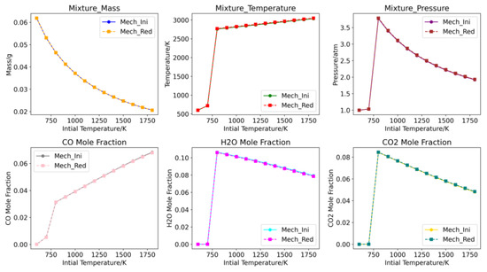
Figure 6.
Comparison of the results via Mech_Ini and Mech_Red.
Following this, an error analysis was conducted. Error values serve as direct indicators of rationality, stability, and fidelity in the process of simplifying mechanisms. The removal of non-essential elementary reactions during simplification inevitably introduces computational errors. To understand the disparities in calculations between simplified and initial mechanisms, we define the computational error of the simplified mechanism as follows:
As depicted in Figure 7, the final temperature, final pressure, and CO2 concentration of the simplified mechanism were found to be lower than their initial values, whereas the concentrations of H2O and CO increased, and the mass of reactants remaining was unchanged. The conversion between CO and carbon CO2 serves as the principal reaction for heat generation. The amount of CO2 produced by the simplified mechanisms was lower compared to the initial mechanism, resulting in a slight decrease in the final temperature and pressure.
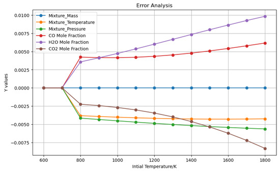
Figure 7.
Error analysis of the results via Mech_Ini and Mech_Red.
The computational analysis indicated that variations in reactant mass, final temperature, pressure, and CO concentration were below 0.6%, with a maximum deviation for H2O and CO2 under 1%. This error analysis demonstrates that the simplified reaction mechanism retains substantial accuracy and reliability.
3. Results and Discussion
3.1. Dynamic Ignition Process
3.1.1. Numerical Validation
Experimental observations were conducted to validate the numerical simulations of the ignition process. The results, presented in Figure 8, illustrate a sequence of events over a 25 ms frame, showing the development of the flame kernel from its initial formation to a fully developed flame under conditions of 700 K and 100 m/s. The ignition process can be categorized into four main stages: (1) kernel generation, (2) kernel propagation, (3) flame refilling, and (4) flame growth.
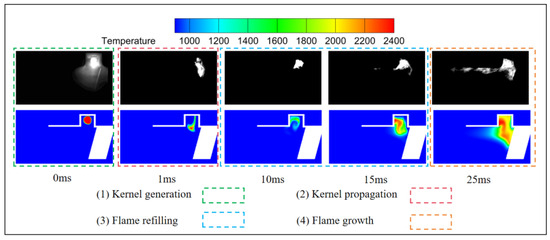
Figure 8.
Ignition process using CFD and high-speed camera.
At 0 ms, ignition begins with an electrical spark, marking the kernel generation stage. The kernel then rapidly propagates towards the region behind the strut. However, due to the insufficient spark energy to ignite the unburned gases in this region and the influence of the recirculation zone within the cavity, a flame-refilling process occurs. This refilling process involves the flame reoccupying the cavity, which provides a stable environment for further development. In the subsequent flame growth stage, the flame, having fully developed within the cavity, starts to propagate towards the region behind the strut.
Figure 9 illustrates the radial flame distance during the ignition process. To quantitatively assess the radial flame propagation performance under different strut configurations, temperature thresholds of 1600 K, 1700 K, and 1800 K were evaluated. The results indicate that the numerical simulations for all three temperature thresholds closely match the experimental data.
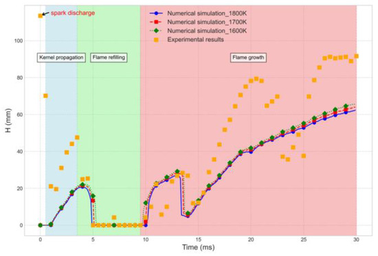
Figure 9.
The radial flame distance using CFD.
In the kernel generation stage, the electrical spark induces a peak in the radial flame distance, which rapidly declines. During kernel propagation, the flame expands rapidly, leading to an increase in radial flame distance in both experimental and numerical results. In the flame-refilling stage, this distance drops sharply and remains stable for a short period. Finally, in the flame growth stage, the radial flame distance gradually increases again as the flame fully develops. In this study, 1800 K was selected as the temperature threshold for analysis.
3.1.2. Flame-Propagation Performance
The ignition processes in the tail-groove strut across five configurations, along with a normal strut, were investigated to gain a deeper understanding of how these configurations influence ignition characteristics. As discussed in Section 3.1.1, a temperature threshold of 1800 K was selected as the criterion for successful flame propagation. Figure 10 and Figure 11 compare the effects of the and parameters on flame propagation performance in cavity-based integrated combustors, with operating conditions set at and .
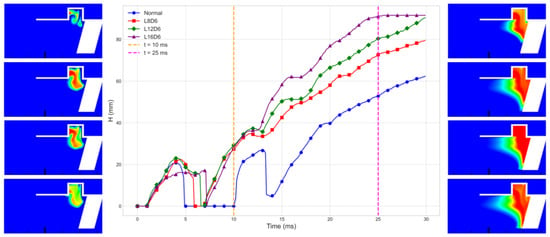
Figure 10.
The radial flame distance and the instantaneous temperature contour plot at Z = 0 mm, as shown in Figure 1. From top to bottom, the configurations are as follows: Normal, , , and .
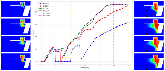
Figure 11.
The radial flame distance and the instantaneous temperature contour plot at Z = 0 mm, as shown in Figure 1. From top to bottom, the configurations are as follows: Normal, , , and .
The figure reveals that the tail-groove strut designs achieve greater flame propagation distances compared to the normal strut. Specifically, in the case of the configuration, the flame reaches the root of the radial stabilizer within 25 ms. In contrast, the flame in the normal strut configuration has not yet reached the radial stabilizer root, even after 30 ms. Furthermore, an increase in the length and of the tail-groove strut correlates with a higher radial flame propagation performance. This improvement is attributed to the reduced flame refilling duration, which enhances the overall efficiency of flame propagation.
Notably, Figure 11 shows that increasing D from 8 mm to 10 mm does not affect the radial flame propagation performance, indicating the existence of a critical depth, . Beyond this critical depth, further increases in do not affect the radial flame propagation performance. Additionally, a comparison of the and configurations reveals that, despite having the same tail-slot volume, their radial flame propagation performances differ. When compared to the configuration, increasing is found to accelerate the flame propagation rate more effectively than increasing . Specifically, the configuration completes flame propagation in 25 ms, whereas the configuration achieves this in 23 ms.
At , it is observed that, as increases, the temperature of the flame core decreases, although the flame area remains unchanged. This is due to the larger tail-slot volume requiring more heat to fill, leading to a lower core temperature. In contrast, increasing results in a decrease in flame area but an increase in core temperature. The implications of these changes will be further discussed in the following section, focusing on the flow field characteristics.
3.2. The Flow Characteristics
Considering the same operating conditions, the ignition performance is mainly influenced by the following flow characteristics. To better understand the variations in ignition performance, numerical simulations were conducted to analyze the flow patterns and turbulent kinetic energy (k). Figure 12 presents the corresponding results. The figure shows that in the normal strut configuration, two distinct recirculation zones are observed: recirculation A within the cavity and recirculation C at the root of the strut. The airflow in the cavity region is directed towards the area behind the strut due to its influence.
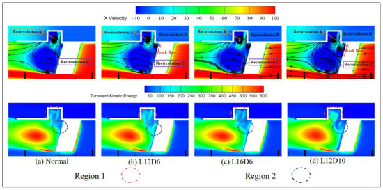
Figure 12.
Flow patterns and turbulent kinetic energy.
In contrast, the tail-groove strut configuration features three distinct recirculation zones: recirculation A within the cavity, recirculation B at the junction between the cavity and the strut, and recirculation C at the root of the strut. This is due to the concave wall surface of the tail-groove strut, which constrains the airflow near the wall, causing some of it to flow radially. Additionally, the pressure gradient induces backflow, which subsequently leads to the formation of recirculation B.
Recirculation B enhances the breakup and atomization of fuel droplets in this region, which improves radial flame propagation performance. Additionally, recirculation B acts as a transitional zone for radial flame propagation, allowing energy accumulation in this area, which in turn boosts the flame’s radial propagation. This explains why the tail-groove strut reduced the flame refilling duration.
As the length increases from to , the turbulent kinetic energy in regions 1 and 2, as shown in Figure 12, correspondingly decreases. This reduction in turbulent kinetic energy diminishes the intensity of mixing between the flame and the unburned fuel. Additionally, as L increases, backflow is noticeably diminished and eventually disappears. This can be attributed to the reduced restriction on the near-wall airflow by the concave wall surface of the tail-groove strut, which weakens the radial flow at Z = 0 mm. Furthermore, the alteration in the pressure field also plays a crucial role in the elimination of backflow. The disappearance of backflow results in a concomitant reduction in heat exchange capacity. Consequently, at , the temperature of the flame core in the configuration decreases.
As the depth increases from to , the turbulent kinetic energy in region 1 increases, while it decreases in region 2. The increase in turbulence in region 1 enhances the mixing and interaction between the flame and the unburned fuel, leading to a more extensive flame area. However, in region 2, the decrease in turbulence reduces the mixing intensity, leading to a smaller flame area. Additionally, the increase in depth causes a larger recirculation zone B, as the radial flow at the Z = 0 plane is enhanced. This change in turbulence distribution leads to a reduction in the overall flame area while simultaneously increasing the temperature of the flame core.
4. Conclusions
This study provides an in-depth analysis of ignition processes and flame propagation performance in cavity-based integrated combustors, focusing on the effects of various tail-groove strut configurations. The main results are summarized below:
- (1)
- The ignition process was successfully validated through comparisons of numerical simulations with experimental observations. This study identified and categorized the ignition process into four distinct stages: kernel generation, kernel propagation, flame refilling, and flame growth.
- (2)
- The tail-groove strut configurations demonstrate superior flame propagation distances compared to the normal strut, which is attributed to reductions in the flame refilling duration.
- (3)
- The tail-groove strut features three recirculation zones—A, B, and C—compared to two in the normal strut. Recirculation B significantly enhances fuel droplet breakup and atomization, improving radial flame propagation and reducing the flame refilling duration.
- (4)
- Increasing the strut length () from to lowers the turbulent kinetic energy, reducing the flame core temperature. Conversely, increasing from to boosts the turbulent kinetic energy in specific areas, reducing the flame area but raising the flame core temperature.
Author Contributions
Conceptualization, S.Z. and H.C.; Methodology, S.Z. and H.C.; Software, H.C.; Writing—original draft, H.C. All authors have read and agreed to the published version of the manuscript.
Funding
This research was funded by the Aero Engine Corporation of China, grant number HFZL2023CXY003 and Shenzhen Science and Technology Program (Grant No. RCBS20221008093126068).
Institutional Review Board Statement
Not applicable.
Informed Consent Statement
Not applicable.
Data Availability Statement
The data presented in this study are available on request from the corresponding author. The data are not publicly available due to privacy restrictions.
Conflicts of Interest
The authors declare no conflicts of interest.
References
- Chen, M.; Tang, H.; Zhang, K.; Hui, O.; Wang, Y. Turbine-based combined cycle propulsion system integration concept design. Proc. Inst. Mech. Eng. Part G J. Aerosp. Eng. 2013, 227, 1068–1089. [Google Scholar] [CrossRef]
- Zhu, Z.; He, X.; Xue, C.; Hong, L.; Zhu, Y.; Song, Y. Experimental investigations on combustion characteristics of a cavity pilot augmentor of the turbine-based combined cycle engine. Proc. Inst. Mech. Eng. Part G J. Aerosp. Eng. 2015, 229, 2024–2034. [Google Scholar] [CrossRef]
- Ma, J.; Chang, J.; Ma, J.; Bao, W.; Yu, D. Mathematical modeling and characteristic analysis for over-under turbine based combined cycle engine. Acta Astronaut. 2018, 148, 141–152. [Google Scholar] [CrossRef]
- Zhang, T.; Wang, Z.; Huang, W.; Chen, J.; Sun, M. The overall layout of rocket-based combined-cycle engines: A review. J. Zhejiang Univ.-Sci. A 2019, 20, 163–183. [Google Scholar] [CrossRef]
- Shi, L.; Zhao, G.; Yang, Y.; Gao, D.; Qin, F.; Wei, X.; He, G. Research progress on ejector mode of rocket-based combined-cycle engines. Prog. Aerosp. Sci. 2019, 107, 30–62. [Google Scholar] [CrossRef]
- Sziroczak, D.; Smith, H. A review of design issues specific to hypersonic flight vehicles. Prog. Aerosp. Sci. 2016, 84, 1–28. [Google Scholar] [CrossRef]
- Cai, Z.; Sun, M.; Wang, Z.; Bai, X.-S. Effect of cavity geometry on fuel transport and mixing processes in a scramjet combustor. Aerosp. Sci. Technol. 2018, 80, 309–314. [Google Scholar] [CrossRef]
- Miao, J.; Fan, Y.; Wu, W.; Zhao, S. Effect of preheated fuel supply by gas reflux on thermodynamic characteristics in a cavity-based integrated combustor. Aerosp. Sci. Technol. 2021, 108, 106352. [Google Scholar] [CrossRef]
- Mancilla, P.C.; Chakka, P.; Acharya, S. Performance of a trapped vortex spray combustor. In Proceedings of the Turbo Expo: Power for Land, Sea, and Air, New Orleans, LA, USA, 4–7 June 2001. [Google Scholar]
- Huang, W.; Du, Z.; Yan, L.; Moradi, R. Flame propagation and stabilization in dual-mode scramjet combustors: A survey. Prog. Aerosp. Sci. 2018, 101, 13–30. [Google Scholar] [CrossRef]
- Barnes, F.W.; Segal, C. Cavity-based flameholding for chemically reacting supersonic flows. Prog. Aerosp. Sci. 2015, 76, 24–41. [Google Scholar] [CrossRef]
- Li, Q.; Pan, Y.; Tan, J.; Wang, Z. Comparison of characteristics of ramjet with cavity-based flame holder and V-gutter flame holder. J. Aerosp. Power 2010, 25, 35–40. [Google Scholar] [CrossRef]
- Stallings, R.; Wilcox, F. Experimental Cavity Pressure Distributions at Supersonic Speeds; Nasa Tp; NASA: Washington, DC, USA, 1987. [Google Scholar]
- Nayal, S.; Lamb, S.; Sahoo, D.; Raghavendra, N.V.; Bellary SA, I. Computational analysis of novel cavity-based flameholder designs for supersonic combustion engines. In IOP Conference Series: Materials Science and Engineering; IOP Publishing: Bristol, UK, 2020; Volume 814, p. 012018. [Google Scholar]
- Moradi, R.; Mahyari, A.; Gerdroodbary, M.B.; Abdollahi, A.; Amini, Y. Shape effect of cavity flameholder on mixing zone of hydrogen jet at supersonic flow. Int. J. Hydrogen Energy 2018, 43, 16364–16372. [Google Scholar] [CrossRef]
- Zhang, R.; Huang, X.; Fan, W.; Bai, N. Influence of injection mode on the combustion characteristics of slight temperature rise combustion in gas turbine combustor with cavity. Energy 2019, 179, 603–617. [Google Scholar] [CrossRef]
- Zhao, Y.; Fan, W.; Zhang, R. Influence of coupling schemes of radial and circumferential flame stabilization modes on flow and combustion characteristics of compact combustion for gas turbine. Fuel 2023, 333, 126543. [Google Scholar] [CrossRef]
- Sun, M.B.; Wang, Z.G.; Liang, J.H.; Geng, H. Flame characteristics in supersonic combustor with hydrogen injection upstream of cavity flameholder. J. Propuls. Power 2008, 24, 688–696. [Google Scholar] [CrossRef]
- Hsu, K.Y.; Carter, C.D.; Gruber, M.R.; Barhorst, T.; Smith, S. Experimental study of cavity-strut combustion in supersonic flow. J. Propuls. Power 2010, 26, 1237–1246. [Google Scholar] [CrossRef]
- Wang, Y.M.; Fang, X.J.; Lin, P.; Gu, H.B.; Wang, X.; Tao, J.X. Performance of ramjet combustor based on cavity/strut structure. J. Aerosp. Power 2017, 32, 2355–2363. [Google Scholar]
- Miao, J.; Fan, Y.; Liu, T. Influence of strut on cavity at subsonic speeds: Ignition characteristics. Proc. Inst. Mech. Eng. Part G J. Aerosp. Eng. 2020, 234, 1369–1379. [Google Scholar] [CrossRef]
- Miao, J.; Fan, Y. Influence of struts on cavity at subsonic speeds: Flow characteristics. Proc. Inst. Mech. Eng. Part G J. Aerosp. Eng. 2019, 233, 5369–5379. [Google Scholar] [CrossRef]
- Miao, J.; Fan, Y.; Wu, W.; Zhao, S. Effect of air-assistant on ignition and flame-holding characteristics in a cavity-strut based combustor. Appl. Energy 2021, 283, 116307. [Google Scholar] [CrossRef]
- Miao, J.; Fan, Y.; Wu, W.; Zhao, S. Influence of air-entraining intensity on the afterburner ignition, flame-holding and combustion characteristics. Aerosp. Sci. Technol. 2020, 106, 106063. [Google Scholar] [CrossRef]
- Zhao, S.; Fan, Y. Experimental and numerical study on fuel distribution and flame expansion of the enhanced flame holding devices. Energy 2020, 203, 117850. [Google Scholar]
- Zhao, S.; Xiao, H.; Li, Y. Research on the Ignition Process and Flame Stabilization of a Combination of Step and Strut: Experimental and Numerical Study. Energies 2023, 16, 2832. [Google Scholar] [CrossRef]
- Stojanović, B.Ž.; Milojević, S.T. Characterization, manufacturing and application of metal matrix composites. In Advances in Materials Science Research; Wythers, M.C., Ed.; Nova Science Publishers: New York, NY, USA, 2017; Volume 30, pp. 83–113. [Google Scholar]
- Zhao, S.; Fan, Y. Analysis of flow resistance and combustion characteristics in the combined application of step and strut. Aerosp. Sci. Technol. 2020, 98, 105676. [Google Scholar] [CrossRef]
- Xiao, H.; Zhao, S.; Li, Y.; Chen, H.; Xie, L. Influence of time-varying flow on dynamic flame characteristics in VCE: Numerical and experimental study. Appl. Therm. Eng. 2024, 236, 121651. [Google Scholar] [CrossRef]
- Smooke, M.D. (Ed.) Reduced Kinetic Mechanisms and Asymptotic Approximations for Methane-Air Flames: A Topical Volume; Springer: Berlin, Germany, 1991. [Google Scholar]
Disclaimer/Publisher’s Note: The statements, opinions and data contained in all publications are solely those of the individual author(s) and contributor(s) and not of MDPI and/or the editor(s). MDPI and/or the editor(s) disclaim responsibility for any injury to people or property resulting from any ideas, methods, instructions or products referred to in the content. |
© 2024 by the authors. Licensee MDPI, Basel, Switzerland. This article is an open access article distributed under the terms and conditions of the Creative Commons Attribution (CC BY) license (https://creativecommons.org/licenses/by/4.0/).