Article

Seismic Wave Amplification Characteristics in Slope Sections of Various Inclined Model Grounds

Department of Civil Engineering, Chosun University, Gwangju 61452, Republic of Korea
*
Author to whom correspondence should be addressed.
Appl. Sci. 2024, 14(19), 9014; https://doi.org/10.3390/app14199014
Submission received: 19 August 2024 / Revised: 27 September 2024 / Accepted: 4 October 2024 / Published: 6 October 2024
(This article belongs to the Special Issue Slope Stability and Earth Retaining Structures—2nd Edition)

Abstract

:
The collapse of slopes caused by earthquakes can lead to landslides, resulting in significant damage to both lives and structures. Seismic reinforcement of these slopes can protect social systems during an earthquake. In South Korea, where more than 70% of the land is mountainous, the stability of slopes is of paramount importance compared to other countries. While many seismic designs are based on peak ground acceleration (PGA), there is relatively little consideration given to the extent of PGA’s influence, and few studies have been done. This study aims to assess the seismic amplification of slopes with multilayers using a 1 g shaking table and verify the results through numerical analysis after confirming the impact of PGA at specific points. Typically, slope model experiments are conducted on single-layered ground models. However, actual ground conditions consist of multiple layers rather than a single layer, so a multi-layered model was created with different properties for the upper and lower layers. Two multi-layered ground models consisting of two layers were created, one with a flat ground surface and the other with a sloped surface. The properties of the two layers in each model were configured as a single layer to create the slope models. The peak ground acceleration (PGA) of the four ground models was compared, revealing that seismic wave amplification increases as it moves upward, and the amplification is even greater when transitioning from the lower to the upper ground layers, leading to different dynamic behavior of the slope. Through the contour lines, the influence of PGA was further confirmed, and it was found that approximately 60% of the PGA impact occurs at the topmost part of the slope on average. Analysis of the earthquake waves showed that the top of the slope experienced an average amplification of about 31.75% compared to the input motion, while the lower part experienced an average amplification of about 27.85%. Numerical analysis was performed using the ABAQUS program, and the results were compared with the 1 g shaking table experiments through spectral acceleration (SA), showing good agreement with the experimental results.

1. Introduction

Many damages are caused by earthquakes, and a significant portion of these are due to the collapse or destruction of slopes. Dynamic loads on the ground, such as those from earthquakes, lead to slope collapses or landslides in inclined lands like embankments, landfills, and mountain slopes. These events can cause extensive damage to human life and structures, affecting numerous infrastructures essential for daily life, such as roads, thereby significantly impacting social systems. For instance, the 1964 Alaska earthquake caused large-scale slope collapses over an area of 269,000 km2. Additionally, the magnitude 7.9 earthquake in Peru resulted in the largest slope collapse in recorded history, causing more than 18,000 fatalities and triggering thousands of slope collapses over an area of 30,000 km2 [1].
In Republic of Korea, the 2016 Gyeongju earthquake and the 2017 Pohang earthquake caused landslides due to slope collapses, resulting in significant damage. Given that over 70% of Republic of Korea’s land is mountainous, it is predicted that without ensuring seismic stability of slopes, more severe damage will occur during earthquakes. This has highlighted the necessity for research and development to prevent landslide damage caused by slope collapses in South Korea [2,3,4,5]. However, it is difficult to accurately predict the amplification characteristics in three-dimensional topographies like slopes compared to horizontal ground [6,7,8,9]. Therefore, various studies have been conducted to evaluate the stability of slopes and determine amplification characteristics. In general, the dynamic behavior characteristics of such slopes have primarily been analyzed through numerical analysis. However, unlike numerical analysis, dynamic behavior experiments conducted by constructing model grounds are considered more effective as they provide an intuitive understanding of behavior characteristics [10]. Dynamic behavior experiments are mainly performed using 1 g shaking tables and centrifuge model equipments, and the validity of these experiments has been verified by various researchers through comparisons with numerical analyses [11,12,13,14]. Using these validated dynamic behavior experiments, many researchers have constructed various slope models to analyze the dynamic behavior characteristics of slope grounds. Evaluations of the dynamic behavior characteristics of model slopes using 1 g shaking tables have been conducted by creating models with various slope angles. These model slopes have mainly been analyzed through Peak Ground Acceleration (PGA), Amplification Factor, and Spectral Acceleration (SA). The slope shapes were constructed with various convex and concave surfaces to analyze acceleration amplification. It was observed that the type of slope affects the dynamic response; for example, in concave slopes, shoulder collapse, formation of the sliding surface, and integral sliding above the slope line occurred, while in convex slopes, internal sliding within the soil layer and slope failure near the slope line were primarily observed [11,15]. Additionally, studies have been conducted to understand the behavior characteristics of reinforced model slopes using piles or geogrids. For example, Park [16] studied the behavior characteristics of slopes reinforced with soil nails under head restraint using a 1 g shaking table, and found that after reinforcement with soil nails, there was a reduction in upper slope settlement, horizontal and vertical displacement at the front, and acceleration amplification, thus improving slope stability during earthquakes. Srilatha et al. [17] conducted experiments on the model ground before and after reinforcement with geogrids across different frequency ranges, concluding that the reinforced model was less affected by frequency, whereas the unreinforced model was significantly influenced by frequency, playing a crucial role in seismic response. Hongqiang et al. [18] analyzed the acceleration amplification effect, dynamic earth pressure, and dynamic bending moment after constructing a model slope reinforced with anchor-reinforced pile structures. The study found that as the elevation increased, acceleration amplification also increased, and that ground motion variability did not significantly alter the distribution pattern of dynamic earth pressure. While many researchers have studied the dynamic behavior characteristics by creating various model grounds, including changes in geometric slope shapes, variations in relative density, and reinforcement of model slopes using shaking tables, most studies have focused on the dynamic behavior characteristics of single-layer grounds. However, real slope grounds are composed of complex structures with multiple layers, rather than single-layered ground.
Recently, several studies have made advancements in understanding the dynamic behavior of slopes under seismic conditions. Zhang et al. [19] explored the overturning resistance performance of friction pendulum bearing (FPB) isolated structures under seismic actions, showing how soil-structure interaction and factors like displacement ratio and friction coefficient significantly influence overturning resistance. Liu et al. [20] investigated wedge failure in rock slopes using 3D discontinuous deformation analysis (DDA), providing insights into wedge stability and post-failure block movements. Similarly, Du and Wang [21] proposed a probabilistic seismic displacement analysis framework for spatially distributed slope systems, emphasizing the importance of spatial correlations in ground motion intensity measures when evaluating slope displacement hazards.
In this study, the dynamic behavior characteristics of single slope model grounds, multi-layer flat model grounds, and multi-layer slope model grounds were analyzed using a 1 g shaking table. For the single slope ground, model grounds were created using the same material with varying relative densities. The multi-layer model grounds were constructed with two layers, each layer reflecting the characteristics of the individual grounds. The dynamic behavior characteristics of the multi-layer model grounds were compared between slope and flat configurations. Additionally, numerical simulations were conducted to validate the experimental results obtained from the shaking table. The numerical simulations used the two-dimensional finite element analysis program Abaqus. The experimental data and numerical simulation data were compared for validation.

2. Experimental Method for Model Ground Using Shaking Table

2.1. Expermental Equipment

Figure 1 shows the 1 g shaking table and the Laminar Shear Box (LSB) used in this experiment. The LSB was placed on the 1 g shaking table, and the model ground was constructed inside it. The LSB allows for layer shear, enabling each layer to move during shaking with the input seismic waves, thereby minimizing boundary effects during the experiment. The dimensions of the LSB are 2000 mm (width) × 600 mm (length) × 600 mm (height), with each layer being 50 mm thick, comprising a total of 12 layers. Ball bearings were used between the layers to minimize friction, and rubber packing was employed to absorb impact. Each layer can move independently with a maximum displacement of 5 mm.

2.2. Physical Properties of Weathered Soil Specimens

In this study, experiments were conducted using weathered soil samples collected from the field. Table 1 shows the physical properties of the weathered soil samples used in the model ground. The following values were derived from basic physical property tests on the field-collected samples: the specific gravity ( G s ) of the sample is 2.65, the minimum void ratio ( e m i n ) is 0.64, the maximum void ratio ( e m a x ) is 1.06, and the internal friction angle is 38°. The mean particle size ( d 50 ) is 0.235 mm, the coefficient of curvature ( C c ) is 1.03, and the coefficient of uniformity ( C u ) is 1.76, classifying the sample as SP (poorly graded sand) according to the Unified soil classification system (USCS).

2.3. Input-Motion

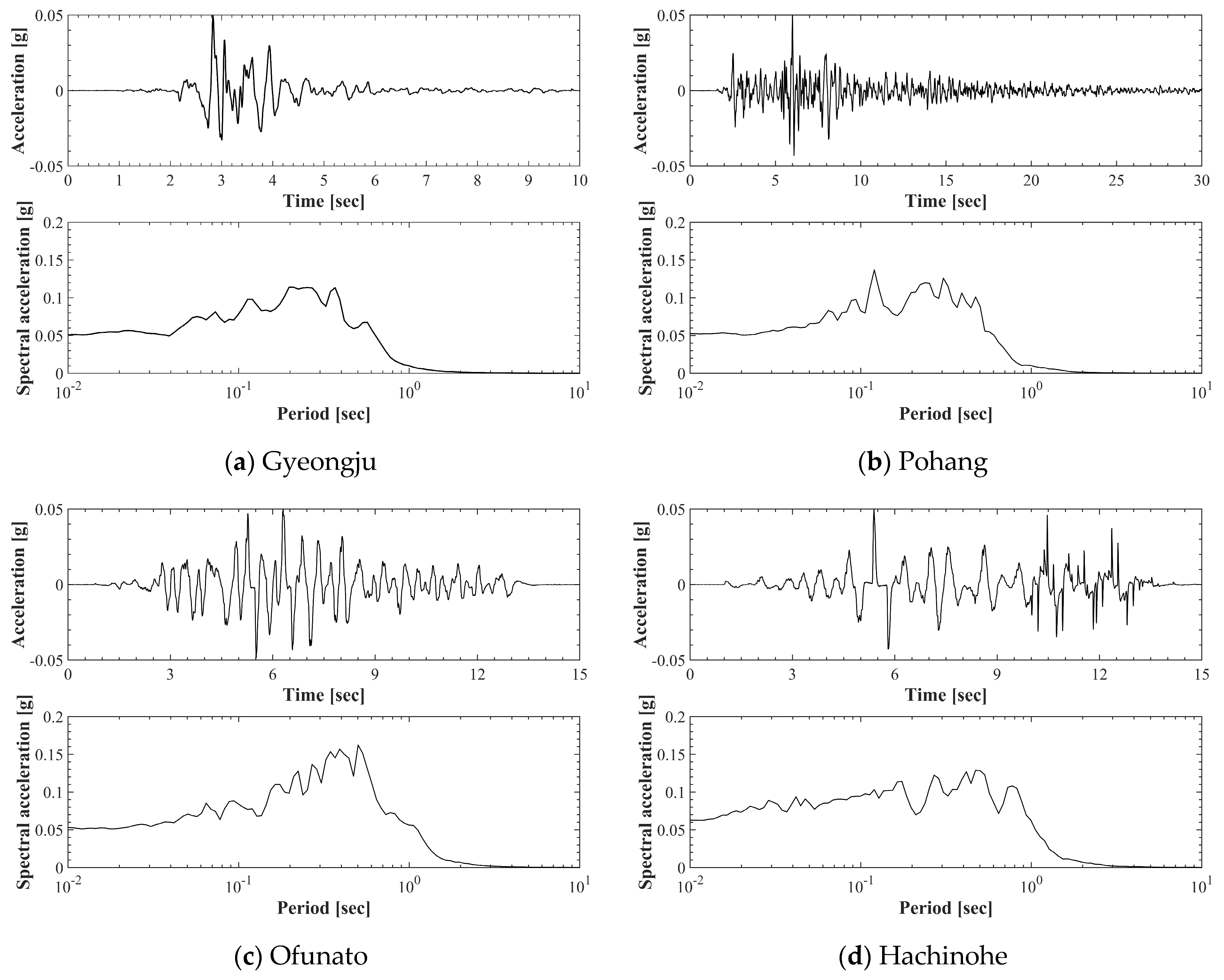
Figure 2 shows the input seismic waves used for the shaking. Four different seismic waves were used, each adjusted to a scale of 0.05 g for application to the model ground. Figure 2a is the seismic wave actually measured in the Gyeongju region of Republic of Korea in 2016, and Figure 2b is the seismic wave measured in the Pohang region in 2017. Figure 2c,d are the Ofunato and Hachinohe waves, respectively, which are commonly used in seismic design. Each seismic wave contains both short-period and long-period components.

2.4. Ground Models

Figure 3 shows the constructed ground models. A total of four ground models were created for the experiment. Figure 3a,b are single ground models with a 1:1 slope. They were constructed with relative densities of 75% (Case 1) and 85% (Case 2) respectively, initially created as flat models and then cut to form slope ground models. Figure 3c,d are multi-layer ground models. Each consists of two layers with different relative densities. The lower layer was constructed with the relative density of Case 2, and the upper layer with the relative density of Case 1. The moisture content of the ground models was set to 12.5%, which is the optimum moisture content (OMC) of the samples. The slopes were created with a depth of 200 mm, forming a basin shape. Although the LSB helps significantly reduce reflected waves generated during shaking, the slope was created 600 mm away from the edge to further minimize the effect of any remaining reflected waves. The depth of the slope was designed to be 200 mm to clearly transmit the effects of seismic wave amplification from the lower layer to the inclined surface of the upper layer during shaking.
The accelerometers were placed at the bottom of the soil box to measure the Bedrock motion, and for the measurement of shear wave velocity of the model ground, accelerometers AS1 to AS5 were placed at 100 mm intervals from the bottom of the soil box. To identify the differences in acceleration amplification at the slope section, accelerometers AS11 to AS13 were embedded at 75 mm intervals. Additionally, to observe the changes in acceleration amplification at the lower part of the slope, accelerometers AS14 to AS16 were embedded at 100 mm intervals from the bottom of the soil box.

3. Analysis of 1 g Shaking Table Experiment Results

3.1. Comparative Analysis of Acceleration Amplification

The analysis was conducted using the acceleration data measured by the accelerometers in each ground model. The PGA (Peak Ground Acceleration) analysis was performed by dividing the measurement points into two categories: slope section and vertical direction. The PGA amplification ratio was then determined in comparison with the seismic waves measured at the Bedrock. Additionally, contour plots were drawn and analyzed using the PGA data of the peak points measured by all embedded accelerometers.

3.1.1. Slope Section PGA

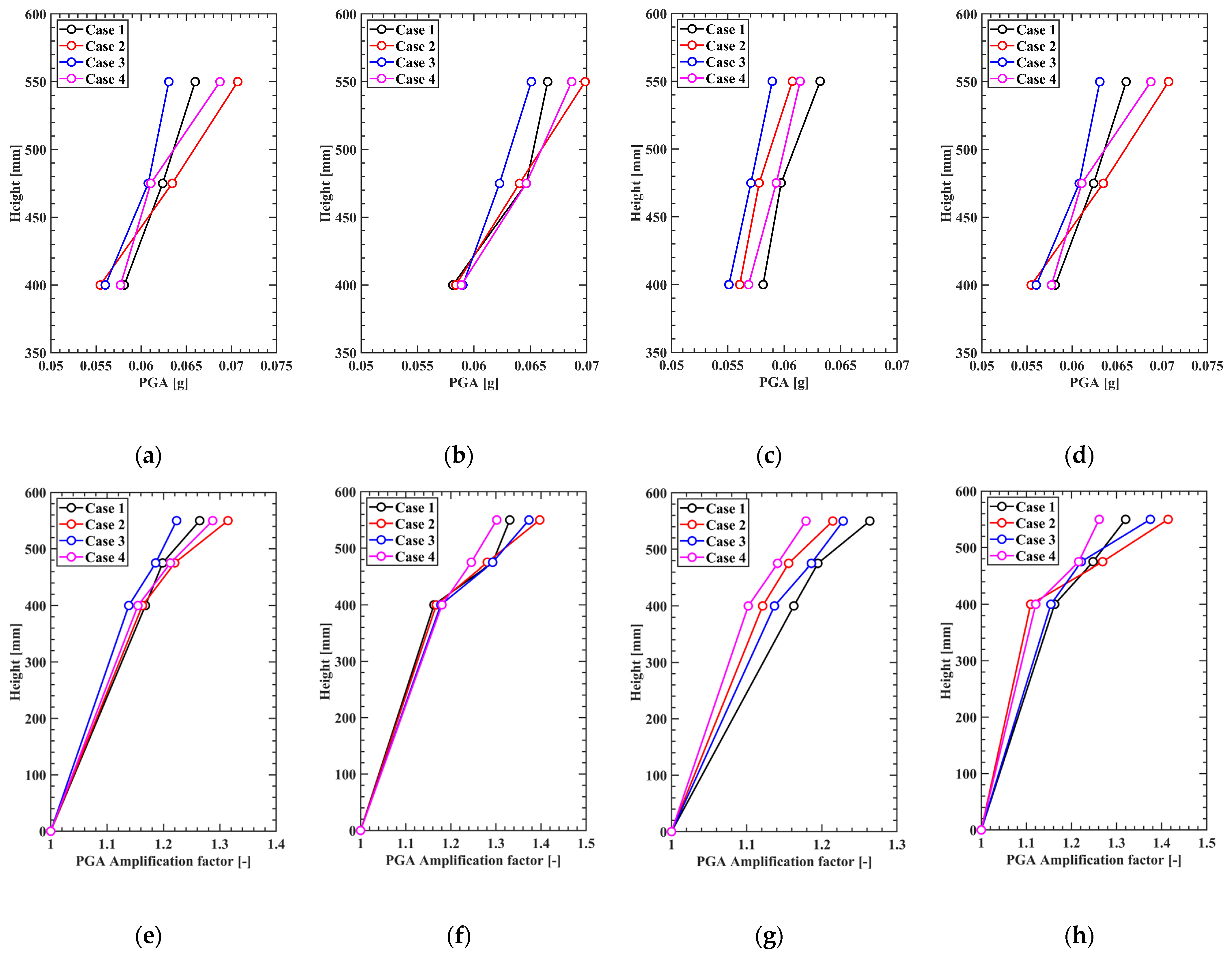
Figure 4 shows the Peak Ground Acceleration (PGA) measured by the accelerometers (AS11, 12, 13) in the slope section of the four model grounds. It can be observed that in all four model grounds, the PGA increases towards the upper part of the slope, with Case 3 showing less amplification compared to the other models with slopes. Figure 4d,e compare the input motion with the PGA at the measurement points to evaluate the amplification of seismic PGA. In the lower part of the slope, Case 3 showed a 13% amplification, while Case 2 showed about a 16% amplification, resulting in a difference of approximately 3%. However, in the upper part, Case 3, which had the smallest amplification, showed a 22% increase, while Case 2, with the largest amplification, showed a 31% increase. The largest amplification was observed in Case 1, which had the lowest relative density. Amplification was observed in the following order: Case 4, where the lower and upper parts had different relative densities, Case 2, with the highest relative density, and Case 3, the flat model ground.

3.1.2. Vertical PGA of Model Grounds

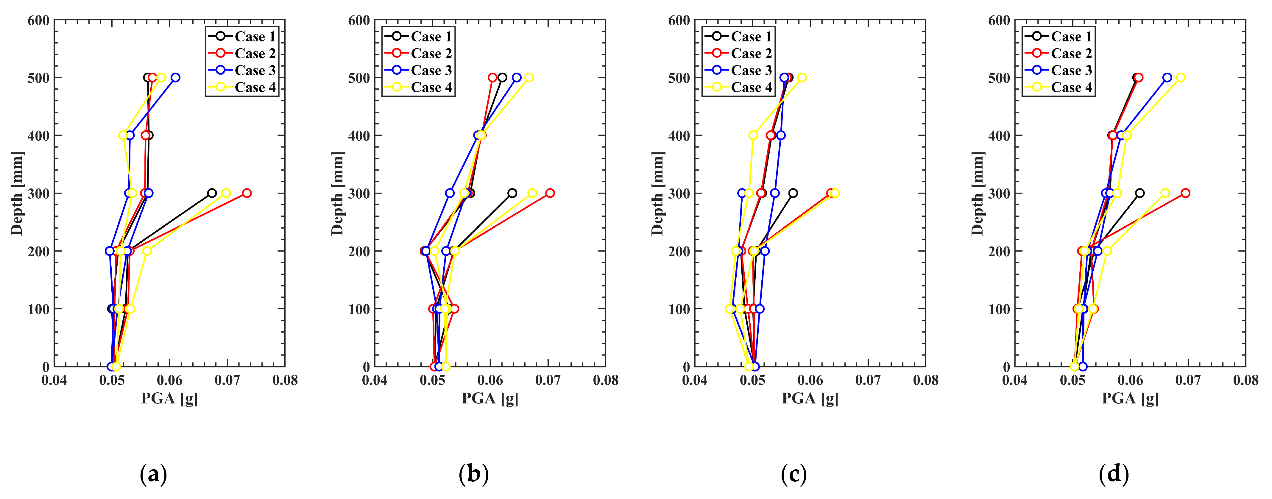
The PGA of each model ground was illustrated using the accelerometers vertically embedded for measurement, as shown in Figure 5a–d. It was observed that in all model grounds, the acceleration consistently amplified towards the upper part. However, the acceleration measured at the lower part of the slope (AS 14–16) displayed a different pattern compared to the other vertically measured PGAs. In the lower slope area (AS 14–16), except for the flat model ground in Case 3, the other model grounds showed a higher PGA at the AS 16 point, which was distinct from the PGAs at the same depth. The highest PGA was observed in Case 1, which had the lowest relative density, followed by Case 4 (2-layer model ground) and Case 2 with the highest relative density, indicating that the lower part of the slope experienced higher PGA. The lower amplification in Case 3 compared to the other model grounds is believed to be due to the effects of confining pressure, which resulted in less amplification.
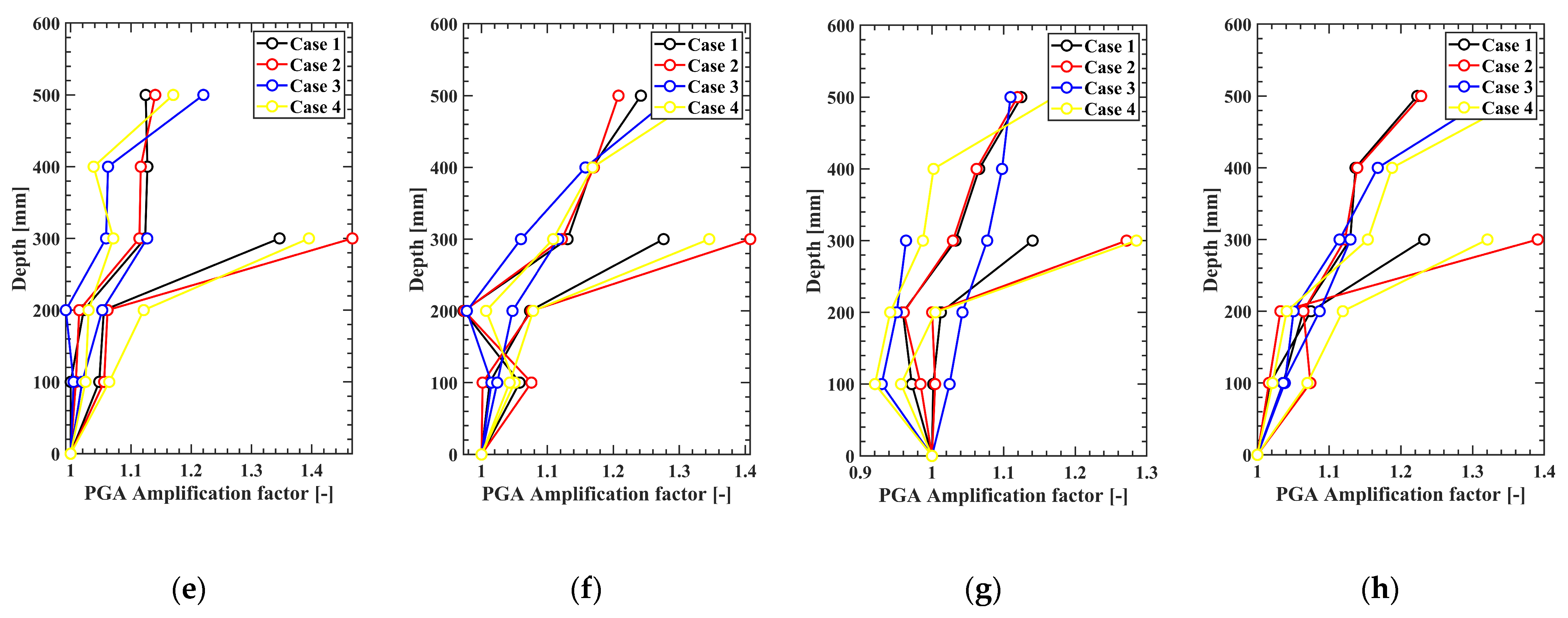
Additionally, by dividing the maximum ground acceleration (PGA) of the input motion by the PGA measured at each point, the seismic amplification factor was calculated. This allowed us to assess how much the seismic waves were amplified at each point compared to the input motion, as shown in Figure 5e–h. The amplification ratio analysis revealed that in the flat model ground of Case 3, the lower slope area amplified similarly to other points at the same height. However, in the other model grounds with slope formations, significant amplification occurred at the same height. The seismic amplification observed in the model grounds, as shown in Figure 5, indicates that large seismic amplifications can occur in the lower part of the slope during an earthquake, highlighting the necessity of seismic design considerations not only for the slope but also for the lower part of the slope.

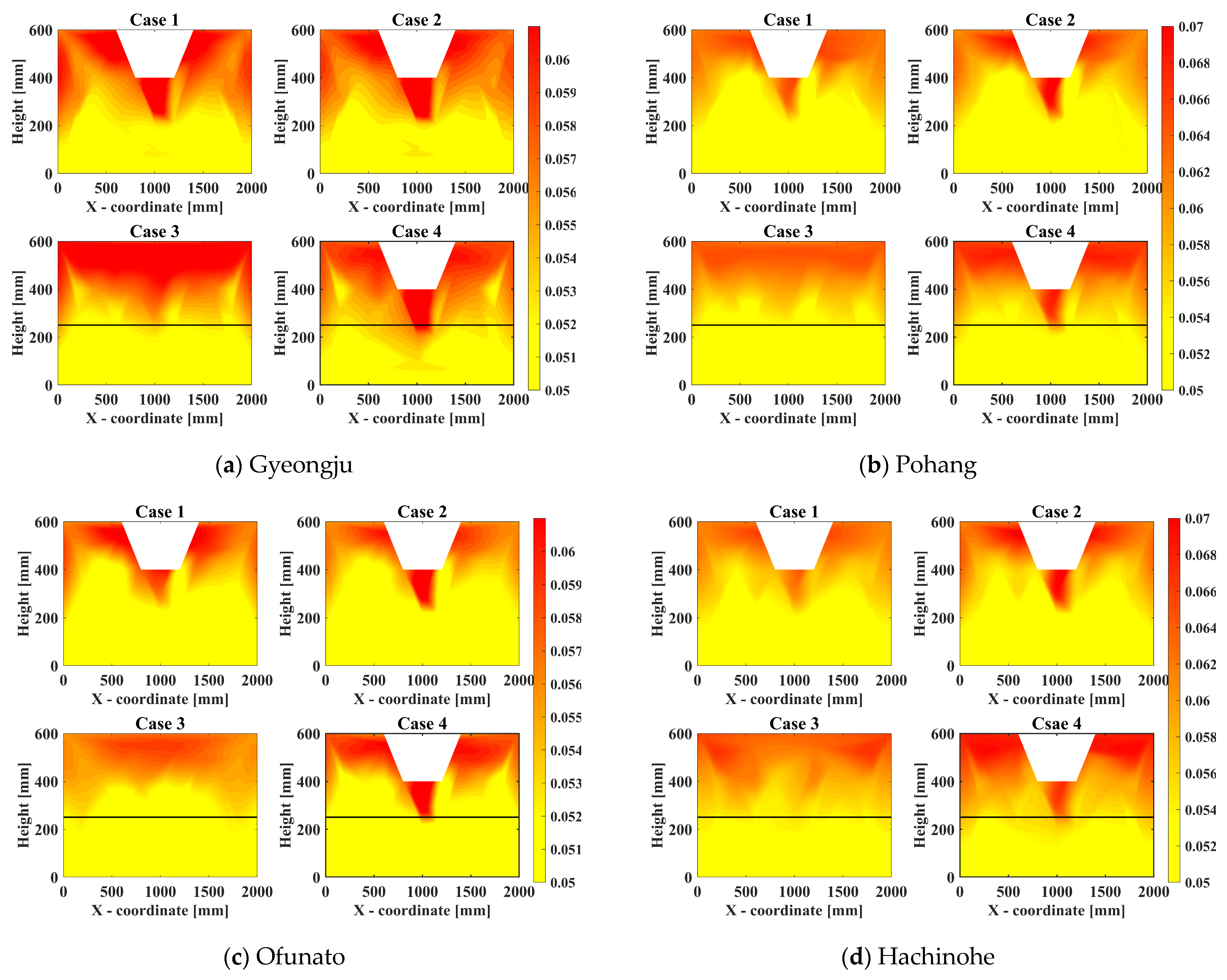
3.1.3. PGA Contours of the Model Ground

Figure 6 shows the PGA contours at the peak points of each seismic wave, illustrating the acceleration amplification trends in the ground models. The spacing between accelerometers was interpolated using the spline interpolation method. The overall trend of seismic wave propagation indicates that in all four ground models, high accelerations start from the lower part of the slope and increase towards the top. The PGA trend in Case 1 and Case 2 shows that the amplification is greater and more pronounced in Case 1, which is relatively less dense. For the multi-layered Cases 3 and 4, additional amplification was observed at the points where the layers change. By comparing the ground models, it was confirmed that the amplification of seismic waves in the ground is influenced by density and that the layered structure of the ground plays a significant role in seismic wave amplification. Additionally, as shown in Figure 6, the differences in acceleration at various points can significantly impact the design depending on the acceleration at the specific points used.
Furthermore, the PGA contour plots helped identify the extent to which PGA influences the slope. The impact of PGA was analyzed for the crests (at points of 600 and 1400 mm) of the slope, revealing that the influence extended to 61.17–76.67% for the Gyeongju earthquake wave, 47.17–66.33% for the Ofunato wave, 56–70% for the Pohang wave, and 56.33–85% for the Hachinohe wave. In addition, the average PGA influence across the slope models was 65.08% for Case 1, 55.08% for Case 2, and 67% for Case 4. It was confirmed that the influence range of PGA was the smallest in the densest model ground, Case 2, indicating that the stability of the slope is higher in this dense model ground compared to the other two model grounds. Overall, the average PGA influence was measured to be approximately 62%.
Based on these observations, it can be inferred that the overall influence of PGA on the slope is likely around 60%. Therefore, when designing for seismic conditions, it may be prudent to consider that around 60% of the total PGA influence could be concentrated in the topmost portion of the slope, which should be factored into slope design for more reliable safety measures.

4. Comparative Analysis of 1 g Shaking Table Experiment Results and Numerical Simulation Results

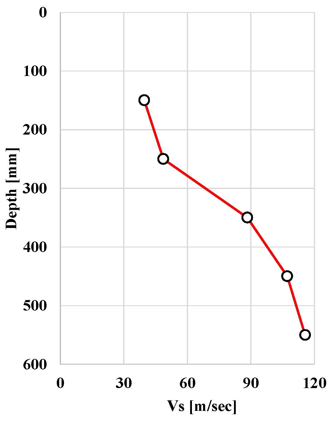
To verify the validity of the shaking table experiment results, a comparative analysis was conducted using two-dimensional finite element analysis. The numerical simulations were carried out using SIMULIA’s Abaqus Ver. 6.14 software, a finite element analysis program that supports a wide range of analyses from linear to nonlinear. The model was constructed to match the size of the physical experiment, with a total cross-sectional depth of 60 cm and a width of 200 cm, as shown in Figure 7. The shear wave velocity parameters were obtained by measuring the impact from a hammer test on vertically arranged accelerometers, using the peak-to-peak method to determine the shear wave velocities for each layer. The input seismic waves used for the numerical simulations were the acceleration data measured at the bedrock during the shaking table experiments. For numerical analysis, the Mohr-Coulomb model has been used as this model has been successfully used for the similar studies [12,13,14] for comparison of the experimental results in the 1 g shaking table test. The Mohr-Coulomb model is widely utilized as it effectively and simply describes the mechanisms of soil and rock. Although the Mohr-Coulomb model is an elasto-plastic model that can describe both elastic and plastic states, it was confirmed that no plastic zones developed during this numerical analysis. To simulate the behavior of the 1 g shaking table in Abaqus, the CINPE4 infinite element was used to set infinite boundary conditions at both ends of the numerical model.

4.1. Input Prameters Used in Numerical Analysis

Table 2 presents the input parameters used in the numerical analysis. Since the model ground was constructed with different properties in the upper and lower layers, different parameters were inputted for each layer during the simulation. For the upper layer ( D r = 75%), the parameters used were a mass density of 1833 kg/m3, a friction angle of 23°, a Young’s modulus of 17,160 kPa, and a cohesion of 0.3 kg/cm2. For the lower layer ( D r = 85%), the parameters were a mass density of 1916 kg/m3, a friction angle of 25°, a Young’s modulus of 24,218 kPa, and a cohesion of 0.21 kg/cm2. Additionally, as shown in Figure 8, shear wave velocity data for each layer were inputted by conducting hammer tests on accelerometers embedded at various depths in the model ground.

4.2. Spectral Acceleration(SA) Analysis

The numerical analysis data obtained using the Abaqus program were converted to Spectral Acceleration (SA) to see if they were appropriately depicted in the frequency domain, as shown in Figure 9. The data from three accelerometers (AS11–13), measured in the slope section (lower, middle, and upper parts), were compared to check the alignment in the frequency domain. The AS11–13 results are represented in black, red, and blue, respectively. The experimental results are depicted with solid lines, while the numerical analysis results are shown with dotted lines. The comparison results showed that the shaking table experiment data and the numerical analysis data matched well in the frequency domain. In the upper part of the slope, the experimental results generally showed higher SA. This is believed to be due to physical factors such as amplification due to the natural frequency of the model ground and the presence of cracks, which can cause some amplification, unlike numerical calculations. Case 1 showed an average difference of about 3.22%, Case 2 about 3.39%, Case 3 about 2.56%, and Case 4 about 2.24%. Overall, the results showed a difference of about 2.85%, confirming that the results were very similar. The good match between the numerical analysis and experimental results suggests that the seismic testing using the 1 g shaking table is validated.

5. Conclusions

This study examined the seismic amplification characteristics in slope sections using the model grounds with single-layer slopes (Dr = 75% (Case 1), Dr = 85% (Case 2)) and multi-layer flat (Case 3) and slope (Case 4) model grounds on a 1 g shaking table. The peak ground acceleration (PGA) in the slope and vertical sections was compared, and the areas with significant impact on PGA were analyzed using contour plots. The reliability of the experimental results obtained from the model grounds on the 1 g shaking table was validated by comparing them with numerical simulation results. The findings of the study are as follows:
  • The analysis of peak ground acceleration (PGA) results showed that the acceleration amplification from the lower to the middle and upper parts of the slope was greater in the sloped model grounds compared to the flat model ground. The least amplification occurred in the flat ground of Case 3, while greater amplification was observed in the order of Case 1, Case 4, and Case 2.
  • The contour plots of PGA trends revealed varying patterns of amplification at different points. It was found that, on average, approximately 60% of the PGA impact occurred at the topmost part of the slope, with specific amplifications of about 31.75% at the upper slope and 27.85% at the lower slope compared to the input motion. These results suggest that the influence of PGA varies across different points on the slope, and such variations should be carefully considered when designing seismic reinforcement. In the multi-layered model ground, different amplification patterns were observed at the layer transition points, indicating that the stratification of the ground significantly affects seismic wave amplification. This finding underscores the importance of accurately understanding the layered structure during the design process.
  • When comparing the experimental results with the numerical analysis results through Spectrum Acceleration (SA), differences of 3.22%, 3.39%, 2.56%, and 2.24% were observed for each case. Overall, there was approximately a 3% difference. The good agreement between the numerical analysis and the 1 g shaking table experiment results suggests that the experiments using the shaking table are valid.
  • This study identified differences in seismic wave amplification due to variations in relative density and layered soils. It also observed varying PGA values at different points. These findings suggest that in future ground design, especially for various geometric configurations, it is crucial to consider the effects of layered soil profiles, differences in relative density, and the diverse PGA values at different points. Based on the contour plot analysis, it is considered that approximately 60% of the PGA impact should be considered in seismic design, particularly at the topmost part of the slope.

Author Contributions

Writing—original draft preparation, S.J.; validation, M.M.; review, editing and supervision, D.K. All authors have read and agreed to the published version of the manuscript.

Funding

This research was funded by the National Research Foundation of Korea (NRF), NRF-2021R1I1A3044804.

Institutional Review Board Statement

Not applicable.

Informed Consent Statement

Not applicable.

Data Availability Statement

The original contributions presented in the study are included in the article, further inquiries can be directed to the corresponding author.

Conflicts of Interest

The authors declare no conflict of interest.

References

  1. Keefer, D.K. Investigating Landslides Caused by Earthquakes—A Historical Review. Surv. Geophys. 2002, 23, 473–510. [Google Scholar] [CrossRef]
  2. Lee, S.I.; Seo, J.I.; Kim, J.H.; Ryu, D.S.; Seo, J.P.; Kim, D.Y.; Lee, C.W. International Research Trend on Mountainous Sediment-related Disasters Induced by Earthquakes. J. Korean Soc. For. Sci. 2017, 106, 431–440. [Google Scholar]
  3. Seo, J.I.; Lee, S.I.; Kweon, H.K.; Chun, K.W.; Kim, S.W.; Jun, K.W.; Kim, J.H.; Lee, C.W. Future Research Direction in Response to Mountainous Sediment-Related Disasters Induced by Earthquakes in South Korea. Crisinomy 2018, 14, 119–138. [Google Scholar] [CrossRef]
  4. Park, S.; Kim, W.; Lee, J.; Beak, Y. Case Study on Slope Stability Changes Caused by Earthquakes—Focusing on Gyeongju 5.8 ML EQ. Sustainability 2018, 10, 3441. [Google Scholar] [CrossRef]
  5. Kim, S.-H.; Lee, K.-W. A Study on Stabilization of the Collapsed Slope due to Gyeongju Earthquake at Seokguram Access Road based on Geological Investigation. J. Korean Geosynth. Soc. 2019, 18, 225–242. [Google Scholar]
  6. Jibson, R.W. Summary of Research on the Effects of Topographic Amplification of Earthquake Shaking on Slope Stability; U.S. Geological Survey: Reston, VA, USA, 1987; pp. 1–166.
  7. Bard, P.Y.; Riepl-Thomas, J. Wave propagation in complex geological structures and their effects on strong ground motion. Wave Motion Earthq. Eng. 1999, 38–95. [Google Scholar]
  8. Paolucci, R. Amplication of earthquake ground motion by steep topographic irregularities. Earthq. Eng. Struct. Dyn. 2002, 31, 1831–1853. [Google Scholar] [CrossRef]
  9. Burjanek, J.; Fäh, D.; Pischiutta, M.; Rovelli, A.; Calderoni, G.; Bard, P.-Y. JRA1 Site Effects at Sites with Pronounced Topography: Overview & Recommendations; ETH: Zurich, Switzerland, 2014. [Google Scholar]
  10. Korean Geotechnical Society. Earthquake-Resistant Design of Ground Structures; Goomibook: Seoul, Republic of Korea, 2006; pp. 199–200. [Google Scholar]
  11. Lin, M.-L.; Wang, K.-L. Seismic slope behavior in a large-scale shaking table model test. Eng. Geol. 2006, 86, 118–133. [Google Scholar] [CrossRef]
  12. Kim, H.; Jin, Y.; Lee, Y.; Kim, H.S.; Kim, D. Dynamic Response Characteristics of Embankment Model for Various Slope Angles. J. Korean Geosynth. Soc. 2020, 19, 35–46. [Google Scholar] [CrossRef]
  13. Jin, Y.; Kim, H.; Kim, D.; Lee, Y.; Kim, H. Seismic Response of Flat Ground and Slope Models through 1 g Shaking Table Tests and Numerical Analysis. Appl. Sci. 2021, 11, 1875. [Google Scholar] [CrossRef]
  14. Jin, Y.; Jeong, S.; Kim, D. Prediction of Dynamic Behavior of Large-Scale Ground Using 1 g Shaking Table Test and Numerical Analysis. Material 2023, 16, 6093. [Google Scholar] [CrossRef] [PubMed]
  15. Zhou, Z.; Ren, C.; Xu, G.; Zhan, H.; Liu, T. Dynamic Failure Mode and Dynamic Response of High Slope Using Shaking Table Test. Shock Vib. 2019, 2019, 4802740. [Google Scholar] [CrossRef]
  16. Park, S.G. Behavioral Characteristics of Slope by Constrained Soil Nail Head Using 1-g Shaking Table Tests. Master’s Thesis, Chungbuk National University, Cheongju, Republic of Korea, 2012. [Google Scholar]
  17. Srilatha, N.; Madhavi Latha, G.; Puttappa, C.G. Effect of frequency on seismic response of reinforced soil slopes in shaking table tests. Geotext. Geomembr. 2013, 36, 27–32. [Google Scholar] [CrossRef]
  18. Hu, H.; Huang, Y.; Xiong, M.; Zhao, L. Investigation of seismic behavior of slope reinforced by anchored pile structures using shaking table tests. Soil Dyn. Earthq. Eng. 2021, 150, 106900. [Google Scholar] [CrossRef]
  19. Zhang, J.; Li, Y.; Zhang, C. Pounding induced overturning resistance of FPB-isolated structures considering soil-structure-interactions. Soil Dyn. Earthq. Eng. 2024, 177, 108416. [Google Scholar] [CrossRef]
  20. Liu, G.; Meng, H.; Song, G.; Bo, W.; Zhao, P.; Ning, B.; Xu, X. Numerical simulation of wedge failure of rock slopes using three-dimensional discontinuous deformation analysis. Environ. Earth Sci. 2024, 83, 310. [Google Scholar] [CrossRef]
  21. Du, W.; Wang, G. Fully probabilistic seismic displacement analysis of spatially distributed slopes using spatially correlated vector intensity measures. Earthq. Eng. Struct. Dyn. 2014, 43, 661–679. [Google Scholar] [CrossRef]
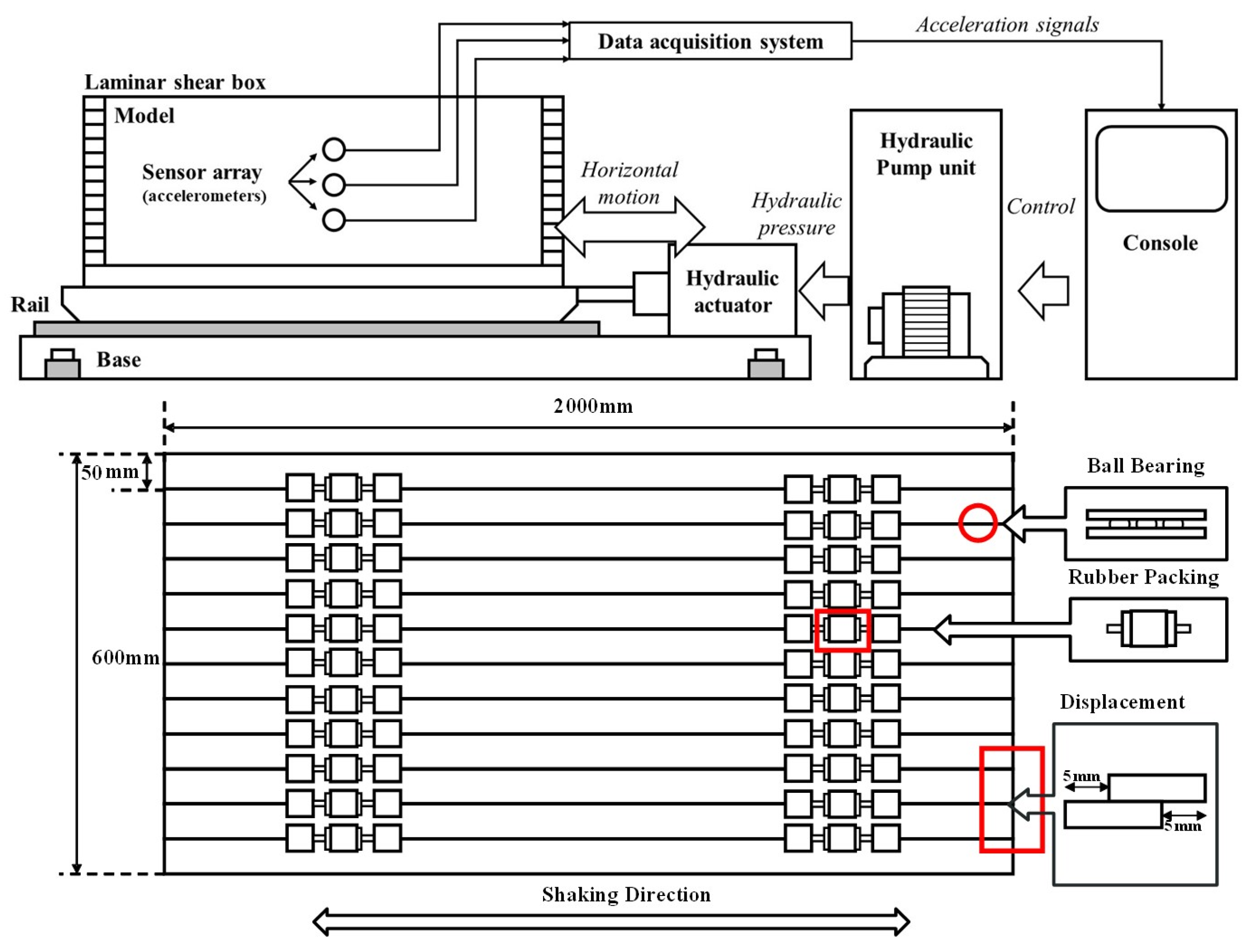
Figure 1. 1 g Shaking table and laminar shear box (LSB).
Applsci 14 09014 g001
Figure 2. Input—motion.
Applsci 14 09014 g002
Figure 3. Ground model (a) Case 1 D r = 75% ground model, (b) Case 2 D r = 85% ground model, (c) Case 3 2layer flat ground model, (d) Case 4 2layer slope ground model.
Applsci 14 09014 g003
Figure 4. Slope section PGA (AS11, AS12, AS13). (a) Gyeongju; (b) Pohang; (c) Ofunato; (d) Hachinohe; (e) Gyeongju PGA amplification factor; (f) Pohang PGA amplification factor; (g) Ofunato PGA amplification factor; (h) Hachinohe PGA amplification factor.
Applsci 14 09014 g004
Figure 5. Vertical section PGA. (a) Gyeongju; (b) Pohang; (c) Ofunato; (d) Hachinohe; (e) Gyeongju PGA amplification factor; (f) Pohang PGA amplification factor; (g) Ofunato PGA amplification factor; (h) Hachinohe PGA amplification factor.
Applsci 14 09014 g005aApplsci 14 09014 g005b
Figure 6. PGA contours for each seismic wave.
Applsci 14 09014 g006
Figure 7. Boundary settings: (a) Infinite boundary flat model in ABAQUS; (b) Infinite boundary slope model in ABAQUS.
Applsci 14 09014 g007
Figure 8. Shear wave velocity.
Applsci 14 09014 g008
Figure 9. Comparison of spectral acceleration results between numerical analysis and 1 g shaking table tests: (a) Case 1 ( D r = 75%) ground model, (b) Case 2 ( D r = 85%) ground model, (c) Case 3 (2layer flat) ground model, (d) Case 4 (2layer slope) ground model.
Applsci 14 09014 g009
Table 1. Physical Conditions of Test Specimens.
PropertyValuePropertyValue
Specific gravity
( G s )
2.65Mean particle size
( d 50 ) [mm]
0.235
Minimum void ratio ( e m i n )0.64coefficient of curvature ( C c )1.03
Maximum void ratio ( e m a x )1.06 coefficient of uniformity ( C u )1.76
Angle of internal friction ( ϕ ) [ ° ]38Unified soil classification system (USCS)SP
Table 2. Input parameters.
Relative Density 75% Ground Property Conditions
PropertiesValuePropertiesValue
Mass density [kg/m3]1833Young’s modulus [kPa]17,160
Friction Angle [°]23Cohesion [kg/cm2]0.32
Relative Density 85% Ground Property Conditions
PropertiesValuePropertiesValue
Mass density [kg/m3]1916Young’s modulus [kPa]24,418
Friction Angle [°]25Cohesion [kg/cm2]0.21
Disclaimer/Publisher’s Note: The statements, opinions and data contained in all publications are solely those of the individual author(s) and contributor(s) and not of MDPI and/or the editor(s). MDPI and/or the editor(s) disclaim responsibility for any injury to people or property resulting from any ideas, methods, instructions or products referred to in the content.