Article

High-Gain Multi-Band Koch Fractal FSS Antenna for Sub-6 GHz Applications

by
Atul Varshney
1,* and
Duygu Nazan Gençoğlan
2,*
1
ECE Department, FET, Gurukula Kangri (Deemed to Be University), Haridwar 249404, Uttarakhand, India
2
Department of Electrical-Electronics Engineering, Faculty of Engineering, Adana Alparslan Türkeş Science and Technology University, Adana 01250, Türkiye
*
Authors to whom correspondence should be addressed.
Appl. Sci. 2024, 14(19), 9022; https://doi.org/10.3390/app14199022 (registering DOI)
Submission received: 11 September 2024 / Revised: 27 September 2024 / Accepted: 30 September 2024 / Published: 6 October 2024
(This article belongs to the Special Issue Antenna Design and Microwave Engineering)

Abstract

:

Featured Application

The proposed antenna is potentially suitable for Wi-MAX (3.5 GHz) and sub-6 GHz n77 (3300–3800 MHz), n78 (3300–4200 MHz), and n79 (4400–4990 MHz), in addition to C-band applications.

Abstract

This study introduces a novel antenna based on the binary operation of a modified circular patch in conjunction with the Koch fractal. The antenna is intended for applications in the sub-6 GHz band, partial C-band, and X-band. The low-cost antenna is fabricated on a 1.6-mm-thick FR-4 substrate. A frequency-selective surface (FSS) is used to overcome the decreased values of the gain and bandwidth due to the fractal operations. The introduced split ring resonator (SRR) and the antenna substrate dimension reduction reduce the bandwidth and antenna gain. The air gap between the FSS and the antenna not only enhances the antenna gain but also controls the frequency tuning at the design frequency. The antenna size is miniaturized to 36.67%. A monopole antenna ground loaded with an SRR results in improved closest tuning (3.44 GHz) near the design frequency. The antenna achieves a peak gain of 9.37 dBi in this band. The FSS-based antenna results in a 4.65 dBi improvement in the gain value with the FSS. The measured and simulated plots exhibit an excellent match with each other in all three frequency bands at 2.96–4.72 GHz. These bands cover Wi-MAX (3.5 GHz), sub-6 GHz n77 (3300–3800 MHz), n78 (3300–4200 MHz), and approximately n79 (4400–4990 MHz), in addition to C-band applications.

1. Introduction

The ability of fractal antennas to accomplish downsizing while maintaining high performance characteristics has led to their widespread consideration in the field of antenna design [1,2,3,4,5,6,7]. Numerous studies have looked into small fractal antennas for use in communication systems [3,5,6], radar [8], wearable device applications [9,10,11,12], and other fields. In order to construct small antennas operating at various frequency bands, the application and use of fractal geometries such as the Minkowski fractal [8,12,13,14], Koch fractal [15,16,17,18], and other fractal structures [19,20,21,22,23,24] have been researched. The significance of miniature fractal antennas for communication applications is highlighted by research conducted by Froumsia et al. and Kaur and Sivia [25,26]. These investigations also support the use of fractal architectures to reduce the size without sacrificing functionality.
The idea of using fractal-based designs for dual-band and multi-band applications is supported by research by Yu et al. and Swetha and Naidu, which contributes to the adaptability of fractal antennas in contemporary communication systems [22,27]. Furthermore, the use of fractal antennas to achieve wide-band and tri-band operation is demonstrated in the papers by Suvarna et al. and Anguera et al. [21,28]. References [21,28] address the growing need for numerous frequency band applications, showcasing the promise of fractal architectures. Furthermore, the research conducted by Sharma and Bhatia offers a thorough examination of hybrid fractal antennas, including valuable perspectives on the antennas’ performance parameters and applications, as well as various fractal antenna configurations [29].
The literature survey shows a growing interest in miniaturized fractal antennas for wireless applications. Researchers are exploring different fractal geometries, feeding techniques, and structures to improve the antenna performance while reducing the size. Fractal antennas have unique properties like self-similarity and space filling, making them promising for future wireless communication systems. Fractal antennas offer a versatile platform for the design of miniaturized antennas with enhanced performance across various frequency bands. Dahiya et al. propose a multi-band high-gain slotted fractal antenna with circular and rectangular fractal structures for X-band and Ku-band applications, highlighting the potential of integrating different fractal shapes for successful multi-band applications [30]. Jayarenjini introduces a CPW-fed hexagonal ring fractal antenna with a labyrinth resonator, demonstrating its use for omnidirectional wireless applications [31]. Shookooh et al. explore the use of Koch, Sierpinski, and Minkowski shapes for ultra-wide-band metamaterial microstrip array antennas due to their self-similarity features [32]. Kodali et al. developed an arrow cross-shaped slotted fractal antenna with an enhanced bandwidth for Wi-Fi, WiMAX, and WLAN applications, catering to the growing demand for high-speed wireless communication systems [33]. Meanwhile, Kattimani and Patil optimized a Vicsek snowflake-box fractal microstrip patch antenna using a defective ground structure, demonstrating the effectiveness of fractal unit cells for miniaturization and improved bandwidths [34]. Kumar and Jayappa suggest a Sierpinski carpet fractal monopole antenna for ultra-wide-band applications. The proposed fractal antenna is intended to achieve multiple bandwidth applications [35].
The literature shows various applications and advantages of using different fractal geometries in antenna design, including multi-band operation, enhanced bandwidths, and miniaturization. However, challenges remain, especially for 5G sub-6 GHz applications. Varshney et al. presented an outer appended tri-arm rectangular arm circular antenna with an SRR triplet, improving the gain (7.16 dBi) and bandwidth without an FSS [36]. Varshney et al. also developed a compact, arrowhead-shaped miniaturized antenna for the Wi-MAX and n78 bands, despite its limited bandwidth and low gain value of 2.47 dBi [37]. Singh et al. have developed a compact offset edge-fed odd-symmetric double-mixed Koch–Minkowski fractal slotted antenna with a gain of 4.72 dBi, suitable for UWB applications [38]. Furthermore, Varshney et al. showed that the notch band may be eliminated from the passband by utilizing complementary SRR. This would produce an outer extended circular fractal antenna with a low gain value and a broad bandwidth of 1.63 to 2.91 GHz [39]. Kushwaha and Kumar designed a CPW-fed high-gain circularly polarized L-slotted antenna at 3.5 GHz. The FSS size and gap are much larger, which increases the overall volume of the antenna. This antenna results in a 3–4 dBi enhancement in the gain with an FSS [40]. Devarapalli et al. developed a CPW-fed tree-shaped fractal elliptical antenna for dual-band applications, achieving bandwidths of 2.49–4.36 GHz and 7.96–9.92 GHz with peak gains of 2.84 and 6.15 dBi, respectively, and a gain of 9.34 dBi [41]. Chen and Tao have developed a dual-band FSS U-slotted patch antenna to enhance the bandwidths, gains, and reflection coefficients for 2.45 GHz and 5.8 GHz Bluetooth and WLAN applications [42]. Sah et al. have demonstrated a dual-band slotted antenna in which gain enhancement is achieved using a dual-band 7 × 7 novel FSS. The FSS is used as a superstrate that achieves dual bands of 3.48–3.65 GHz and 5.75–6.37 GHz with gains of 13 and 13.92 dBi [43]. Peddakrishna and Khan’s study on slotted elliptical patch FSS antennas at 5.38 GHz revealed a 2.5 dBi gain improvement from the FSS superstrate at 28.5 mm from the radiator [44]. Zhu et al. have developed a dual-polarized antenna for 5G wireless local networks, featuring two orthogonal bow-tie dipoles and a ground plane and wide band (4–6.5 GHz) with a ring slot connecting rectangular slots, resulting in a 40% bandwidth improvement and 5.6 dBi gain improvement [45]. Bouslama et al. have developed a high-gain resonant cavity antenna with an FSS superstrate at 6 GHz to enhance its radiation characteristics [46].
The literature survey reveals the following research gaps.
  • First, traditional antenna designs struggle to achieve significant miniaturization without compromising key performance metrics such as the gain, bandwidth, and reflection coefficients. This study employs fractal geometries, specifically Koch curves, to achieve a substantial size reduction while maintaining and even enhancing the performance parameters.
  • Effective frequency tuning techniques are lacking in many current antenna designs, but this is crucial for flexible and adaptable 5G applications. This research presents a strong method for frequency tunability by incorporating frequency-selective surfaces (FSS), allowing the antenna to function effectively across many frequency bands. The literature [41,43,46,47,48,49] makes it clear that the FSS size can be maintained at the same level as the antenna. However, there are instances where the FSS size is greater than the antenna size [40,42,50,51]. The antenna’s cost increases with the size, since a larger antenna requires more substrate.
  • It is still very difficult to achieve both a large bandwidth and high gain at the same time, especially in smaller antennas. An improved bandwidth and gain are obtained over the intended frequency ranges by means of the suggested design, which optimizes the fractal geometry’s dimensions and its iterative processes for FSS integration. Although SRRs have been proven to improve the antenna properties, the present designs frequently fail to fully leverage their potential. This study shows how SRRs can be used to improve the gain and tunability even in small designs by including SRR loading with reduced ground planes.
  • The resonance frequency tuning of most antennas in the literature is not adjusted with the design frequency.
  • The antenna’s overall volume is increased by the air gap between the substrates.
This research presents a comprehensive optimization process for antenna design for 5G sub-6 GHz applications, focusing on multiple performance metrics. The innovative combination of fractal geometries and FSSs, SRRs, and comprehensive optimization sets a new standard for miniaturized, tunable, and high-performance antennas. The proposed FSS-based miniaturized fractal antenna demonstrates significant advancements in terms of size reduction, tunability, and performance enhancement, making it a promising solution for next-generation 5G applications. The research design is innovative, as the FSS is designed to be smaller than the main antenna size, making the antennas economically feasible. This research provides a comprehensive approach to antenna design, addressing the current limitations and setting a new benchmark in RF communication applications. The overall volume of the antenna is reduced by maintaining a lower air gap. This research contributes to tunability of the resonating frequency at the designed frequency by reducing the air gaps, while maintaining the antenna gain by balancing the tunability and gain enhancement conditions. The design complexity is reduced by designing the simplest FSS design structure and reducing the FSS size to be lower than the antenna size. This antenna is applicable not only for the sub-6 GHz band but also for C-band applications.
This work is structured as follows. Section 2 explains the design’s development. Section 3 outlines the parametric investigation and the measured and simulated results’ analysis. Finally, the work is concluded in Section 4 by highlighting the antenna’s limitations, applications, and future scope.

2. Materials and Methods

2.1. Principle of Koch Fractal

The Koch fractal is a geometric pattern that begins with an equilateral triangle, removes the inner third of each side, builds another equilateral triangle at the removed side, and repeats this process indefinitely, although these rules may vary in the literature [38]. In the first iteration, an equilateral triangle is added to the line length ( l ), with its base being one-third of the iteration 0 line. This process is repeated in the next iteration, increasing the baseline’s length by one-third. The basic Koch fractal principle is illustrated in Figure 1. The following formulas are used for the Koch fractal iterations.
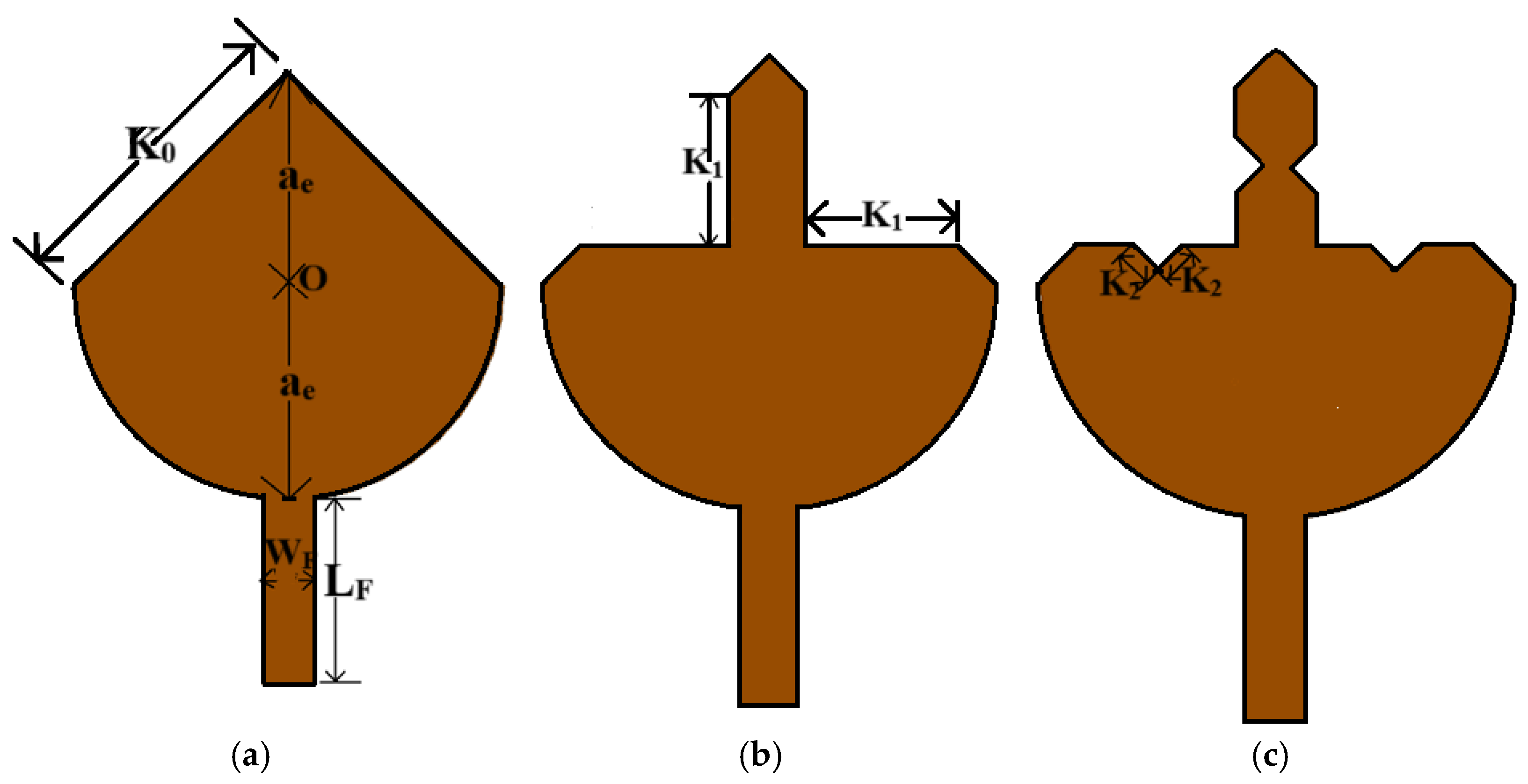
K 0 = l
K 1 = l 3
K 2 = l 3 3 K 2 = l 9

2.2. Koch Fractal Antenna Patch Development

The proposed Koch semi-circular patch has evolved through the novel concept of the binary addition of a circular patch (evaluated at a design frequency of 3.5 GHz) and a Koch fractal with two iterations. The effective radius of the circular patch (ae) is evaluated as 11.98 mm using Equations (4)–(7) [36,52].
Circular patch antenna radius:
a e = F 1 + 2 h π ε r F ln π F 2 h + 1.7726 1 2
where h is given in cm, and
F = 8.791 × 10 9 f r ε r
Feed width:
W F = 7.48 h e Z 0 ε r + 1 87
Initial substrate dimensions:
WS × LS = 4ae × 4ae
The binary operation of the circular patch is used to develop the iteration-0 Koch operation, as illustrated in Figure 2. The development of the two-stage Koch fractal and the patch of the proposed antenna are represented in Figure 3a–c. The basic concept of the Koch fractal, as explained in Section 2.1, has been applied to develop the shape of the antenna patch. In iteration 0, the Koch length is 16.94 mm, i.e., K/2N, where N = 0 and 2 is the Koch fractal factor (chosen instead of 3, as mentioned in Section 2.1). The length of the iteration-0 line is equal to the side length of the circle of radius 11.98 mm with four segments. The K0 is measured at 16.94 mm, as displayed in Figure 3a. In iteration 1, the length of the Koch triangle’s base cut is evaluated using K1 = K0/2, i.e., half of the total length of iteration 0–8.47 mm. A circle with four-line segments of this diameter (8.47 mm) is subtracted from iteration 0. It generates the iteration-1 patch, as displayed in Figure 3b. In iteration 2, the same process is repeated. In this step, the diameter of the Koch fractal is kept at just half of that of iteration 1 with four-line segments, and it is subtracted from iteration 1. This gives rise to the novel proposed patch shape, as displayed in Figure 3c.

2.3. Frequency-Selective Surface (FSS) Structure

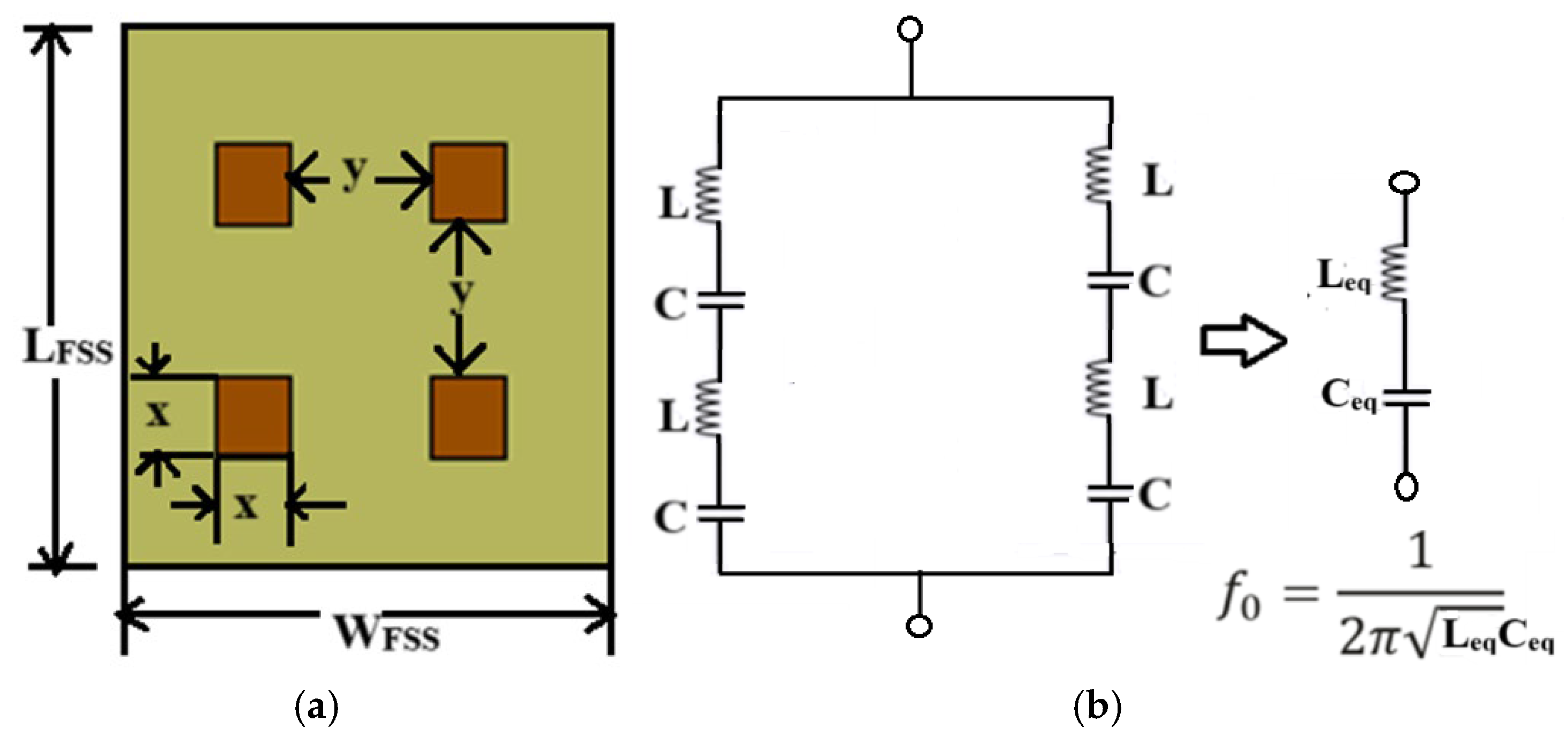
The frequency-selective surface (FSS) structure is developed on an FR-4 substrate to improve the gain and bandwidth of the proposed antenna at a frequency of 3.5 GHz. The FSS is developed to resonate at 3.5 GHz. To achieve this, four 5 mm × 5 mm square copper metal stubs, situated at a distance of 10 mm from each other, are etched on a single-layer FR-4 printed circuit board (PCB). It will behave as an LC resonating circuit that is tuned at 3.5 GHz. In this FSS structure, every square section behaves as an LC circuit. The total size of the FSS layer is 35.94 mm × 33.96 mm × 1.6 mm. The width of the FSS is exactly equal to the width of the antenna, i.e., 35.94 mm, while the length of the FSS is 33.96 mm, i.e., 5.01 mm (38.97 mm–33.96 mm) less than the length of the main antenna substrate. The final FSS structure is shown in Figure 4a. Every square copper stub of 5 mm × 5 mm will behave as an inductor, while the 10 mm separation between two stubs gives the value of the capacitor. Therefore, the electrical equivalent of the FSS is equal to the parallel combination of the two series combinations of two L and C circuits, as shown in Figure 4b. The overall circuit will behave as a single-tuned series LC circuit [53].

2.4. Fractal Antenna: Step-by-Step Design Development

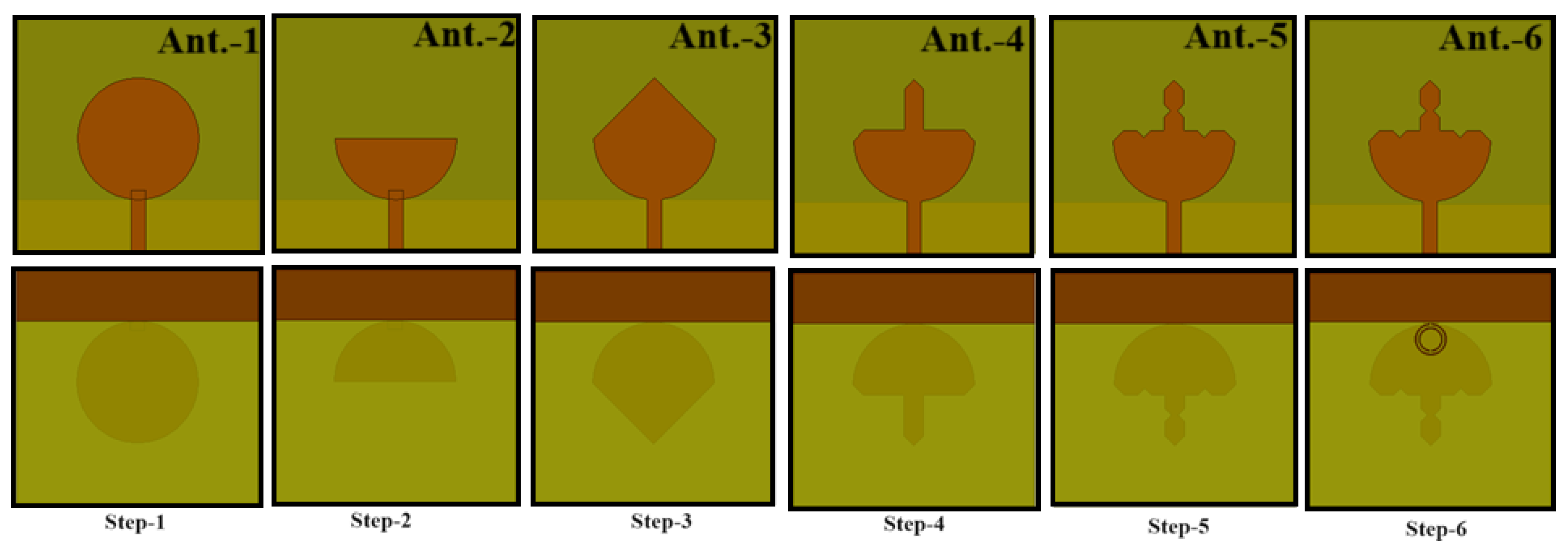
The monopole Koch fractal antenna’s step-by-step development is shown in Figure 5. The design begins with an evaluation of a circular patch on an FR-4 substrate of size 4ae × 4ae, where ae is the effective radius of the circular patch evaluated at a frequency of 3.5 GHz [36]. Then, in step 2, a semi-circular patch is removed from step 1, and another circle with a four-line segment (rhombus shape is attached at the same center of the circular patch), and binary addition is used to add the two sections, as displayed in step 3. In steps 4 and 5, Koch iteration-1 and iteration-2 fractals are created. Throughout these steps, the ground length is kept equal to a quarter of the guided wavelength, i.e., 10.21 mm (9.7 mm optimized value). In step 6, an SRR is designed at a frequency of 3.5 GHz and introduced near the monopole antenna ground at the bottom surface. This helps to enhance the bandwidth of the overall antenna.

2.5. Koch Fractal Antenna with Tunable FSS

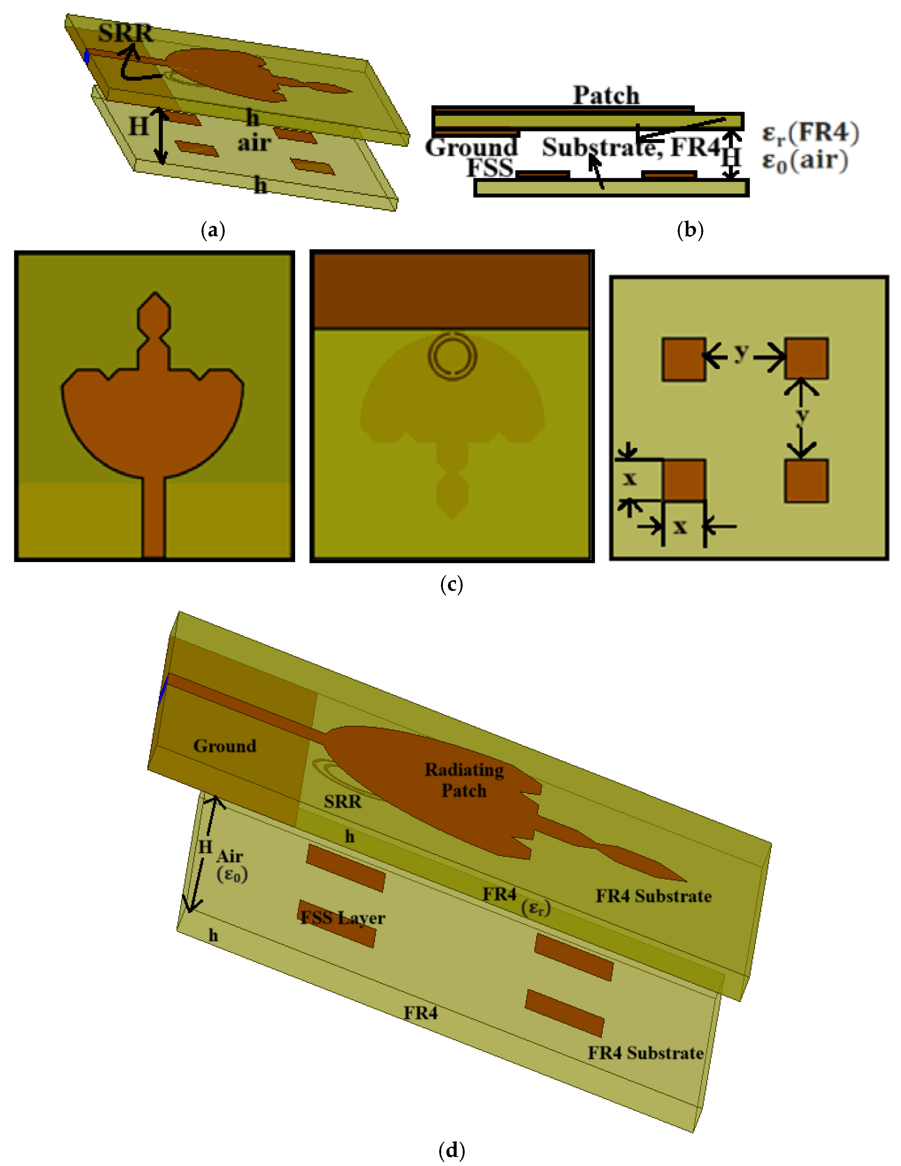
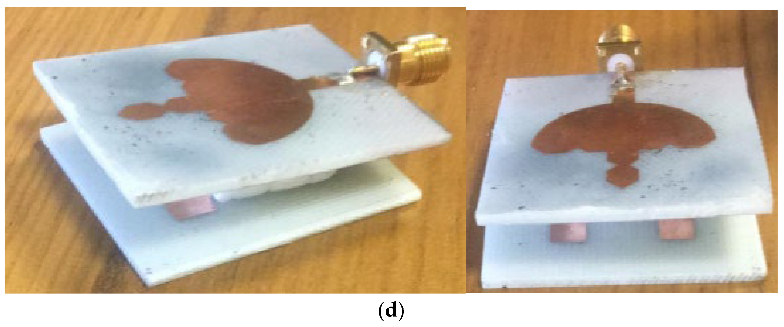
Initially, for tuning purposes, an FSS is introduced below the radiating patch at a height of 9.4 mm from the antenna radiator, as shown in Figure 6a. The distance between the two substrates (H) is kept equal to 7.8 mm, as displayed in Figure 6b. Both substrates of the patch and FSS are FR-4 with a thickness of 1.6 mm. After this, the FSS is varied from bottom to top at a 2.2 mm distance below the ground of the antenna in a step size of 0.8 mm. It is found that the antenna is tuned at a frequency of 3.5 GHz with a 3.8 mm air gap between the substrates, while an improved gain is obtained at an air gap of 7.0 mm (proposed design). The designed FSS is simple and contains only four square copper stubs with a side length of 5 mm and separated from each other by 10 mm. The top layer, bottom layer, and FSS surface views of the antenna are shown in Figure 6c. It is also noticed that the FSS below the antenna radiator improves the gain to a greater extent as compared to the FSS above the antenna radiator. The proposed antenna design model is represented in Figure 6d. All dimensions of the proposed antenna are illustrated in Table 1.
The variation in the distance between the patch and FSS surface changes the volume of air between the surfaces. Therefore, the cumulative effective dielectric constant changes to a new value and is given by [37]
ε r _ c u _ e f f e c t i v e = ε r e f f × h ( a n t e n n a ) + ε 0 ( a i r ) × H ( G a p ) h a n t e n n a + H ( G a p )
Cumulative effective wavelength:
λ r _ c u _ e f f e c t i v e = λ 0 ε r _ c u _ e f f e c t i v e
p h a s e d i f f . = F S S + 2 β d
where β is the propagation constant and d is the distance between the radiating patch and the surface of the FSS. Constructive interference will result when the p h a s e d i f f . is equal to either 0° or 2π.
Distance between antenna radiator and FSS layer:
d = 2 N π F S S 2 β = 2 N π F S S 2 ( 2 π λ r _ c u _ e f f e c t i v e )
where N = 0, 1, 2, 3, …
d = h ( s u b s t r a t e ) + H ( g a p )
Therefore, the gap between the substrates is
H g a p = d h

2.6. SRR Design at 3.5 GHz

The designed SRR with its LC equivalent at 3.5 GHz is represented in Figure 7. Its dimensions are indicated in Table 1. The LC resonating equivalent circuit of this SRR is precisely tuned at 3.50 GHz, with inductance L = 13.4987 nH and capacitance C = 153.043 fF.

3. Results and Discussion

This section presents the detailed parametric analysis of the fractals, SRR loading and reduced ground, FSS gap variations, miniaturization of the antenna, antenna prototype, reflection coefficients, radiation patterns, and gain validation. It also explains the current density distribution of the antenna at the resonating frequency and compares the proposed antenna with similar, recently published antennas.

3.1. Parametric Investigations

3.1.1. Effect of Fractals without Miniaturization

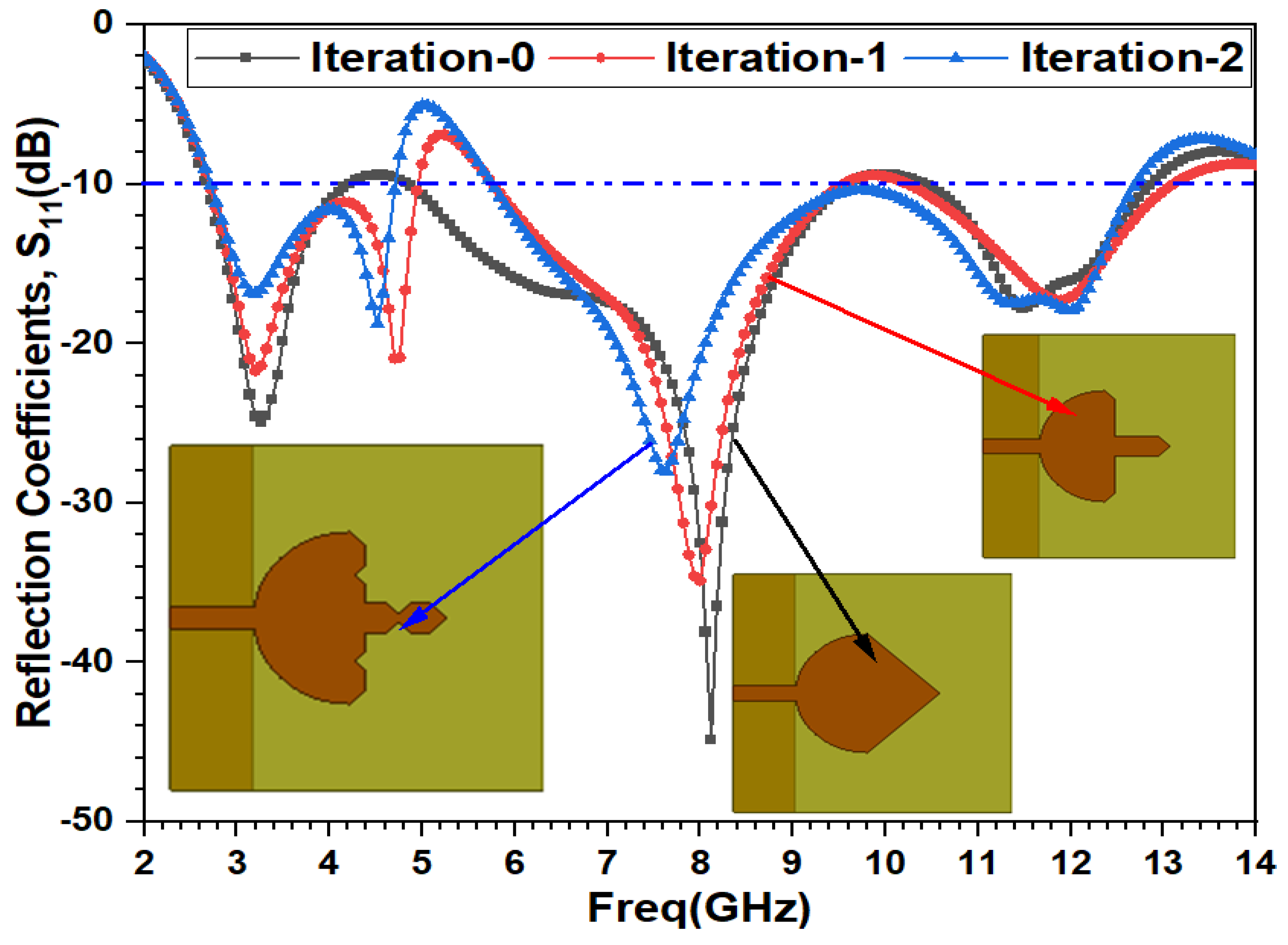
The reflection coefficient plots of three fractal operations on the modified circular patch monopole antenna (with substrate size = 47.92 × 46.15 mm2 without miniaturization) are compared in Figure 8. The modified circular (semi-circular triangle) patch results in a tri-band reflection coefficient curve. The lower band of iteration 0 covers the n77 and n78 5G sub-6 GHz bands. Additionally, it also covers the C-band and X-band. When iteration 1 is applied in this antenna, it results in a 4.01 dBi improvement in the gain value, at the cost of a reduction in the reflection coefficient value. Iteration 1 also adds an additional tuning frequency in the lower band at 4.70 GHz. Further fractal iteration (iteration 2) results in dual-band performance with a 0.57 dBi decrease in gain in comparison to iteration 1 at a frequency of 3.5 GHz. On the other hand, it widens the second mid-band below −10 dB at reflection coefficients from 5.75 to 12.70 GHz. All of the fractal parametric variation effects are showcased in Table 2.

3.1.2. SRR Loading with Reduced Ground

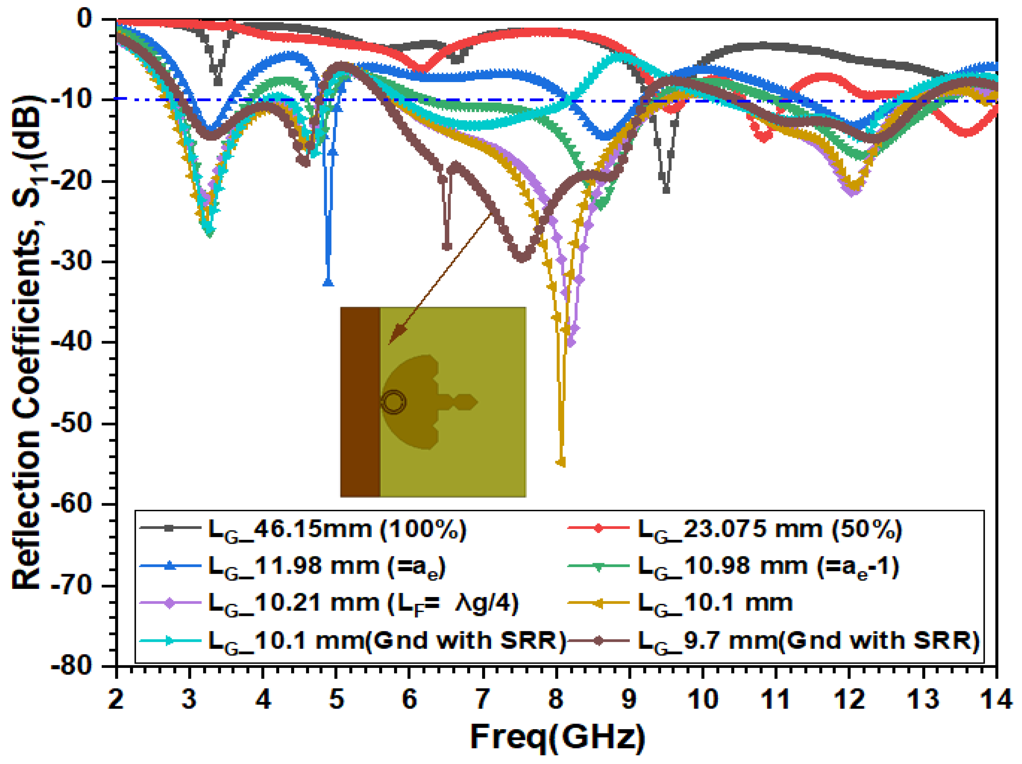
Initially, the designed parent antenna (substrate size = 47.92 × 46.15 mm2) with the full bottom surface ground and with 50% ground without an FSS yield no beneficial results below −10 dB. After this, the antenna ground length was reduced to a value equal to the radius of the fundamental circular patch, i.e., 11.98 mm. This would yield quad-narrow bands below −10 dB. The antenna achieves a gain value equal to 5.05 dBi at 3.5 GHz and a peak gain of 14.24 dBi at a resonating frequency of 10.82 GHz. The reduced ground length of 10.98 mm (ae − 1) results in quad-bands with a lower reflection coefficient, but it will yield an excellent peak gain of 12.36 dBi at the design frequency of 3.5 GHz and achieves a peak gain of 12.89 dBi at 3.26 GHz. Further, the ground length is reduced to a quarter guided wavelength (10.21 mm). This will achieve a lower resonance frequency at 3.26 GHz, much closer to the design frequency of 3.5 GHz. This also results in tri-wide bands. The lower band covers the main n77, n78, and partial n79 bands of the 5G sub-6 GHz range. This improves the fractional bandwidth and achieves a peak gain of 13.58 dBi at the lowest first band frequency of 3.20 GHz. Further, the length of the antenna is reduced to 10.1 mm. This will yield an improved bandwidth in the lower and upper bands and achieve a slightly reduced peak gain at a frequency of 3.20 GHz. A split ring resonator (SRR) designed at 3.5 GHz is placed at the bottom ground near the monopole ground with a length of 10.1 mm. This results in degraded values in the gain, as well as in the bandwidth. The only benefit of introducing an SRR is that it shifts the fixed resonating frequency towards 3.5 GHz and results in a resonating frequency tuned at 3.26 GHz and a gain reduced to 10.08 dBi at 3.5 GHz. The gain is further improved by reducing the ground length to 9.7 mm, without disturbing the position of the SRR. The gain is significantly improved to 15.11 dBi at 3.5 GHz, while the peak value of the gain of 16.66 dBi is achieved at 3.26 GHz. This also helps to improve the reduced value of the bandwidth in all tri-bands. The ground length reduction, parametric analysis, and reflection coefficients are shown in Figure 9, and the antenna parameters for each case are recorded in Table 3.

3.1.3. Antenna Miniaturization

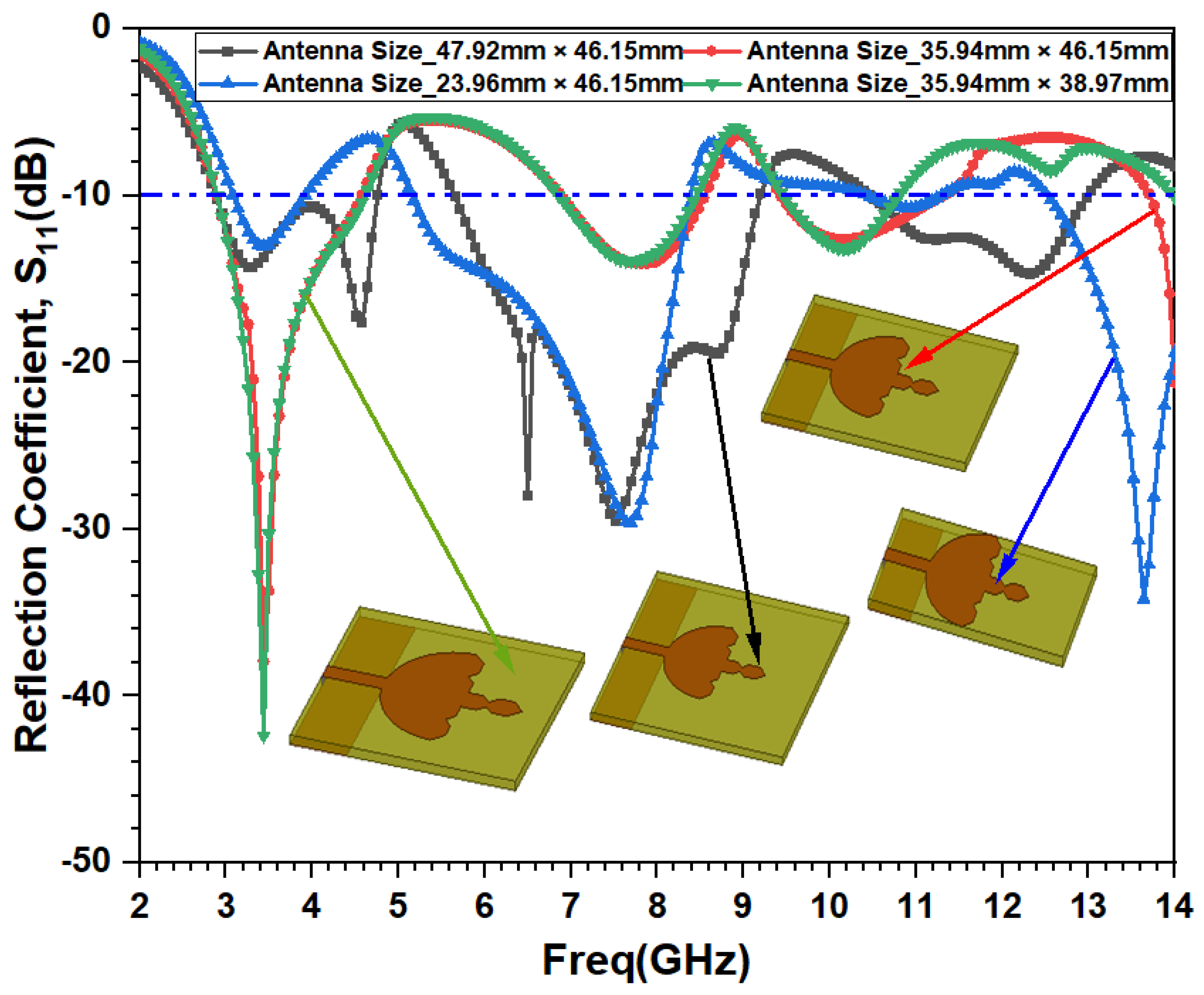
The primary substrate size of the designed antenna was equal to 47.92 mm × 46.15 mm {WS × LS = 4ae × (LF + 3ae)}. In this case, the antenna achieves a gain of 15.11 dBi at 3.5 GHz with tri-band performance. The antenna results in a wide sub-6 GHz bandwidth that covers the n77, n78, and partial n79 bands. After this, the ground width is reduced to three times the effective radius of the patch, i.e., 3ae = 35.94 mm. This ground size reduces the antenna size to 35.94 mm × 46.15 mm. This size miniaturization gives rise to an improvement in the antenna gain to 4.82 dBi, but it results in a decreased antenna bandwidth in the first band and tunes the antenna at 3.44 GHz, i.e., closest to the design frequency of 3.5 GHz. Further, the antenna width is reduced to 2ae = 23.96 mm, without beneficial results in favor of the sub-6 GHz FR-1 frequency band and covering only the n78 band. Therefore, the antenna width is selected as 3ae, and further reduction is carried out on the antenna substrate length, which is equal to LF + 2ae + 3h = 38.97 mm. This miniaturization results in the proposed antenna with an overall 36.67% degree of miniaturization in the substrate requirement for antenna fabrication as compared to the conventional circular antenna’s size (4ae × 4ae = 47.92 mm × 47.92 mm). This reduction in the antenna’s width and length will result in the first resonating frequency at 3.44 GHz, with an improved lower band bandwidth and a reduction in gain to 9.37 dBi. All reflection coefficients of the miniaturization process are shown in Figure 10, and their performance parameters are provided in Table 4. Therefore, it is required to improve the reduced values of the gain and bandwidth due to the miniaturization process by introducing a frequency-selective surface below the main antenna radiator.

3.1.4. FSS Loading for Frequency Tunability and Gain Enhancement

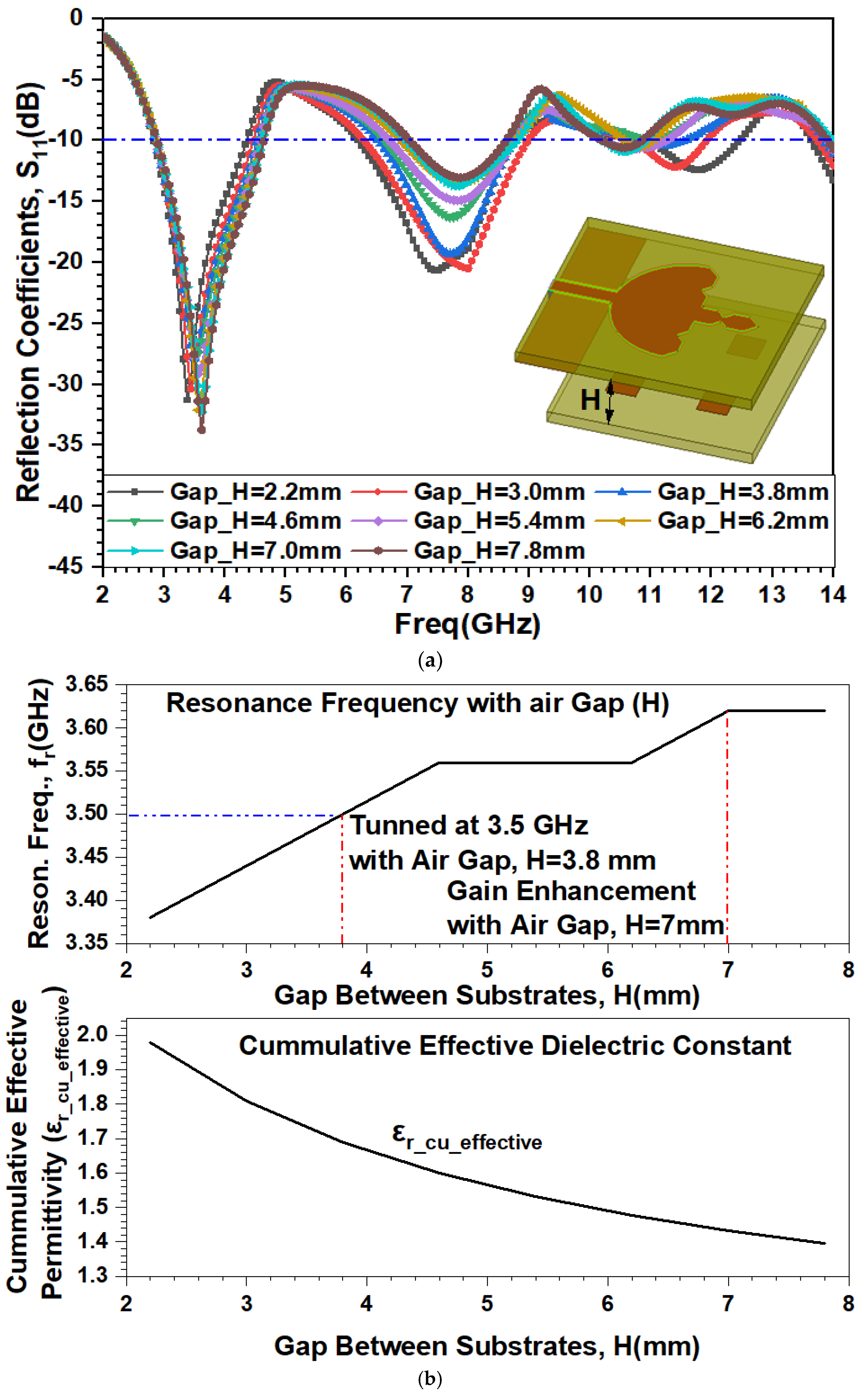
In the previous section, it is found that a miniaturized antenna results in a resonant frequency at 3.44 GHz, a reduction in the gain, and a −10 dB fractional bandwidth for the sub-6 GHz band. To achieve an appropriate resonant frequency at 3.5 GHz, an improvement in gain, and an enhancement in the first band −10 dB bandwidth, the miniaturized antenna is further loaded with an FSS structure, as discussed in Section 2.3. The distance between the two substrates (H) is varied at a step size of 0.8 mm below the antenna substrate. All of the reflection coefficients of the FSS loading and gain enhancement processes are shown in Figure 11a, and their performance parameters are given in Table 5. It is noticed from the table and figure that the exact resonance at 3.50 GHz occurs for an FSS gap 3.8 mm below the radiating patch antenna. It improves the tri-band bandwidth while reducing the gain to 7.14 dBi, and the first band bandwidth reduces from (2.90–4.61 GHz) to (2.86–4.53 GHz). As the air gap between the substrates increases, the lower band becomes stronger, with a right shift in the resonating frequency noticed, and the reflection coefficient values in the mid- and upper frequency bands become inferior. Since the first band bandwidth is almost the same in all cases, an excellent gain enhancement from 9.37 dBi (without FSS) to 14.02 dBi (with FSS) is achieved when the FSS is arranged at 7.0 mm beneath the ground of the antenna. Therefore, a 7.0 mm air gap below the FSS surface is considered the final case for the proposed design. The effect of the air gap will change the cumulative effective permittivity of the FSS antenna as given in Equation (4). The linear effect of the change in the resonating frequency and the cumulative effective permittivity of the FSS with the air gap is shown in Figure 11b. It is noticed that a 3.8 mm air gap is suitable for fine tuning, while an air gap from 4.6 to 6.4 mm does not change the resonating frequency, and an excellent gain enhancement in the miniaturized antenna is achieved with a 7.0 mm gap between the substrates.

3.1.5. Proposed Antenna with SRR Loading

The effect of the SRR loading effect on the miniaturized circular Koch fractal antenna is represented in Figure 12 in terms of their reflection coefficient curve comparisons, and these cases are showcased in Table 6. The miniaturized antenna, when loaded with an SRR, results in a reduced gain value from 13.38 dBi to 9.37 dBi. The advantage of loading the SRR is that it significantly improves the reflection coefficient below −10 dB and converts the single wide band (without SRR) into two narrow bands; this will help to reduce the application interference. The decreased value of the gain is maintained by placing an FSS layer beneath the antenna ground at a 7.0 mm distance. This helps to improve the bandwidth in the first two bands and enhances the gain from 9.37 dBi to 14.02 dBi at the design frequency.

3.2. Antenna Prototype Model

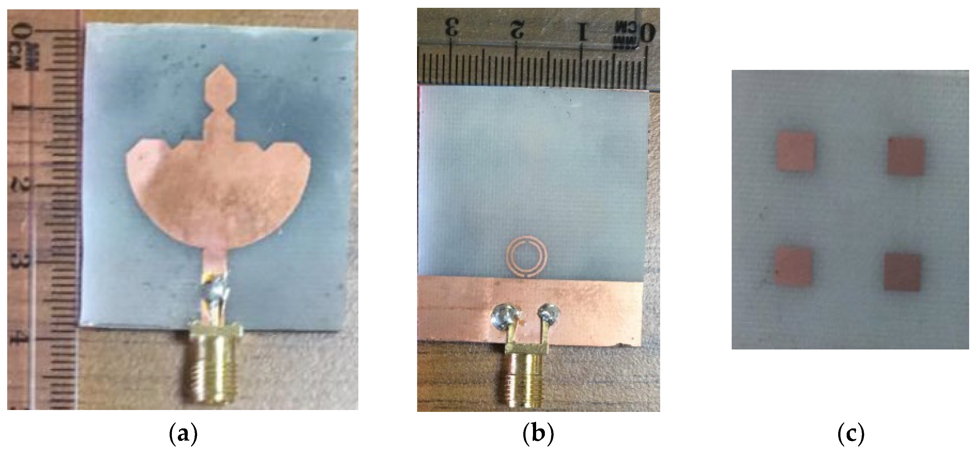
The top and bottom views of the fabricated miniaturized Koch fractal antenna are represented in Figure 13a,b. The FSS is fabricated on a 35.94 mm × 33.96 mm FR-4 substrate, as shown in Figure 13c. The antenna is placed above a 7.0 mm air gap by using foam pieces as separators, as shown in Figure 13d.

3.3. Simulated and Measured Reflection Coefficients

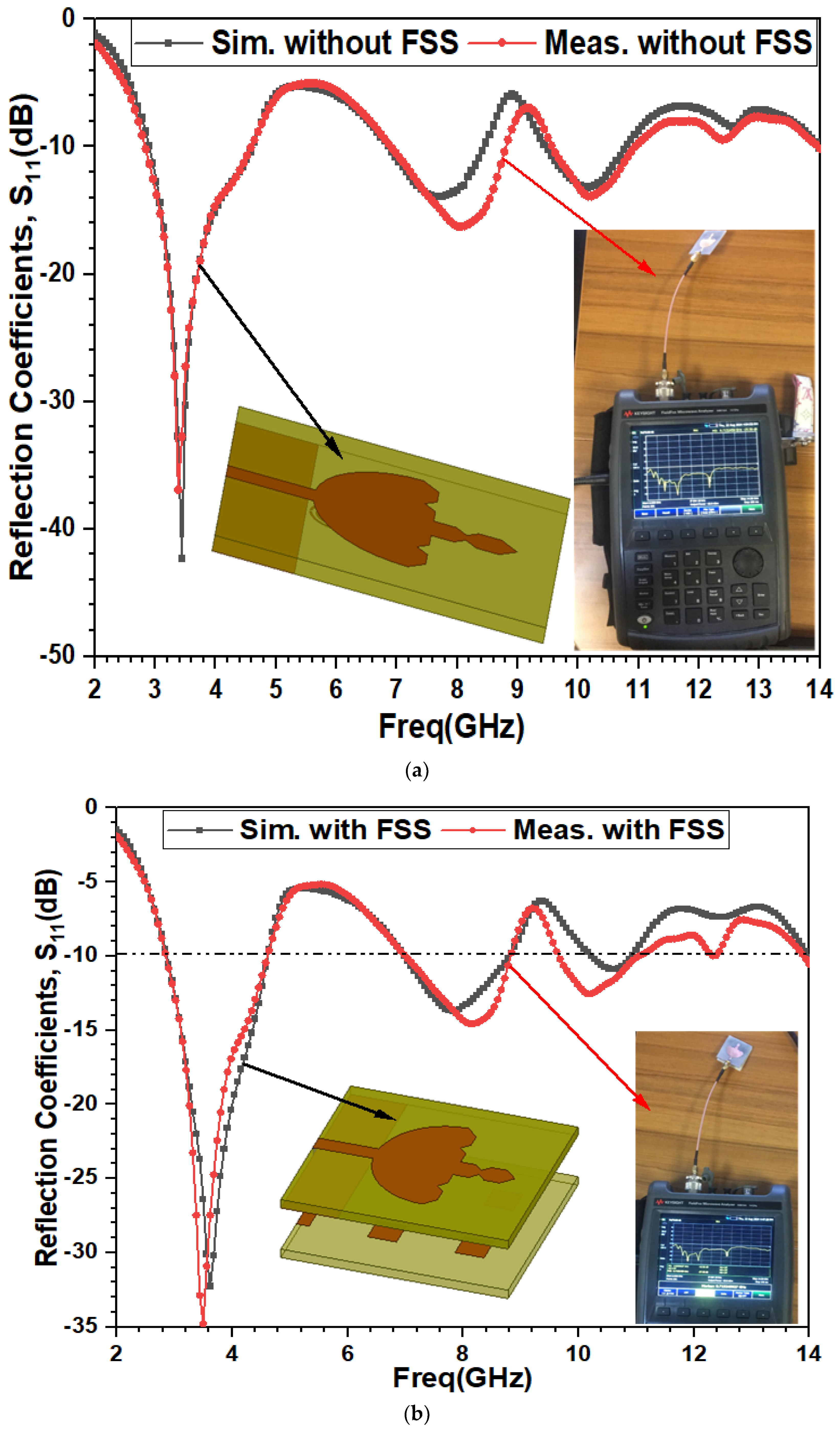
The reflection coefficients of the simulated and measured proposed circular Koch fractal antenna design without the FSS and with the FSS are compared in Figure 14a,b. The proposed antenna’s reflection coefficients are measured using the Keysight vector network analyzer (N9916A) separately. The measurement is conducted for a frequency sweep of 2 GHz to 14 GHz. They are found to be in excellent agreement in the lowest band, while some bandwidth variations are noticed in the middle and upper bands. In the lowest band, without the FSS, the resonance is measured at 3.38 GHz with a measured bandwidth of 2.90 GHz to 4.62 GHz, while, in the lowest band, with the FSS, the resonance is measured at 3.50 GHz with a measured bandwidth of 2.83 GHz to 4.64 GHz. These bandwidths are sufficient to cover the three most important bands (n77, n78, and partial n79) of the sub-6 GHz FR-1 range. In the second band, the variations in the measured bandwidth and the resonance frequencies are obvious because the antenna was fabricated on a low-cost FR-4 substrate that is suitable for a frequency range of up to 6 GHz. Meanwhile, above 6 GHz, it will show dispersion loss and frequency nonlinearity effects in its relative permittivity and loss tangents. Therefore, the overall losses of these materials increase above 6 GHz, and this will cause errors in the measurement process. According to the proposed antenna spectrum, as displayed in Figure 14a,b, the proposed antenna has tri-band performance with the ranges of (2.87–4.62 GHz), (6.99–8.81 GHz), and (10.22–10.92 GHz). This implies that the suggested circular Koch fractal antenna with an FSS is suitable for Wi-MAX (3.5 GHz), n77 (3.3–3.8 GHz), n78 (3.3–4.2 GHz), and the partial n79 band from 4.4 GHz to 4.62 GHz, as n79 has a band range of 4.4–4.99 GHz. In the lower mid-band frequency ranges combined, the antenna covers the C-band, which ranges from 4 GHz to 8 GHz, with an existing notch band ranging from 4.62 to 6.99 GHz. Above 6 GHz, the low-cost FR-4 material results in dispersion in permittivity and nonlinearity in the loss tangent; thereby, the simulated and measured S11 values of the spectrum have errors above 6 GHz. However, the proposed antenna with the FSS is designed in such a way that these losses do not significantly affect the measured and simulated results in the upper frequency band (10.22–10.92 GHz), which is part of the X-band (8–12 GHz). Therefore, in the upper band range, the antenna supports the X-band. However, due to the practical limitations of FR-4, above 6 GHz, the suggested antenna can no longer be used for X-band applications.

3.4. E-Plane and H-Plane Radiation Patterns

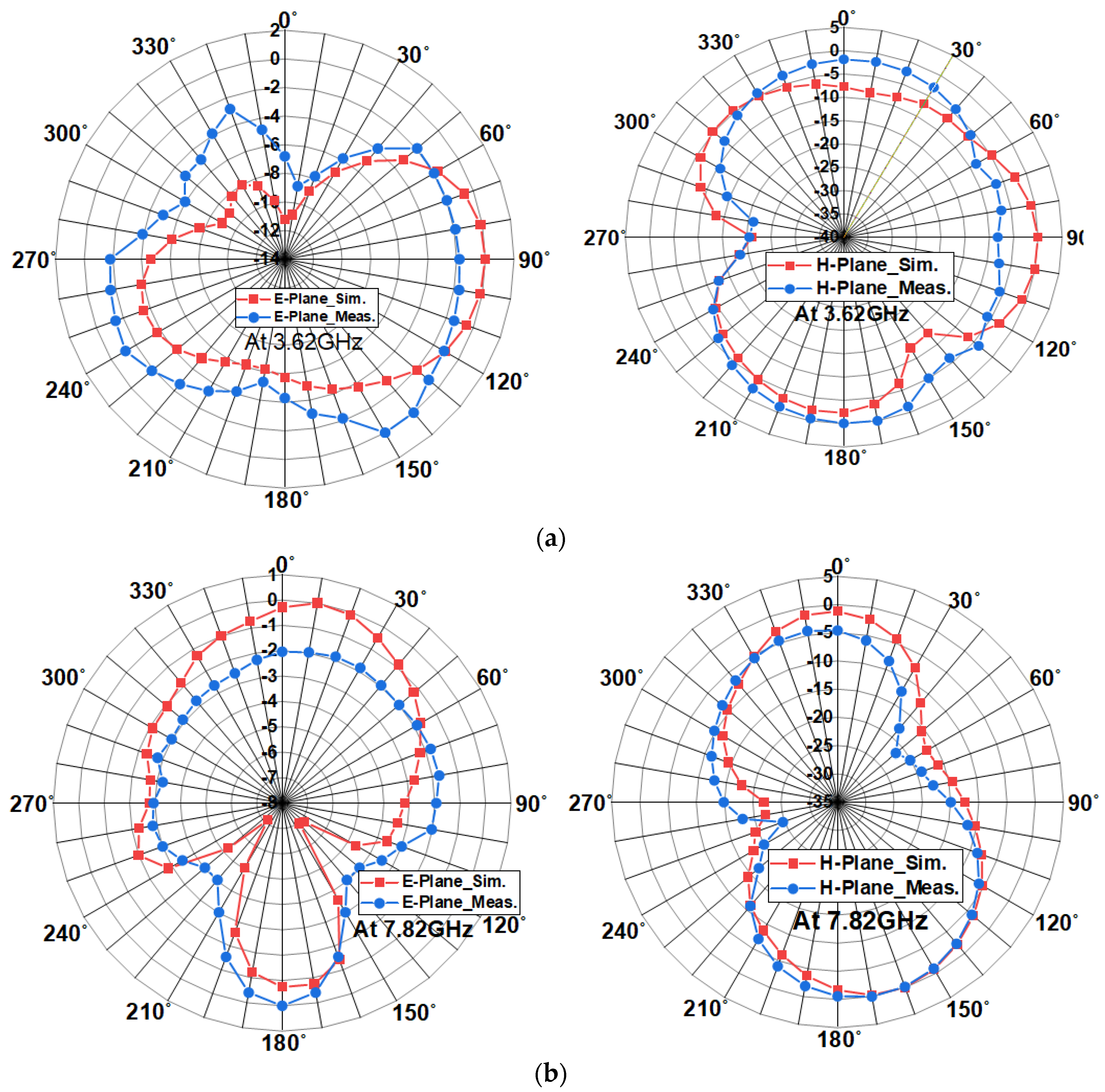
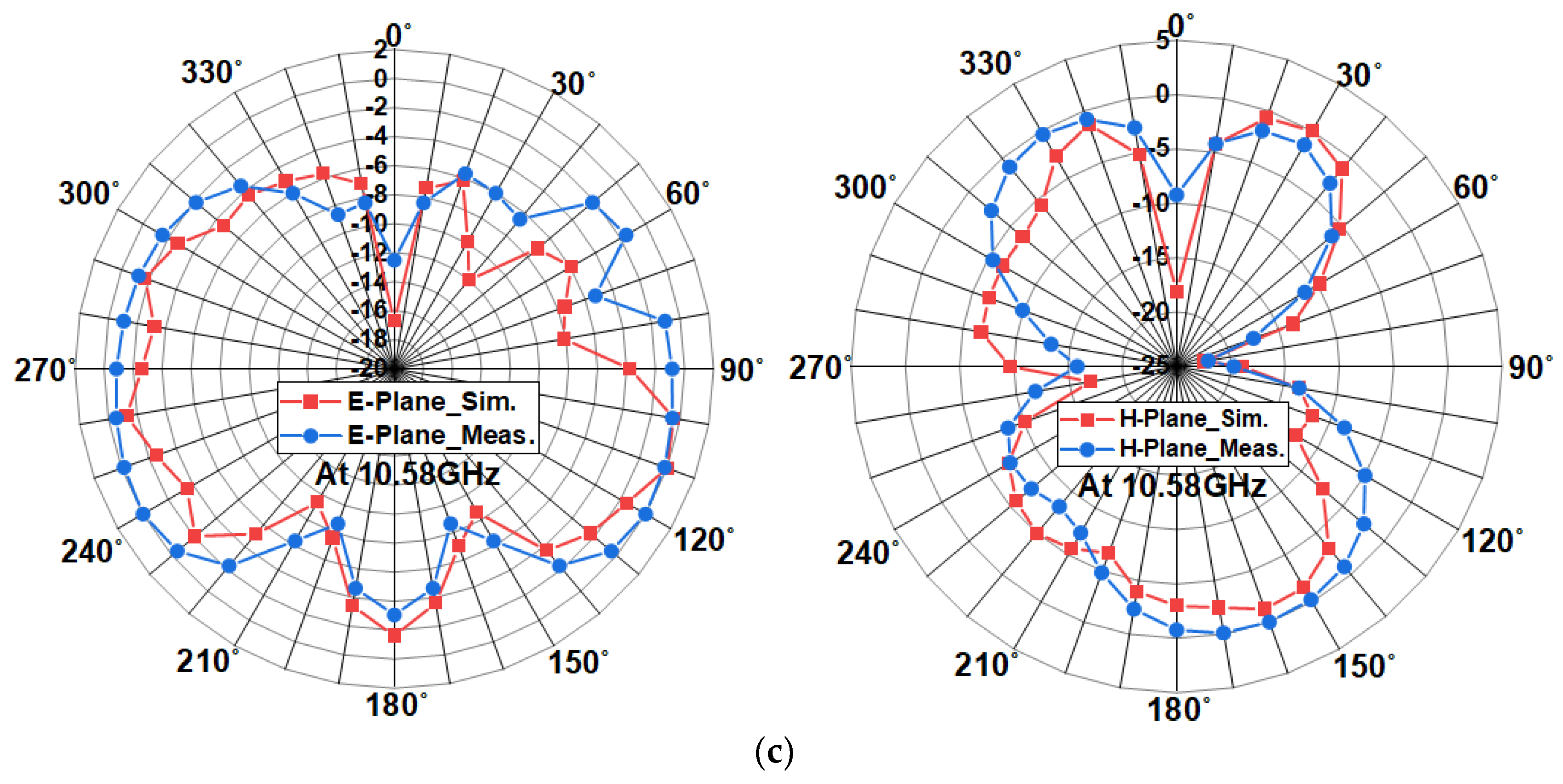
The proposed antenna was equipped with an 18 GHz anechoic chamber, and the measured and simulated radiation patterns in the E-plane with = 0 ° and in the H-plane with = 90 ° for a full range of θ from 0 °   t o   360 ° at three resonating frequencies of 3.62 GHz, 7.82 GHz, and 10.58 GHz are represented in Figure 15a–c. It is noticed that, for the proposed antenna with the FSS, the radiation pattern in the E-plane is leaf-shaped, while, in the H-plane, it is bidirectional and follows the shape of a figure of eight (“8”). The measured and simulated values are found to exhibit an excellent match with each other at all resonating frequencies. However, while the shapes of the radiation patterns in the E-plane and H-plane are nearly identical, they have differences in their gain values and magnitudes.

3.5. Antenna Gain Plots

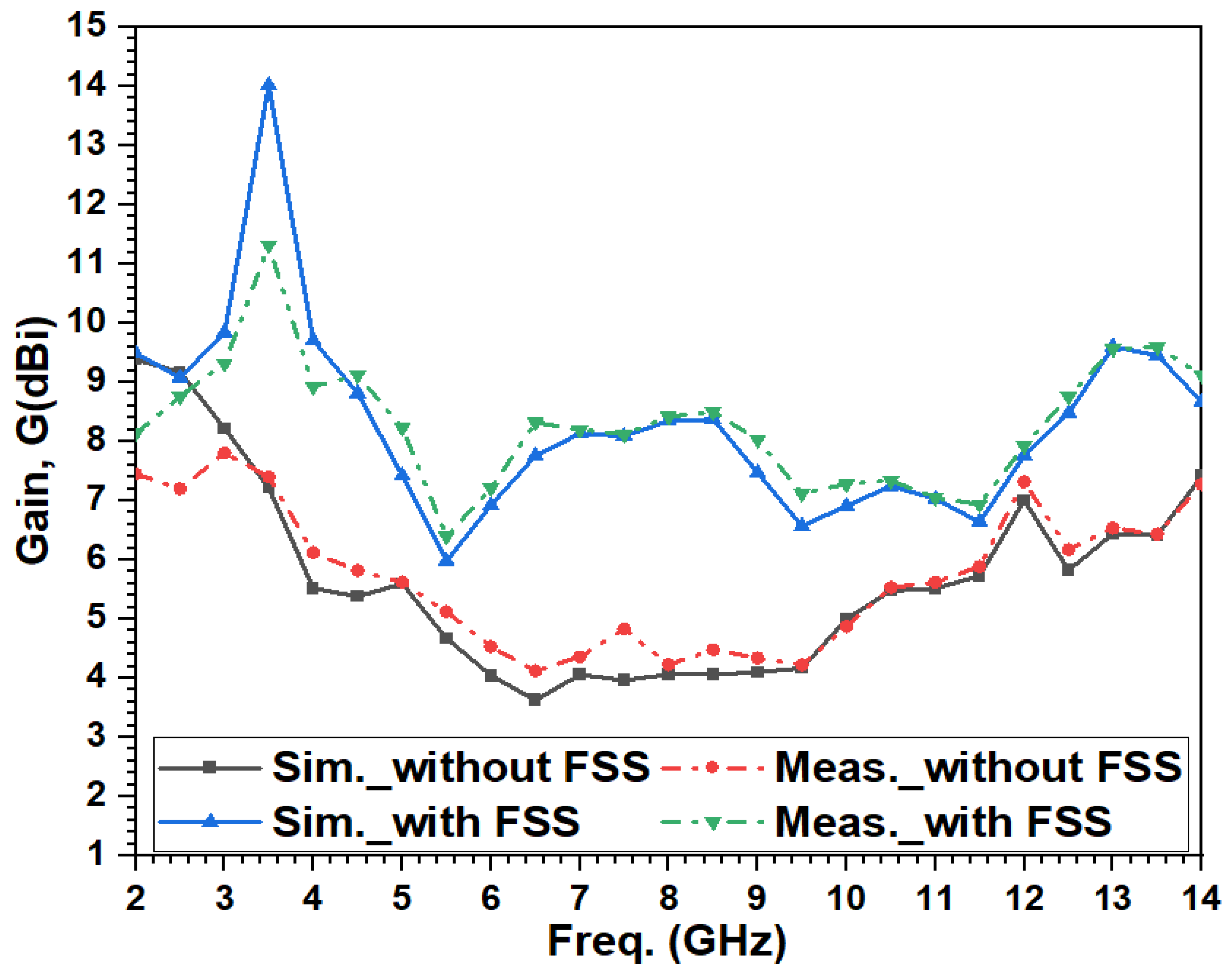
The simulated and measured gains of the proposed antenna for a frequency sweep from 2 GHz to 14 GHz are plotted in Figure 16. This comparison shows that the shapes of the simulated and measured antenna gains without and with an FSS follow each other and are in good agreement. It is noticed that the simulated gain with the FSS is enhanced in the overall frequency range, and a peak gain of 14.02 dBi is achieved at 3.5 GHz. An excellent gain enhancement is observed throughout the complete range of frequencies in comparison to the antenna simulated and measured without an FSS.

3.6. Current Density Distributions

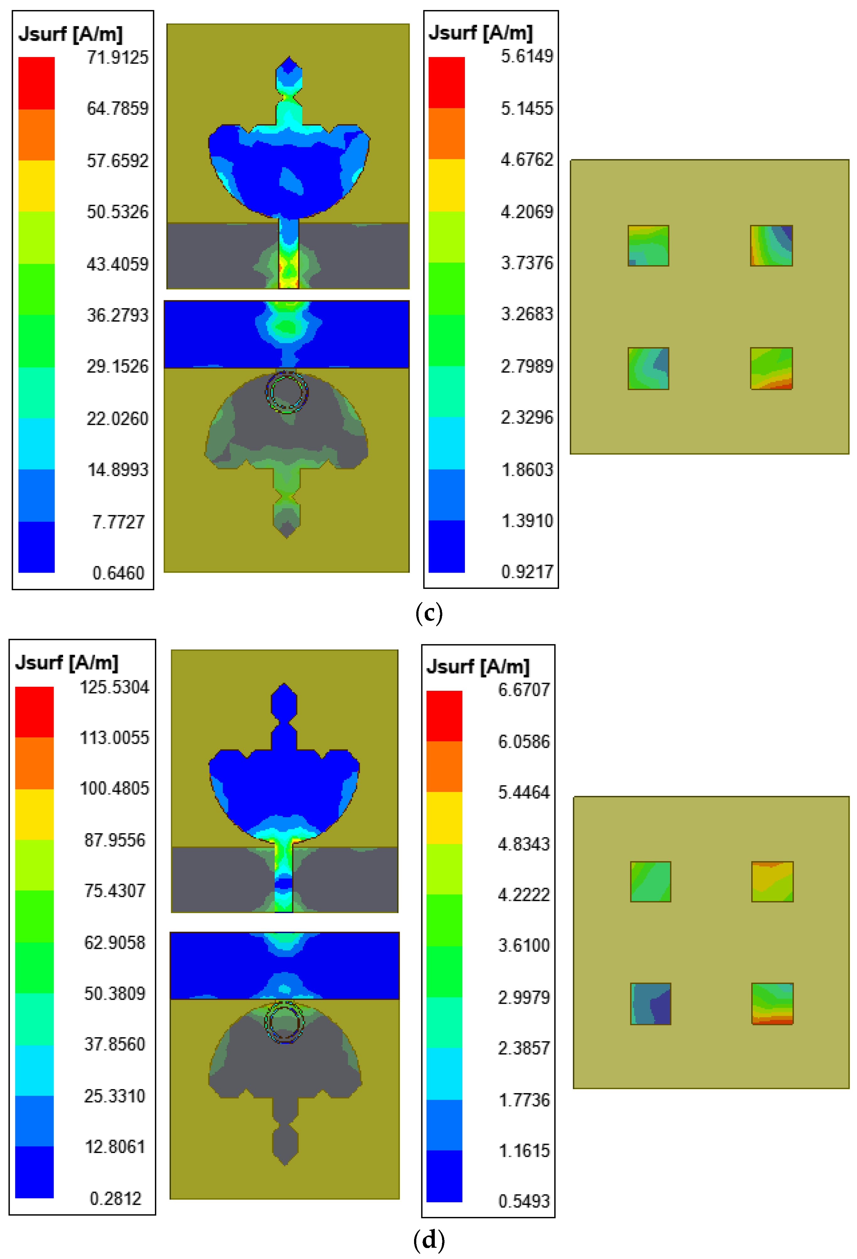
The magnitudes of the current density distributions of the proposed FSS antenna at two resonating frequencies at 3.5 GHz, 3.62 GHz, 7.82 GHz, and 10.58 GHz are illustrated in Figure 17a–e. The blue color in the FSS corresponds to the lowest current density, and the green and red colors indicate the highest current density magnitude corresponding to resonance. It is noticed that when the antenna is not loaded with an FSS, its current density distribution has the highest magnitude in the Koch section, whereas the semi-circular section and ground layer have the minimum current magnitudes. This results from the lower overall gain at a frequency of 3.5 GHz (Figure 17a). When the antenna is loaded with an FSS, the FSS works as a reflector as per the Fabry cavity interference principle, and most radiation is reflected towards the radiating element. This will enhance the main lobe power of the radiating patch and result in the directional enrichment of the antenna gain (Figure 17b–e). At resonating frequencies of 3.5 GHz and 3.62 GHz, the magnitude of the peak current in the semi-circular patch section is reduced, and all four stubs have a good amount of mutually coupled current in all four metallic stubs. On the other hand, the magnitude of the current density improves in the semi-circular section and reduces in the Koch fractal section at 7.82 GHz and 10.58 GHz.

3.7. Comparison with Similar Existing Antennas

The existing antennas described in the literature are compared in Table 7 with the proposed antenna regarding the resultant parameters. It is observed that the antenna’s FSS size and the materials used are the same for both the FSS and antenna; the FSS size may even be higher in comparison with the main radiator antenna’s size [49,51]. It is also noticed that the FSS layer exists either above (superstrate) or below (reflector) the antenna. Some antennas’ FSS layers are fabricated on certain substrates, while the patch is developed on another substrate [49,51]. The different substrates are used to create a hybrid effective cumulative material permittivity effect to control the gain and bandwidth. The air gap in the FSS results in frequency tuning, while the hybrid materials increase the overall cost of the antenna. Therefore, it is essential to ensure that the antenna is economical using low-cost materials, and the size of the FSS must be smaller as compared to the radiator. The FSS must be simple and less complicated. The proposed antenna takes all of these advantages into account.

4. Conclusions

A novel compact monopole concept based on a modified semi-circular Koch fractal patch antenna is measured and investigated. The FSS is used to address the reduced value of the gain due to the fractal operations and size miniaturization (36.67%). The advantage of the designed FSS is that it is simple, compact, economical (fabricated on low-cost FR-4), and easy to fabricate, and the size of the FSS is smaller than the existing antenna’s size, which is very rarely considered in the literature. The introduced FSS enhances the overall gain of the antenna from 9.37 dBi to 14.02 dBi and produces improved radiation characteristics. The proposed semi-circular Koch fractal patch antenna is suitable for 5G sub-6 GHz FR-1 n77 (3.3–3.8 GHz), n78 (3.3–4.2 GHz), and n79 (4.4–4.99 GHz), but it also results in the second band ranging from 6.99 GHz to 8.81 GHz and the third band from 10.22 to 10.92 GHz. Therefore, this antenna is also suitable for use in partial C-band operations. The antenna’s tuning and gain enhancement are achieved by adjusting the existing air gap between the antenna and FSS. The linearity plot of the frequency tuning with the air gap is present in the text. To validate the fabricated antenna’s results, it is measured using a VNA N9916A and an anechoic chamber. The measured reflection coefficients, gains, and radiation patterns are found to be in excellent agreement with the simulated reflection coefficients, antenna gains, and radiation patterns. This validates the antenna results. The measured antenna’s first resonating frequency matches the design frequency of 3.5 GHz. In the future, the same antenna could be modified using the Minkowski and other fractal techniques. Further, the FSS can be modified with metamaterials with electromagnetic band gap (EBG) structures and artificial magnetic conductors (AMC) for the enhancement of the bandwidth and gain over a wide range.

Author Contributions

A.V. and D.N.G. were fully responsible for the performance of this research work. Conceptualization, A.V. and D.N.G.; methodology, A.V. and D.N.G.; software, A.V. and D.N.G.; validation, A.V. and D.N.G.; formal analysis, A.V. and D.N.G.; investigation, A.V. and D.N.G.; resources, D.N.G.; data curation, A.V.; writing—original draft preparation, A.V. and D.N.G.; writing—review and editing, A.V. and D.N.G.; visualization, A.V. and D.N.G.; funding acquisition, A.V. and D.N.G. All authors have read and agreed to the published version of the manuscript.

Funding

This research received no external funding.

Institutional Review Board Statement

Not applicable as this research work did not involve humans or animals.

Informed Consent Statement

Not applicable.

Data Availability Statement

Data is contained within the article.

Acknowledgments

The authors are thankful to Gurukula Kangri (Deemed to be University), Haridwar, India, for conducting this research work, and Adana Alparslan Türkeş Science and Technology University, Türkiye, for providing the fabrication, measurement, and testing facilities for the antenna.

Conflicts of Interest

The authors declare no conflicts of interest.

References

  1. Werner, D.H.; Ganguly, S. An overview of fractal antenna engineering research. IEEE Antennas Propag. Mag. 2003, 45, 38–57. [Google Scholar] [CrossRef]
  2. Gianvittorio, J.P.; Rahmat-Samii, Y. Fractal antennas: A novel antenna miniaturization technique, and applications. IEEE Antennas Propag. Mag. 2002, 44, 20–36. [Google Scholar] [CrossRef]
  3. Nhlengethwa, N.L.; Kumar, P. Fractal microstrip patch antennas for dual-band and triple-band wireless applications. Int. J. Smart Sens. Intell. Syst. 2021, 14, 1–9. [Google Scholar] [CrossRef]
  4. Werner, D.H.; Haupt, R.L.; Werner, P.L. Fractal antenna engineering: The theory and design of fractal antenna arrays. IEEE Antennas Propag. Mag. 1999, 41, 37–58. [Google Scholar] [CrossRef]
  5. Nejdi, I.H.; Bri, S.; Marzouk, M.; Ahmad, S.; Rhazi, Y.; Ait Lafkih, M.; Hussein, M. UWB circular fractal antenna with high gain for telecommunication applications. Sensors 2023, 23, 4172. [Google Scholar] [CrossRef]
  6. Benkhadda, O.; Saih, M.; Ahmad, S.; Al-Gburi, A.J.A.; Zakaria, Z.; Chaji, K.; Reha, A. A miniaturized tri-wideband Sierpinski hexagonal-shaped fractal antenna for wireless communication applications. Fractal Fract. 2023, 7, 115. [Google Scholar] [CrossRef]
  7. Sediq, H.T.; Nourinia, J.; Ghobadi, C.; Mohammadi, B. A novel shaped ultrawideband fractal antenna for medical purposes. Biomed. Signal Process. Control 2023, 80, 104363. [Google Scholar] [CrossRef]
  8. Pandav, S.; Sadhukhan, G.; Das, T.K.; Behera, S.K.; Mohanty, M. π-shaped circularly polarized high-gain Minkowski fractal antenna for radar applications. Int. J. Commun. Syst. 2024, 37, e5648. [Google Scholar] [CrossRef]
  9. Kumar, A.; Dewan, B.; Khandelwal, A.; Shrivastava, K. On the devolvement of fractal antenna for IoT applications. Eng. Res. Express 2023, 5, 035026. [Google Scholar] [CrossRef]
  10. Kaur, H.; Chawla, P. Design and evaluation of a fractal wearable textile antenna for medical applications. Wirel. Pers. Commun. 2023, 128, 683–699. [Google Scholar] [CrossRef]
  11. Sabban, A. Novel Meta-Fractal Wearable Sensors and Antennas for Medical, Communication, 5G, and IoT Applications. Fractal Fract. 2024, 8, 100. [Google Scholar] [CrossRef]
  12. Sran, S.S.; Sivia, J.S. Design of a novel wearable hybrid fractal antenna for Wi-Fi, Bluetooth, and WiMAX applications. Wirel. Pers. Commun. 2023, 132, 737–755. [Google Scholar] [CrossRef]
  13. Dhara, R.; Govil, M.C.; Kundu, T. Application of theory of characteristics modes for bandwidth enhancement of a miniaturized Minkowski fractal antenna. IETE J. Res. 2023, 69, 5919–5934. [Google Scholar] [CrossRef]
  14. Varnikha, N.; Jothilakshmi, P. Modified Minkowski Multiband Fractal Antenna for Satellite Applications. Int. J. Microw. Opt. Technol. 2023, 18, 367. [Google Scholar]
  15. Paun, M.A.; Nichita, M.V.; Paun, V.A.; Paun, V.P. Fifth-generation fractal antenna design based on the Koch Snowflake geometry. A fractal theory application. Expert Syst. 2023, e13242. [Google Scholar] [CrossRef]
  16. Masroor, I.; Ansari, J.A. An ultrawideband Koch fractal patch antenna. Microelectron. Int. 2024, 41, 109–120. [Google Scholar] [CrossRef]
  17. Ezhumalai, A.; Ganesan, N.; Palaniappan, R. Koch snowflake fractal embedded octagonal patch antenna with hexagonal split ring for ultra-wide band and 5G applications. Prog. Electromagn. Res. C 2023, 135, 95–106. [Google Scholar] [CrossRef]
  18. Patel, K.; Behera, S.K. Design of Koch Curve-Based Fractal Antenna for Ultra-Wideband Applications. In Proceedings of the 2023 IEEE Microwaves, Antennas, and Propagation Conference (MAPCON), Ahmedabad, India, 11–14 December 2023; pp. 1–5. [Google Scholar]
  19. Gupta, M.; Mathur, V. Wheel shaped modified fractal antenna realization for wireless communications. AEU-Int. J. Electron. Commun. 2017, 79, 257–266. [Google Scholar] [CrossRef]
  20. Benavides, J.B.; Lituma, R.A.; Chasi, P.A.; Guerrero, L.F. A novel modified hexagonal shaped fractal antenna with multi band notch characteristics for UWB applications. In Proceedings of the 2018 IEEE-APS Topical Conference on Antennas and Propagation in Wireless Communications (APWC), Cartagena, Colombia, 10–14 September 2018; pp. 830–833. [Google Scholar]
  21. Suvarna, K.; Ramamurthy, N.; Vardhan, D. A tri-band miniaturized antenna using fractal defected ground structure for C/X and Ku-band applications. Prog. Electromagn. Res. M 2022, 113, 115–128. [Google Scholar] [CrossRef]
  22. Yu, Z.; Li, Y.; Lin, Z.; Ran, X. Design of window grille shape-based multiband antenna for mobile terminals. Int. J. Antennas Propag. 2021, 2021, 6684959. [Google Scholar] [CrossRef]
  23. Gupta, N.; Saxena, J.; Bhatia, K.S. Optimized metamaterial-loaded fractal antenna using modified hybrid BF-PSO algorithm. Neural Comput. Appl. 2020, 32, 7153–7169. [Google Scholar] [CrossRef]
  24. Kumar, D.; Ahmed, S. Modified ring shaped Sierpinski triangle fractal antenna for C-band and X-band applications. In Proceedings of the 2014 International Conference on Computational Intelligence and Communication Networks, Bhopal, India, 14–16 November 2014; pp. 78–82. [Google Scholar]
  25. Froumsia, D.; Dikoundou, J.E.; İnç, M.; Houwe, A.; Kolyang, K. Miniaturization and performance studies of rectangular microstrip patch antennae using Minkowski fractal for Ku band communications by inset feed technique. Researchsquare, 2022; Preprint. [Google Scholar]
  26. Kaur, M.; Sivia, J.S. ANN and FA-based design of hybrid fractal antenna for ISM band applications. Prog. Electromagn. Res. C 2020, 98, 127–140. [Google Scholar] [CrossRef]
  27. Swetha, A.; Naidu, K.R. Miniaturized antenna using DGS and meander structure for dual-band application. Microw. Opt. Technol. Lett. 2020, 62, 3556–3563. [Google Scholar] [CrossRef]
  28. Anguera, J.; Andújar, A.; Jayasinghe, J.; Chakravarthy, V.V.S.S.S.; Chowdary, P.S.R.; Pijoan, J.L.; Ali, T.; Cattani, C. Fractal Antennas: An Historical Perspective. Fractal Fract. 2020, 4, 3. [Google Scholar] [CrossRef]
  29. Sharma, N.; Bhatia, S.K. Comparative analysis of hybrid fractal antennas: A review. Int. J. RF Microw. Comput.-Aided Eng. 2021, 31, e22762. [Google Scholar] [CrossRef]
  30. Dahiya, A.; Anand, R.; Sindhwani, N.; Kumar, D.S. A novel multi-band high-gain slotted fractal antenna using various substrates for X-band and KU-band applications. Mapan 2021, 37, 175–183. [Google Scholar] [CrossRef]
  31. Jayarenjini, J.N. Meandered CPW-fed hexagonal ring fractal multi-band antenna loaded with labyrinth resonator. Researchsquare, 2022; Preprint. [Google Scholar]
  32. Shookooh, B.R.; Monajati, A.; Khodabakhshi, H. Theory, design, and implementation of a new family of ultra-wideband metamaterial microstrip array antennas based on fractal and Fibonacci geometric patterns. J. Electromagn. Eng. Sci. 2020, 20, 53–63. [Google Scholar] [CrossRef]
  33. Kodali, R.R.; Siddaiah, P.; Giriprasad, M.N. Arrow cross shape slotted fractal antenna with enhanced bandwidth for Wi-Fi/WIMAX/WLAN applications. Prog. Electromagn. Res. C 2022, 119, 115–124. [Google Scholar] [CrossRef]
  34. Kattimani, B.; Patil, R.R. A miniaturized design of vicsek snowflake-box fractal microstrip patch antenna using defective ground structure for wireless applications. Int. J. Microw. Wirel. Technol. 2022, 15, 112–119. [Google Scholar] [CrossRef]
  35. Kumar, M.B.; Jayappa, P. Sierpinski carpet fractal monopole antenna for ultra-wideband applications. Int. J. Electr. Comput. Eng. 2022, 12, 983–996. [Google Scholar]
  36. Varshney, A.; Cholake, N.; Sharma, V. Low-cost ELC-UWB fan-shaped antenna using parasitic SRR triplet for ISM band and PCS applications. Int. J. Electron. Lett. 2022, 10, 391–402. [Google Scholar] [CrossRef]
  37. Varshney, A.; Sharma, V.; Neebha, T.M.; Kumar, R. A compact low-cost impedance transformer-fed wideband monopole antenna for Wi-MAX N78-band and wireless applications. In Printed Antennas; CRC Press: Boca Raton, FL, USA, 2022; pp. 315–328. [Google Scholar]
  38. Singh, S.; Varshney, A.; Sharma, V.; Elfergani, I.; Zebiri, C.; Rodriguez, J. A Compact Off-Set Edge Fed Odd-Symmetric Hybrid Fractal Slotted Antenna for UWB and Space Applications. Prog. Electromagn. Res. B 2023, 102, 37–60. [Google Scholar] [CrossRef]
  39. Varshney, A.; Sharma, V.; Neebha, T.M.; Kumari, N.P. Notch-band eliminator wideband CSRR loaded monopole fractal antenna for ISM and PCS communications. World J. Eng. 2024, 21, 821–834. [Google Scholar] [CrossRef]
  40. Kushwaha, N.; Kumar, R. Design of a wideband high gain antenna using FSS for circularly polarized applications. Int. J. Electron. Commun. 2016, 70, 1156–1163. [Google Scholar] [CrossRef]
  41. Devarapalli, A.B.; Moyra, T.; Madhav, B.T.B. An FSS based broadband elliptical tree shaped antenna with augmented gain for wireless applications. IETE J. Res. 2023, 69, 7704–7716. [Google Scholar] [CrossRef]
  42. Chen, H.Y.; Tao, Y. Performance improvement of a U-slot patch antenna using a dual-band frequency selective surface with modified Jerusalem cross elements. IEEE Trans. Antennas Propag. 2011, 59, 3482–3486. [Google Scholar] [CrossRef]
  43. Sah, S.; Mittal, A.; Tripathy, M.R. High gain dual band slot antenna loaded with frequency selective surface for WLAN/fixed wireless communication. Microw. Opt. Technol. Lett. 2019, 61, 519–525. [Google Scholar] [CrossRef]
  44. Peddakrishna, S.; Khan, T. Performance improvement of slotted elliptical patch antenna using FSS superstrate. Int. J. RF Microw. Comput.-Aided Eng. 2018, 28, e21421. [Google Scholar] [CrossRef]
  45. Zhu, H.; Yu, Y.; Li, X.; Ai, B. A wideband and high gain dual-polarized antenna design by a frequency-selective surface for WLAN application. Prog. Electromagn. Res. C 2014, 54, 57–66. [Google Scholar] [CrossRef]
  46. Bouslama, M.; Traii, M.; Gharsallah, A.; Denidni, T.A. Analysis of antenna gain enhancement using new frequency selective surface superstate. Microw. Opt. Technol. Lett. 2016, 58, 448–452. [Google Scholar] [CrossRef]
  47. Anand, Y.; Nath, V. Dual Polarized Gain Enrichment of a Low-Cost Multi-Band Circular Fractal Antenna Using Tunable Stacked FSS for Wireless Applications. Iran J. Sci. Technol. Trans. Electr. Eng. 2024, 48, 1373–1391. [Google Scholar] [CrossRef]
  48. Anand, Y.; Nath, V. Gain enhancement of antenna using tuned complementary FSS for wireless communication. Int. J. Electron. 2024, 1–27. [Google Scholar] [CrossRef]
  49. Ara, S.; Nunna, P.K. Gain enhancement of a monopole antenna using frequency selective surface for sub 6 GHz band applications. Int. J. Adv. Technol. Eng. Explor. 2023, 10, 840–857. [Google Scholar]
  50. Jing, H.; He, G.; Wang, S. Design of a flexible cylindrical antenna with rotatable curved frequency selective surface for omnidirectional high-gain applications. Int. J. Antennas Propag. 2023, 2023, 6553980. [Google Scholar] [CrossRef]
  51. Ara, S.; Nunna, P.K. Gain and radiation pattern enhancement using ANN-based reflector antenna for full 5G Sub-6 GHz applications. Int. J. Adv. Technol. Eng. Explor. 2024, 11, 644–667. [Google Scholar]
  52. Balanis, C.A. Antenna Theory Analysis and Design, 2nd ed.; Reprints; John Wiley and Sons: Hoboken, NJ, USA, 2009; pp. 755–756. [Google Scholar]
  53. Singh, D.; Kumar, A.; Meena, S.; Agarwala, V. Analysis of frequency selective surfaces for radar absorbing materials. Prog. Electromagn. Res. B 2012, 38, 297–314. [Google Scholar] [CrossRef]
Figure 1. Koch fractal principle.
Applsci 14 09022 g001
Figure 2. Development of Koch fractal iteration 0 stage.
Applsci 14 09022 g002
Figure 3. Fractal antenna patch development: (a) iteration 0, (b) iteration 1, and (c) iteration 2.
Applsci 14 09022 g003
Figure 4. Frequency-selective surface: (a) FSS structure and (b) equivalent circuit of FSS.
Applsci 14 09022 g004
Figure 5. Step-by-step design development.
Applsci 14 09022 g005
Figure 6. Koch fractal antenna (a) with FSS; (b) side view; (c) top patch, bottom ground, and FSS view; and (d) antenna 3D model.
Applsci 14 09022 g006
Figure 7. Split ring resonator (SRR) structure designed at 3.5 GHz.
Applsci 14 09022 g007
Figure 8. Effects of iterations.
Applsci 14 09022 g008
Figure 9. Effects of reduced ground and SRR loading.
Applsci 14 09022 g009
Figure 10. Miniaturization process.
Applsci 14 09022 g010
Figure 11. FSS loading effect on miniaturized Koch fractal antenna: (a) frequency tuning and gain enhancement and (b) effect of air gap on resonance frequency and cumulative effective permittivity.
Applsci 14 09022 g011
Figure 12. SRR loading effect on FSS miniaturized Koch fractal antenna.
Applsci 14 09022 g012
Figure 13. FSS loading effect on miniaturized Koch fractal antenna: (a) antenna radiator (top view), (b) antenna ground (bottom view), (c) FSS structure, and (d) antenna prototype model.
Applsci 14 09022 g013aApplsci 14 09022 g013b
Figure 14. Simulated vs. measured reflection coefficients: (a) without FSS and (b) with FSS.
Applsci 14 09022 g014
Figure 15. Simulated vs. measured radiation patterns in E-plane and H-plane at (a) 3.62 GHz, (b) 7.82 GHz, and (c) 10.58 GHz.
Applsci 14 09022 g015aApplsci 14 09022 g015b
Figure 16. Simulated vs. measured antenna gains.
Applsci 14 09022 g016
Figure 17. Current density distribution of the proposed fractal antenna: (a) current density without FSS at 3.5 GHz, (b) current density with FSS at 3.5 GHz, (c) current density with FSS at 3.62 GHz, (d) current density with FSS at 7.82 GHz, and (e) current density with FSS at 10.58 GHz.
Applsci 14 09022 g017aApplsci 14 09022 g017bApplsci 14 09022 g017c
Table 1. Dimensions of the proposed Koch fractal antenna.
Symbolic DesignationDescriptionOptimized Dimensions (mm)
WSSubstrate width35.94
LSSubstrate length38.97
aePatch radius11.98
WFFeed width3.0
LF = λ g 4 Feed length10.30
WGGround width35.94
LGGround length9.7
RoutOuter ring radius of SRR3.1
RinInner ring radius of SRR2.35
gSRR gap0.50
WSRR width0.25
SGap between SRR rings0.28
KKoch curve dimension16.94
K0 = K 3 0 Iteration 016.94
K1 = K o 3 1 Iteration 17.98
K2 = K o 3 2 Iteration 21.882
LFSSLength of FSS33.96
WFSSWidth of FSS35.94
xFSS square edge length5
yGap between two squares of FSS10
hHeight of substrates1.6
HGap between substrates7.0
Table 2. Effects of fractals in patch development.
Iterationfr
(GHz)
S11
(dB)
−10 dB BW
(GHz)
Gain at fr
(dBi)
Gain at 3.5 GHz (dBi)Applications
Iteration 0
(modified circular patch)
3.26−24.971.51 (2.67–4.18)21.928.36n77, n78,
C-band and X-band
8.12−44.824.68 (4.88–9.56)6.64
11.54−17.742.39 (10.46–12.85)9.30
Iteration 13.20, 4.70−21.70, −20.922.24 (2.71–4.95)12.81, 10.5812.37n77, n78, n79, C-band and X-band
8.0−34.883.74 (5.78–9.52)6.0
11.90−17.282.80 (10.28–13.08)9.53
Iteration 23.20, 4.52−16.84, −18.771.99 (2.72–4.71)12.08, 9.9411.80n77, n78, n79, C-band and X-band
7.64, 11.91−28.03, −17.786.95 (5.75–12.70)6.30, 9.57
Table 3. SRR loading with reduced ground.
CaseGround
(mm)
fr
(GHz)
S11
(dB)
−10 dB BW
(GHz)
Gain (dBi)
at fr
Gain (dBi)
at 3.5 GHz
Iteration-2
antenna
Full ground
(46.15 mm)
9.50−21.130.43 (9.26–9.69)6.357.48
Iteration-2
antenna
50% ground
(23.075 mm)
9.56−11.090.38 (9.43–9.71)5.075.05
10.82−14.680.58 (10.54–11.12)14.24
13.58−12.641.04 (12.98–14.02)11.93
Iteration-2
antenna
11.983.26−13.740.52 (3.03–3.55)9.518.46
4.88−32.470.25 (4.77–5.02)8.59
8.66−14.410.97 (8.18–9.15)7.59
12.08−13.101.33 (11.39–12.72)9.44
Iteration-2
antenna
10.983.26−26.300.96 (2.84–3.80)12.8912.36
4.76−14.930.31 (4.60–4.91)11.18
8.60−22.933.06 (6.30–9.36)7.05
12.20−16.722.22 (11.02–13.24)8.14
Iteration-2
antenna
10.213.20, 4.58−22.48, −14.962.04 (2.74–4.78)13.58, 9.5812.22
8.18−39.873.68 (5.82–9.47)6.25
12.08−21.012.40 (10.42–12.82)10.55
Iteration-2
antenna
10.13.20, 4.58−24.64, −15.832.06 (2.69–4.75)13.09, 11.0911.81
8.06−54.663.61 (5.82–9.43)6.29
12.08−20.542.48 (10.37–12.85)10.71
Iteration-2 antenna + SRR10.13.26−25.841.27 (2.75–4.02)10.7210.08
4.70−16.500.49 (4.36–4.85)10.29
6.92−13.082.26 (5.91–8.17)5.98
12.14−14.522.38 (10.29–12.67)8.31
Iteration-2 antenna + SRR9.73.26, 4.58−14.34, −17.661.89 (2.89–4.76)16.66, 9.0615.11
6.50, 7.52−27.98, −29.503.55 (5.65–9.20)12.67, 5.84
12.32−14.742.53 (10.47–13.0)8.55
Table 4. Antenna miniaturization.
MiniaturizationAntenna
Size (mm2)
WS × LS
fr
(GHz)
S11
(dB)
−10 dB BW (GHz)Gain
(dBi)
at fr
Gain at 3.5 GHz
(dBi)
Primary antenna
WS = 4ae = 47.92 mm
LS = LF + 3ae = 46.15 mm
47.92 × 46.153.26, 4.58−14.34, −17.661.87 (2.89–4.76)16.66, 9.0615.11
6.50, 7.52−27.98, −29.503.55 (5.65–9.20)12.67, 5.84
12.32−14.742.53 (10.47–13.0)8.55
Reduced width
WS = 3ae = 35.94 mm
LS = LF + 3ae = 46.15 mm
35.94 × 46.153.44−37.921.68 (2.90–4.58)12.9211.96
7.82−14.081.66 (6.89–8.55)6.25
10.16−12.631.88 (9.43–11.31)8.05
Reduced width
WS = 2ae = 23.96 mm
LS = LF + 3ae = 46.15 mm
23.96 × 46.153.44−13.020.84 (3.08–3.92)10.9711.02
7.70−26.613.23 (5.16–8.39)5.99
10.88−10.740.85 (10.44–11.29)7.83
13.64−34.641.58 (12.52–14.10)9.85
Miniaturized antenna
WS = 3ae = 35.94 mm
LS = LF + 2ae + 3h = 38.97 mm
35.94 × 38.973.44−42.371.71 (2.90–4.61)9.529.37
7.70−13.961.59 (6.86–8.45)6.15
10.16−13.211.33 (9.47–10.80)7.41
Table 5. Frequency tunning using FSS loading.
FSS LoadingGap (H)
between Substrates
fr
(GHz)
S11
(dB)
−10 dB BW (GHz)Gain (dBi)
at fr
Gain at 3.5 GHz
(dBi)
Parent antenna with FSS below the radiator (distance between radiator and FSS = 3.0 mm)H = 2.2 mm3.38−31.322.84–4.3610.2910.46
7.46−20.656.20–8.788.59
11.78−12.4310.93–12.488.39
Parent antenna with FSS below the radiator (distance between radiator and FSS = 4.6 mm)H = 3.0 mm3.44−30.362.85–4.478.438.31
8.0−20.526.28–8.998.59
11.42−12.1710.70–11.936.40
Primary antenna with FSS below the radiator (distance between radiator and FSS = 5.4 mm)H = 3.8 mm3.50−27.852.86–4.537.147.14
(tuned)
7.70−19.316.51–8.748.47
11.18−10.4410.78–11.566.53
Primary antenna with FSS below the radiator (distance between radiator and FSS = 6.2 mm)H = 4.6 mm3.56−27.492.87–4.586.937.08
7.70−16.266.62–8.718.53
Primary antenna with FSS below the radiator (distance between radiator and FSS = 7.0 mm)H = 5.4 mm3.56−29.152.86–4.587.937.87
7.76−14.916.71–8.778.31
10.76−10.6610.22–11.257.91
Primary antenna with FSS below the radiator (distance between radiator and FSS = 7.8 mm)H = 6.2 mm3.56−32.112.89–4.618.128.19
7.82−13.486.89–8.778.03
10.82−10.5110.56–11.048.0
Primary antenna with FSS below the radiator (distance between radiator and FSS = 8.6 mm)H = 7.0 mm3.62−32.292.87–4.6211.3714.02
(Gain Enhan.)
7.82−13.756.99–8.818.21
10.58−10.9010.22–10.927.20
Parent antenna with FSS below the radiator (distance between radiator and FSS = 9.4 mm)H = 7.8 mm3.62−33.742.88–4.648.278.49
7.88−13.047.04–8.638.08
10.52−11.8810.20–10.868.45
Table 6. Frequency tunning using SRR loading.
CaseGround Length
(mm)
fr
(GHz)
S11
(dB)
−10 dB BW
(GHz)
Gain (dBi)
at fr
Gain (dBi)
at 3.5 GHz
Antenna without SRR without FSS
(35.94 × 38.97 mm2)
9.73.44−33.141.69 (2.91–4.60)13.5013.38
8.48−31.034.02 (6.92–10.94)6.51
Antenna with SRR without FSS
(35.94 × 38.97 mm2)
9.73.44−42.371.71 (2.90–4.61)9.529.37
7.70−13.961.59 (6.86–8.45)6.15
10.16−13.211.33 (9.47–10.80)7.41
Antenna with SRR + FSS
(35.94 × 38.97 mm2)
9.7
(FSS size
35.94 × 33.96 mm2
Gap, H = 7.0 mm)
3.62−32.291.75 (2.87–4.62)11.3714.02
(Gain Enhancement)
7.82−13.751.81 (6.99–8.81)8.21
10.58−10.900.70 (10.22–10.92)7.20
Table 7. Comparison with existing antennas in the literature.
Ref.
[Year]
fr
(GHz)
Antenna Size
(mm3)
MUC and FSS Size (mm3)H
(mm)
f0
(GHz)
BW
fL–fH
(GHz)
GEnhan. (dBi)Cost
[40]
Kushwaha and Kumar, 2016
3.425,
8.94
45
× 50
× 1.6
−51.67%
(size increased)
23 × 23 × 1.6
(UC)
150 × 150 × 1.6 (FSS)
253.52.2–4.83–4Low
[41]
Devarapalli et al., 2023
3,
8.75
44
× 40
× 1.6
−33.78%
(size increased)
4.5 × 4.5
(UC)
44 × 40 × 1.6
(FSS)
NA3.52.49–4.36,
7.96–9.92
6.15 to
9.48
Low
[42]
Chen, and Tao, 2011
2.45,
5.8
30
× 54
× 4.4
−242.1%
(size increased)
32 × 32 × 2.8
(UC)
96 × 64 × 3.2
(FSS)
4.42–6G2.38–2.73
3.28- 5.8
4.69,
5.64
Low
[43]
Sah et al. 2019
3.53,
6.2
105 ×
175 ×
1.6
−1661.95%
(size increased)
15 × 25 × 1.6
(UC)
105 × 175 × 1.6 (FSS)
493.53.48–3.65
5.75–6.37
13.3,
13.90
Low
[44] Peddakrishna and Khan,
2018
5.250
× 50
× 1.6
−144.14%
(size increased)
7.02 × 7.02 × 1.6 (UC)
50 × 50 × 1.6 (FSS)
28.55.385.07–5.562.5 to 5.1Low
[45]
Zhu et al., 2014
5.6106
× 106
× 1.6
0%
(not miniaturized)
24 × 24 × 1.6
(UC)
106 × 106 × 1.6 (FSS)
335.55.3–6.34.7 to 9.8Low
[46] Bouslama et al., 20165.8140 ×
140 ×
1.57
0%
(not miniaturized)
46.5 × 46.5 × 0.127 (UC)
140 × 140 × 0.127 (FSS)
25
(above patch)
6.05.7–6.25.3 to 12.0High
[47]
Anand and Nath, 2024
6.0, 9.05, 11.5621.13 × 24.81 ×
1.6
−35.36%
(size increased)
21.13 × 24.81
× 1.6
(CFSS)
6.4
(below patch)
6.06.43–6.72
8.85–9.33 10.5–13.22
5.25 to 8.49Low
[48]
Anand and Nath, 2024
4.04,
5.76,
7.64
16.8 ×
26.72 ×
1.6
0%
(not miniaturized)
32.2 × 26.72 ×
1.6(FSS)
2.0
(above patch)
5.03.56–4.63,
5.17–6.22, 6.74–8.22
4.22 to 8.98Low
[49] Ara and Nuna, 20245.549 × 49 ×
1.588
−109.13%
(size increased)
49 × 49 ×
1.588 (FSS)
5.0
(below patch)
5.83.91–6.444.41 to 8.99Medium
[50]
Jing et al.
2023
5.8950 × 28 ×
0.1
Polyimide (PI)substrate
0%
(not miniaturized)
102 × 102 ×
1.588 (FSS)
40
(below patch)
2.42.18–2.90
3 to 8.31Medium
[51]
Ara and Nuna, 2023
5.8949 × 49 ×
1.588
−83.2%
(size increased)
49 × 49 ×
1.588 (FSS)
6.4
(below patch)
5.83.91–6.44
2.87 to 7.76Medium
Proposed
Work
3.62
7.82
10.58
35.94
× 38.97
× 1.6
Miniaturized (36.67%)5 × 5
(UC)
35.94 × 33.96 × 1.6 (FSS)
7.0
(below patch)
3.52.87–4.62
6.99–8.81
10.22–10.92
9.37 to 14.02Low
fr = resonating frequency; UC = unit cell; H = gap between substrates; f0 = design frequency; BW = −10 dB bandwidth; GEnhan. = gain enhancement; M = radiator miniaturization rate with conventional antenna.
Disclaimer/Publisher’s Note: The statements, opinions and data contained in all publications are solely those of the individual author(s) and contributor(s) and not of MDPI and/or the editor(s). MDPI and/or the editor(s) disclaim responsibility for any injury to people or property resulting from any ideas, methods, instructions or products referred to in the content.