Article

Comprehensive Evaluation Method for High-Performance Milling of Inconel 718 Alloy

by
Paweł Piorkowski
*,
Wojciech Borkowski
and
Waclaw Skoczynski
Faculty of Mechanical Engineering, Wroclaw University of Science and Technology, 50-370 Wroclaw, Poland
*
Author to whom correspondence should be addressed.
Appl. Sci. 2024, 14(19), 9023; https://doi.org/10.3390/app14199023 (registering DOI)
Submission received: 10 September 2024 / Revised: 21 September 2024 / Accepted: 25 September 2024 / Published: 6 October 2024

Abstract

:
The aim of this paper was to develop and verify a method for evaluating the high-performance milling of Inconel 718 alloy under accelerated tool wear conditions. The method considered parameters such as cutting-force components, total machine power consumption, cutting-edge wear, and material removal rate. The study compared high-feed milling and plunge milling, using sets of cutting parameters that are appropriate for both techniques. The results indicate that high-feed milling was more efficient, achieving higher material removal rates and lower tool wear. On the other hand, plunge milling was characterized by a lower axial force component (Fz), which can positively affect machining accuracy. The paper highlights that the proposed evaluation method can also be applied to other hard-to-machine materials, and plunge milling offers a competitive alternative for roughing operations in the milling of Inconel 718 alloy.

1. Introduction

Inconel alloys, being nickel-based superalloys, are characterized by exceptional mechanical strength and corrosion resistance at high temperatures, making them invaluable in the aerospace, energy, and chemical industries. However, these very properties also make the machining of Inconel alloys a significant technological challenge. The issues associated with machining these materials include rapid tool wear, intense heat generation in the cutting zone, and the formation of residual stresses, which can reduce the durability of the machined components [1]. In response to these challenges, researchers are developing and implementing advanced methods aimed at improving the machinability of Inconel alloys. Examples include advanced cooling techniques, such as cryogenic machining, which significantly extends tool life and enhances surface quality [2], and minimum quantity lubrication (MQL) enhanced with nanoparticles, which reduces energy consumption and improves process efficiency [3,4]. One such innovative method is also ultrasonic-assisted milling, which improves process stability and reduces cutting forces, which is particularly important when machining alloys such as Inconel 718 [5].
The milling of Inconel alloys using carbide and ceramic inserts differs significantly in terms of performance, tool durability, and the quality of the machined surface. Ceramic tools, such as those made from SiAlON, are particularly effective in roughing operations, where high cutting speeds are essential for the rapid removal of large volumes of material. Research revealed that ceramic tools achieve a higher material removal rate (MRR) compared to carbide tools, making them more suitable for roughing operations [6]. Meanwhile, it has been emphasized that milling with ceramic inserts allows for a significant reduction in machining time, which is especially advantageous in large-scale production [7]. However, for finishing operations, where surface quality and dimensional accuracy are paramount, carbide inserts prove to be more effective.
It was observed that finishing milling with carbide tools generates lower residual stresses and provides better surface quality compared to ceramic tools [8]. Carbide tools, particularly those with PVD or CVD coatings, exhibit superior wear resistance at lower cutting speeds, which results in reduced surface damage and higher machining precision [9,10]. Consequently, while ceramic tools are favored for roughing operations due to their efficiency, carbide tools dominate in finishing operations, where quality and precision are critical.
The milling of Inconel alloys using ceramic inserts requires specific parameters, including high cutting speeds, which are crucial for efficient material removal and extended tool life. Ceramic tools, particularly those made from materials such as SiAlON, are used at cutting speeds ranging from 250 m/min to even 900 m/min, depending on the specifics of the process and the type of tool. For example, it has been indicated that an optimal cutting speed for ceramic tools is around 250 m/min, allowing for a compromise between tool wear and tool longevity [11]. Conversely, it was described that, during high-speed milling, up to 900 m/min, SiAlON tools exhibit a significantly enhanced performance, albeit at the cost of increased residual stresses in the machined material [12]. Research demonstrated that, at cutting speeds ranging from 900 to 1100 m/min, it is possible to achieve a significant increase in the material removal rate (MRR), making these tools exceptionally effective for roughing operations [7]. Such high cutting speeds can lead to localized melting of the microstructure of Inconel 718, which reduces cutting forces, as previously observed [13].
In addition to the previously discussed methods, research on the machining of Inconel alloys highlights the need to optimize the cutting parameters and the tool geometry to improve surface quality and reduce residual stresses. It has been demonstrated that the use of “wiper” inserts during the face milling of Inconel 625 enhances the surface integrity and extends tool life [14]. Further investigations into residual stresses after milling Inconel 718 confirmed that selecting the appropriate production parameters is crucial for minimizing stresses, which can impact the durability of components [8].
The optimization of the cutting parameters, such as spindle speed, feed rate, and depth of cut, is crucial for achieving a high surface quality, as demonstrated by studies focusing on the machining of Inconel 601 [15]. Additionally, tool geometry parameters, such as rake angle and helix angle, have a significant impact on cutting forces and cutting temperature, as confirmed in prior research [16]. Further research on the machining of Inconel 718 using carbide-coated tools showed that the appropriate selection of a tool coating can significantly reduce tool wear and improve surface roughness [17].
Modern techniques, such as laser-assisted milling (LAM) and induction-assisted milling, represent innovative approaches to enhancing the cutting efficiency of Inconel alloys. It has been demonstrated that laser-assisted milling leads to a reduction in cutting forces and an improvement in surface quality, which is particularly important for precision finishing operations [18]. Similarly, research showed that induction-assisted milling reduces tool wear and improves process stability, which is crucial in the machining of Inconel 718 [19].
The machining of Inconel alloys, particularly with the use of advanced ceramic tools, presents a significant technological challenge due to the high hardness and wear resistance of these materials. Analysis of the application of Si3N4 tools in the milling of Inconel 718 showed that such tools can significantly reduce cutting forces, thereby improving the overall process efficiency [20]. Simultaneously, research highlighted the benefits of using nanoparticle suspension lubrication, which not only enhances surface quality but also improves the energy efficiency of the machining process for Inconel 800 [4].
One of the key aspects that requires special attention is the impact of machining parameters on material deformation. An analysis of deformation during the continuous milling of Inconel 718 indicated that the proper optimization of parameters such as cutting speed and feed rate can significantly reduce deformation and improve machining quality [21]. Further research examined the effect of tool geometry and cutting speed on the machinability of Inconel 718, demonstrating that the appropriate selection of these parameters is crucial for process efficiency and tool longevity [22].
In the context of sustainable development, a comparison of the additive and subtractive methods in the production of Inconel 718 components evaluated time costs and CO2 emissions, highlighting the importance of selecting the appropriate manufacturing technology for addressing global environmental challenges [23]. Meanwhile, a review of the current knowledge on surface integrity after machining nickel-based alloys pointed out the risk of white-layer formation, which can negatively affect the fatigue life of components [24].
Research on the high-speed dry milling of Inconel 718 using SiAlON tools demonstrated that the proper optimization of the process parameters, such as cutting speed, can lead to a reduction in the cutting forces and an extension of tool life [13]. Additionally, findings on the machining of Inconel 718 emphasized the critical role of cutting temperature, which directly affects tool wear and surface quality [25].
A common feature of most of the publications described above is the use of various cutting parameters and conditions aimed at assessing the changes associated with the introduction of innovative machining solutions. However, these results are difficult to compare due to differences in the experimental setups. The literature contains numerous examples of identifying which factors and parameters influence specific elements during the machining of Inconel alloys, and to what extent. Several studies have analyzed the impact of spindle speed, feed rate, and depth of cut on cutting forces [26,27]. Additionally, the influence of spindle speed, feed rate, and depth of cut on both cutting forces and power consumption has been examined [28]. Other research studied the effect of these parameters on tool life [29], while further investigations focused on the impact of spindle speed and feed rate on tool longevity [30]. The influence of the same factors on cutting forces and tool wear has also been explored [31]. These parameters often have ambiguous effects on the outcomes, and considering some factors and effects in isolation from others, they do not provide a complete understanding of Inconel milling. It has been suggested that methods such as GRA, TOPSIS, or fuzzy logic could be utilized to optimize the milling process of Inconel alloys [32]. GRA, in particular, yields promising results, as it does not require determining the weighting factors of individual process-influencing parameters, which, as noted, often vary in the literature [33]. Most studies focus on analyzing a maximum of 2–3 parameters, which is a relatively small number considering the capabilities of GRA-based methods. Therefore, it was decided that the designed method would analyze as many as four parameters. These parameters would be related not only to the cutting process itself but also to the cutting machine. For this reason, the energy consumption of the machine tool was considered, which has not been accounted for in similar studies, yet it is becoming an increasingly important aspect in the context of sustainable machining. We believe this highlights a research gap that we aim to address by presenting the developed method.

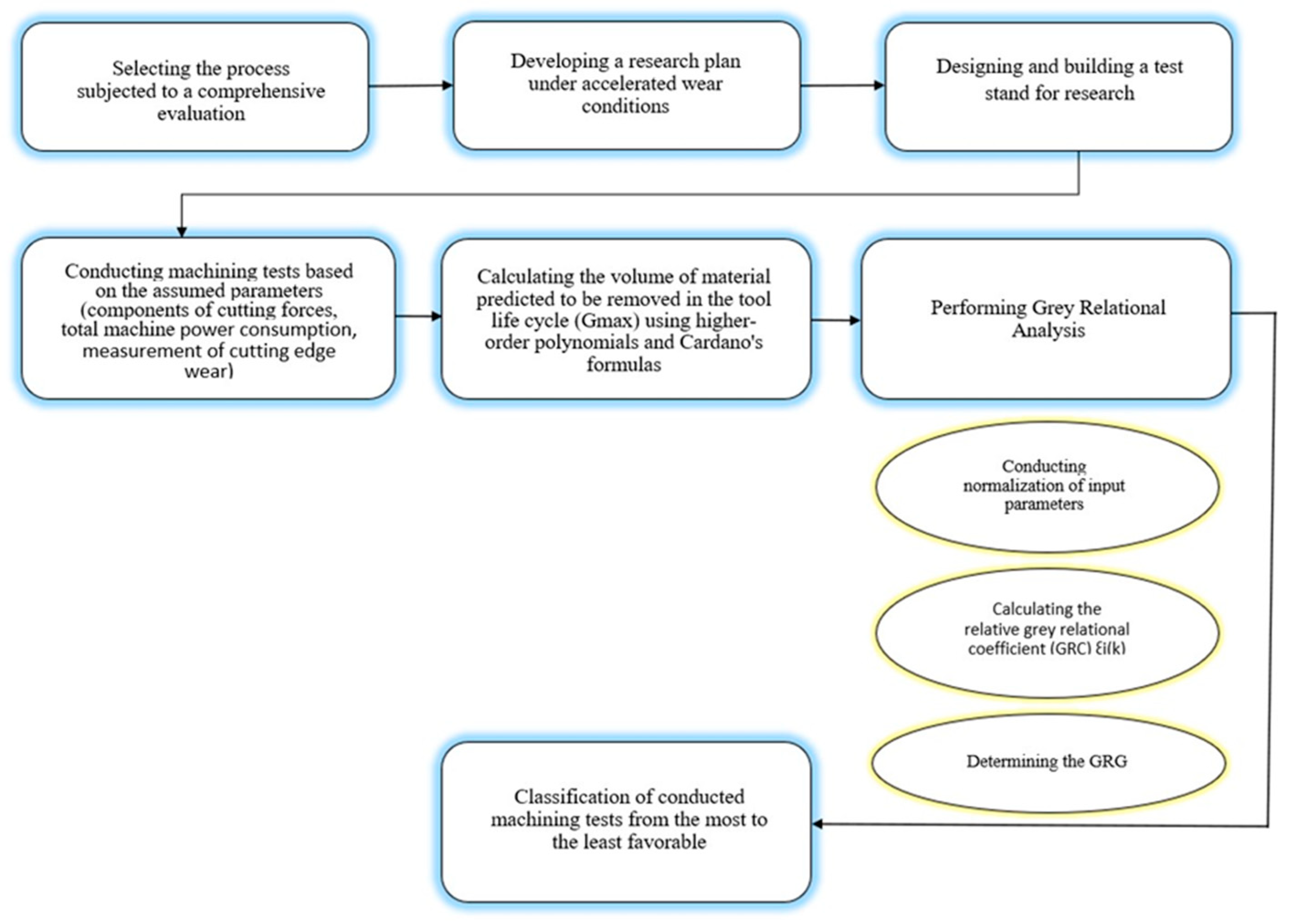
2. Materials and Methods

An attempt was made to develop a method for evaluating the high-performance milling of Inconel 718. This method should involve a comprehensive, multi-dimensional analysis of the process and allow for the comparison of various machining types, regardless of their kinematics or tool path. The primary assumptions of the proposed evaluation method are as follows:
  • the method pertains only to roughing operations;
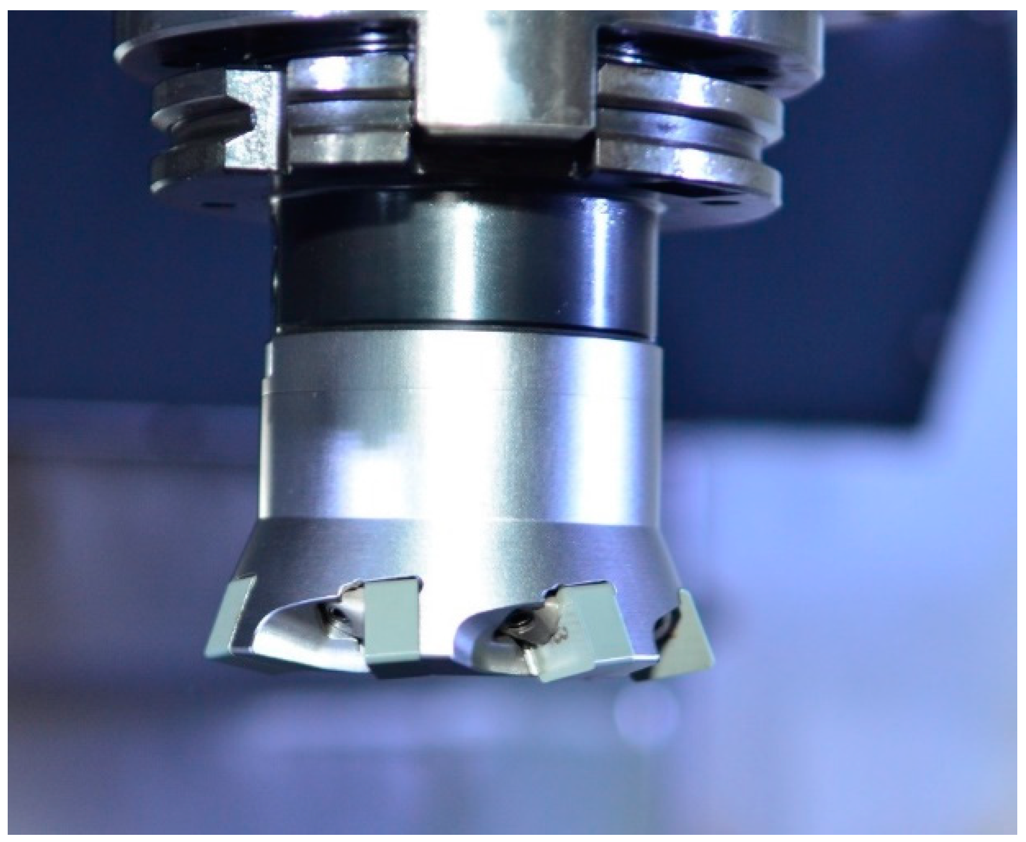
  • the compared processes must use tools with the same geometry (i.e., the same diameter and number of cutting edges, or in the case of assembled tools with interchangeable inserts, the same tool body or the same number of cutting edges in the tool);
  • the cutting speed must be the same in the compared processes;
  • the cutting trials must be conducted on the same machine tool;
  • The cutting trials must use material from the same heat of steel.
Additionally, the research plan must be designed to take place under accelerated wear conditions. Beyond the economic rationale, this approach allows for a more detailed analysis of a greater number of parameters. Based on studies [34] regarding minimum quantity lubrication (MQL) and other lubrication methods, it has been established that even minimal lubrication affects tool life in the milling process of Inconel alloys. For this reason, to accelerate tool wear, dry machining was chosen, allowing for the achievement of results related to accelerated wear. A key aspect of the method is to observe the accelerated wear mechanism in order to accurately calculate tool life until the VBBmax wear is reached.
Based on the literature analysis presented in the introduction, it was assumed that a comprehensive evaluation of the high-performance milling of Inconel 718 requires the investigation of the following process parameters:
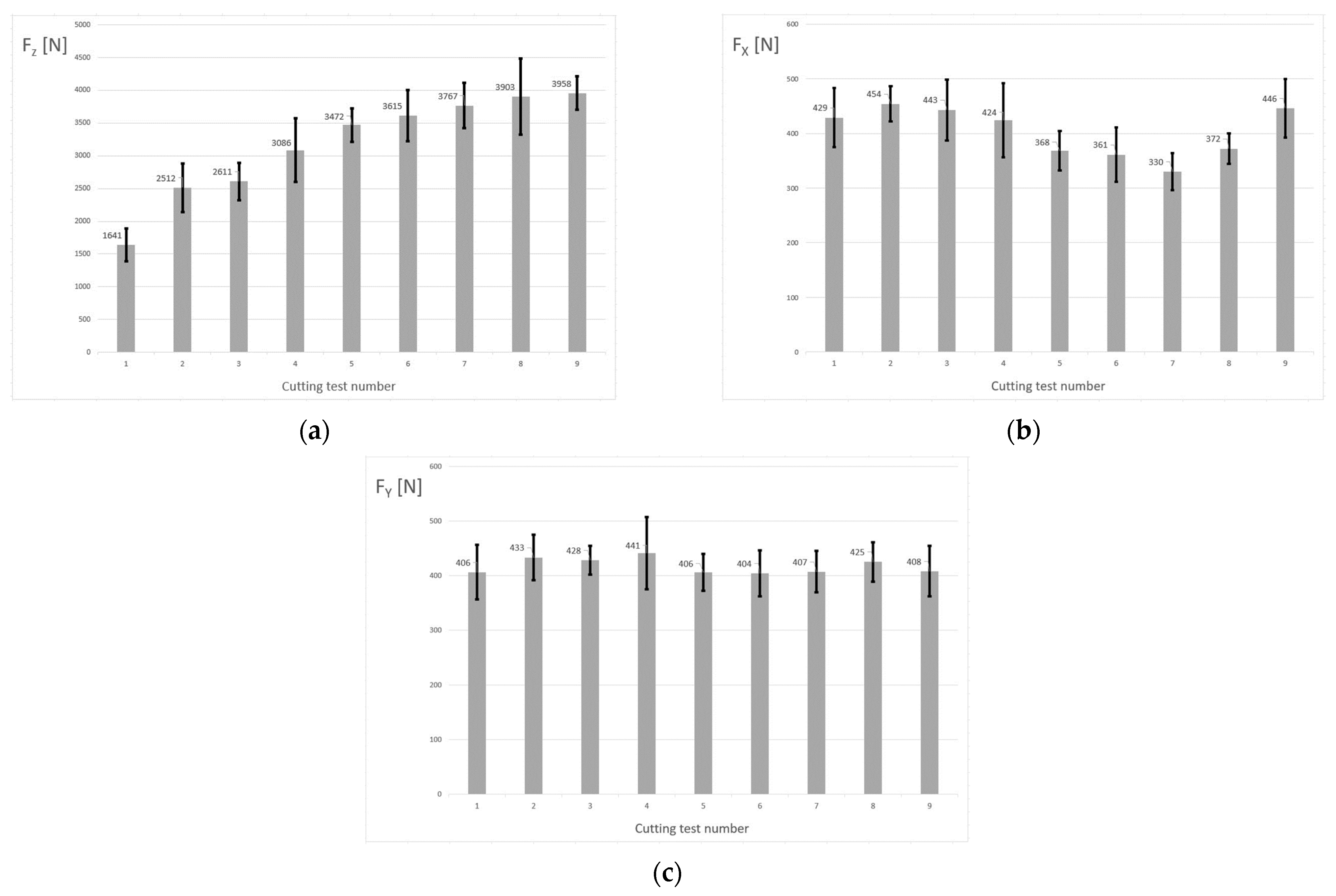
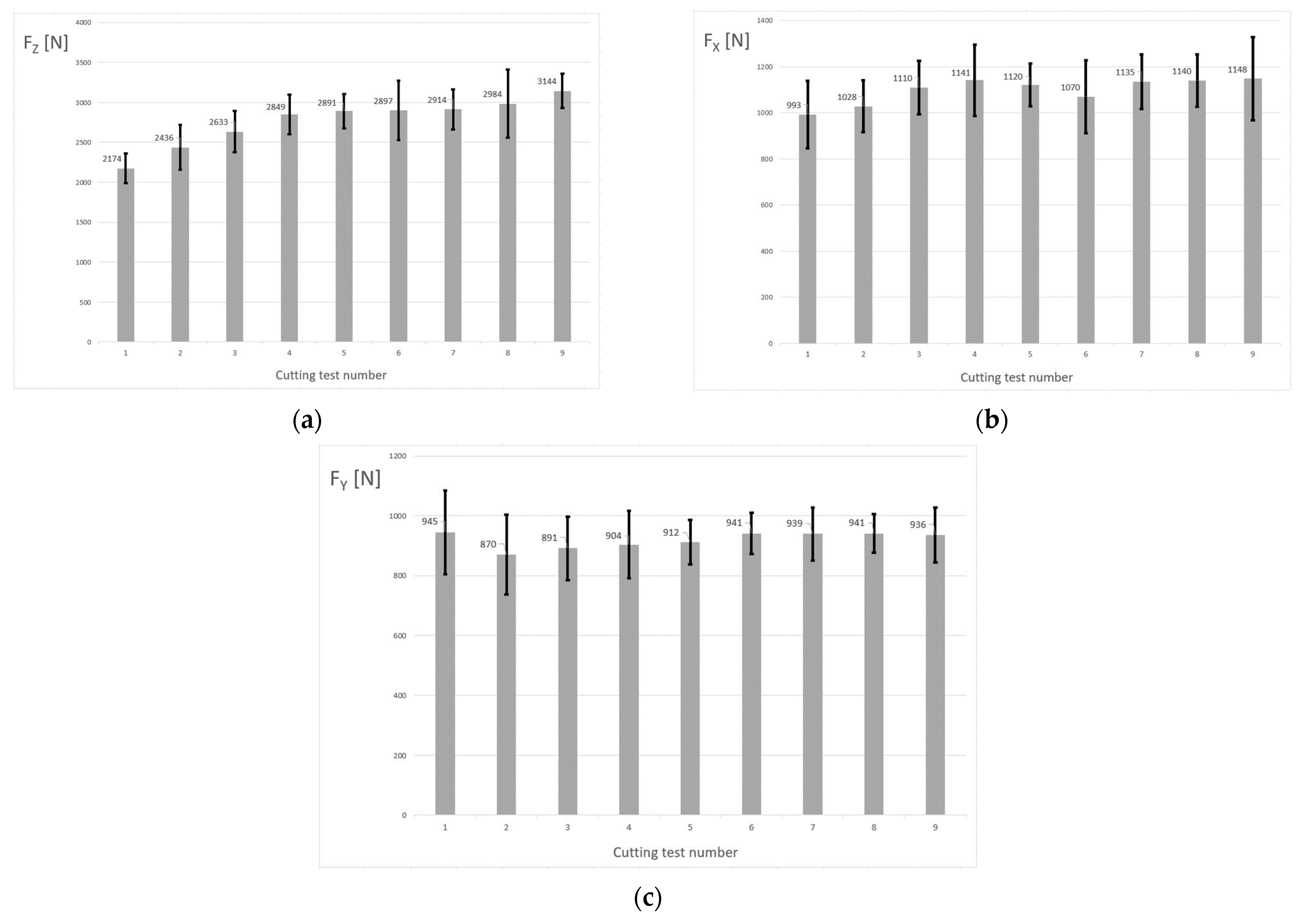
  • components of cutting forces Fx, Fy, and Fz [N];
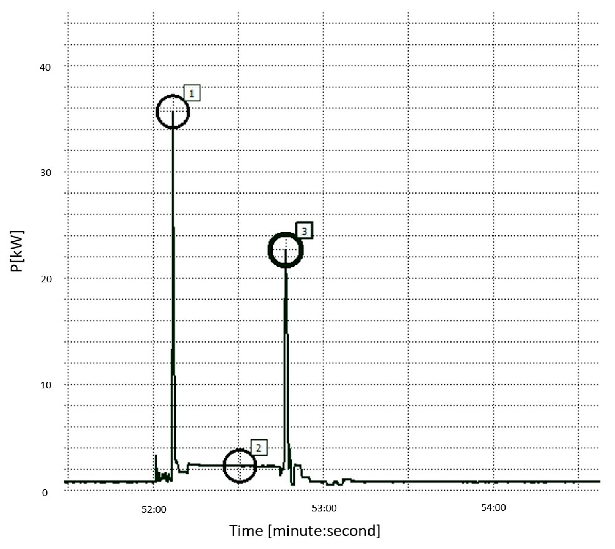
  • total machine power consumption (Pc) [kW];
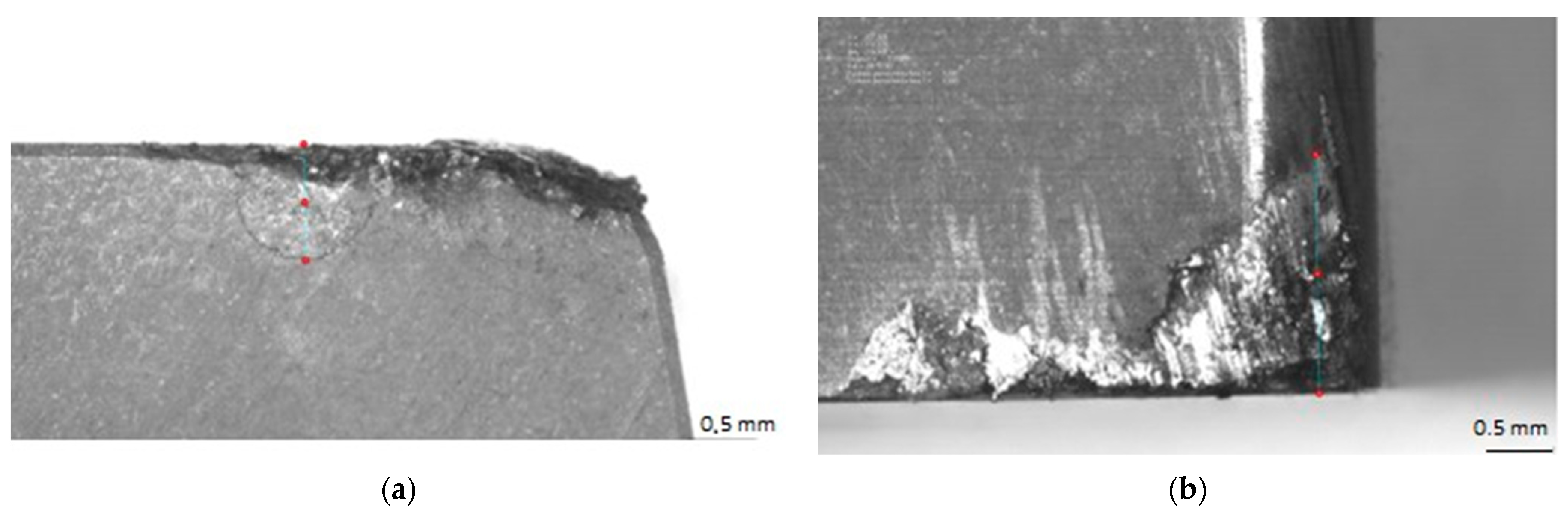
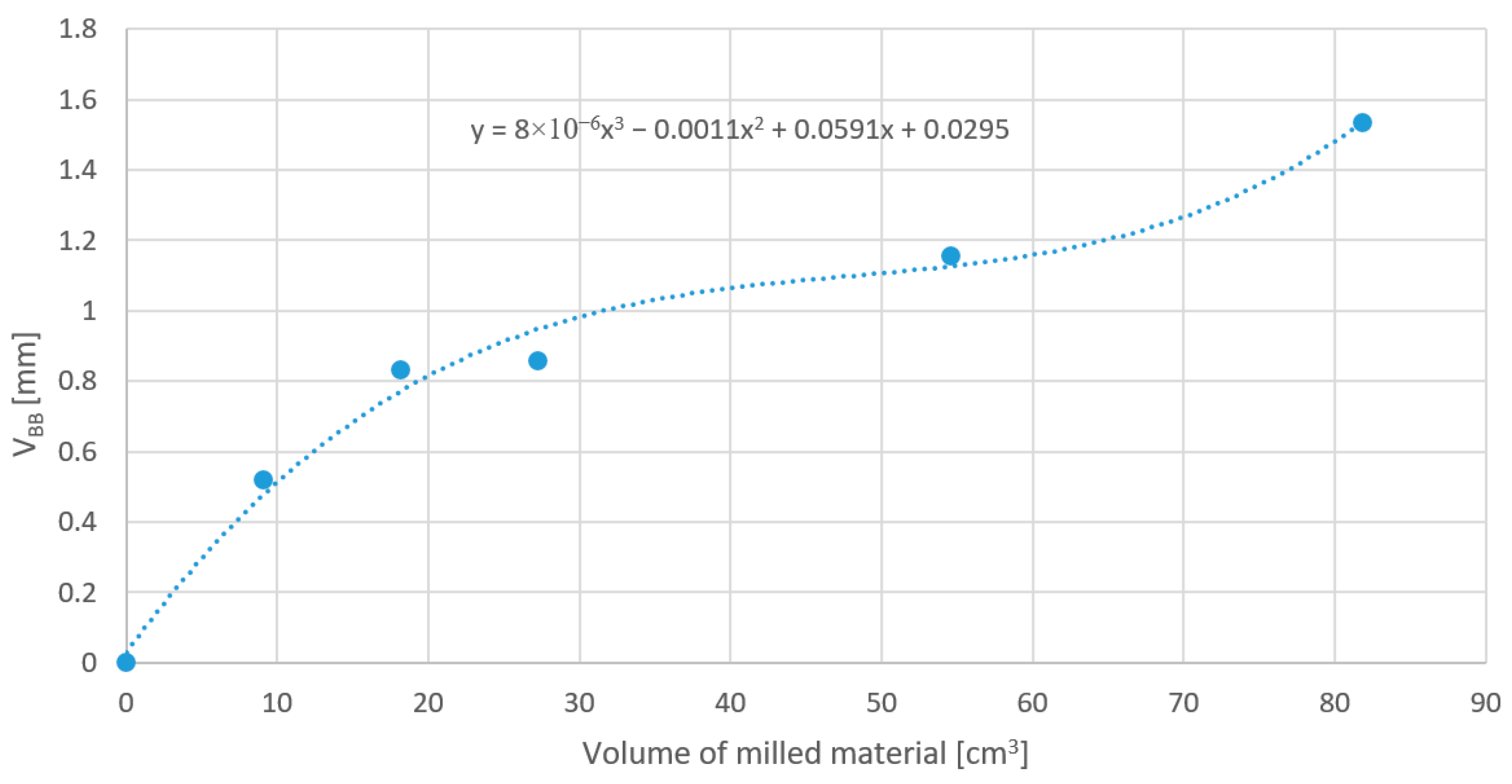
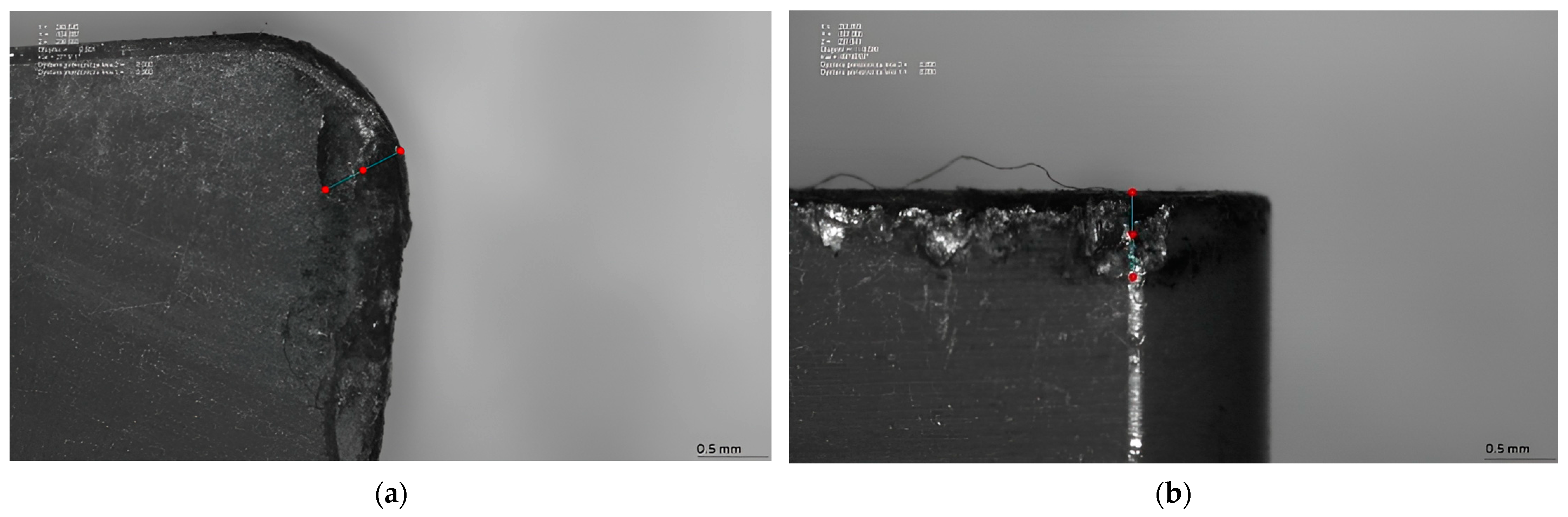
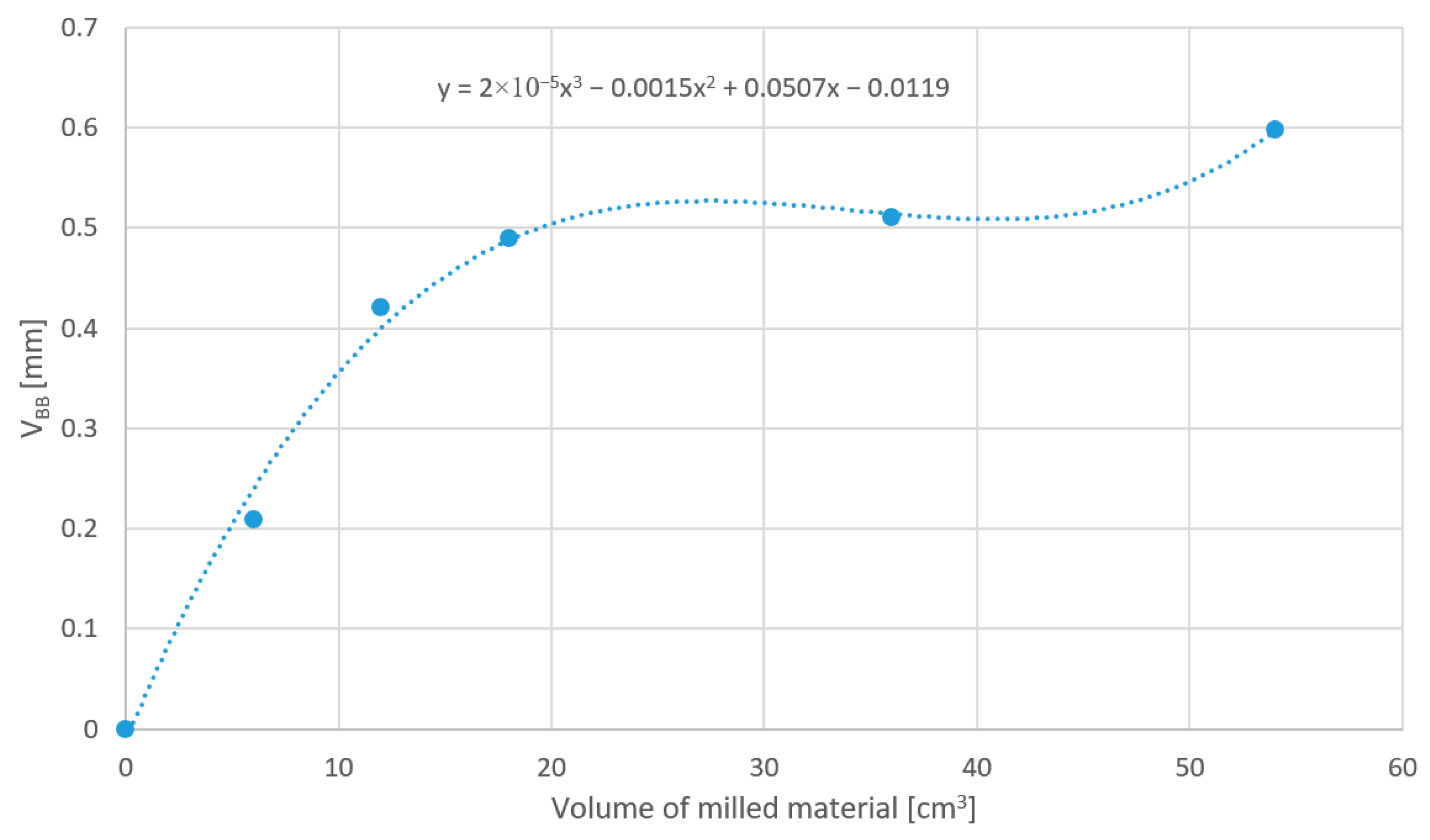
  • cutting-edge wear (VBB) [mm];
  • material removal rate (Q) [cm3/min].
Since the focus is on roughing operations, parameters related to the dimensional and shape accuracy of the machined surface and the residual stresses, as described in the literature, were excluded from the analysis.
To determine the values of the cutting forces, it is necessary to analyze the graphs of the force components to identify the dominant force component, which will reflect the increase in cutting resistance as tool wear progresses. Based on this component, the maximum value occurring during the cutting process should be determined, excluding the forces present during tool entry and exit from the material, as these may be prone to significant measurement errors.
Similarly, the total machine power consumption should be measured. Special attention should be paid to the spikes in the power values during the activation of various drives (particularly the main spindle drive), as these could mislead the person conducting the analysis. The values considered for the comparative evaluation method should be obtained during the cutting process, excluding the moments of tool entry and exit from the material.
Tool wear measurement is typically performed outside of the machine involved in the experiment. This means that the number of machining passes, as a function of the volume of machined material, must be designed to ensure that the number of wear measurements allows for the determination of a wear curve approximating the theoretical accelerated wear curve. It is crucial that wear measurement points are captured in each of the three wear stages, namely initial wear, steady-state wear, and accelerated wear. The polynomial curve describing the wear progression will be determined using Cardano’s formulas. Ultimately, the function describing the tool wear progression will take the form (Equation (1)), where the value of VBBmax will be determined based on the manufacturer’s data. The issue of tool wear determination in the rough milling of Inconel alloys is more extensively discussed in the literature [35].
a x 3 + b x 2 + c x + d = V B B m a x
The material removal rate (MRR) will be determined by the ratio of the volume of the removed material to the cutting tool’s working time in the machined material.
Due to the lack of data in the literature regarding the determination of appropriate weights and the influence of individual analyzed parameters on the machining process, it was decided to use grey relational analysis (GRA) for the evaluation.
To obtain accurate results, the data must first be normalized to avoid comparing different units. This step is necessary because the variability of the characteristics will be analyzed. Each result is assigned values within the range from 0 to 1. This is a conversion method used to obtain data for further analysis (referred to as processed data). Depending on whether the analyzed value should be maximized or minimized, a different formula is applied. For parameters where the values should be minimized (e.g., Pc and Fz), Equation (2) is used, while for parameters where the values should be maximized (e.g., Q and Gmax), Equation (3) is applied.
x i * k = max   x i k x i ( k ) max   x i k m i n   x i ( k )
x i * k = x i ( k ) m i n   x i ( k ) max   x i k m i n   x i ( k )
where i = l, …, m; k = l, …, n, m is the number of experimental data points, and n is the number of responses; xi(k) represents the original sequence, xi*(k) represents the sequence after initial data processing, and max xi(k) denotes the maximum value of xi(k).
Next, the grey relational coefficient ξi(k) is calculated from the previously normalized values. The relationship between the actual and normalized measured values is determined using Equation (4).
ξ i k = m i n + ξ m a x 0 i k + ξ m a x
where ∆0i is calculated using Equation (5):
0 i = x 0 k x i ( k )
where ∆min is the smallest value of ∆0i (k), and ∆max is the largest value of ∆0i (k) among all the compared values. ξ is the distinguishing or identification coefficient, and its value ranges from 0 to 1. ξ is typically set to 0.5.
The next step is the analysis of the grey relational grade (GRG). This is a multi-output feature analysis based on grey relational assessment. The result of this analysis transforms multiple responses into a single numerical value. The GRG (γ) is calculated using Equation (6), and its value ranges between 0 and 1.
γ i = 1 n k = 1 n ξ i ( k )
where γi is the required grey relational grade for the i-th set of parameters, and n is the number of process responses. In this work, the responses are the volumetric material removal rate (Q), the volume of material predicted to be removed during the tool’s life cycle (Gmax), the average maximum power consumption (Pc), and the average maximum component of cutting forces (Fz).
Based on the values of the grey relational grade (GRG, γ), a summary can be developed that includes the most favorable parameter sets and machining methods for the rough milling of Inconel alloys. The algorithm for using the described method is presented in the flowchart (Figure 1).
In order to conduct the analysis using the above-described method, it is necessary to prepare a testing setup. The Inconel sample must be properly prepared to allow for trials using both plunge milling and high-feed milling. The input material for the tests was a bar made of Inconel 718 with a diameter of 152.4 mm (6 inches) and a length of 150 mm. To avoid the issues commonly encountered in the machining of Inconel 718, preliminary machining was carried out on a FANUC Robocut C600iA/5/AWF/Z400 wire EDM machine. Another important aspect was preparing the sample so that it could be mounted on the dynamometer. Figure 2a shows the shape of the Inconel 718 sample after wire EDM machining, while Figure 2b illustrates the technical drawing of the tooling necessary to mount the material in the dynamometer. The method of mounting the sample in our experiment is designed to ensure the highest possible stiffness of the machined component. As shown in the research [36], the stiffness of the Inconel 718 alloy part is crucial for the stability of the machining process and the minimization of vibrations, which directly affects the results obtained during milling.
The measurement of forces was crucial during the experiments. It allowed for the observation and evaluation of process stability and the impact of cutting-edge wear on the process. Forces were measured in three directions aligned with the machine’s main axes—X, Y, and Z—referred to as Fx, Fy, and Fz, respectively. An important aspect was the amplitude of the forces, as it indicated process stability. The larger the fluctuations, the less stable the process, and the more likely catastrophic tool wear would occur due to vibrations between the tool’s cutting edge and the workpiece material. The force measurement setup consisted of a Kistler piezoelectric dynamometer model 9199AA, a Kistler 5070A charge amplifier for Fx, Fy, and Fz forces, a Kistler 5697A data-acquisition device, and a laptop with DynoWare 2825D software for data analysis.
To measure energy consumption, a Sonel PQM-701 power quality analyzer was used to record real-time network parameters. This allowed for the recording of active and reactive power values at the set frequency. The power quality analyzer was connected to the HAAS VF3/YT milling center according to the diagram shown in Figure 3.
The measurements of cutting insert wear were carried out in the measurement laboratory. A ZEISS O-INSPECT 332 multisensory machine with a measurement range of 300 × 200 × 200 mm was used for the wear analysis of the inserts. This was a numerically controlled measurement device equipped with both a tactile scanning head and a ZEISS Discovery V12 measuring lens, operating like a microscope, with a field of view ranging from 1.3 × 1 mm2 to 16.1 × 12 mm2, depending on the magnification used. Measurements could be performed in both transmitted and reflected light. Full adjustment of the light intensity in two colors—blue and red—was available, allowing for contrast adjustments during reflected light measurements, regardless of the color and material of the measured part.
The tests were conducted on a HAAS VF3/YT milling center. This is a 4-axis machining center with a working area of 1016 × 660 × 635 mm. It was equipped with an SK50 tool holder system, which is dedicated to roughing operations. The machine was fitted with a spindle, delivering a maximum power of 22.4 kW. The tool used for the measurements was a custom-made milling head from Seco Tools. This tool provides a unique opportunity to compare two milling methods (plunge milling and high-feed milling) using a single tool, which has not been possible until now. Additionally, this milling head is not commercially available. It was designed in collaboration with a tooling company and is not yet available through standard commercial channels. Standardized CNGN120712 whisker-reinforced inserts (CW100) were used in the tool design. To reduce project and production costs, the clamping system was adapted so that additional central holes for screws were not required in the inserts for mounting them on the milling head. A clamping system similar to that used in turning systems was implemented. The clamping part was made according to the [38] using a 27 mm diameter shank holder. The milling head was fastened to the holder with an M12 hex screw. The tool, along with the holder, was mounted on the machine (Figure 4).
The main research plan involved the use of two methods for milling Inconel alloy, namely high-feed milling and plunge milling. A total of 63 machining passes were planned, with 9 machining passes for each of the 7 parameter sets, 4 of which were for high-feed milling and 3 for plunge milling. All tests were conducted at a cutting speed of 800 m/min. The primary goal of determining the cutting parameters for the experiment was to validate the evaluation method and assess whether it could detect significant differences in the cutting trials under various conditions of depth of cut, feed per tooth, and milling method. The parameters applied in the experiment were determined in consultation with Seco Tools, which was the company that produced the new milling head and initially verified the parameter range in which it could be used. Additionally, we referred to studies [12,39], which analyzed the milling parameters of Inconel alloy. The cutting parameters were also selected with consideration of the milling machine’s capabilities, particularly its maximum cutting power. The main research plan is presented in the table (Table 1).

3. Results and Discussion

3.1. High-Feed Milling

During high-feed milling, a significantly higher value of the Fz force component was observed compared to the Fx and Fy components. In Figure 5a, which shows the progression of the Fz force component during cutting, the force values increased as the cutting-edge wear progressed. In contrast, in Figure 5b,c, which depicts the progression of the Fy and Fx force components, the force values were independent of the cutting-edge wear. The differences in results between the subsequent trials can be attributed to measurement errors in the data-acquisition system, the dynamic nature of the process, and the short cutting-cycle time.
The machine power consumption during machining was read from the graph (Figure 6), which was characterized by the presence of three points, marked in the figure. The first point corresponds to the total instantaneous machine power consumption during the activation of the main spindle rotation. The second point represents the power consumption during the spindle rotation, just before the cutting process begins, and the third point corresponds to the maximum power consumption during cutting for the given trial. The value measured at the third point was used for analysis. In the example presented in the graph, it was 22.86 kW. Regardless of the parameters used, the shape of the graph remained the same, differing only in the maximum values reached.
According to the presented comprehensive evaluation method, the wear of the cutting edge was analyzed. After each machining pass, the cutting inserts were observed and measured under a microscope. Both the flank surface and rake face of the insert were inspected. During the observation of the cutting inserts under a microscope, it was noted that the wear of ceramic inserts followed the accelerated wear mechanism. In the initial phase, micro-cracks and chipping of the cutting edges appeared, which is characteristic of ceramic tools. Then, during the stable phase, wear mainly occurred through uniform abrasion of the flank and rake surfaces. In the final phase, the wear mechanism accelerated rapidly, leading to significant chipping and the breaking away of fragments from the cutting edges of the tools. Figure 7 shows the cutting insert after completing the ninth machining pass with the following parameters: vc = 800 m/min, fz = 0.4 mm/tooth, ae = 100% of the tool diameter (70.54 mm in this case), and ap = 0.5 mm. On the rake face, chipping was observed, reaching a value of up to 0.85 mm. This distance was measured by drawing a line perpendicular to the cutting edge. No micro-chipping was found on the cutting edge itself, but on the flank face, abrasive wear of up to 1.76 mm was observed.
Based on the measurement of cutting-edge wear, the volume of material predicted to be removed during the tool’s life cycle (Gmax) was calculated, taking into account the maximum allowable cutting-edge wear value (VBBmax) of 3.5 mm, as specified by the manufacturer. The extrapolated volume of material that could be removed before reaching the cutting-edge wear limit was determined to be 106.39 cm3. Figure 8 shows the graph of VBB wear measured as a function of the volume of machined material, along with the trend line determined by a third-degree polynomial. The data for the graph are presented in Table 2.
In analyzing the relationships, a summary table (Table 3) was compiled with the parameters used for further analysis. The following factors were considered: the volumetric material removal rate (Q), the average maximum power consumption, the volume of material predicted to be removed during the tool’s life cycle (Gmax), and the average maximum cutting-force component (Fz).

3.2. Plunge Milling

During plunge milling, a higher value of the Fz force component was observed compared to the Fx and Fy components. However, this difference was smaller than in the case of high-feed milling. In Figure 9a, which shows the progression of the Fz force component during cutting, the force values increased as the cutting-edge wear progressed, but this occurred less dynamically compared to high-feed milling. The Fz force values increased in a manner closer to linear. In Figure 9b,c, which shows the progression of the Fx and Fy force components, the force values were independent of cutting-edge wear, but the values were higher than those observed in high-feed milling. The differences in results between trials can be attributed to measurement errors in the data-acquisition system, the dynamic nature of the process, and the short cutting-cycle time.
Similar to high-feed milling, an analysis of cutting insert wear on both the rake face and flank face was conducted (Figure 10). The wear mechanism in plunge milling followed the same accelerated wear pattern as observed in high-feed milling. Micro-chipping was observed on the rake face, and the abrasive wear reached a value of up to 0.6 mm. This distance was measured by drawing a line perpendicular to the cutting edge. Micro-chipping was also found on the cutting edge itself, while abrasive wear on the flank face was observed, also reaching up to 0.6 mm.
Based on the cutting-edge wear measurements, the volume of material predicted to be removed during the tool’s life cycle (Gmax) was calculated. The extrapolated volume of material that could be removed before reaching the cutting-edge wear limit was determined. Figure 11 shows the graph of VBB wear measured as a function of the volume of machined material, along with the trend line determined by a third-degree polynomial. In both high-feed milling and plunge milling of Inconel alloy, an initial phase of accelerated tool wear was observed during machining. The data for the graph are presented in Table 4.
When analyzing the relationships, a summary table (Table 5) was compiled with the parameters used for further analysis. Similar to high-feed milling, the following factors were considered: the volumetric material removal rate (Q), the average maximum power consumption, the volume of material predicted to be removed during the tool’s life cycle (Gmax), and the average maximum cutting-force component (Fz).

3.3. Evaluation Method Results

The values of the four parameters analyzed in this evaluation method were calculated according to the presented methodology. First, the normalized indicators of the summary results were computed (Table 6).
Based on the normalized indicators, the grey relational coefficients (GRC) were calculated (Table 7).
In the final step, the grey relational grade (GRG) was determined. The parameter sets were ranked from best to worst according to the evaluation method. The summary results of the analysis are presented in the table (Table 8).
The main objective of this article was to develop, present, and verify a comprehensive evaluation method for the high-performance milling of Inconel 718, based on an experiment conducted under accelerated wear conditions. The experiment examined parameters such as the distribution of cutting-force components, total machine power consumption, cutting-edge wear, and material removal rate. The developed method allows for the classification of the applied machining methods and process parameters from the most to the least favorable, in accordance with the established process boundary conditions. The experimental studies and verification of the evaluation method demonstrated its usefulness for assessing machining processes based on different process kinematics. By conducting the experiment under accelerated wear conditions, it is possible to determine an extrapolated value of the material volume likely to be removed during the tool’s life cycle. It is also worth noting that the presented evaluation method can be applied to other types of hard-to-machine materials. Furthermore, it can be expanded to include additional factors, such as vibration measurement or temperature in the cutting zone, depending on specific needs.
An additional goal of this article was to compare the machining capabilities of Inconel 718 using two different machining methods, namely high-feed milling and plunge milling. Currently, there are no milling heads on the market with a low approach angle that allow for both plunge milling and high-feed milling. The milling head used to verify the evaluation method was custom-made. The evaluation results indicate that plunge milling using a low approach angle can be competitive compared to other rough milling methods for Inconel 718. Although four out of the top five results were achieved with the high-feed milling method, one set of plunge milling parameters ranked second among all machining trials. It is worth noting that the greatest advantage of this type of machining is the lower maximum Fz force component during the cutting process. As indicated by the literature studies [40], reducing the value of this force can significantly impact the accuracy of the machine tool during its operation. In the conducted studies, the maximum Fz force component for plunge milling was 25% lower than for high-feed milling. However, this did not result in a lower average power consumption across all machining cycles.
Based on the obtained results, it can be observed that the depth of cut (ap), feed per tooth (fz), and milling type have a significant impact on energy consumption, tool wear, and cutting forces. As the depth of cut increases, both energy consumption and cutting forces rise, as greater depth requires more power to remove the material. For example, in high-feed milling, increasing the depth of cut from 0.5 mm to 1 mm leads to an approximately 30% increase in the average maximum power consumption. A higher feed per tooth results in greater energy consumption and increased cutting forces due to the larger amount of material being removed, while only slightly influencing the volume of material removed by the tool during its work cycle. In both high-feed milling and plunge milling, higher feed rates cause a significant increase in axial forces (Fz), which directly affects the energy consumption of the machining process. Comparing the two milling methods, high-feed milling generally consumes more energy and leads to faster tool wear due to higher cutting forces and the larger volume of material being removed. On the other hand, plunge milling, though slower in terms of material removal, is characterized by lower cutting forces and reduced energy consumption, which can prolong tool life and reduce vibrations. In summary, increasing both the depth of cut and feed per tooth leads to higher energy consumption, faster tool wear, and greater cutting forces, with high-feed milling being more efficient for material removal but more demanding in terms of energy consumption and tool durability compared to plunge milling.

4. Conclusions

The article presents a comprehensive evaluation method for the high-performance milling of Inconel 718 alloy, which takes into account key process parameters, such as cutting forces, tool wear, machine power consumption, and material removal rate. Based on the research, it can be concluded that:
  • The method has been verified for two different Inconel milling processes, allowing for the assessment of its effectiveness and applicability in real machining conditions;
  • The research results showed that high-feed milling ensures higher material removal rates and lower tool wear, making it more efficient for roughing operations;
  • Plunge milling was characterized by a lower axial force component (Fz), which can positively influence machining accuracy and process stability;
  • The use of accelerated tool wear allows for a detailed analysis and comparison of different milling techniques and tools used in the machining process;
  • Appropriate cutting parameters, such as spindle speed, feed rate, and depth of cut, significantly affect tool life and the quality of the machined surface;
  • The proposed evaluation method is universal and can also be applied to other hard-to-machine materials, not just Inconel alloys;
  • Optimization of process parameters, such as cutting forces and power consumption, is crucial for increasing efficiency and reducing the machining costs of high-strength alloys like Inconel 718;
  • The optimal machining method, according to the assumptions of the verified evaluation method, was high-feed milling with the parameters: vc = 800 m/min, fz = 0.3 mm/tooth, ae = 100% of the tool diameter (72.8 mm), and ap = 1 mm, which is consistent with the results found in the literature [12,39].
The developed method not only allows for the analysis of a greater number of parameters simultaneously but also takes into account the aspect of energy consumption, which has not been widely studied in the literature so far. Furthermore, the use of a custom-designed tool enabled the comparison of two milling methods, which represents an innovative element in the context of the previous research on milling Inconel 718.

Author Contributions

Conceptualization, W.B. and W.S.; methodology, P.P. and W.B.; software, W.B.; validation, W.S.; formal analysis, P.P.; investigation, P.P. and W.B.; resources, P.P. and W.B.; data curation, W.B.; writing—original draft preparation, P.P. and W.B.; writing—review and editing, P.P. and W.S.; visualization, P.P. and W.B.; supervision, W.S.; project administration, P.P.; funding acquisition, P.P. All authors have read and agreed to the published version of the manuscript.

Funding

The research was funded by the statutory grant of the Department of Machine Tools and Mechanical Technologies at Wroclaw University of Science and Technology and from the funds of the pro-quality subsidy for the development of the research potential of the Faculty of Mechanical Engineering of Wroclaw University of Science and Technology in 2024 (number 8211204601). The APC was funded from the funds of the pro-quality subsidy for the development of the research potential of the Faculty of Mechanical Engineering of Wroclaw University of Science and Technology in 2024.

Institutional Review Board Statement

Not applicable.

Informed Consent Statement

Not applicable.

Data Availability Statement

The raw data supporting the conclusions of this article will be made available by the authors upon request.

Acknowledgments

The authors would like to thank Zakład Mechaniki Maszyn Borkowscy Sp. J. for their assistance in conducting the cutting tests and Seco Tools for manufacturing the custom-designed milling head used in the research.

Conflicts of Interest

The author declares no conflicts of interest.

References

  1. Choudhury, I.A.; El-Baradie, M.A. Machinability of Nickel-Base Super Alloys: A General Review. J. Mater. Process. Technol. 1998, 77, 278–284. [Google Scholar] [CrossRef]
  2. Khanna, N.; Agrawal, C.; Dogra, M.; Pruncu, C.I. Evaluation of Tool Wear, Energy Consumption, and Surface Roughness During Turning of Inconel 718 Using Sustainable Machining Technique. J. Mater. Res. Technol. 2020, 9, 5794–5804. [Google Scholar] [CrossRef]
  3. Singh, T.; Dureja, J.S.; Dogra, M.; Bhatti, M.S. Environment Friendly Machining of Inconel 625 under Nano-Fluid Minimum Quantity Lubrication (NMQL). Int. J. Precis. Eng. Manuf. 2018, 19, 1689–1697. [Google Scholar] [CrossRef]
  4. Hsiao, T.-C.; Vu, N.-C.; Tsai, M.-C.; Dang, X.-P.; Huang, S.-C. Modeling and Optimization of Machining Parameters in Milling of Inconel 800 Super Alloy Considering Energy, Productivity, and Quality Using Nanoparticle Suspended Lubrication. Meas. Control 2021, 54, 880–894. [Google Scholar] [CrossRef]
  5. Suárez, A.; Veiga, F.; Polvorosa, R.; Artaza, T.; Holmberg, J.; López de Lacalle, L.N.; Wretland, A. Surface integrity and fatigue of non-conventional machined Alloy 718. J. Manuf. Process. 2019, 48, 44–50. [Google Scholar] [CrossRef]
  6. Fernández-Lucio, P.; Pereira Neto, O.; Gómez-Escudero, G.; Amigo Fuertes, F.J.; Fernández Valdivielso, A.; López de Lacalle Marcaide, L.N. Roughing Milling with Ceramic Tools in Comparison with Sintered Carbide on Nickel-Based Alloys. Coatings 2021, 11, 734. [Google Scholar] [CrossRef]
  7. Zimmermann, R.; Welling, D.; Venek, T.; Ganser, P.; Bergs, T. Tool Wear Progression of SiAlON Ceramic End Mills in Five-Axis High-Feed Rough Machining of an Inconel 718 BLISK. Procedia CIRP 2021, 101, 13–16. [Google Scholar] [CrossRef]
  8. Holmberg, J.; Wretland, A.; Berglund, J.; Beno, T. A Detailed Investigation of Residual Stresses After Milling Inconel 718 Using Typical Production Parameters for Assessment of Affected Depth. Mater. Today Commun. 2020, 24, 100958. [Google Scholar] [CrossRef]
  9. Wu, X.; Zhu, W.; Chen, J. Tool Wear Mechanisms in Laser-Assisted Milling of Nickel-Based Superalloys. J. Braz. Soc. Mech. Sci. Eng. 2021, 43, 151. [Google Scholar] [CrossRef]
  10. Vasudevan, H.; Rajguru, R.; Dave, G.; Alva, A.; Punjani, V.; Bhurke, D. Experimental Investigation and Optimization of End-Milling Parameters in the Machining of Inconel 825 Using Carbide-Coated Tool. In Proceedings of International Conference on Intelligent Manufacturing and Automation; Springer: Singapore, 2019; pp. 401–412. [Google Scholar] [CrossRef]
  11. Altin, A.; Nalbant, M.; Taskesen, A. The Effects of Cutting Speed on Tool Wear and Tool Life When Machining Inconel 718 with Ceramic Tools. Mater. Des. 2007, 28, 2518–2522. [Google Scholar] [CrossRef]
  12. Molaiekiya, F.; Aliakbari Khoei, A.; Aramesh, M.; Veldhuis, S.C. Machined surface integrity of inconel 718 in high-speed dry milling using SiAlON ceramic tools. Int. J. Adv. Manuf. Technol. 2021, 112, 1941–1950. [Google Scholar] [CrossRef]
  13. Molaiekiya, F.; Stolf, P.; Paiva, J.M.; Bose, B.; Goldsmith, J.; Gey, C.; Engin, S.; Fox-Rabinovich, G.; Veldhuis, S.C. Influence of Process Parameters on the Cutting Performance of SiAlON Ceramic Tools During High-Speed Dry Face Milling of Hardened Inconel 718. Int. J. Adv. Manuf. Technol. 2019, 105, 1083–1098. [Google Scholar] [CrossRef]
  14. Saleem, M.Q.; Mumtaz, S. Face Milling of Inconel 625 via Wiper Inserts: Evaluation of Tool Life and Workpiece Surface Integrity. J. Manuf. Process. 2020, 56, 322–336. [Google Scholar] [CrossRef]
  15. Iç, Y.T.; Adıgüzel, Z.A.; Azizoğlu, A.B.; Keskin, A.E.; Köksal, M.; Özbek, B.S. Optimization of Machined Product Quality in the Milling Process of Inconel High-Tech Material. Prod. Manag. Process Control. 2023, 104, 71–79. [Google Scholar] [CrossRef]
  16. Zhang, H.-J.; Sun, C.; Liu, M.; Gao, F. Analysis of the Optimization of Tool Geometric Parameters for Milling of Inconel718. IOP Conference Series: Mater. Sci. Eng. 2018, 423, 012030. [Google Scholar] [CrossRef]
  17. Faraz, M.I.; Petru, J. Evaluation of Machining Variables on Machinability of Nickel Alloy Inconel 718 Using Coated Carbide Tools. Machines 2024, 12, 4. [Google Scholar] [CrossRef]
  18. Zhang, H.; Chen, F.; Li, Z.; Hu, W.; Sun, T.; Zhang, J. Investigation of Laser-Assisted Micro-Milling Process of Inconel 718. J. Manuf. Mater. Process. 2023, 7, 149. [Google Scholar] [CrossRef]
  19. Kim, E.J.; Lee, C.M. A Study on the Optimal Machining Parameters of the Induction Assisted Milling with Inconel 718. Materials 2019, 12, 233. [Google Scholar] [CrossRef] [PubMed]
  20. Finkeldei, I.; Stenzel, T.; Denkena, B. End milling of Inconel 718 using solid Si3N4 ceramic cutting tools. Procedia CIRP 2019, 81, 1131–1135. [Google Scholar] [CrossRef]
  21. Li, X.; Wang, Y.; Miao, L.; Zhang, W. Deformation Analysis of Continuous Milling of Inconel718 Nickel-Based Superalloy. Micromachines 2022, 13, 683. [Google Scholar] [CrossRef]
  22. Nalbant, M.; Altın, A.; Gökkaya, H. The Effect of Cutting Speed and Cutting Tool Geometry on Machinability Properties of Nickel-Base Inconel 718 Super Alloys. Mater. Des. 2007, 28, 1334–1338. [Google Scholar] [CrossRef]
  23. Zębala, W.; Gaweł, A. Additive and Subtractive Manufacturing of Inconel 718 Components–Estimation of Time, Costs and Carbon Dioxide Emission–Case Study. Adv. Sci. Technol. Res. J. 2024, 18, 98–109. [Google Scholar] [CrossRef] [PubMed]
  24. Thakur, A.; Gangopadhyay, S. State-of-the-Art in Surface Integrity in Machining of Nickel-Based Super Alloys. Int. J. Mach. Tools Manuf. 2016, 100, 25–54. [Google Scholar] [CrossRef]
  25. Mahesh, K.; Philip, J.T.; Joshi, S.N.; Kuriachen, B. Machinability of Inconel 718: A Critical Review on the Impact of Cutting Temperatures. Mater. Manuf. Process. 2021, 36, 753–791. [Google Scholar] [CrossRef]
  26. Pawade, R.S.; Joshi, S.S.; Brahmankar, P.K.; Rahman, M. An Investigation of Cutting Forces and Surface Damage in High-Speed Turning of Inconel 718. J. Mater. Process. Technol. 2007, 192–193, 139–146. [Google Scholar] [CrossRef]
  27. Amini, S.; Fatemi, M.H.; Atefi, R.K.H. High Speed Turning of Inconel 718 Using Ceramic and Carbide Cutting Tools. Arab. J. Sci. Eng. 2014, 39, 2271–2280. [Google Scholar] [CrossRef]
  28. Taşlıyan, A.; Acarer, M.; Şeker, U.; Gökkaya, H.; Demir, B. The Effect of Cutting Parameters on Cutting Force During the Processing of Inconel 718 Super Alloy. J. Fac. Eng. Archit. Gazi Univ. 2007, 22, 1–5. [Google Scholar]
  29. Thakur, D.G.; Ramamoorthy, B.; Vijayaraghavan, L. Machinability Investigation of Inconel 718 in High-Speed Turning. Int. J. Adv. Manuf. Technol. 2009, 45, 421–429. [Google Scholar] [CrossRef]
  30. Vinod, A.R.; Srinivasa, C.K.; Keshavamurthy, R.; Shashikumar, P.V. A Novel Technique for Reducing Lead-Time and Energy Consumption in Fabrication of Inconel-625 Parts by Laser-Based Metal Deposition Process. Rapid Prototyp. J. 2016, 22, 162–171. [Google Scholar] [CrossRef]
  31. Thirumalai, R.; Seenivasan, M.; Panneerselvam, K. Experimental Investigation and Multi Response Optimization of Turning Process Parameters for Inconel 718 Using TOPSIS Approach. Mater. Today Proc. 2020, 45, 467–472. [Google Scholar] [CrossRef]
  32. Sanghvi, N.; Vora, D.; Patel, J.; Malik, A. Optimization of End Milling of Inconel 825 with Coated Tool: A Mathematical Comparison Between GRA, TOPSIS and Fuzzy Logic Methods. Mater. Today Proc. 2020, 38, 2301–2309. [Google Scholar] [CrossRef]
  33. Karolczak, P.; Adamczak, M. Evaluation of the Influence of Tool Coatings on the Machinability of the Ti6Al4V Alloy Using Gray Relational Analysis. Adv. Sci. Technol. Res. J. 2024, 18, 13–28. [Google Scholar] [CrossRef] [PubMed]
  34. Pereira, O.; Urbikain, G.; Rodríguez, A.; Fernández-Valdivielso, A.; Calleja, A.; Ayesta, I.; López de Lacalle, L.N. Internal cryolubrication approach for Inconel 718 milling. Procedia Manuf. 2017, 13, 89–93. [Google Scholar] [CrossRef]
  35. Piórkowski, P.; Borkowski, W.; Bartoszuk, M.; Miko, E.; Skoczyński, W. Investigation of Cutting Tool Wear in the Milling Process of the Inconel 718 Alloy. Adv. Sci. Technol. Res. J. 2024, 18, 26–35. [Google Scholar] [CrossRef]
  36. Pérez-Ruiz, D.J.; Marin, F.; Martínez, S.; Lamikiz, A.; Urbikain, G.; López de Lacalle, L.N. Stiffening near-net-shape functional parts of Inconel 718 LPBF considering material anisotropy and subsequent machining issues. Mech. Syst. Signal Process. 2022, 168, 108675. [Google Scholar] [CrossRef]
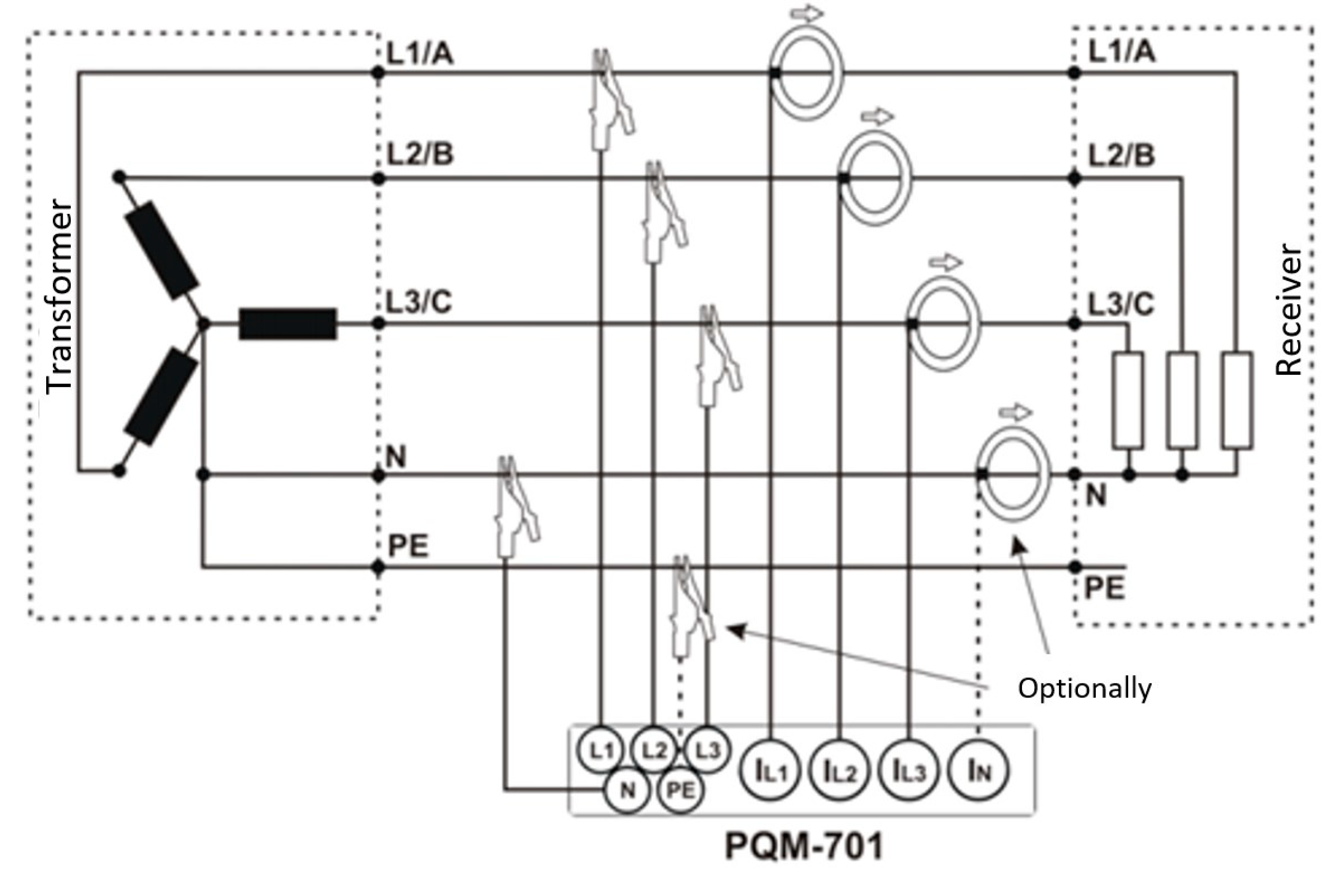
  37. PQM-701 Power Quality Analyser. User’s Manual. 2014, 22.
  38. ISO 13399-1:2006; Cutting tool data representation and exchange. Part 1: Overview, fundamental principles and general information model. ISO: Geneva, Switzerland, 2006.
  39. Osmond, L.; Cook, I.; Curtis, D.; Slatter, T. Tool Life and Wear Mechanisms of CVD Coated and Uncoated SiAlON Ceramic Milling Inserts When Machining Aged Inconel 718. Proc. Inst. Mech. Eng. Part B J. Eng. Manuf. 2024, 238, 1069–1083. [Google Scholar] [CrossRef]
  40. Jankowski, T.; Borkowski, W.; Piórkowski, P.; Roszkowski, A.; Skoczyński, W. Comparison of vertical milling centers geometric errors with different time of machining. Mechanik 2018, 91, 650–652. [Google Scholar] [CrossRef]
Figure 1. The flowchart of the algorithm implemented within the comprehensive evaluation method.
Applsci 14 09023 g001
Figure 2. (a) Test sample made from Inconel 718; (b) fixture for mounting the Inconel 718 sample on the dynamometer.
Applsci 14 09023 g002
Figure 3. Diagram of the Sonel PQM-701 analyzer connection to the wiring of the milling center [37].
Applsci 14 09023 g003
Figure 4. Designed milling head with CNGN120712 inserts, mounted in the spindle of the milling center.
Applsci 14 09023 g004
Figure 5. Relationship between the average maximum value of the (a) Fz; (b) Fx; and (c) Fy force components and subsequent test numbers for high-feed milling using CW100 inserts.
Applsci 14 09023 g005
Figure 6. Power consumption graph for a single pass of high-feed milling with the CW100 insert, with the following parameters: vc = 800 m/min, fz = 0.3 mm/tooth, ae = 70.54 mm, and ap = 0.5 mm.
Applsci 14 09023 g006
Figure 7. Microscope image of the (a) rake face and (b) flank face of the CW100 insert during high-feed milling (optical magnification ×1.6).
Applsci 14 09023 g007
Figure 8. Graph of cutting-edge wear (VBB) as a function of the volume of machined material for high-feed milling with the CW100 insert, with the following parameters: vc = 800 m/min, fz = 0.3 mm/tooth, ae = 72.8 mm, ap = 1 mm.
Applsci 14 09023 g008
Figure 9. Relationship between the average maximum value of the force component (a) Fz; (b) Fy; and (c) Fx and subsequent test numbers for plunge milling using the CW100 insert.
Applsci 14 09023 g009
Figure 10. Microscope image of the (a) rake face and (b) flank face of the CW100 insert during plunge milling.
Applsci 14 09023 g010
Figure 11. Graph of the relationship between cutting-edge wear (VBB) and the volume of machined material for plunge milling using the CW100 insert with the following parameters: vc = 800 m/min, fz = 0.08 mm/tooth, and ae = 3 mm.
Applsci 14 09023 g011
Table 1. Research plan.
Parameter SetMachining Typefz [mm/tooth]ae
[%D] or [mm]
ap [mm]Q [cm3/min]Theoretical Diameter D [mm]Spindle Speed n [rpm]Feed Rate vf [mm/min]
1High feed0.3100%0.5267.3970.5436107581
2High feed0.4100%0.5356.5270.54361010,108
3High feed0.5100%0.5445.6570.54361012,635
4High feed0.3100%1534.7872.834987346
5Plunging0.081-142.618031831783
6Plunging0.081.5 mm-213.918031831783
7Plunging0.083 mm-427.828031831783
Table 2. Data on cutting-edge wear (VBB) as a function of the volume of machined material for high-feed milling with the CW100 insert, with the following parameters: vc = 800 m/min, fz = 0.3 mm/tooth, ae = 72.8 mm, ap = 1 mm.
Volume of Milled Material [cm3]VBB [mm]
00
9.10.517
18.20.832
27.30.858
54.61.154
81.91.532
Table 3. Summary results for high-feed milling with the ceramic CW100 insert.
Parameter SetFeed per Tooth fz [mm/tooth]Width of Cut ae [%D]Depth of Cut ap [mm]Volumetric Material Removal Rate Q [cm3/min]Predicted Material Volume to be Removed in Tool Life Cycle Gmax [cm3]Average Maximum Power Consumption Pc [kW]Average Maximum Cutting-Force Component Fz [N]
10.370.540.5267.3957.3222.361935
20.470.540.5356.5254.04227.282524
30.570.540.5445.6557.8927.963174
40.372.81534.78106.3938.873096
Table 4. Data on the relationship between cutting-edge wear (VBB) and the volume of machined material for plunge milling using the CW100 insert with the following parameters: vc = 800 m/min, fz = 0.08 mm/tooth, and ae = 3 mm.
Volume of Milled Material [cm3]VBB [mm]
00
60.209
120.42
180.49
360.51
540.598
Table 5. Summary of plunge milling test results using the ceramic CW100 insert.
Parameter SetFeed per Tooth fz [mm/tooth]Width of Cut ae [%D]Depth of Cut ap [mm]Volumetric Material Removal Rate Q [cm3/min]Predicted Material Volume to be Removed in Tool Life Cycle Gmax [cm3]Average Maximum Power Consumption Pc [kW]Average Maximum Cutting-Force Component Fz [N]
50.08125142.6133.6115.412078
60.081.525213.9150.5821.912769
70.08325427.8273.1631.083638
Table 6. Normalized indicator values from the summary results of the main tests.
Parameter SetNormalized Volumetric Material Removal Rate Q
[-]
Normalized Volume of Material Predicted to be Removed in Tool Life Cycle Gmax [-]Normalized Average Maximum Power Consumption Pc
[-]
Normalized Average Maximum Cutting-Force Component Fz
[-]
10.3180.3260.7040.770
20.5450.2810.4941.000
30.7730.3340.4650.517
41.0001.0000.0000.547
50.0000.0001.0000.944
60.1820.2330.7230.675
70.7270.5430.3320.000
Table 7. Grey relational coefficient values—summary of the main test results.
Parameter SetGRC for Volumetric Material Removal Rate ξi(Q) [-]GRC for Volume of Material Predicted to be Removed in Tool Life Cycle ξi(Gmax) [-]GRC for Average Maximum Power Consumption
ξi(Pc)
[-]
GRC for Average Maximum Cutting-Force Component ξi(Fz) [-]
10.4230.4260.6280.685
20.5240.4100.4971.000
30.6880.4290.4830.509
41.0001.0000.3330.525
50.3330.3331.0000.900
60.3790.3950.6430.606
70.6470.5230.4280.430
Table 8. Results of the comprehensive evaluation method for high-performance milling of Inconel 718.
Parameter SetMachining Typefz
[mm/
tooth]
ae
[mm]
ap [mm]Q [cm3/min]Grey Relational Grade (GRG)Ranking Based on the Applied Evaluation Method
1High feed0.370.540.5267.390.5414
2High feed0.470.540.5356.520.6083
3High feed0.570.540.5445.650.5275
4High feed0.372.81534.780.7151
5Plunging0.08125142.610.6422
6Plunging0.081.525213.910.5067
7Plunging0.08325427.820.5076
Disclaimer/Publisher’s Note: The statements, opinions and data contained in all publications are solely those of the individual author(s) and contributor(s) and not of MDPI and/or the editor(s). MDPI and/or the editor(s) disclaim responsibility for any injury to people or property resulting from any ideas, methods, instructions or products referred to in the content.

