Article

Rock Fracturing Characteristics and Roadway Expansion Application of Static Crushing Agent under Multi-Row Drilling Condition

1
School of Energy Science and Engineering, Henan Polytechnic University, Jiaozuo 454000, China
2
School of Civil Engineering and Communication, North China University of Water Resources and Electric Power, Zhengzhou 450045, China
*
Author to whom correspondence should be addressed.
Appl. Sci. 2024, 14(19), 9032; https://doi.org/10.3390/app14199032 (registering DOI)
Submission received: 14 August 2024 / Revised: 25 September 2024 / Accepted: 30 September 2024 / Published: 6 October 2024
(This article belongs to the Special Issue Advanced Underground Coal Mining and Ground Control Technology)

Abstract

:
Static crushing agent (SCA) offers advantages such as good safety, no harmful gases, and minimal vibration, making SCA ideal for rock crushing in mines or underground engineering. To scientifically implement the section expansion of mine roadway, the rock mechanical parameters, SCA expansion properties, and cracking behavior of surrounding rock were investigated using laboratory tests, numerical simulations, and field experiments. Results indicate that the smaller hole spacing of SCA improves the fracturing effect on rock mass, reduces the required fracture initiation stress and penetration stress, and the presence of a free surface aids in fracture development in the rock mass. Optimal borehole design parameters and spacing distributions of the SCA were determined, and corresponding construction techniques of roadway expansion were proposed. Field tests demonstrate that static crushing technology, under multi-row drilling conditions, is highly effective for rock roadway expansion projects. These findings provide valuable guidance for non-explosive expansion and other roof breaking treatment projects.

1. Introduction

To ensure safe and efficient production in coal mines, it is necessary to widen the existing roadway cross-sections. Currently, there are mainly three methods for roadway cross-section expansion [1,2,3,4,5,6]: explosive blasting construction; pneumatic drilling and pick breaking; and breaking rock equipment construction. Although these technologies can solve the corresponding engineering problems, some issues still exist, such as high safety risks, low efficiency, restricted operational environments, and high labor intensity for workers. Static crushing agent (SCA) has the characteristics of no open flame, no vibration, stable performance, and easy operation, and it can maintain a large expansion force for a long time and is suitable for the requirements of the underground coal mine construction environment. Therefore, investigating a safe and efficient application method for SCA is significant to improving the efficiency of rock roadway expansion and reducing the labor intensity of workers.
Static crushing agent (SCA) is a gray-white powder mixture that is mixed with water in a certain proportion and filled into rock boreholes that need to be fractured. After a certain period of reaction, the expansion pressure within the hole can achieve the purpose of fracturing rock [7]. Scholars have conducted a lot of analyses on the SCA’s properties. Studies found the mixing water temperature does not affect the reached maximum temperature of the SCA’s hydration reaction; however, it does affect the reaction rate, and a higher mixing temperature results in a faster reaction rate of SCA [8,9,10]. Experiments with different water–cement ratios under the same mixing temperature and room temperature conditions have shown that the water–cement ratio significantly affects the volume expansion rate of SCA, which decreases at a certain extent as the water–cement ratio increases [9,11]. Tests have also found that the mixing water temperature has a significant impact on the reaction rate of the static crushing agent but has a smaller effect on the volume expansion rate of SCA, while the environmental temperature has a certain effect on the volume expansion rate of SCA and does not significantly affect the reaction rate [12]. Experiments indicate the water–cement ratio affects both the expansion pressure and the reaction rate; a higher water–cement ratio results in a slower reaction rate and produces lower expansion pressure [13]. Research on the composition proportion of SCA has found that the proportion of CaO, bentonite, and cement affects the expansion pressure of SCA, so different types and proportions of SCA have different expansion effects [14]. Because the reaction process of SCA is relatively mild, there exists many advantages for rock fracturing, such as no open flame, no dust, no explosive shock, no flying stones, and no noise. Currently, SCA has been widely applied in demolition projects of ground concrete, rock structures, and buildings [15].
The drilling depth, hole diameter, and hole spacing of SCA application are key parameters that affect the fracturing effect of the static cracking agent. Xu et al. [16] have shown that the greater the hole depth, the better the fracturing effect, but the drilling depth should not be too large, generally controlled between 1.5 and 1.8 m. Nan and Feng et al. [17,18] found that a larger hole diameter produces greater expansion stress; however, if the hole diameter is too large, it may lead to blowouts. Due to varying rock hardness, different required fracturing stresses exist. The selection of borehole spacing can significantly influence the fracturing effect of the static cracking agent, smaller spacing yields better fracturing results, while larger spacing yields poorer results [19,20,21]. Generally, the application of SCA in coal mines still requires further research. In rock fracture projects, the use of explosives is restricted, and breaking hard rocks using machine equipment is also difficult. Therefore, investigating coal-rock fracture mechanisms and the application technology of SCA is significant to improving the safety and efficiency of mine production.
In this paper, a static crushing technology is adopted in the roadway expansion of a mine. To obtain an efficient construction effect of roadway expansion, the static cracking mechanism of rock roadway expansion is investigated using laboratory tests and numerical simulations. Firstly, the mechanical parameters of roadway surrounding rock are obtained by the rock mechanical experiment, then the expansion properties of SCA were tested, and the cracking process of surrounding rock by SCA was also characterized. Further, a method of using static crushing agent (SCA) to fracture roadway surrounding rock is conducted at the engineering site for a roadway expansion project, the charge amount of SCA, the hole spacing, and the construction process are determined, and the construction effect of roadway expansion are discussed.

2. Performance Testing of SCA and Rock Material

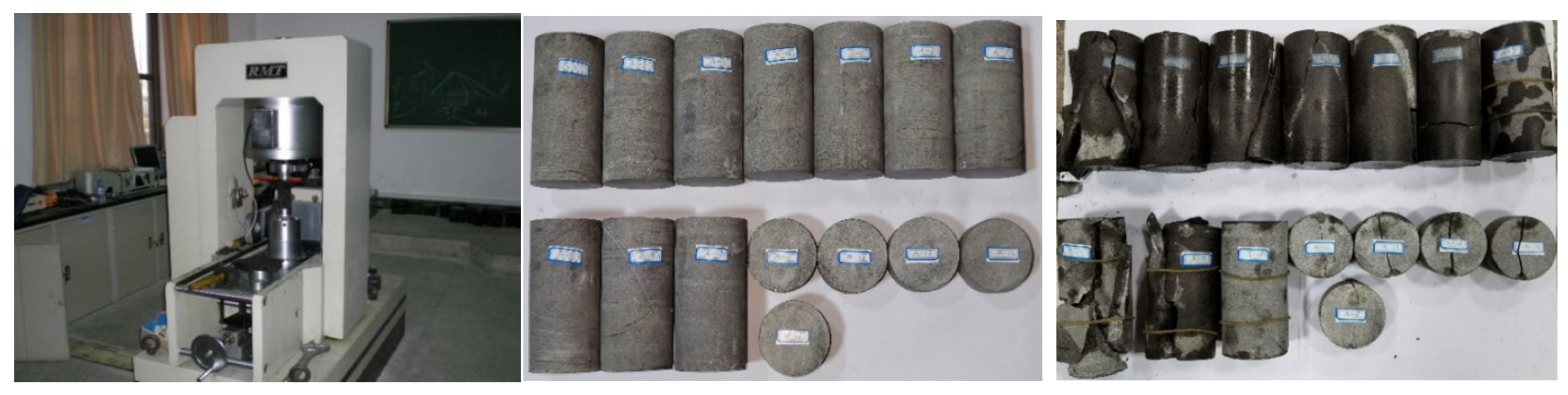
2.1. Performance Testing of Rock Sample

In the roadway expansion project, the surrounding rock type of the mine roadway is sandstone, and the standard rock specimens were prepared from on-site samples. To obtain the properties of roadway surrounding rock, the mechanical parameters of the rock specimen are tested using an RMT150 rigid pressure-testing machine. The triaxial, uniaxial compression tests, and Brazilian tensile test are conducted based on the regulation for testing the physical and mechanical properties of rock [22]. In the experiment, the testing equipment, rock specimen, and rock failure results are shown in Figure 1.
Based on the experiment test, the mechanical parameters of the roadway surrounding rock are obtained, as shown in Table 1.

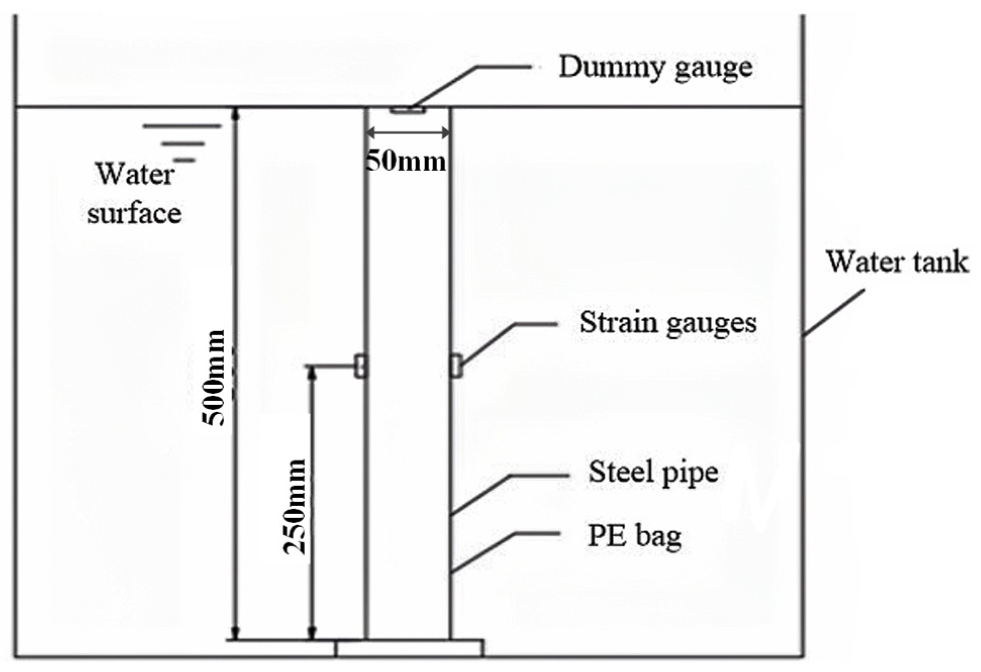
2.2. Performance Testing of SCA

The properties of static crushing agent (SCA) are mainly influenced by factors such as material ratio, mixing water temperature, ambient temperature, and water–cement ratio. Due to constraints in underground coal mine conditions, field tests often focus on the water–cement ratio of the ready-made SCA. In this section, to guide the on-site construction of the roadway expansion project, the expansion characteristics of SCA with different water–cement ratios were obtained by experiment tests based on the standard of “Soundless Crushing Agent: JC506-2008” [23]; the test schematic of SCA expansion force is shown in Figure 2.
The expansion stress of SCA is measured by the resistance strain gauge method, and a constant temperature water bath is used to obtain the expansion stress–time curve at the underground temperature. The expansion stress is calculated using Equation (1) [23]:
P = E s · K 2 1 ε θ 2 ν
where P represents the expansion stress (MPa); Es is the elastic modulus of Q235 steel pipe, which is 206 GPa; K is the ratio of the steel pipe’s outer diameter to inner diameter (mm); εθ is the circumferential strain of the steel pipe; and ν is the Poisson’s ratio, taken as 0.3.
Based on experiment tests, the time–history curves of expansion stress of SCA with different water–cement ratios are shown in Figure 3. From Figure 3, the expansion stress of SCA increases at a faster rate within 0–30 h. After 30 h, the expansion stress continues to rise with the growth of reaction time, but the rate of increase gradually decreases and eventually levels off. Comparing the expansion stresses of SCA with water–cement ratios of 0.26, 0.3, 0.34, and 0.38, when the water–cement ratio is 0.3, the SCA slurry has the fastest rate of increase in expansion stress and reaches the highest value (75.9 MPa) after trending toward stability. This means that SCA at a water–cement ratio of 0.3 has the highest expansion stress, resulting in a more pronounced fracturing effect.

3. Simulation on Rock Fracturing Characteristics

The expansion tests indicate that the static crushing agent (SCA) can maintain a high expansion stress over a long period. Based on this characteristic, roadway expansion can be achieved by increasing the SCA borehole number according to the actual underground drilling time. To achieve the desired effect of roadway expansion, the SCA drilling parameters need to be optimized. For different types of rocks, the required fracturing stress differs, and different hole spacing greatly affects the fracturing effect of SCA. By using Abaqus simulation software [24,25], this paper mainly studies the fracturing effect of SCA under different hole spacings.

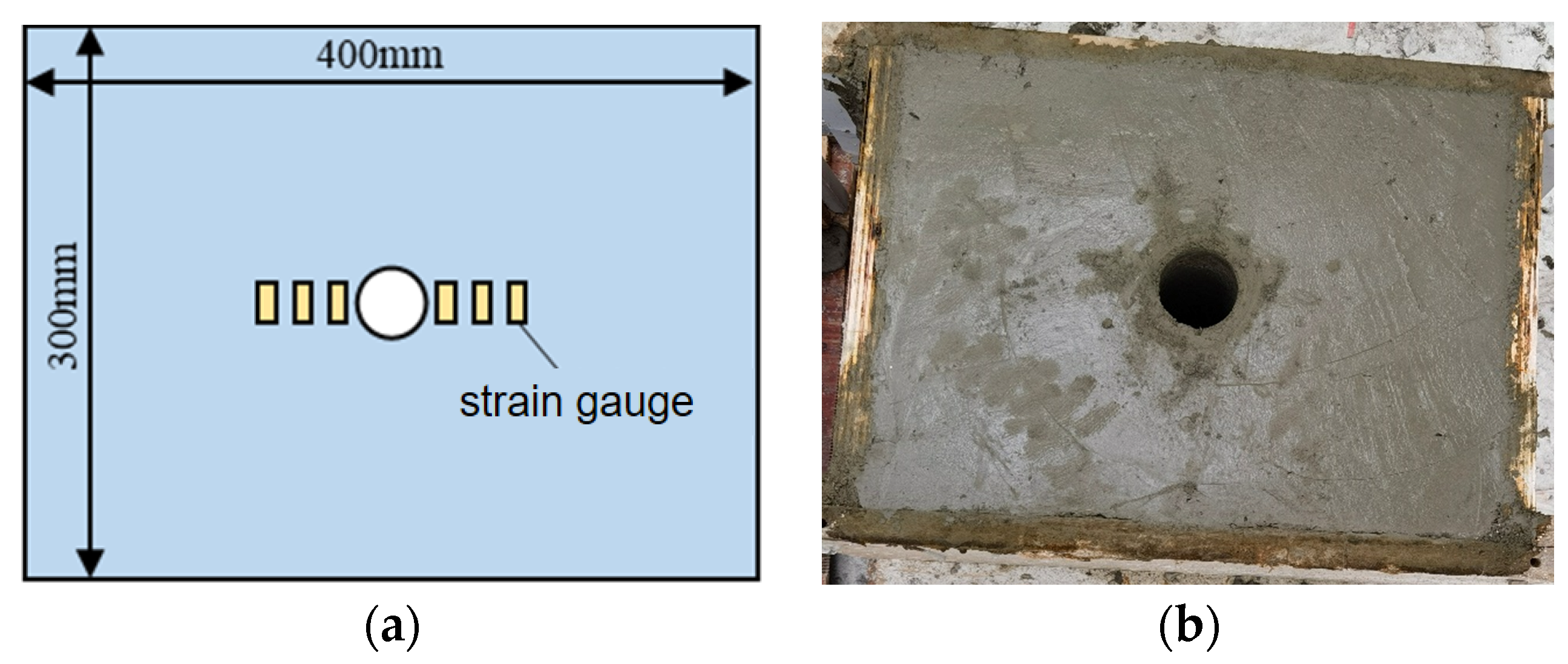
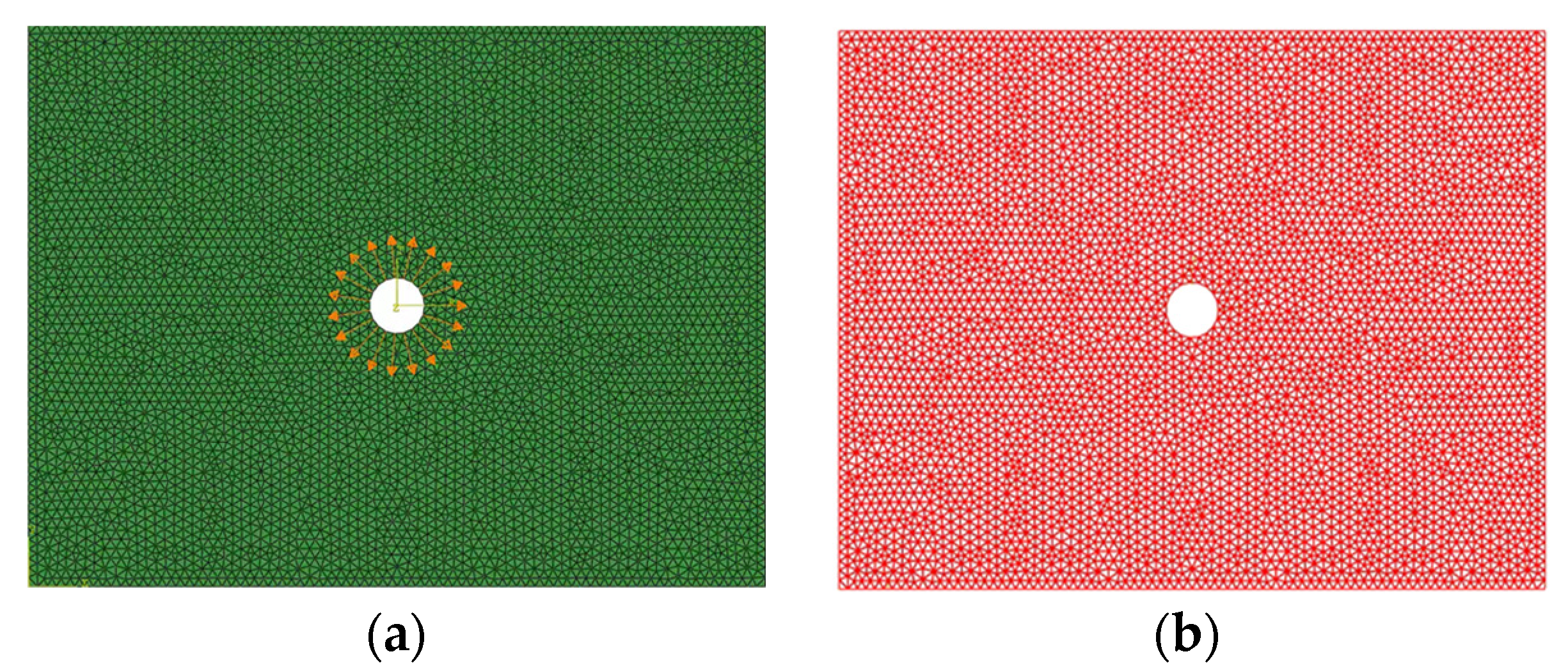
3.1. Simulation Verification

In this section, a simulation verification is conducted with the expansion fracturing experiment. Concrete specimens are made for static fracturing tests, and the Abaqus software is used to simulate the expansion fracturing process.
The test schematic of static fracturing is shown in Figure 4a, the dimensions of the specimen are 400 mm length, 300 mm width, and 300 mm thickness. The hole diameter of the test specimen is 42 mm, and six strain gauges are arranged at 10 mm, 30 mm, and 50 mm from the borehole for strain monitoring. As shown in Figure 4b, concrete specimens are made for static fracturing tests, specimens are demolded after 24 h, the standard curing room is maintained for 28 days, and the mixture proportion used for the specimens is listed in Table 2.
The numerical model of static fracturing is shown in Figure 5; the cohesion element is inserted in the numerical model, which is dependent on mesh partitioning. Triangular meshes are chosen as the basis for cohesion elements, with a mesh size set to 0.005. Considering the slow expansion and cracking process of the static fracturing agent, this problem can be simulated as a quasi-static issue. Explicit dynamic analysis is selected for the numerical simulation and a displacement of 0.01 mm is uniformly applied to the cohesion element nodes around the pre-drilled circular area. In the simulation, the mechanical parameters of the concrete specimens are shown in Table 3.
Test and simulation results of expansion fracturing are shown in Figure 6. From Figure 6a,b, the failure forms of concrete in the laboratory test and numerical simulation are basically consistent. From Figure 6c, the strain growth in the simulation is relatively smooth. Due to the presence of microcracks in the concrete specimens during the manufacturing process and the varying degrees of cementation between the internal aggregates and mortar, the cracks will rapidly propagate when the expansion pressure increases to a certain value, causing a sharp increase in the surface strain of the specimen. Additionally, there is pressure loss during the radial release of the static cracking agent in the experiment, which is not accounted for in the numerical simulation. Generally, the trends and values of the strain curves in the test and simulation are also close. This confirms the accuracy and applicability of the simulation method used in this paper.

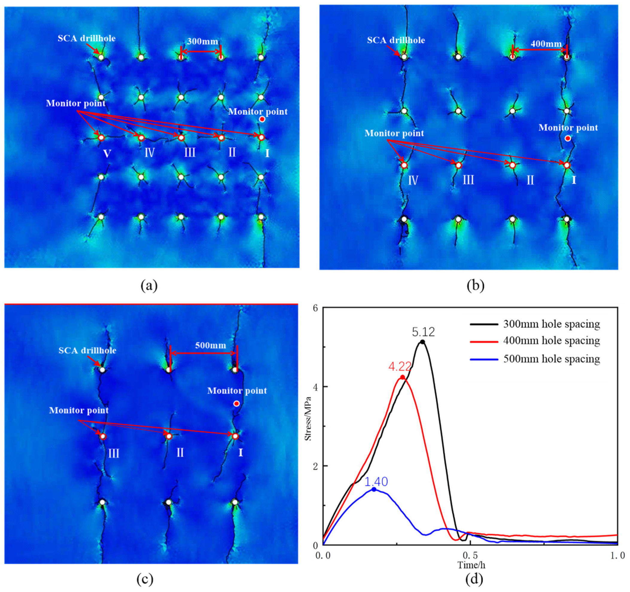
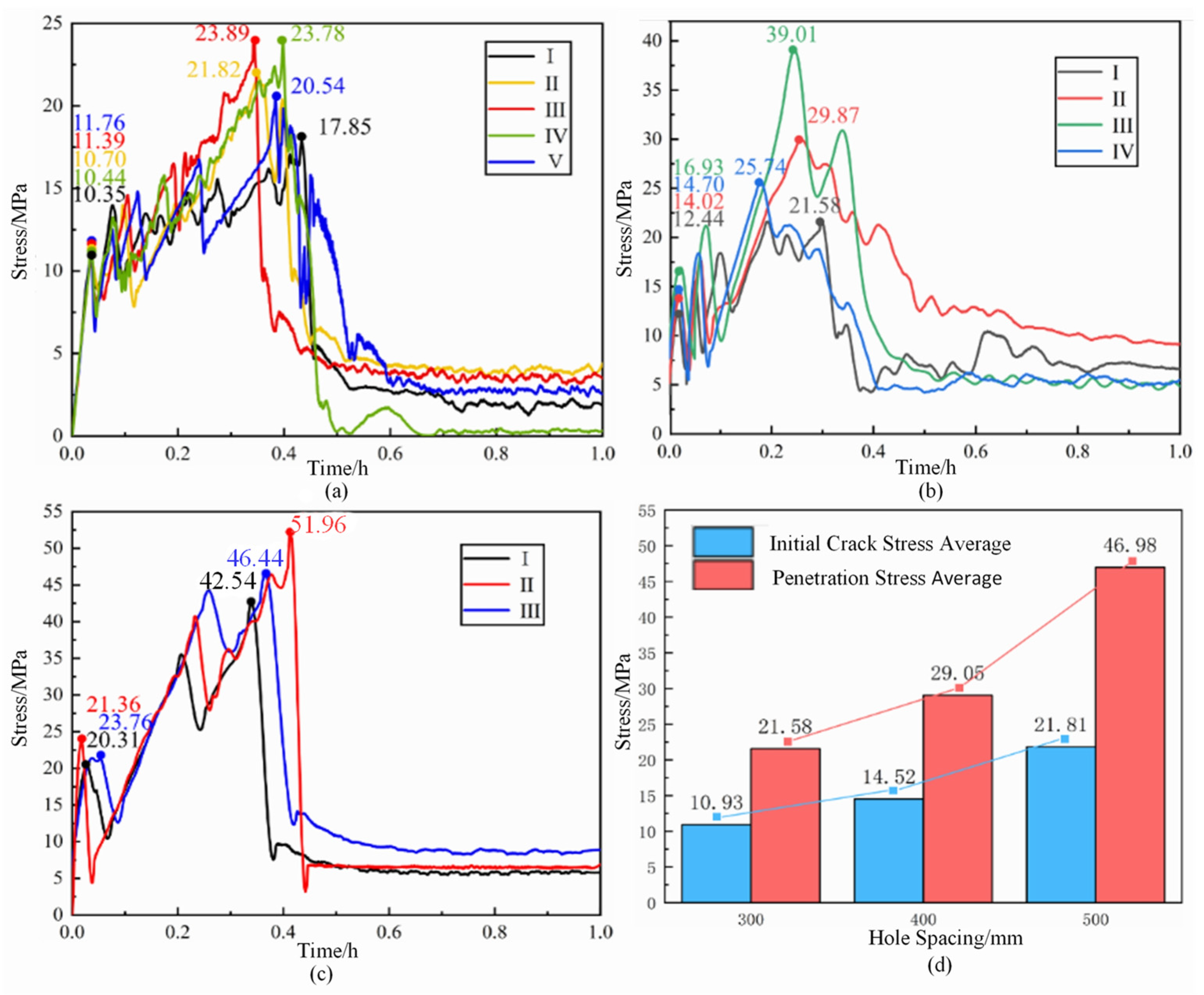
3.2. Optimization Design of Drilling Parameters

In this section, the fracturing effect of the static crushing agent with different hole spacings is simulated using Abaqus numerical software. Based on the background of the expansion project at a mine, the size of the numerical model is set to 2000 mm in height and length to match the site conditions. The boreholes are arranged with spacings of 300 mm, 400 mm, and 500 mm, totaling 25, 16, and 9 boreholes, respectively. The left boundary of the model is constrained, the right boundary is a free surface, and the distance from the right-side boreholes to the free surface is equal to their spacing. The confining pressure of the top boundary is set to 5 MPa, based on the overlying strata stress of the mining face. The mechanical parameters of simulation are selected based on the performance testing results of the rock sample from on-site engineering, as shown in Table 1. To facilitate the comparison and analysis of the evolution characteristics of the expansion force of the SCA, the total iteration steps of the expansion simulation under different working conditions are equivalently replaced by one hour.
The fracturing effects under different hole spacings are shown in Figure 7. From Figure 7a, for the model with a 300 mm hole spacing, three to four large cracks and numerous microcracks are produced around the holes, resulting in a higher number of cracks. From Figure 7b, for the model with a 400 mm hole spacing, two to three large cracks and fewer microcracks are generated. While for the model with a 500 mm spacing, mostly two to three large cracks are formed, as shown in Figure 7c. Furtherly, the stress at the midpoint between two holes closest to the free surface was monitored, and the results are shown in Figure 7d. The maximum stresses at the midpoint stress monitoring points for the 300 mm, 400 mm, and 500 mm models are 5.12 MPa, 4.22 MPa, and 1.40 MPa, respectively. The greater the stress at the monitoring point between two expansion holes, the more significant the influence of the static cracking agent’s expansion stress, indicating a better fracturing effect.
Monitoring the stress around the model middle holes, stress changes at monitor points I, II, III, IV, and V are depicted in Figure 8. from analysis of Figure 8a–c, sharp drops in stress–time curves indicate the formation of cracks. By comparing the fluctuating number of stress curves, the stresses required for initial fracturing and complete breakage of the rock mass increase with larger hole spacing. Smaller hole spacing results in more cracks around the holes, leading to better fracturing effects. Concretely, from statistical analysis of the stress curves, as indicated in Figure 8d, the initial fracturing stresses of the rock mass under different hole spacings are 10.93 MPa, 14.52 MPa, and 21.81 MPa, while the complete breakage stresses of the rock mass are 21.58 MPa, 29.05 MPa, and 46.98 MPa, respectively.

4. Engineering Application of Roadway Expansion Using SCA

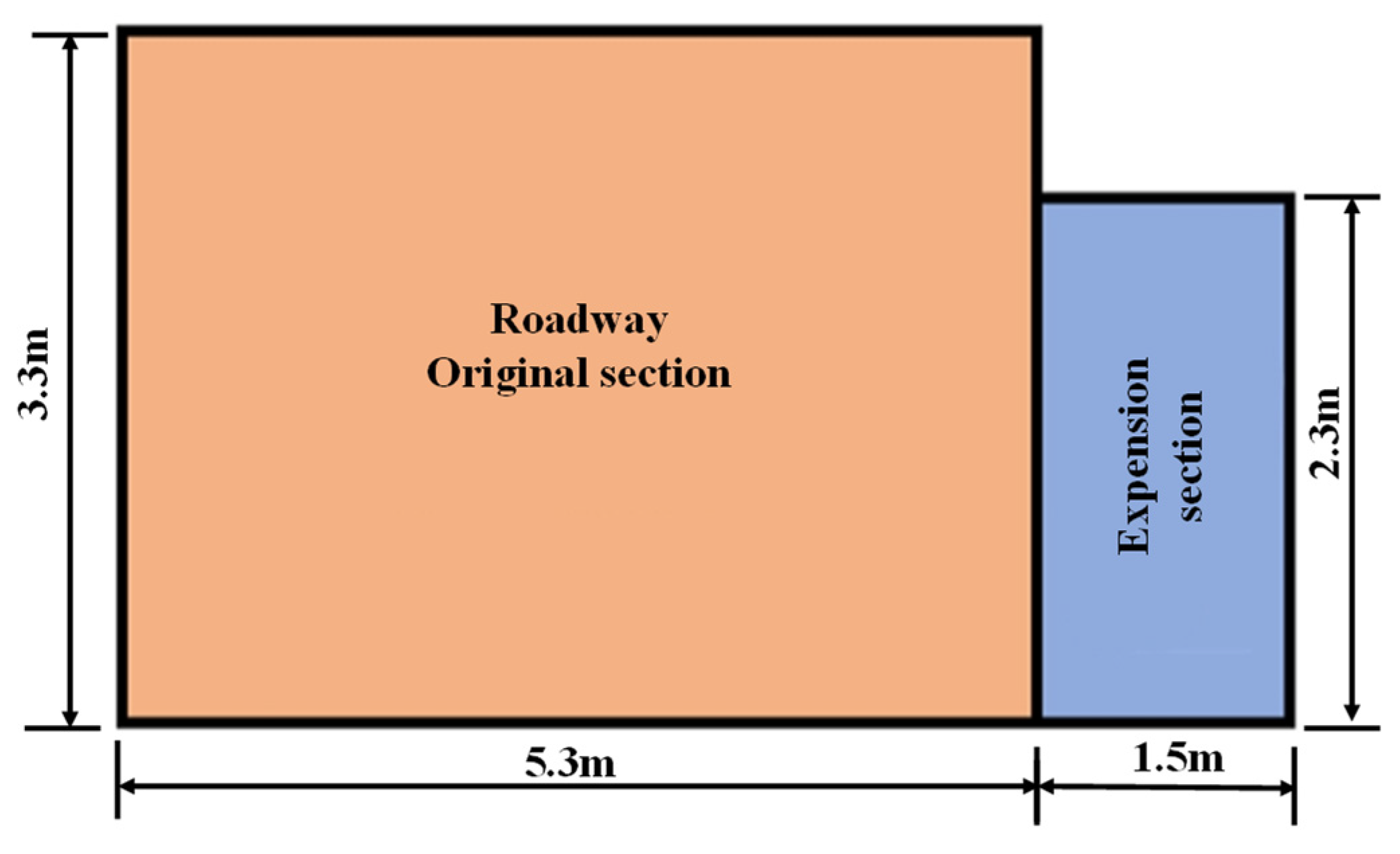
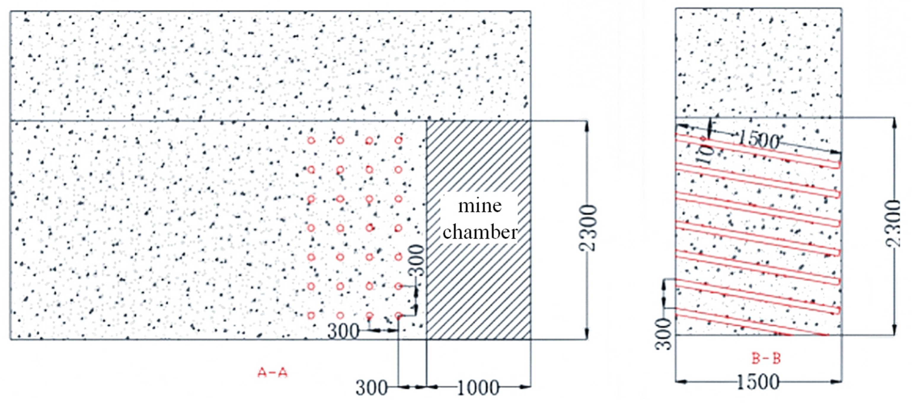
4.1. Scheme Design of Roadway Expansion

For this mine, due to the need to add an additional transportation track to the 2# coal-centralized transportation lane, the current lane width does not meet the requirements for installation, hence an expansion is needed. The specific design of the lane expansion is shown in Figure 9. The lane has a rectangular cross-section with a 5.3 m width and 3.3 m height. The expanded section has a height of 2.3 m, a depth of 1.5 m, and a length of 30 m.
When applying static cracking agents to rock fracturing projects, the hole diameter should not be less than 20 mm and should not exceed 50 mm, and drilling with diameters of 35 mm and 42 mm is widely used. Multiple expansion stress tests and field practice have verified that 42 mm hole diameter drilling is less likely to experience blowouts; when using static cracking agents to fracture rock, the construction area must have a free face. Larger hole diameters result in more severe blowout phenomena, using 42 mm diameter downward drilling can prevent hole flushing and slurry leakage [26]. In this project, the expansion drilling layout is determined by the on-site rock mechanical properties and geometric dimensions. A borehole diameter of 42 mm is selected. To provide a free surface for SCA roadway expansion, a chamber measuring 2300 mm in height, 1500 mm in depth, and 1000 mm in length needs to be generated at the end of the lane. Subsequently, boreholes are drilled into the chamber end and charged with SCA. A borehole diameter of 42 mm and a drilling depth of 1500 mm are selected. To facilitate grouting and prevent leakage, drilling is conducted at a 10° downward angle. In a workday, a total of 28 boreholes are constructed. The drilling layout design is shown in Figure 10.
Based on Section 2, the static cracking agent with 0.3 water–cement ratio is selected. Considering underground construction conditions, a 300 mm hole spacing is selected to ensure fracturing effectiveness. The amount of static cracking agent used per hole is calculated according to Equation (2):
Q = 1 + σ S L q
where Q is the quantity of static cracking agent per hole (g); σ is the loss rate of the static cracking agent; S is the area of the borehole bottom (cm2); L is the depth of the borehole (cm); and q is the required quantity of cracking agent per unit volume (cm3).
On-site, the drilling depth is 150 cm, and the area of the borehole bottom is approximately 13.85 cm2. Considering factors such as drilling fluid leakage, the loss coefficient of static cracking agent is taken as 0.2. Calculating according to Equation (2), the required amount of static cracking agent for a single borehole is approximately 5 kg.

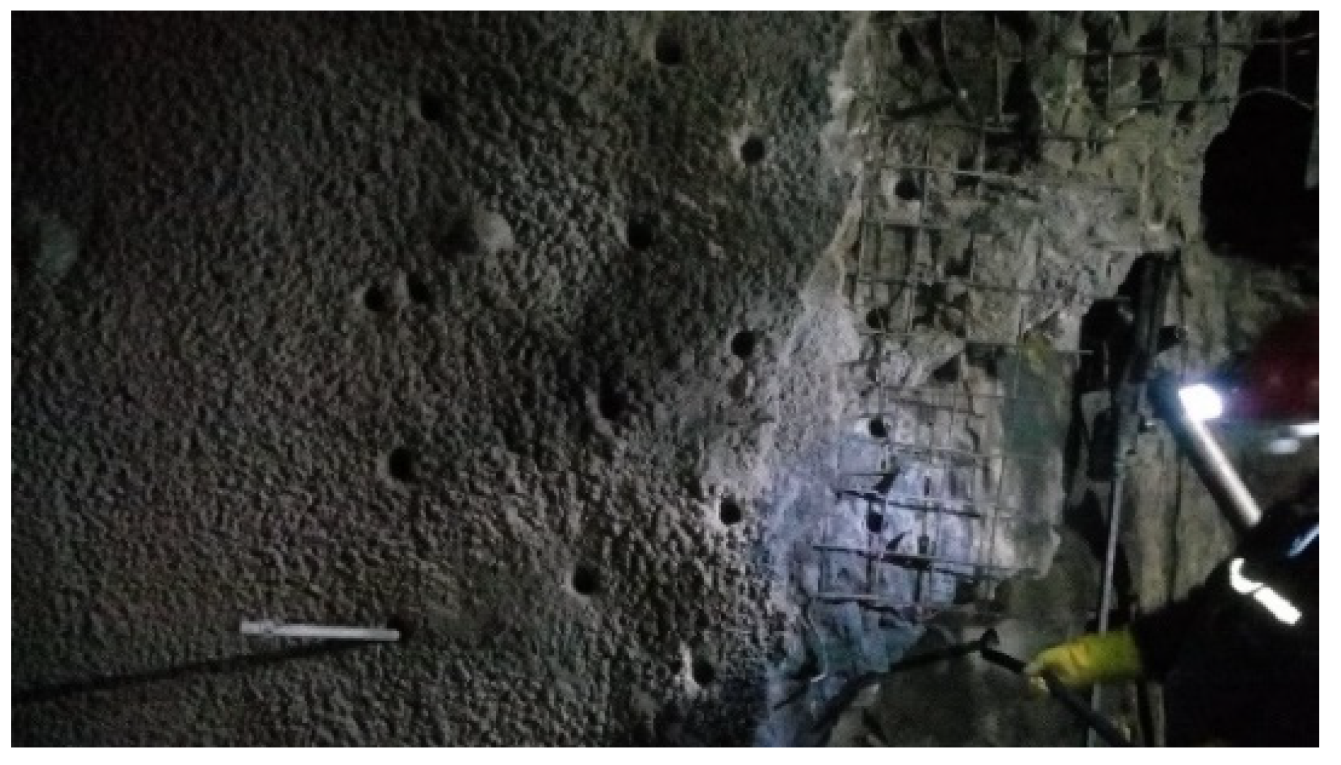
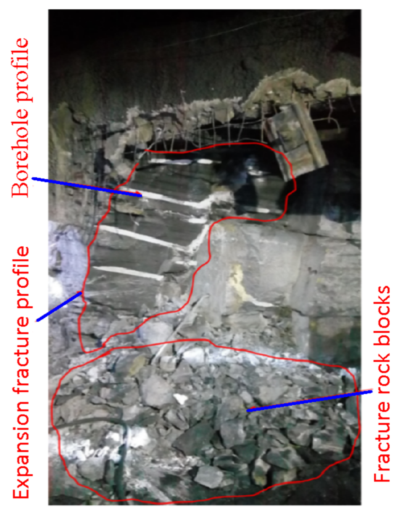
4.2. Construction Techniques and Effectiveness

The construction process for static cracking agent at the project site is as follows: Remove external shotcrete and steel mesh—42 mm borehole drilling. Mix static cracking agent dry material with water according to the water–cement ratio. Pour static cracking agent slurry. Wait for the static cracking agent to expand and crack the lane-side rock. Extract stone blocks along the fissures with pneumatic pick and drill. Support with shotcrete. Complete expansion. The on-site drilling construction results of the roadway expansion are shown in Figure 11.
After the static cracking agent is injected into the boreholes, the crack propagation effect of roadway rock mass is as depicted in Figure 12. During roadway expansion, faint rock fracturing sounds can be heard during the reaction period. After 8 h of grouting, cracks begin to emerge around the drill hole and progressively extend outward, with through-cracks forming first around the longitudinal boreholes. As these cracks interconnect, their width increases over time. Finally, the cracks primarily extend longitudinally across the face, accompanied by minor transverse cracks. Considering the coal mine’s construction schedule, the roadway expansion work needs to be carried out immediately 12 h after the static cracking agent infusion. The pneumatic pick and pneumatic drill are used to dig out rocks along the cracks, speeding up the roadway expansion process. After the expansion, observing the rock fracture surface, as shown in Figure 13, the cracks induced by the static cracking agent develop vertically along the boreholes into larger surfaces, demonstrating a clear fracturing effect for roadway expansion.
Because explosive use is restricted at the construction site of this mine, and large rock-breaking equipment could not be used due to space limitations, the use of only pneumatic drills and pickaxes to break the rock and expand the roadway had a low efficiency, with a daily progress of only 0.5 m/day. However, after using static cracking agents, the daily progress increased to at least 1.2 m/day, significantly improving the efficiency of the roadway expansion, reducing the time required for the expansion, saving labor, and generating substantial economic benefits.

5. Conclusions

In this paper, for a roadway expansion project of the central transportation lane of the mine, the mechanical parameters of the roadway surrounding rock was tested, the expansion properties of the static crushing agent (SCA) with different water–cement ratios were obtained, and then, the cracking process of the surrounding rock by SCA was also characterized using laboratory tests and numerical simulation. Finally, using SCA technology to expand the roadway was proposed, and the construction effect on the roadway expansion project was discussed. The following conclusions can be obtained:
(1) For a roadway expansion project, the mechanical parameters of the surrounding rock can be obtained by laboratory testing, with a tensile strength reaching 5.82 MPa. Performance tests of the static cracking agent determined the optimal water–cement ratio of SCA and revealed the variation pattern of expansion stress over time, indicating that the maximum expansion stress of SCA can reach 75.9 MPa. SCA can effectively fracture the roadway surrounding rock.
(2) For rock mass with 300 mm, 400 mm, and 500 mm hole spacings, the midpoint stress between drill holes in the rock mass can reach 5.12 MPa, 4.22 MPa, and 1.40 MPa; the initial fracturing stress around drill holes in the rock mass are 10.93 MPa, 14.52 MPa, and 21.81 MPa; and the complete breakage stresses of the rock mass are 21.58 MPa, 29.05 MPa, and 46.98 MPa, respectively. Generally, smaller hole spacing results in more cracks around the holes, leading to better fracturing effects.
(3) For the engineering requirement of a 2.3 m high and 1.5 m deep roadway expansion, the technology parameters using SCA were obtained, as follows. Because a smaller hole spacing can lead to a better fracturing effect on the rock mass, a hole spacing of 300 mm is selected. Additionally, a 42 mm borehole diameter and a drilling depth of 1500 mm were determined based on the on-site construction conditions. Industrial test results showed that this static cracking technology can effectively fracture the roadway surrounding rock, facilitating the engineering construction of the roadway expansion.

Author Contributions

Conceptualization, R.Y., Z.L. and Q.Z.; formal analysis, R.Y., Z.L. and Q.Z.; investigation, M.L., H.L. and Y.L.; writing—original draft, Q.Z., W.W., M.L., Z.L. and R.Y.; data curation, M.L., H.L. and Y.L.; writing—review and editing, R.Y., Z.L., Q.Z. and W.W.; funding acquisition, R.Y. and Q.Z. All authors have read and agreed to the published version of the manuscript.

Funding

This research was funded by the National Natural Science Foundation of China, grant number 52174109; the Program for Innovative Research Team (in Science and Technology) in University of Henan Province, grant number 22IRTSTHN005; the Key Research and Development Project of Henan Province, grant number 232102321130; the Key Research Project of Institutions of Higher Education in Henan Province, grant number 24A580001; and the National Natural Science Foundation of Henan Province, grant number 232300420303.

Institutional Review Board Statement

Not applicable.

Informed Consent Statement

Not applicable.

Data Availability Statement

Data are contained within the article.

Conflicts of Interest

The authors declare no conflicts of interest.

References

  1. Yan, C. Study on Cumulative Damage Effects and Stability of Rock Mass under Blasting Loading. Ph.D. Thesis, Central South University, Changsha, China, 2006. [Google Scholar]
  2. Luo, Y.; Cui, X.R.; Shen, Z.W. Application Study on Controlled Blasting Technology with Shaped Charge in Rock Mass. Chin. Q. Mech. 2007, 28, 234–239. [Google Scholar]
  3. Zong, Q.; Liu, Q.-H. Application Research on Cutting Technology of Mid-deep Hole Blasting in Coal Mine Rock Tunnel. Blasting 2010, 27, 35–39. [Google Scholar]
  4. Li, G.; Niu, L.; Li, W. Study on rapid excavation technology for hard rock roadway in coal mine. Int. J. Coal Sci. Technol. 2018, 46, 13–20. [Google Scholar]
  5. Yang, R.; Li, C.; Chen, J.; Zou, F.; Wang, Y.; Xiao, C.; Zhang, Z. Development history and new technology research progress of rock roadway blasting excavation in coal mines in China. Coal Sci. Technol. 2023, 51, 224–241. [Google Scholar]
  6. Duan, K. Maintenance of roadways in soft rocks by destress blasting of roadway-rib. J. China Coal Soc. 1995, 20, 311–316. [Google Scholar]
  7. Zheng, W.; Li, R.; Xu, L.; Hou, X. Review and analysis on research and application of static crushing technology. J. Harbin Inst. Technol. 2021, 53, 190–200. [Google Scholar]
  8. Xie, Y.; Yang, G.; Huang, X. Experimental Research on Mechanical Properties of Static Breaking Agents. Saf. Coal Mines 2019, 50, 9–16. [Google Scholar]
  9. Li, Y. Experimental Study on Influence of Water Temperature and Water Agent Ratio on Expansion Performance of Soundless Cracking Agent. Mine Constr. Technol. 2019, 40, 32–35+22. [Google Scholar]
  10. Li, Y.; Ma, Q. Test and Analysis on Reaction Temperature Variation of Static Cracking Agent. Chin. J. Undergr. Space Eng. 2013, 9, 1282–1289. [Google Scholar]
  11. Sheng, H.; Lu, X.; Zhou, Z.; Huang, J. Test and Analysis on Change of Volume Expansion Ratio of Static Cracking Agent. Coal Technol. 2017, 36, 80–82. [Google Scholar]
  12. Ma, D.D.; Ma, Q.Y.; Yuan, P. Test and Analysis on Air Temperature and Water Temperature for Expansion Performance of Static Cracking Agent. Blasting 2014, 12, 124–128. [Google Scholar]
  13. Xu, L.; Ni, H. Performance Testing and Research of Static Demolition Agents. Sichuan Build. Mater. 2013, 39, 82–84. [Google Scholar]
  14. Li, P.; Nie, G.-H. Study on the Static Cracking Agent. J. Hubei Univ. Natl. Nat. Sci. Ed. 2012, 30, 159–162. [Google Scholar]
  15. De Silva, V.R.S.; Ranjith, P.G.; Perera, M.S.A.; Wu, B.; Wanniarachchi, W.A.M. A low energy rock fragmentation technique for in-situ leaching. J. Clean. Prod. 2018, 204, 586–606. [Google Scholar] [CrossRef]
  16. Xu, D. Development and Application of Static Demolition Technology. Mod. Min. 2012, 27, 105–106+109. [Google Scholar]
  17. Jiang, N.; Xu, Q.; Long, Y.; Liao, Y.; Lin, W. Expansive pressure characteristic and borehole parameter analysis on large scale borehole soundless cracking. Explos. Shock Waves 2015, 35, 467–472. [Google Scholar] [CrossRef]
  18. Feng, Y. Experimental Research and Apply on the Soundless Cracking Agent. Master’s Thesis, AnHui University of Science and Technology, Huainan, China, 2010. [Google Scholar]
  19. He, S. Experimental Study on Static Blasting Fracturing Technology of Hard Rock. Master’s Thesis, China University of Mining and Technology, Xuzhou, China, 2022. [Google Scholar]
  20. Gao, T.-W.; Wang, H.-L. Application of Non-explosive Demolition Method of Tennel Extension Project in Coal Mine. Blasting 2011, 28, 98–99. [Google Scholar]
  21. Li, K.; Liang, Y. Application and Analysis of Static Demolition Technology in Expanding Roadway Cross Sections in Coal Mines. Saf. Coal Mines 2010, 41, 126–128. [Google Scholar]
  22. DZ/T 0276-2015; Regulation for Testing the Physical and Mechanical Properties of Rock. Ministry of Land and Resources of the People’s Republic of China: Beijing, China, 2015.
  23. GB/T JC506-2008; Soundless Cracking Agent. National Development and Reform Commission of the People’s Republic of China: Beijing, China, 2008.
  24. Sun, L.; Li, C.; Tie, Y.; Hou, Y.; Duan, Y. Experimental and numerical investigations of adhesively bonded CFRP single-lap joints subjected to tensile loads. Int. J. Adhes. Adhes. 2019, 95, 102402. [Google Scholar] [CrossRef]
  25. Jiang, Z.; Zheng, W.; Wang, Y.; Sun, P.; Lu, D.; Sun, L. The use of soundless chemical demolition agents in reinforced concrete deep beam demolition: Experimental and numerical study. J. Build. Eng. 2023, 69, 106260. [Google Scholar] [CrossRef]
  26. Wu, S.-L.; Zhai, C.; Xiang, X.-W.; Yu, X.; Tang, Z.Q. Experimental Study on Jet Orifice of Static Cracking Agent in Drilling Hole. Coal Technol. 2015, 34, 142–145. [Google Scholar]
Figure 1. Mechanics test of rock samples.
Applsci 14 09032 g001
Figure 2. Schematic diagram of the expansion force test equipment.
Applsci 14 09032 g002
Figure 3. Expansion stress–time curve of static cracking agent.
Applsci 14 09032 g003
Figure 4. The test schematic of static fracturing of a concrete sample. (a) Schematic diagram of the test; and (b) physical picture of specimen.
Applsci 14 09032 g004
Figure 5. The numerical model of static fracturing of the concrete sample. (a) Numerical model of static fracturing; and (b) cohesion element distribution of numerical model.
Applsci 14 09032 g005
Figure 6. Comparison of expansion fracturing test and simulation results. (a) Test specimens; (b) numerical model; and (c) monitoring data.
Applsci 14 09032 g006
Figure 7. Expansion fracturing results of rock mass. (a) 300 m hole spacing; (b) 400 m hole spacing; (c) 500 m hole spacing; and (d) middle stress between holes.
Applsci 14 09032 g007
Figure 8. Monitoring results of hole perimeter stress. (a) 300 m hole spacing; (b) 400 m hole spacing; (c) 500 m hole spacing; and (d) comparison of different hole spacings.
Applsci 14 09032 g008
Figure 9. Roadway support and expansion details.
Applsci 14 09032 g009
Figure 10. Layout design of SCA drilling.
Applsci 14 09032 g010
Figure 11. Construction results of SCA drilling.
Applsci 14 09032 g011
Figure 12. Roadway crack propagation after SCA charged.
Applsci 14 09032 g012
Figure 13. Roadway expansion effect.
Applsci 14 09032 g013
Table 1. The obtained rock mechanical parameters are listed in Table 1.
Rock TypeDensity
(kg/m3)
Compressive Strength (MPa)Tensile Strength
(MPa)
Elastic
Modulus
(GPa)
Poisson’s RatioInternal Friction Angle (°)Cohesion
(MPa)
Sandstone272067.45.8216.8740.2536.214.374
Table 2. Mix proportions of concrete (kg/m3).
Concrete GradeCementFine Agg.Coarse Agg.Water
C403986491155199
Table 3. Physical and mechanical property parameters of concrete specimen.
Specimen TypeDensity
(kg/m3)
Compressive Strength (MPa)Tensile Strength
(MPa)
Elastic Modulus (GPa)Poisson’s Ratio
C40 concrete240040.742.7932.50.2
Disclaimer/Publisher’s Note: The statements, opinions and data contained in all publications are solely those of the individual author(s) and contributor(s) and not of MDPI and/or the editor(s). MDPI and/or the editor(s) disclaim responsibility for any injury to people or property resulting from any ideas, methods, instructions or products referred to in the content.

