Article

Horizontal Distribution of Liquid in an Over-Row Sprayer with a Secondary Air Blower

1
Faculty of Technical Sciences, University of Warmia and Mazury in Olsztyn, Oczapowskiego 11, 10-719 Olsztyn, Poland
2
Department of Horticultural Machinery, Faculty of Horticulture, Mendel University in Brno, Valtická 337, 691 44 Lednice, Czech Republic
*
Author to whom correspondence should be addressed.
Appl. Sci. 2024, 14(19), 9036; https://doi.org/10.3390/app14199036 (registering DOI)
Submission received: 4 September 2024 / Revised: 1 October 2024 / Accepted: 5 October 2024 / Published: 7 October 2024

Abstract

:
The aim of this study was to determine the influence of boom height above a crop stand and the spacing between nozzles and diffusers in an over-row sprayer on the uniformity of the horizontal spray distribution and the uniformity of the air velocity distribution. The experimental setup involved a prototype over-row sprayer equipped with a boom with a working width of 8 m and ten air diffusers with spray nozzles. Air diffusers were connected to one or two nozzles each, and they were installed on the boom at intervals of 60, 80, and 90 cm. Terminal airflow velocity at a canopy is determined by the height of a sprayer boom and the diffuser spacing, ranging from around 2 m s–1 to around 27 m s–1. The sprayer boom should be positioned at a height of 50 cm above a crop stand due to the difference between the minimum and maximum airflow velocities. The horizontal spray distribution was more uniform when the sprayer was equipped with hollow-cone nozzles instead of flat-fan nozzles; hollow-cone nozzles should be applied if the distance between nozzles needs to be adjusted to the row width and row spacing. The analyzed coefficients did not exceed 10% when the boom was positioned 50 cm above the crop stand and when the nozzles were spaced 80 cm apart, which suggests that, in this configuration, sprayers equipped with hollow-cone nozzles can also be applied to close-grown crops.

1. Introduction

Intensive farming techniques require the use of plant protection chemicals to prevent the spread of pests, diseases, and weeds that reduce crop yields. These chemicals can also be toxic to humans and animals; therefore, they should be applied only when necessary [1,2,3,4,5], particularly because their residues can persist in various parts of protected plants for long periods of time. Crop-spraying operations should involve equipment that is in good technical condition, and chemicals should be applied in minimal effective doses [6,7,8]. To achieve this goal, the applied liquid should be uniformly distributed over the target crops [9,10,11]. A uniform spray distribution is also one of the requirements of sustainable agriculture, which aims to minimize the environmental impact of farming operations through the rational use of natural resources and agricultural inputs without compromising farming profits [12,13,14]. The position of spray nozzles above the crop stand should be optimized to achieve the above goal and to minimize spray drift [15,16]. In most commercial field sprayers, the boom is raised to a certain height above the crop stand and the nozzles are positioned on the boom at equal intervals. The nozzles should be spaced 50 cm apart and the boom should be positioned around 50 cm above the ground to ensure that the spray cones overlap and that the liquid is applied uniformly onto the target crops [16].
In row crops, chemicals should not be applied across the entire spray band, especially in the early stages of plant development, to minimize their environmental impact. Over-row sprayers are better suited for these types of production systems because the nozzles can be positioned at various locations on the boom, and their configuration can be adjusted to the cropping pattern. In over-row sprayers, the delivered dose can be precisely controlled and reduced by even 20% to 70% [2,17,18,19,20,21]. The effectiveness of spray treatments can be improved through the use of a secondary air blower (SAB) to ensure that the liquid is broadcast evenly onto all plants and on all sides of the stand [14,22,23,24,25]. However, the effect of the auxiliary air stream on the horizontal distribution of liquid in an over-row sprayer has never been investigated to date. Therefore, the aim of this study was to determine the influence of boom height above the crop stand and the spacing between nozzles and diffusers in an over-row sprayer on the uniformity of the horizontal spray distribution and the uniformity of the air velocity distribution.

2. Materials and Methods

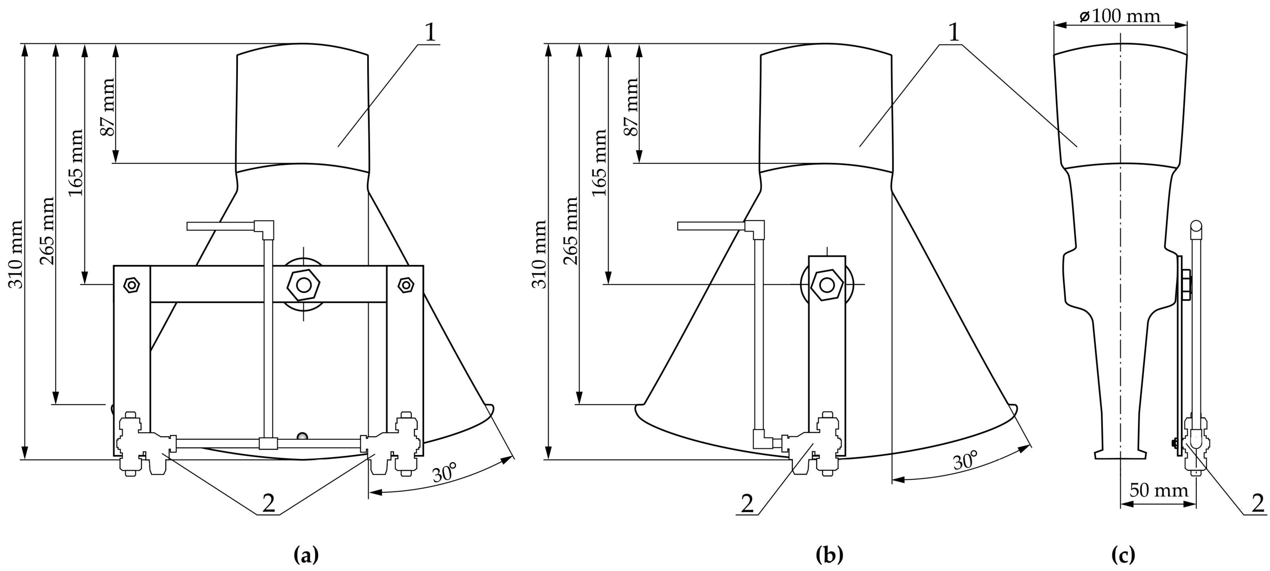
2.1. Experimental Setup

The experimental setup involved a mobile test stand (a trailed over-row sprayer equipped with an SAB; Figure 1). The prototype of the tested sprayer was developed by AGROLA Zdzisław Niegowski (Płatkownica, Poland) as part of a research project entitled “A family of field sprayers with an air sleeve”. The over-row sprayer was equipped with a 1 m3 sprayer tank and a hydraulic folding boom with a working width of 8 m. Ten diffusers manufactured by Marseplast Sp. z o.o. (Niepołomice, Poland) were installed on the boom (Figure 2). The diffusers were symmetrically positioned relative to the sprayer’s axis of symmetry on both sides. The basic geometric dimensions of the tested diffusers are presented in Figure 3. The diffuser’s sides were set at an angle of 30°, and the supplied air expanded as it exited the device. The diffusers were supplied with air by a radial fan connected to ten air ducts via a central plenum. Each air duct was connected to one diffuser. The fan was powered by the tractor’s power transmission system via a two-speed transmission with gear ratios of 0.22 (I) and 0.28 (II).
In the prototype over-row sprayer, each diffuser could be configured to work with one or two spray nozzles (Figure 3). To connect the diffuser to one nozzle, the nozzle was aligned with the diffuser’s axis of symmetry. To connect the diffuser to two nozzles, the nozzles were positioned at a distance of 9 cm from the diffuser’s axis of symmetry. The nozzle axis was shifted 50 mm forward relative to the diffuser axis and the spray cones were parallel to each other.

2.2. Experimental Design

The experiment was conducted in June 2021 at the Training Center for Plant Protection Techniques of the Faculty of Technical Sciences at the University of Warmia and Mazury in Olsztyn. The experiment was conducted under laboratory conditions to maintain a stable air temperature of 25 ± 1 °C and eliminate the effect of wind [26]. Each experimental variant was tested in triplicate, and the results were calculated based on the mean values of the analyzed parameters.
The experiment consisted of two stages. The uniformity of the air velocity distribution in an over-row sprayer equipped with an SAB was analyzed in the first stage of the study. Airflow velocity was measured using a Smart Sonda Testo 410i vane anemometer (Testo Sp. z o.o., Pruszków, Poland) with a measurement range of up to 30 m s–1, a velocity resolution of 0.1 m s–1, and ±3% accuracy. The anemometer was placed in a holder to stabilize the sensor and it was mounted parallel to the boom at a distance of 10 cm to 50 cm (at intervals of 10 cm), measured vertically from the air outlet in each diffuser. Each series of measurements began from the axis of the outermost diffuser and the anemometer was moved 5 cm along the spray boom each time. This procedure was used to measure airflow velocity along the axis of each diffuser and at equal distances from these axes of 5, 10, 15, 20, 25, 30, 35, 40, and 45 cm (for the largest distance between diffusers).
In the second stage of the experiment, the horizontal distribution of the spray liquid was analyzed in configurations that differed by the type of spray nozzle, the number of nozzles, and the nozzle position relative to the diffusers’ axes of symmetry. These measurements were conducted using a portable patternator (BBtechnika, Dzierzążenko, Poland). The patternator had a length of 3.1 m and a width of 1.5 m, and the gutter width was 10 cm. The liquid flowing in each gutter was collected into 500 mL measuring cylinders (Figure 4) with 10 mL graduations. The experimental factors were as follows.
  • Constants:
  • Distance (height) between the boom of the over-row sprayer with an SAB and the patternator—50 cm;
  • Working pressure—0.3 MPa.
2.
Independent variables:
  • Type of nozzle—a Lechler 110-03 flat-fan nozzle and a Lechler TR 80-03C hollow-cone nozzle for viticulture and orchard crops;
  • Nozzle position—one nozzle positioned along the diffuser’s axis of symmetry and two nozzles positioned on both sides of the diffuser’s axis of symmetry at a distance of 9 cm from that axis;
  • Configuration of the spray boom—without an SAB, with an SAB and the fan operating in first gear, and with an SAB and the fan operating in second gear.
The following procedure was applied to measure the horizontal spray distribution:
  • The working parameters of the sprayer were set, including the working pressure of the spray liquid, the airflow rate controlled by the fan’s rotational speed (two speed settings), the height (distance) of the sprayer boom above the patternator, and the type and number of nozzles (nozzle position relative to the diffuser’s axis of symmetry);
  • The tractor’s power transmission system was activated to transmit mechanical power to the sprayer pump and, if required, to the fan;
  • The tractor’s engine was set to a nominal rotational speed (1600 rpm);
  • The working pressure of the spray liquid was set at 0.3 MPa (pure water was used in the experiment);
  • Measuring cylinders were positioned under the patternator gutters and the liquid transferred into each gutter was collected into the cylinders for 60 s;
  • The volume of liquid collected in each cylinder was read and recorded in an Excel spreadsheet.
According to Polish regulations [27], when spray-distribution uniformity is measured with an optical patternator system, the volume of the liquid collected from each gutter into individual cylinders should not differ by 15%, and these parameters should not be exceeded in more than 10% of the measurements. The coefficient of non-uniformity (u) of the horizontal spray distribution was calculated using the following formula:
u = 100 × n g + n d n r
where ng is the number of measuring cylinders where the volume of collected liquid exceeded the upper limit of the measurement range, nd is the number of measuring cylinders where the volume of collected liquid was below the lower limit of the measurement range, and nr is the number of patternator gutters (measuring cylinders) collecting liquid during the measurement.
The spray quality was also assessed by calculating the coefficient of variation (CV), which is used in measurements involving patternators with digital liquid-level sensor technology [28], as follows:
C V = 100 × 1 n r 1 i = 1 n r V i V ¯ 2 V ¯
where Vi is the volume of liquid collected from the i-th patternator gutter (mL) and V ¯ is the average volume of liquid collected from one patternator gutter (mL).
The CV was calculated as the ratio of the standard deviation to the average liquid volume in each measuring cylinder and it was expressed as a percentage. To ensure the effective distribution of a spray liquid, the CV should not exceed 10% [28,29,30,31,32].

2.3. Statistical Analysis

The data collected during the measurements of the air velocity distribution and the spray-distribution uniformity in the horizontal plane were statistically processed using Statistica PL v. 13.3 (TIBCO, Paolo Alto, CA, USA) software at a significance level of α = 0.05. To determine the uniformity of the air velocity distribution using individual diffusers, measurements of air velocity were conducted only along the diffuser’s axis of symmetry and at a distance of 5 cm from that axis. To determine the uniformity of the air velocity distribution in the horizontal plane, all measurements were considered in the analysis but they were divided into three groups of data based on the distance between diffusers. The variations in the examined parameters were determined using the Student’s t-test for independent samples and an analysis of variance (ANOVA). Homogeneous groups were identified using Tukey’s test. The mean values and standard deviations of the coefficient of non-uniformity and the CV for the air velocity distribution and spray distribution in the horizontal plane were determined using descriptive statistics.

3. Results and Discussion

The results of the measurements of the uniformity of the air velocity distribution using diffusers in an over-row sprayer are presented in Table 1. As expected, the fan’s rotational speed and, consequently, the airflow velocity increased when the fan was operated in second (II) gear. The difference in the airflow velocity between the second and the first gears ranged from around 10% (diffuser No. 3) to around 25% (when the diffuser was positioned 50 cm above the patternator). The airflow velocity decreased with an increase in the diffuser height above the patternator, and the observed differences were statistically significant. At the minimum diffuser height (10 cm), the airflow velocity was 140% (first gear) or 125% (second gear) higher on average relative to that noted at the maximum diffuser height (50 cm). These differences could be attributed to the diffusers’ conical shape, which caused the supplied air to expand. As a result, the air became diluted over the distance from the diffuser.
Smaller differences in the airflow velocity were noted when the fan was operated in second gear, which could be explained by the fact that the airflow was attenuated by the fan’s mechanical components, central plenum, and air ducts due to the higher airflow rate and velocity [33,34]. During spray treatments in orchards, the boom is positioned at a distance of 1 m from tree canopies and the airflow velocity at the diffuser outlet should be around 10 m s–1. Upon reaching the canopy, the airflow velocity should be reduced by nearly 50% [4]. Field crops can form dense stands, especially in phenological stages characterized by rapid plant growth, which is why the airflow velocity should not be reduced below the value applied to orchards. According to Gupta [35], an airflow velocity of up to 15 m s–1 is sufficient to distribute the spray liquid evenly throughout the crop stand while reducing the loss of chemicals and minimizing soil pollution. Therefore, the analyzed diffusers were positioned at a minimum height of 20–30 cm above the stand. It should be noted that two fan-speed settings can facilitate spraying operations because the airflow velocity can be adjusted to the height of the sprayer boom and the plant’s growth stage. The airflow velocity at the diffuser outlet can also be modified to change the size of the droplets reaching the treated plants [36,37].
The registered airflow velocities significantly differed on both sides of the boom and partly when the diffusers were positioned along the sprayer’s longitudinal axis (when the fan was operated in second gear). These results pointed to a design error in the central plenum: the air generated by the radial fan was not evenly distributed across the diffusers. This error prevented the uniform distribution of the spray liquid along the horizontal plane; this should be eliminated in the next version of the prototype sprayer. The airflow velocity values were not significantly influenced by the interaction effect between the diffuser height and the diffuser’s position relative to the sprayer’s axis of symmetry, whereas the interaction effects of other the experimental factors significantly affected the airflow velocity.
The airflow velocities at both fan-speed settings at a diffuser height of 20 cm are compared in Figure 5. Their distribution was not symmetrical relative to the sprayer’s longitudinal axis or the axis of each individual diffuser. This observation could partly be attributed to the same design error in the central plenum as well as the fact that the diffusers were not precisely installed on the boom, so their axes of symmetry were not always perpendicular to the sprayed surface.
In the next stage of the study, the airflow velocity was measured when the diffusers were positioned at different heights and at different intervals. The results of these measurements are presented in Table 2. The greatest variations in the airflow velocity were noted at the lowest diffuser height (10 cm), regardless of the diffuser spacing. On average, the airflow velocity at the most distant measurement points was 187% (minimal diffuser spacing) or even 1160% (maximal diffuser spacing) lower than that noted along the diffuser axis. Obviously, the auxiliary air stream does not have to be evenly distributed along the entire boom width when herbicides are applied to protect plants grown in widely spaced rows and to control inter-row weeds. Inter-row weeds should be mechanically controlled, although mechanical weeding does not eliminate intra-row weeds or weeds growing close to the plants inside the crop safety zone [1,17]. Over-row sprayers where the position of the spray nozzles and air diffusers can be adjusted by the user are best-suited to these types of crop stands, and nozzles and diffusers should be positioned symmetrically above the spray band. Spray droplets have kinetic energy but they are swept along by a moving stream of air [3,38]. Therefore, the airflow velocity should be kept constant across the entire spray band, unless the target crop has a growth habit that does not require such an approach. In this case, the airflow velocity in sectors with different plant densities should be adjusted to ensure that the liquid reaches the lowest segment of the stem [23]. However, if this factor is disregarded, protective treatments can be applied to strips with a width of up to 50 cm when diffusers are positioned 10 cm above the ground, and this configuration is ideal for crops grown in strips with a width of up to 30 cm.
The airflow velocity was equalized (no significant differences in the mean airflow velocity) when the diffusers were positioned at a minimum height of 30 cm (at 80 cm intervals) or 40 cm (at 90 cm intervals). In this case, the difference between the minimum and maximum airflow velocities at different distances from the diffuser axis could reach 50%. This could be attributed to the imprecise installation of the diffusers or the uneven distribution of air streams across the diffusers, but mainly to the insufficient overlap of air streams from adjacent diffusers. The uniformity of the spray distribution could be improved by increasing the boom height above the crop stand. For this reason, optimal spray-distribution uniformity at both fan speeds and at all diffuser intervals could be achieved when the boom and diffusers were positioned 50 cm above the crop stand. To minimize airborne spray drift, the boom height should not be increased [14,26,39].
The effects of the interactions between the nozzle and diffuser settings were analyzed in the next step of the study by positioning the diffusers at a height of 50 cm above the patternator. The horizontal distribution of the liquid broadcast by the flat-fan nozzles is presented in Figure 6. The greatest peak-to-peak deviations from the mean values were observed in the proximity of the first two diffusers, positioned closest to the sprayer’s axis of symmetry. The spray rate was highest around the sprayer’s axis of symmetry where the diffusers and the corresponding nozzles were spaced 60 cm apart. The lowest was between the second and the third diffuser, i.e., in the segment of the boom where the nozzles and diffusers were spaced 90 cm apart. In these cases, the auxiliary air stream intensified the described effect by increasing the amount of spray liquid in the central part of the boom and decreasing the amount of spray liquid between the second and the third diffusers. Therefore, it could be assumed that the spray coverage was more uniform when the diffusers and nozzles were spaced 80 cm rather than 60 cm or 90 cm apart.
Similar observations were made when analyzing the uniformity of the horizontal spray distribution (Table 3). In each analyzed case (excluding the variant without an SAB where each diffuser was connected to one nozzle positioned along the diffuser’s axis of symmetry), more desirable values of the coefficient of non-uniformity and the CV of the horizontal spray distribution were noted in the boom segments where the nozzles were spaced 80 cm apart.
However, the recommended values [27,28] of these coefficients were achieved only in the variant without an SAB, where two hollow-cone nozzles were positioned on both sides of the diffuser’s axis of symmetry at a distance of 9 cm from the axis. The spray distribution in the horizontal plane was far less uniform when the SAB was activated (at both fan-speed settings), despite the fact that the airflow velocity was leveled at that height. Dai et al. [24] suggested that distribution uniformity could be improved by decreasing the relative angle between air and liquid streams, which would increase the moisture content of the auxiliary air stream and facilitate the transport of droplets to the canopy. When the over-row sprayer was equipped with flat-fan nozzles, a minor improvement in the values of the coefficient of non-uniformity and the CV of the horizontal spray distribution was noted only when the fan was operated in first gear and when the nozzles were spaced 80 cm apart, both in the variant with one and two nozzles. The values of the examined coefficients were least desirable when the analysis covered the entire boom and when the SAB was activated, the fan was operated in second gear, and each diffuser was connected to one nozzle positioned along the diffuser’s axis of symmetry(due to the CV of the horizontal spray distribution) or to two nozzles separated by a distance of 9 cm from the axis of symmetry (due to the coefficient of non-uniformity of the horizontal spray distribution). In the above scenario, the values of the examined coefficients were high (generally much above the recommended values), which confirmed previous observations that nozzles should be spaced 50 cm apart when a sprayer boom is positioned 50 cm above a stand [8,29]. The spacing between nozzles can be increased when crops are grown in widely spaced rows where the spray liquid has to be applied in the middle of each row or between rows.

4. Conclusions

In the analyzed configuration of nozzles and diffusers, air-assisted spraying improved liquid deposition in the proximity of the axes of hollow-cone nozzles, indicating that they could effectively be used in over-row sprayers when applied chemicals have to be directed onto plant rows and where air and liquid streams are required to penetrate all plant segments, including their lower parts.
The airflow velocity along the width of the sprayer boom at both fan-speed settings was determined by the boom height above the ground and the diffuser spacing. The uniformity of the air velocity distribution could be improved by positioning the diffusers at 60 cm intervals when the boom height was around 30 cm or at 80 cm and 90 cm intervals when the boom height was around 30–40 cm. However, due to the difference between the minimum and maximum airflow velocities, optimal results were achieved when the boom as positioned 50 cm above the crop stand.
In the three analyzed scenarios, the uniformity of the horizontal spray distribution was optimized when the nozzles and diffusers were spaced 80 cm apart. In this variant, the values of the coefficient of non-uniformity and the CV of the horizontal spray distribution generally decreased. The difference relative to the entire width of the boom with differently spaced nozzles reached 60%.
No significant differences in the analyzed coefficients were observed when the diffusers were connected to one or two nozzles. The CV of the horizontal spray distribution was lower in the variant where two nozzles were positioned at a distance of 9 cm from the diffuser’s axis of symmetry. In turn, the value of the coefficient of non-uniformity improved when each diffuser was connected to a single nozzle installed in the diffuser’s axis of symmetry. The difference between the above variants ranged from around 3% to around 22%.
If the interval between nozzles has to be increased above the recommended value of 50 cm, hollow-cone nozzles should be used instead of flat-fan cones, despite the fact that the former have a smaller spray-cone angle. When an SAB is not activated and when nozzles are spaced 80 cm apart, spray treatments can also effectively be applied to close-grown crops because the mean values of the coefficient of non-uniformity and the CV of the horizontal spray distribution did not exceed 10% in this scenario.

Author Contributions

Conceptualization, P.M. and A.L.; methodology, P.M. and A.L.; software, P.M.; validation, Z.K.; formal analysis, Z.K. and S.L.; investigation, A.L.; resources, A.L.; data curation, P.M. and A.L.; writing—original draft preparation, P.M. and Z.K.; writing—review and editing, P.M., Z.K., A.L., S.L., P.B. and V.M.; visualization, Z.K.; supervision, P.M., Z.K., A.L. and P.B.; project administration, A.L.; funding acquisition, A.L. All authors have read and agreed to the published version of the manuscript.

Funding

The presented research was funded by the Polish National Center for Research and Development (NCBR) within the framework of the project entitled “A family of field sprayers with an air sleeve” (No. MAZOWSZE/0002/19).

Institutional Review Board Statement

Not applicable.

Informed Consent Statement

Not applicable.

Data Availability Statement

The raw data supporting the conclusions of this article will be made available by the authors on request.

Conflicts of Interest

The authors declare no conflicts of interest.

References

  1. Carballido, J.; Rodríguez-Lizana, A.; Agüera, J.; Pérez-Ruiz, M. Field sprayer for inter and intra-row weed control: Performance and labor savings. Span. J. Agric. Res. 2013, 11, 642–651. [Google Scholar] [CrossRef]
  2. Terra, F.P.; Nascimento, G.H.; Duarte, G.A.; Drews, P.L.J., Jr. Autonomous agricultural sprayer using machine vision and nozzle control. J. Intell. Robot. Syst. 2021, 102, 38. [Google Scholar] [CrossRef]
  3. Hanif, A.S.; Han, X.; Yu, S.-H. Independent control spraying system for UAV-Based precise variable sprayer: A review. Drones 2022, 6, 383. [Google Scholar] [CrossRef]
  4. Li, J.; He, M.; Cui, H.; Lin, P.; Chen, Y.; Ling, G.; Huang, G.; Fu, H. Characterizing droplet retention in fruit tree canopies for air-assisted spraying. Agriculture 2022, 12, 1093. [Google Scholar] [CrossRef]
  5. Zanin, A.R.A.; Neves, D.C.; Teodoro, L.P.R.; da Silva Júnior, C.A.; da Silva, S.P.; Teodoro, P.E.; Baio, F.H.R. Reduction of pesticide application via real-time precision spraying. Sci. Rep. 2022, 12, 5638. [Google Scholar] [CrossRef]
  6. Kharim, M.N.; Wayayok, A.; Shariff, A.R.M.; Abdullah, A.F.; Husin, E.M. Droplet deposition density of organic liquid fertilizer at low altitude UAV aerial spraying in rice cultivation. Comput. Electron. Agric. 2019, 167, 10504. [Google Scholar] [CrossRef]
  7. Sinha, R.; Ranjan, R.; Khot, L.R.; Hoheisel, G.A.; Grieshop, M.J. Comparison of within canopy deposition for a solid set canopy delivery system (SSCDS) and an axial-fan airblast sprayer in a vineyard. Crop Prot. 2020, 132, 105124. [Google Scholar] [CrossRef]
  8. Wawrzosek, J.; Parafiniuk, S. Optimization of the opening shape in slot spray nozzles in a field boom sprayer. Sustainability 2021, 13, 3291. [Google Scholar] [CrossRef]
  9. Bayat, A.; İtmeç, M.; Bolat, A. Modal analysis of field sprayer boom design for different materials. Sci. Pap.-Ser. A-Agron. 2018, 61, 434–437. Available online: https://www.cabdirect.org/cabdirect/abstract/20203093705 (accessed on 15 July 2024).
  10. Yan, J.; Xue, X.; Cui, L.; Ding, S.; Gu, W.; Le, F. Analysis of dynamic behavior of spray boom under step excitation. Appl. Sci. 2021, 11, 10129. [Google Scholar] [CrossRef]
  11. Baltazar, A.R.; Santos, F.N.d.; Moreira, A.P.; Valente, A.; Cunha, J.B. Smarter robotic sprayer system for precision agriculture. Electronics 2021, 10, 2061. [Google Scholar] [CrossRef]
  12. Velten, S.; Leventon, J.; Jager, N.; Newig, J. What is sustainable agriculture? A systematic review. Sustainability 2015, 7, 7833–7865. [Google Scholar] [CrossRef]
  13. Kusnandar, K.; Brazier, F.M.; van Kooten, O. Empowering change for sustainable agriculture: The need for participation. Int. J. Agric. Sustain. 2019, 17, 271–286. [Google Scholar] [CrossRef]
  14. Fattahi, S.H.; Abdollah pour, S. Sensitivity analysis of variables affecting spray drift from pesticides for their environmental risk assessments on agricultural lands. Environ. Dev. Sustain. 2024. [Google Scholar] [CrossRef]
  15. Herbst, A.; Osteroth, H.-J.; Stendel, H. A novel method for testing automatic systems for controlling the spray boom height. Biosyst. Eng. 2018, 174, 115–125. [Google Scholar] [CrossRef]
  16. Dou, H.; Wang, S.; Zhai, C.; Chen, L.; Wang, X.; Zhao, X. A LiDAR sensor-based spray boom height detection method and the corresponding experimental validation. Sensors 2021, 21, 2107. [Google Scholar] [CrossRef]
  17. Perez-Ruiz, M.; Carballido, J.; Agüera, J.; Rodríguez-Lizana, A. Development and evaluation of a combined cultivator and band sprayer with a row-centering RTK-GPS guidance system. Sensors 2013, 13, 3313–3330. [Google Scholar] [CrossRef]
  18. Maghsoudi, H.; Minaei, S.; Ghobadian, B.; Masoudi, H. Ultrasonic sensing of pistachio canopy for low-volume precision spraying. Comput. Electron. Agric. 2015, 112, 149–160. [Google Scholar] [CrossRef]
  19. Shen, Y.; Zhu, H.; Liu, H.; Chen, Y.; Ozkan, E. Development of a laser-guided, embedded-computer-controlled, air-assisted precision sprayer. Trans. ASABE 2017, 60, 1827–1838. [Google Scholar] [CrossRef]
  20. Li, L.; He, X.; Xiao, Y.; Jiao, T.; Li, W. Design and experimental verification of targeted and variable sprayer for the potato. Agriculture 2023, 13, 797. [Google Scholar] [CrossRef]
  21. Zheng, K.; Zhao, X.; Han, C.; He, Y.; Zhai, C.; Zhao, C. Design and experiment of an automatic row-oriented spraying system based on machine vision for early-stage maize crops. Agriculture 2023, 13, 691. [Google Scholar] [CrossRef]
  22. Foqué, D.; Pieters, J.G.; Nuyttens, D. Spray deposition and distribution in a bay laurel crop as affected by nozzle type, air assistance and spray direction when using vertical spray booms. Crop Prot. 2012, 41, 77–87. [Google Scholar] [CrossRef]
  23. Hong, S.-W.; Zhao, L.; Zhu, H. CFD simulation of airflow inside tree canopies discharged from air-assisted sprayers. Comput. Electron. Agric. 2018, 149, 121–132. [Google Scholar] [CrossRef]
  24. Dai, S.; Ou, M.; Du, W.; Yang, X.; Dong, X.; Jiang, L.; Zhang, T.; Ding, S.; Jia, W. Effects of sprayer speed, spray distance, and nozzle arrangement angle on low-flow air-assisted spray deposition. Front. Plant Sci. 2023, 14, 1184244. [Google Scholar] [CrossRef]
  25. Xun, L.; Campos, J.; Salas, B.; Fabregas, F.X.; Zhu, H.; Gil, E. Advanced spraying systems to improve pesticide saving and reduce spray drift for apple orchards. Precision Agric. 2023, 24, 1526–1546. [Google Scholar] [CrossRef]
  26. Dowlati, M.; Khoshnam, F.; Namjoo, M.; Mirshahi, E. Analysis of nozzle spray distribution for different nozzle height and pressure. AgricEngInt CIGR J. Open 2022, 24, 61–67. [Google Scholar]
  27. Regulation of the Minister of Agriculture and Rural Development of 31 December 2013 on the Technical Condition of Equipment for Applying Crop Protection Agents. Journal of Laws of the Republic of Poland, No. 1742. 2013; (In Polish). Available online: https://dziennikustaw.gov.pl/D2013000174201.pdf (accessed on 15 July 2024).
  28. ISO 16122; Agricultural and Forestry Machinery—Inspection of Sprayers in Use—Part 2: Horizontal Boom Sprayers. ISO: Geneva, Switzerland, 2015.
  29. Subr, A.; Milanowski, M.; Parafiniuk, S.; Sawa, J. Testing the uniformity of spray distribution under different application parameters. In Proceedings of the IX International Scientific Symposium “Farm Machinery and Processes Management in Sustainable Agriculture”, Lublin, Poland, 22–24 November 2017; pp. 359–364. Available online: https://open.icm.edu.pl/handle/123456789/14771 (accessed on 15 July 2024).
  30. Dash, B.S.; Kumar, A.; Modi, R.U.; Namdev, S.K. Design and performance evaluation of self-propelled intra-canopy boom spraying system. J. Agric. Eng. 2020, 57, 195–209. [Google Scholar]
  31. Zhang, Z.; Zhu, H.; Salcedo, R.; Wei, Z. Assessment of chemical concentration accuracy and mixture uniformity of premixing in-line injection system. Comput. Electron. Agric. 2020, 176, 105670. [Google Scholar] [CrossRef]
  32. Griesang, F.; Spadoni, A.B.D.; Ferreira, P.H.U.; da Costa Ferreira, M. Effect of working pressure and spacing of nozzles on the quality of spraying distribution. Crop Prot. 2022, 151, 105818. [Google Scholar] [CrossRef]
  33. Sobieski, W.; Trykozko, A. Darcy’s and Forchheimer’s laws in practice—Part 1: The experiment. Tech. Sci. 2014, 17, 321–335. [Google Scholar]
  34. Pietkiewicz, P.; Miąskowski, W.; Nalepa, K.; Leszczyński, P. Analysis of pressure distribution and velocity in the line with changing cross section. Mechanik 2015, 88, 663–670. [Google Scholar] [CrossRef]
  35. Gupta, P.; Sirohi, N.P.S.; Mishra, I.M. Air flow characteristics of an air-assisted sprayer through horizontal crop canopy. Int. J. Agric. Biol. Eng. 2012, 5, 1. [Google Scholar] [CrossRef]
  36. Gupta, P.; Sirohi, N.P.; Kashyap, P.S. Effect of nozzle pressure, air speed, leaf area density and forward speed on spray deposition in simulated crop canopy. Ann. Hortic. 2011, 4, 72–77. [Google Scholar]
  37. Salas, B.; Salcedo, R.; Garcia-Ruiz, F.; Gil, E. Design, implementation and validation of a sensor-based precise airblast sprayer to improve pesticide applications in orchards. Precision Agric. 2024, 25, 865–888. [Google Scholar] [CrossRef]
  38. Chen, P.; Douzals, J.P.; Lan, Y.; Cotteux, E.; Delpuech, X.; Pouxviel, G.; Zhan, Y. Characteristics of unmanned aerial spraying systems and related spray drift: A review. Front. Plant Sci. 2022, 13, 870956. [Google Scholar] [CrossRef]
  39. Salcedo, R.; Garcera, C.; Granell, R.; Molto, E.; Chueca, P. Description of the airflow produced by an air assisted sprayer during pesticide applications to citrus. Span. J. Agric. Res. 2015, 13, e0208. [Google Scholar] [CrossRef]
Figure 1. Over-row sprayer used in the analysis of horizontal spray distribution.
Applsci 14 09036 g001
Figure 2. Diffuser spacing on the boom of an over-row sprayer with a secondary air blower (SAB); 1–5—diffuser numbers.
Applsci 14 09036 g002
Figure 3. Configuration and basic dimensions of diffusers on the boom of an over-row sprayer with a secondary air blower (SAB): (a) each diffuser is connected to two nozzles; (b) each diffuser is connected to one nozzle; (c) side view (1—diffuser; 2—nozzle).
Applsci 14 09036 g003
Figure 4. Measuring cylinders collecting the spray liquid from the patternator.
Applsci 14 09036 g004
Figure 5. Comparison of air velocity distribution at two fan-speed settings measured at a distance of 20 cm from the diffuser outlet.
Applsci 14 09036 g005
Figure 6. Comparison of horizontal spray distribution in variant I with the boom positioned 50 cm above the patternator and one flat-fan nozzle positioned along the diffuser axis: (a) without the secondary air blower; (b) with the secondary air blower and the fan operating in first gear; (c) with the secondary air blower and the fan operating in second gear.
Applsci 14 09036 g006
Table 1. The influence of the over-row sprayer’s operating parameters on airflow velocity (mean values ± standard deviations).
ParameterSource of VariationAirflow Velocity (m s–1)
Fan Drive in First GearFan Drive in Second Gear
Diffuser height (cm)—A1019.36 ± 6.45 a22.59 ± 7.14 a
2014.80 ± 3.71 b17.14 ± 4.73 b
3011.67 ± 2.40 c13.13 ± 2.97 c
409.06 ± 1.61 cd10.98 ± 1.86 c
508.06 ± 1.47 d10.06 ± 1.80 c
p-Value<0.001<0.001
Position of diffuser relative to the sprayer’s axis of symmetry—B1014.63 ± 5.59 a17.08 ± 6.18 a
2012.71 ± 4.77 a15.50 ± 5.99 ab
3011.25 ± 7.18 a12.42 ± 7.51 ab
4012.41 ± 4.19 a14.82 ± 5.12 ab
5011.61 ± 4.45 a13.71 ± 4.91 b
p-Value0.1510.048
Side of the sprayer boom—Cdata11.24 ± 4.82 b13.24 ± 5.83 b
data13.96 ± 5.75 a16.32 ± 6.25 a
p-Value0.0110.003
A × Bp-Value0.8480.796
A × Cp-Value0.0020.020
B × Cp-Value0.0030.002
A × B × Cp-Value<0.001<0.001
Means followed by different letters were significantly different for each parameter (p-values are shown in the table).
Table 2. The influence of the over-row sprayer’s operating parameters on the distribution of airflow velocity at the diffuser outlet (mean values ± standard deviations).
Diffuser Height (cm)Distance from the Diffuser Axis (cm)Airflow Velocity (m s–1)
Fan Drive in First Gear/Diffuser Spacing (cm)Fan Drive in Second Gear/Diffuser Spacing (cm)
908060908060
10021.54 ± 2.73 ab19.29 ± 6.44 a21.89 ± 4.53 a25.85 ± 4.55 a22.84 ± 6.76 a24.64 ± 7.34 a
522.80 ± 2.44 a17.66 ± 7.76 a20.54 ± 5.86 a26.94 ± 3.05 a20.27 ± 8.32 ab24.79 ± 7.42 a
1022.48 ± 2.72 a16.98 ± 8.56 ab19.16 ± 4.40 a26.68 ± 4.36 a19.59 ± 9.57 ab23.90 ± 6.66 a
1520.48 ± 5.36 ab15.63 ± 8.47 ab16.30 ± 1.37 ab26.25 ± 4.08 a18.85 ± 9.60 ab23.84 ± 6.19 a
2012.51 ± 12.08 abc13.11 ± 7.84 abc8.21 ± 8.46 bc18.96 ± 11.33 ab15.53 ± 10.07 abc18.34 ± 2.62 abc
2512.47 ± 12.15 abc11.78 ± 8.86 abc10.37 ± 8.75 bc10.81 ± 12.22 bc13.53 ± 10.56 abc10.24 ± 6.29 bc
306.46 ± 6.66 bc7.66 ± 7.36 bc7.62 ± 2.34 c5.81 ± 6.88 bc10.33 ± 9.37 bc5.42 ± 3.56 c
351.78 ± 0.28 c4.31 ± 5.71 c2.29 ± 0.33 c4.45 ± 6.33 c
402.00 ± 0.19 c2.55 ± 1.70 c2.07 ± 0.32 c5.87 ± 7.97 bc
451.95 ± 0.02 c2.05 ± 0.03 c
20016.68 ± 2.60 a14.15 ± 3.93 a18.65 ± 1.06 a19.42 ± 3.68 a16.32 ± 4.70 a21.65 ± 2.91 a
516.27 ± 2.74 a13.60 ± 3.87 a17.74 ± 0.92 a18.49 ± 2.70 ab15.82 ± 5.21 ab21.11 ± 3.79 a
1016.31 ± 2.99 a12.88 ± 5.16 a16.16 ± 0.62 ab19.17 ± 3.12 a16.07 ± 5.14 ab19.19 ± 1.48 a
1516.04 ± 3.20 a12.39 ± 5.23 ab16.84 ± 2.46 ab19.48 ± 2.55 a14.78 ± 6.65 ab19.86 ± 0.60 a
2013.64 ± 3.57 ab11.62 ± 5.20 ab17.51 ± 1.75 a18.12 ± 4.76 ab13.97 ± 6.57 ab19.62 ± 0.72 a
2510.40 ± 7.22 abc10.45 ± 5.20 ab10.78 ± 5.01 bc10.67 ± 9.70 abc12.03 ± 7.18 ab12.09 ± 3.63 b
309.22 ± 8.54 abc10.10 ± 5.70 ab7.92 ± 2.34 c9.75 ± 8.23 abc10.60 ± 7.16 ab12.26 ± 1.64 b
354.61 ± 4.41 bc6.02 ± 4.46 b3.88 ± 4.01 bc7.97 ± 5.83 ab
401.84 ± 0.29 c5.54 ± 5.08 b1.94 ± 0.30 c6.05 ± 5.88 b
451.53 ± 0.35 c1.60 ± 0.08 c
30012.08 ± 1.42 a10.96 ± 2.10 a14.96 ± 1.89 a11.19 ± 2.38 ab12.53 ± 2.64 a11.55 ± 4.38 a
512.70 ± 1.69 a10.88 ± 2.36 a13.87 ± 2.24 a14.89 ± 2.46 a12.87 ± 3.33 a15.16 ± 2.78 a
1013.35 ± 2.17 a10.86 ± 2.19 a12.31 ± 0.98 a15.15 ± 2.78 a12.47 ± 3.16 a11.53 ± 3.67 a
1513.18 ± 2.61 a10.15 ± 2.85 a14.31 ± 0.49 a14.63 ± 2.88 a11.89 ± 3.63 a14.99 ± 0.81 a
2012.83 ± 2.58 a10.37 ± 2.50 a14.57 ± 0.62 a13.58 ± 3.06 a11.78 ± 4.31 a15.33 ± 0.60 a
2511.63 ± 5.29 a9.84 ± 3.63 a13.77 ± 1.29 a12.30 ± 4.50 ab11.59 ± 4.19 a11.99 ± 3.40 a
309.27 ± 4.91 a9.06 ± 3.03 a15.74 ± 0.72 a8.96 ± 7.61 ab10.87 ± 4.23 a13.31 ± 0.95 a
355.48 ± 4.95 ab8.17 ± 4.03 a6.61 ± 6.51 ab10.62 ± 4.70 a
405.72 ± 5.43 ab8.69 ± 4.05 a2.82 ± 1.73 b9.84 ± 5.73 a
454.08 ± 1.83 b2.18 ± 0.48 b
4009.61 ± 0.58 a8.56 ± 1.43 a10.35 ± 1.63 a12.26 ± 0.27 a10.70 ± 1.97 a12.86 ± 0.57 a
59.11 ± 2.51 a9.03 ± 1.46 a9.94 ± 1.93 a12.25 ± 1.30 a10.31 ± 1.70 a11.73 ± 2.88 a
1010.41 ± 0.99 a8.69 ± 1.71 a9.61 ± 1.86 a12.75 ± 1.96 a11.13 ± 2.02 a12.08 ± 2.47 a
1510.44 ± 1.56 a8.88 ± 1.59 a11.67 ± 2.06 a11.86 ± 1.56 a10.79 ± 1.68 a12.58 ± 7.06 a
2011.38 ± 1.22 a8.83 ± 1.79 a11.79 ± 1.36 a13.39 ± 2.22 a9.77 ± 2.01 a14.82 ± 3.64 a
258.15 ± 4.82 a9.13 ± 2.03 a12.53 ± 0.35 a11.50 ± 3.41 a10.41 ± 2.47 a13.35 ± 0.98 a
306.57 ± 5.73 a8.81 ± 2.03 a10.80 ± 0.89 a7.73 ± 5.23 a10.65 ± 2.55 a10.03 ± 4.27 a
356.67 ± 5.77 a8.45 ± 2.01 a7.56 ± 6.72 a10.76 ± 2.15 a
405.71 ± 3.67 a8.31 ± 2.80 a8.14 ± 6.17 a9.95 ± 2.45 a
456.34 ± 0.41 a10.47 ± 2.52 a
5008.76 ± 0.97 a7.99 ± 1.22 a8.63 ± 1.51 a10.78 ± 1.70 a9.38 ± 1.16 a10.98 ± 2.92 a
58.10 ± 2.14 a7.97 ± 1.03 a8.17 ± 4.45 a11.42 ± 0.90 a9.48 ± 1.73 a12.61 ± 2.04 a
108.69 ± 1.80 a8.23 ± 1.23 a9.12 ± 3.51 a11.62 ± 0.83 a9.80 ± 1.58 a11.03 ± 4.91 a
159.40 ± 1.30 a8.12 ± 1.01 a8.24 ± 5.94 a11.42 ± 1.23 a9.37 ± 1.18 a11.66 ± 4.67 a
209.85 ± 1.35 a8.30 ± 1.10 a10.31 ± 3.36 a11.50 ± 0.98 a9.94 ± 1.09 a12.91 ± 2.84 a
258.38 ± 0.96 a7.66 ± 1.52 a8.98 ± 4.90 a10.83 ± 1.96 a10.29 ± 1.64 a12.82 ± 2.80 a
307.98 ± 1.55 a7.83 ± 1.47 a9.11 ± 2.56 a9.81 ± 1.50 a9.62 ± 1.80 a13.22 ± 1.47 a
355.77 ± 3.60 a8.20 ± 1.76 a7.81 ± 3.47 a9.33 ± 2.06 a
406.03 ± 3.30 a7.75 ± 1.86 a9.78 ± 3.51 a10.43 ± 1.86 a
456.98 ± 3.92 a10.44 ± 3.74 a
Means followed by different letters were significantly different for each parameter.
Table 3. The influence of the over-row sprayer’s configuration on the coefficient of non-uniformity and the coefficient of variation of the horizontal spray distribution.
Type of
Nozzle
Number of NozzlesBoom
Configuration
MeasurementEntire Sprayer BoomBoom Segments with Nozzles Spaced 80 cm Apart
u (%)CV (%)u (%)CV (%)
Lechler
110-03 flat-fan nozzle
1 NozzleWithout an SAB151.322.565.320.3
253.823.459.219.5
352.323.459.219.6
Average52.5 ± 1.3 cA23.1 ± 0.5 fB61.2 ± 3.5 eB19.8 ± 0.4 efA
With an SAB
(fan in first gear)
142.526.644.918.7
247.526.630.618.6
338.826.242.818.2
Average42.9 ± 4.4 bA26.5 ± 0.2 gB39.4 ± 7.7 bcA18.5 ± 0.3 dA
With an SAB
(fan in second gear)
161.328.853.120.7
256.329.049.020.7
352.529.146.921.0
Average56.7 ± 4.4 cA29.0 ± 0.2 hB49.7 ± 3.2 cdA20.8 ± 0.2 fA
2 NozzlesWithout an SAB151.318.444.917.1
251.318.849.017.5
350.018.949.017.7
Average50.9 ± 0.8 cA18.7 ± 0.3 bB47.6 ± 2.4 bcdA17.4 ± 0.3 cA
With an SAB
(fan in first gear)
152.520.736.716.0
250.020.636.716.4
351.320.638.817.0
Average51.3 ± 1.3 cB20.6 ± 0.1 cB37.4 ± 1.2 bA16.5 ± 0.5 bcA
With an SAB
(fan in second gear)
166.323.357.119.4
265.023.253.119.3
363.823.055.119.1
Average65.0 ± 1.3 dB23.2 ± 0.2 fB55.1 ± 2.0 deA19.3 ± 0.2 deA
Lechler
TR 80-03C hollow-cone nozzle
2 NozzlesWithout an SAB115.015.610.28.8
221.316.16.19.0
321.316.28.28.5
Average19.2 ± 3.6 aB16.0 ± 0.3 aB8.2 ± 2.1 aA8.8 ± 0.3 aA
With an SAB
(fan in first gear)
145.021.634.716.5
242.521.738.816.7
342.521.238.815.9
Average43.3 ± 1.4 bB21.5 ± 0.3 dB37.4 ± 2.4 bA16.4 ± 0.4 bA
With an SAB
(fan in second gear)
150.022.246.920.1
251.322.240.819.2
351.322.440.819.2
Average50.9 ± 0.8 cB22.3 ± 0.1 eB42.8 ± 3.5 bcA19.5 ± 0.5 deA
u: Coefficient of non-uniformity of horizontal spray distribution; CV: coefficient of variation of the horizontal spray distribution; a, …, f: significant differences at p < 0.05 (Tukey’s test); A, B: significant differences in the values of the measured indicators for the entire boom and the boom segment with nozzles spaced 80 cm apart at p < 0.05 (Student’s t-test for independent samples).
Disclaimer/Publisher’s Note: The statements, opinions and data contained in all publications are solely those of the individual author(s) and contributor(s) and not of MDPI and/or the editor(s). MDPI and/or the editor(s) disclaim responsibility for any injury to people or property resulting from any ideas, methods, instructions or products referred to in the content.

