Abstract
This study compared the advantages and disadvantages of various corrosion protection methods for steel rebars and clarified the advantages of the cathodic protection (CP) method in the application of corrosion protection in marine structures. The advantages and disadvantages of sacrificial anodes and impressed current technology for the CP of steel rebars in marine structures were further discussed in detail, and the feasibility of CP applications in practical engineering was evaluated.
1. Introduction
Accelerating the construction of a strong marine state is an important aspect of China’s long-term national strategy. In the future, the country will promote the development of marine resources, marine economic development, marine science, technology innovation, preservation of marine ecological environments, maintenance of marine rights and interests, etc. The construction of various types of marine structures is important for the development of a strong marine state, and steel rebars occupy a key position in the construction of marine structures.
The marine environment is a complex, corrosive setting; seawater chloride ions can impede and destroy the passivation of steel rebars, resulting in very serious corrosion. In addition to the large number of salts, marine characteristics such as dissolved oxygen, conductivity, pH value, temperature, and pressure will have an impact on the electrochemical characteristics of the corrosion of steel rebars. Seawater corrosion of resistive hindrance is small; however, electric coupling corrosion also occasionally occurs. Waves, tides, currents, and other low-frequency reciprocal stresses and impacts cause fatigue damage to steel rebar in marine structures [1]. Marine microorganisms, attached organisms, and their metabolites will directly or indirectly accelerate the corrosion process of steel rebars [2]. The corrosion of steel rebars in marine structures is attracting more and more attention, as it can have serious effects on the durability of marine structures and cause tremendous economic losses. Leakage, explosion, collapse, and other catastrophic accidents caused by corrosion are common. Therefore, it is particularly important to protect steel rebars from corrosion to prolong the service life of marine structures.
2. Pros and Cons of Anti-Corrosion Methods for Steel Rebars in Marine Structures
There are more problems with rebar corrosion, as argued by Blikharskyy et al. [3]. On the basis of theoretical research, three mathematical models were used to theoretically calculate the corrosion of hot-rolling reinforced steel bars. The results showed that different models had a high impact on the corrosion distribution of steel rebar, resulting in a large difference between the theoretical analysis and numerical simulation of steel rebar corrosion, which made it impossible to pre-protect against steel rebar corrosion. Meanwhile, Sarraf and Poursaee [4] pointed out that different sizes of mild steel had widely varying corrosion resistance, with the standard size having the worst corrosion resistance. Thicker mild steel had better corrosion resistance.
There exist some corrosion prevention measures for steel rebars in marine structures. The advantages and disadvantages of various aspects of these are discussed below. These include a selection of high-quality raw materials, coating technology, surface modification technology, corrosion inhibition technology, cathodic protection (CP) technology, and structural corrosion design.
The selection of high-quality raw materials [5] can improve structural strength, save steel rebars, lower maintenance costs, and lessen environmental pollution; however, it dramatically increases project costs, and the materials often need more tests and verification.
Coating technologies [6] are low-cost, have a wide range of applications, and are easy to apply and maintain. However, most coatings only have a single function. The coating must be intact to provide protection, and corrosion can be accelerated when defects are present. Steel rebars have relatively high surface and shape requirements for electroplating, and the biological acids secreted by marine organisms may corrode the coating layer.
Surface modification technology, which involves a variety of techniques, increases the bonding strength of the anti-corrosion surface layer, improving resistance. However, these methods can introduce pollution and impurities into the environment.
Corrosion inhibition technology [7] can inhibit corrosion from the root and requires only a small dosage, making it economical, simple, and efficient. However, insufficient doses have the potential to cause pitting and are difficult to apply to open systems.
Sacrifice anode CP technology is low cost, uses simple equipment, and benefits from easy installation, but the protection period is short, and the procedure needs to be repeated periodically.
Impressed current CP technology has a long protection cycle with a controllable current/potential. However, it is high cost, requires complex equipment, and is difficult to maintain.
Structural corrosion design [8] provides a solution that is effective, cost-saving, and produces low environmental pollution. However, the construction is demanding and requires much supervision while only reducing the corrosion rate.
The corrosion of marine structures is influenced by chemical, physical, and biological factors. Seawater is an electrolyte, and steel rebars in seawater are mainly corroded by electrochemical action [9]. All protective measures have certain drawbacks. Compared with other measures, CP techniques are effective and reliable, as are mature technology. Additionally, most other protective measures are one-time measures, yet CP technology can play a long-term role if properly maintained. In addition, CP technology can not only be used alone but also with other measures. When other anti-corrosive protection measures fail, the CP methods can be used as a remedy.
According to the principle of electrochemistry, metal can be protected as a cathode to prevent electrochemical corrosion. This is known as CP. CP has more than 100 years of development history and has become an internationally recognized, effective, reliable, mature, and economic anti-corrosion technology that is widely used in ocean, soil, concrete, chemical, and water environments. CP mainly includes sacrificial anode CP and impressed current CP, depending on the sources of the protection current.
3. Sacrificial Anode CP
Sacrificial anode CP is based on the principle of electrochemical galvanic cells. The metal to be protected is connected to a metal or alloy with a more negative potential to form a galvanic cell. The protected metal acts as the cathode, and the metal or alloy with strong reducibility is consumed as the anode for the oxidation reaction to provide the required CP current. The negative shift in the potential of the protected metal reaches the best protection potential of CP, which protects the metal from corrosion.
The protective effect of sacrificial anode CP is directly related to the performance of the anode material itself. The sacrificial anode materials commonly used are zinc-based alloys, aluminum-based alloys, magnesium-based alloys, and iron-based alloys. Zinc-based alloys have a high aspect ratio, low electricity generation, and low driving potential for steel. Aluminum-based alloys have a high aspect ratio, high current efficiency, large electricity generation, and moderate driving potential for steel. Magnesium-based alloys have low current efficiency and high driving potential for steel (easy over-protection) and are often used in high-resistivity environments. Magnesium-based alloys are, therefore, commonly used in soil and freshwater [10,11,12], and zinc-based and aluminum-based alloys are often used in environments with low resistivity, such as marine environments. Iron-based alloys are mainly developed for CP of copper alloy pipelines in the marine environment and have been applied in marine seawater management protection [13].
3.1. Zinc-Based Alloy Anode Material
Zinc was the first material used as a sacrificial anode. Zinc-based sacrificial anode materials are mainly pure zinc anodes and two types of zinc alloy anodes. The presence of cathodic impurity elements (Fe, Cu, Pb, etc.) in the anode will make the pure zinc anode easily polarized, causing it to lose the CP and also make the potential of zinc positive. Self-corrosion produces Zn(OH)2, which is difficult to remove from the surface of the pure zinc anode, causing passivation [14]. Therefore, the mass fraction of impurity elements should be controlled at Fe ≤ 0.0014%, Cu ≤ 0.002%, and Pb ≤ 0.003%. Analysis of failed pure zinc anode samples showed that the elemental contents of Fe, Cu, and Pb were higher than the above values, and the chemical interaction between zinc and Cl− and SO42− ions in the marine environment led to the generation of Zn5(OH)8Cl2·H2O, Zn12(SO4)3Cl3(OH)5·5H2O, and Zn4SO4(OH)6·5H2O [15], which are also difficult to shed. Therefore, pure zinc anodes require a zinc purity of up to 99.995% and strictly controlled high-temperature conditions (>60 °C). This is because zinc-based alloy anodes in high-temperature conditions may experience violent intergranular corrosion [16]. The corrosion products are difficult to remove and can potentially accelerate the corrosion of the protected metal [17].
Therefore, the electrochemical performance of zinc-based sacrificial anode material can be improved mainly by the following: first, by using high-purity zinc and strictly controlling the impurity content; second, by using low-alloyed zinc-based alloys, created by adding a small amount of highly activated alloying element, such as Al, Cd, Si, Hg, Sn, Mn, etc., while controlling the impurity content. It was found that, through reasonable optimization of the sacrificial anode alloy composition, it was possible to completely prevent the zinc-based anode potential reversal behavior seen at high temperatures [18]. Pure zinc anodes were used in the early sacrificial anode CP systems, but improving the electrochemical performance of zinc anodes through alloying has led to greater advantages in terms of technology, economy, and environmental protection; therefore, zinc alloy anodes have gradually replaced pure zinc anodes and are now widely used, such as in the Tianyuan cross-sea bridge bearing platform protection project in Xiamen [19]. The new high-temperature zinc alloy anode material can be used in high-temperature seawater, marine mud, or high-temperature seawater environments containing oil, with a capacity of 785 A.h/kg at 60 °C and a potential negative to −1.0 V (v.s. SCE). The anode surface dissolves evenly, and corrosion products fall off easily. The product has been used on a large scale in submarine pipelines [20].
3.2. Aluminum-Based Alloy Anode Material
The aluminum-based alloy anode material is a new type of sacrificial anode material that is under rapid development. The surface passivation of pure aluminum produces a dense oxide film, making its electrode potential more positive. The potential range for pitting corrosion of industrial pure aluminum in simulated seawater is −0.45 to −0.65 V (v.s. SCE), while the potential range after passivation reaches −0.75 to 0.85 V (v.s. SCE) [21]; thus, pure aluminum cannot be used as a sacrificial anode. By adding trace amounts of highly activating alloying elements or denaturing agents, the formation of passivation films on the aluminum surface can be limited or prevented, and the aluminum alloy can be continuously activated and dissolved. Therefore, aluminum-based sacrificial anode materials are under continuous development to improve their formulation. The commonly used activating elements are Zn, In, Sn, Ga, Si, Ti, Mg, etc. [22]. Khan et al. [23] chose Zn to activate the aluminum alloy. The addition of Zn increased the anodic corrosion rate, and the presence of the intermetallic compound structure in the β phase destroyed the alumina passivation film. It was proved by the planned interval test that the anodic weight loss was not due to galvanic coupling corrosion between these two different metals but due to seawater corrosion. For the corrosion protection of submarine pipelines, Al–Zn–In–Si anodes suitable for working in marine mud environments have been developed, and the most widely used in marine engineering are Al–Zn–In anodes and Al–Zn–In–Mg–Ti high-efficiency anodes [24]. The aluminum alloy anode independently developed by Zhang et al. [25] has achieved effective protection of low-alloy steel at a depth of 1200 m, with working potentials of −1.098~−0.911 V (v.s. Ag/AgCl) and almost no corrosion pits on the anode surface with uniform dissolution.
3.3. Magnesium-Based Alloy Anode Material
The magnesium-based alloy anode material is commonly used in corrosive environments with high resistivity, such as soil and freshwater. Ions in solution affect the protective properties of the surface film, the pH, and the intermediate process of magnesium anode dissolution, thus changing the anodic efficiency of magnesium. Therefore, in the seawater environment, the microstructure of magnesium alloy easily forms corrosion couples, making the protective film dissolve easily, leading to heavy self-corrosion. Meanwhile, the occurrence of hydrogen precipitation corrosion and a negative differential result in low current efficiency, leading to a short service life [26]. Magnesium-based sacrificial anode materials mainly consist of pure magnesium anode and magnesium alloy anode, similar to the zinc-based anode. Pure magnesium anode is affected by impurity elements; however, relying on reducing the impurity content alone is not very advantageous. Therefore, alloying is often used to reduce the adverse effects of impurity elements. Commonly used magnesium alloy anodes are the Mg–Mn system and the Mg–Al–Zn–Mn system. The Mg–Al–Zn–Mn system material is a low-potential sacrificial anode, which can protect steel in soil, freshwater, and seawater environments. Several commonly used Mg-Al–Zn–Mn materials are AZ31, AZ63, AZ91, etc. AZ31 magnesium alloy is mainly used for extruded rod magnesium anodes, and it is widely used in complex environments, especially for the protection of steel structures such as ship hulls, wharves, coastal tide gates, etc. The AZ63 magnesium anode has a large power generation per unit mass, stable working potential, and uniform surface dissolution after corrosion, and its current efficiency is generally greater than 50%, making it more suitable for soil and freshwater environments [27]. The use of AZ91 alloy in the marine environment lacks research. Liu [28] found that AZ91 alloy produced corrosion products that were non-uniform and not easily dislodged automatically under the corrosive effect of simulated seawater. The crack density on the surface of the corrosion products increased significantly after the addition of the Sn element, and there were obvious signs of detachment from the surface. The open-circuit potential, discharge potential, and current efficiency of AZ91 alloy were −1.557 V (v.s.SCE), −1.328 V (v.s.SCE), and 49.82%, respectively, while those of AZ91 + 2% Sn were −1.592 V (v.s.SCE), −1.402 V (v.s.SCE), and 58.51%, respectively. By combining these results with the open-circuit potential change analysis, it was found that the open-circuit potential of AZ91-Sn series alloys was smoother than that of AZ91 alloy, which may be related to the fact that the corrosion products generated on the surface of the alloy were more easily shed after the addition of Sn elements.
3.4. Iron-Based Alloy Anode Material
For some corrosion-resistant metals, such as copper alloys, stainless steel, etc., the above-mentioned sacrificial anode potential is too negative, and the potential difference with the protected metal is too large. This causes an increase in the rate of consumption of the sacrificial anode, resulting in increased costs and waste of resources. Lei et al. [29] used Fe–Mn–Cr alloy anode and Zn–Al–Cd alloy anode to protect B10 copper alloy commonly used for naval seawater piping in flowing seawater, respectively. It was found that the over-negative potential of the Zn–Al–Cd alloy anode accelerated the consumption rate of the sacrificial anode and shortened its service life, while the surface of the B10 copper alloy generated speckled corrosion pits. The consumption rate of the Fe–Mn–Cr alloy anode was slower, and the surface of the B10 copper alloy showed no corrosion traces and was well protected. The potentiometric difference between the sacrificial anode and the protected metal may also cause hydrogen precipitation of the protected metal and hydrogen embrittlement. In a 3.5 wt.% NaCl solution, the self-corrosion potential of iron-based alloy anodes is about −0.73 V (v.s.SCE), the self-corrosion potential of B10 copper alloy is about −0.26 V, the general self-corrosion potential of the zinc-based sacrificial anode is about −1.1 V, and the self-corrosion potential of steel is around −0.7 V. The CP effect of iron alloy on copper alloy is comparable to that of zinc alloy on steel. A new Fe-Zn anode developed by Prasad et al. [30] provides a protection potential of −0.778 V (v.s. SCE) for mild steel in seawater, with a current efficiency higher than 80%, comparable to that of commercial zinc alloy anodes. In addition to the CP of the protected metal, the dissolved iron ions can generate an iron-rich protective film on the surface of the iron-based alloy, causing the anode to be passivated to a certain extent, thus reducing the CP current and prolonging the service life of the anode.
3.5. Photoanodes
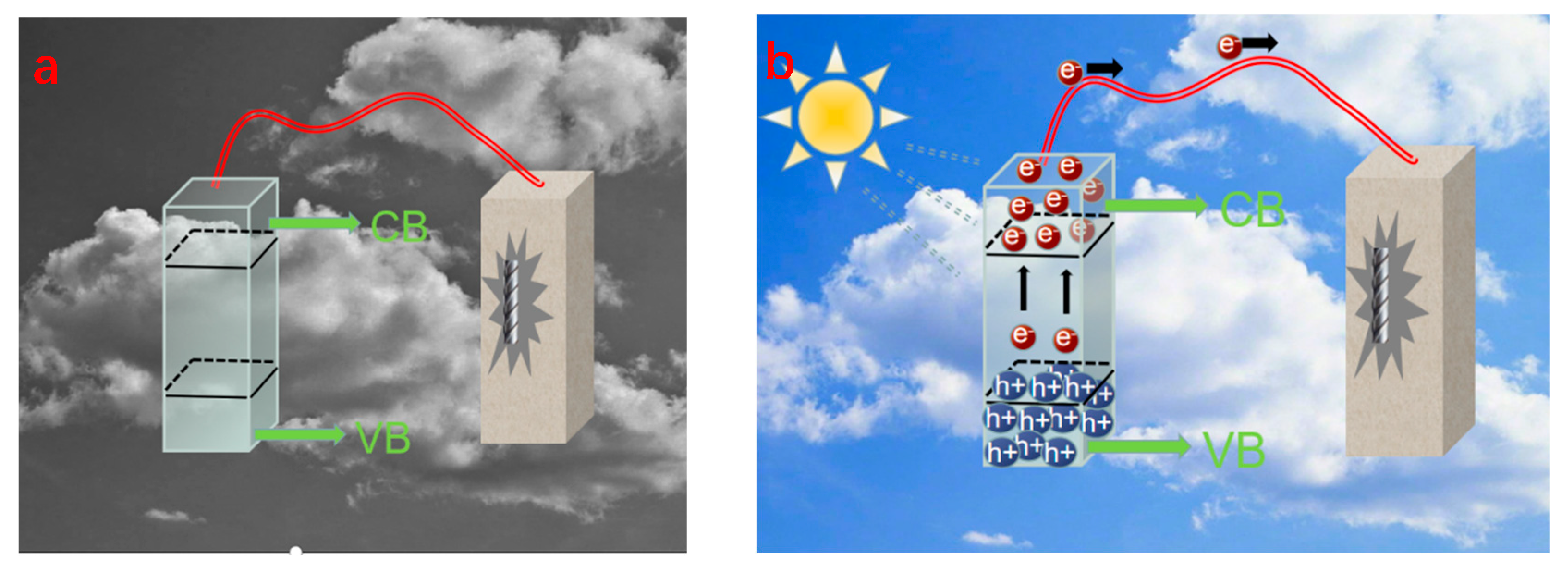
In 1995, Yuan et al. [31] used the sol–gel method to coat a pure copper sheet with a TiO2 film and found that the potential of TiO2/Cu in 0.3% NaCl solution under light was lower than that of the bare copper electrode, and the photoelectric effect of TiO2 effectively reduced the potential of the copper sheet and provided CP to inhibit corrosion; thus, the concept of photoelectrochemical CP was proposed. The theoretical basis of photochemical CP is the photoelectric effect of semiconductor materials (mostly n-type semiconductor materials). The semiconductor energy band is usually composed of a low-energy valence band (VB) filled with electrons and an empty high-energy conduction band (CB). There is a region between the valence band and the conduction band called the forbidden band; the size of the region is called the forbidden bandwidth (Eg), as shown in Figure 1a. The general Eg of semiconductor material is less than 3 eV when the surface is irradiated with a suitable wavelength of light, that is when the light energy . During semiconductor light absorption, VB electrons leap to the CB conduction band to produce negatively charged highly active electrons (e−). In the positively charged holes left by the movement of the VB electrons (h+) [32], when the n-type semiconductor material and the coupling of metal materials have a suitable potential match, the photogenerated electrons generated on the semiconductor material can be transferred to the coupled metal material. In this way, the semiconductor material plays the role of a sacrificial anode to provide electrons for the coupled metal, which is macroscopically expressed as a negative shift of the metal potential, thus playing the role of CP (Figure 1) [33].

Figure 1.
(a) CP schematic diagram of steel rebar; (b) CP schematic diagram of the current generated by the photogenerated system [33].
Semiconductor materials are the core of photoelectric CP. The chemical materials used are mainly wideband semiconductor materials such as TiO2, SrTiO3 [34], ZnO, etc. TiO2 is the most widely studied and applied photoelectric CP material, but a single TiO2, because of its ECB close to −0.29 V (vs. NHE), can only provide photoelectric CP for self-corrosion potential. It is more useful for some stainless steel and copper metals to provide photoelectrochemical CP; however, this CP effect is difficult to apply to some widely used metals (such as carbon steel and weathering steel) [35]. The single semiconductor photoanode made of a single semiconductor material often has weak light absorption performance in photocathode protection applications. It can only absorb ultraviolet light and a small amount of visible light (for example, SrTiO3 can only be excited by ultraviolet light), and the disadvantages involving lack of effective separation and tendency of combination pathway of the electron-hole make its photoelectrochemical performance not ideal, and its photocathode protection capacity is too dependent on light [36]; however, through the modification of single semiconductor material, compounding can improve its photoelectrochemical performance [37].
Li et al. [38] coupled SnIn4S8/TiO2 composite photoanode with Q253 carbon steel and found that the potential of Q235 carbon steel in 3.5 wt.% NaCl solution could reach −0.45 V (v.s. SCE), and SnIn4S8/TiO2 could provide efficient CP for Q235 carbon steel compared with pure TiO2. In 2002, Kato [39] found that SrTiO3 doped with Sb and Cr showed strong absorption in the visible region, with Eg down to 2.4 eV. Lu et al. [40] found that the M-S curves of the nano-TiO2 layer showed a positive slope (n-type nature), and the Co(OH)2 layer showed a negative slope (p-type nature) with positive and negative slopes, indicating the coexistence of n-type and p-type semiconductor properties. The formation of the pn junction electric field enhanced the migration of electrons and holes in opposite directions, resulting in a better separation of holes from electrons. Due to the pn junction electric field formation, the icorr of 304 stainless steel coupled with Co(OH)2/TiO2 was the highest under light conditions compared to pure TiO2, indicating that the Co(OH)2/TiO2 photoanode produces the highest number of photogenerated electrons and the highest hole–electron separation efficiency.
Guo et al. [41] modified ZnO films with polyaniline (PAN), and the currents of both ZnO films and ZnO/PANI composite films were very low (around 0.5 μA) under dark-state conditions. When simulating sunlight irradiation, the current of ZnO film increased by 7 μA, and that of ZnO/PANI composite film increased by 22 μA. The current increase in the ZnO/PANI composite film was significantly higher than that in the ZnO film, indicating that the ZnO film modified by PAN absorbed light more strongly. The CaIn2S4/TiO2 nanotube array heterojunction (NTA) photoanode prepared by Cui et al. [42] provided over 12 h of CP for 316 stainless steel in 3.5 wt.% NaCl solution, even in the dark state.
Graphitic phase carbon nitride (g-C3N4) is an emerging, inexpensive, non-metallic polymeric photoanode material that has broken the monopoly of traditional metal-semiconductor materials in the field of photoanodes. g-C3N4 has excellent wear, high temperature, and corrosion resistance properties and can be used as a coating to provide good physical protection for metals in the dark state [43]. However, the urgent problem that needs to be solved when using g-C3N4 for photochemical CP in the marine environment is the insufficient oxidation capacity of g-C3N4 photogenerated holes. g-C3N4 valence band potential is around 1.27 V (v.s.SHE), while the oxidation potential of water is 1.23 V (v.s.SHE); therefore, in the electrolyte system, where the photogenerated hole trapping agent is water (e.g., 3.5 wt.% NaCl solution), the anodic depolarization of photogenerated holes is difficult. Thus, in the photoelectrochemical CP process, it is necessary to add an appropriate amount of hole-trapping agents, such as S2- or some organic substances that can be easily oxidized in the electrolyte [44]. In addition, the g-C3N4 photoelectrochemical reaction has fewer active sites and lower electron mobility.
The sacrificial anode CP system does not require a power supply, has low driving voltage, and does not interfere with neighboring facilities. It also has good current dispersion ability, requires simple equipment, and generally does not require great technical investment. After the installation of the protection system, its operation requires almost no cost, only the occasional check of the potential or protection current. The system also has low protection voltage and no safety concerns. Therefore, sacrificial anode CP is widely used for the protection of ships, offshore equipment, underwater equipment, underground oil and gas pipelines, underground cables, seawater cooling systems, etc. It is also very suitable for the protection of concrete structures in the wave splash zone, tidal difference zone, and total immersion zone, which remain in wet conditions for a long time.
However, the sacrificial anode protection method has some drawbacks. (1) The protection current cannot be adjusted and may be under-protected or over-protected. Materials such as high-strength steel used in large quantities in marine environments have hydrogen embrittlement sensitivity [45], and the over-negative protection potential will easily lead to hydrogen precipitation and diffusion into the internal steel. This will reduce the mechanical properties of steel and may cause hydrogen cracking under the action of external high pressure and internal stress [46]. For this reason, the hydrogen embrittlement sensitivity of high-strength steel has been studied extensively at home and abroad, and it has been found that the protection potential of high-strength steel should not be greater than −0.870 V (vs. SCE); moreover, the protection current is limited by the resistivity of seawater [47]. (2) As for the sacrificial anode, the traditional anode metal smelting consumes a certain amount of non-ferrous metals that can cause serious atmosphere pollution, and the anode metal in service will produce a large number of metal ions in the marine environment, especially when its heavy metal ions will inevitably dissolve in seawater [48]. There is a need to regularly check and replace the metal anode; the design life is usually short, it is difficult to meet the requirements of long-term corrosion protection of marine engineering, and consumption can be accelerated because of the attachment exfoliation of marine organisms to the sacrificial anode [49]. Additionally, the design specifications of structural load-bearing will be increased, leading to additional construction costs for the total structure, and the uneven dissolution of the surface of the sacrificial anode produces local corrosion, which will cause more damage.
Although the light anode does not exhibit the above-mentioned disadvantages of the traditional sacrificial anode, the light anode has high cost, poor environmental stability, unstable electrochemical protection performance, and difficulty in long-term application. The conduction band potential of conductor material in a light anode is more negative than the potential of the coupling metal.
4. Applied Current CP
The applied current CP method is based on the principle of electrochemical electrolytic cells, using an external power supply to change the potential of the protected metal. The negative power supply is connected to the protected metal so that the potential of the protected metal is in a state lower than the surrounding environment. This allows it to become the cathode in the environment, which stops it from losing electrons and becoming corroded.
The applied current CP system is mainly composed of the protected metal, the auxiliary anode, the reference electrode, and the power supply to provide the protection current. The external power supply is an important part of applied current CP, and the more widely used external power supplies are rectifiers and constant potential meters [50]. Traditional applied current CP requires an external continuous power supply, which has the problems of energy consumption, waste of resources, and environmental pollution. Due to energy shortage and pollution, the demand for new green energy is becoming more and more urgent, and how to use green energy as a self-powered system to achieve impressive current CP has become a new research direction.
4.1. Temperature Difference Electricity Generation Power Supply Technology
Temperature difference electricity generation (TEG) is a technology based on the Seebeck effect of thermoelectric materials to convert heat into electricity. The p-type semiconductor material containing holes and the n-type semiconductor material containing electrons are connected at one end by a copper conductor to form a pn junction. Then, the two ends of the pn junction are connected to a heat source and a cold source, respectively, creating a temperature gradient across the pn junction. At this time, if a load resistor is added to form a closed circuit, a current can be measured in the system [51]. The temperature difference and output current generated by a single pn junction are very low; therefore, the TEG battery used for power generation is usually composed of multiple pn junction connections.
Generally speaking, the lower the temperature value, the more difficult it is to utilize the waste heat. However, TEG is able to utilize the waste heat with a temperature difference of several tens of degrees. The single group of TEG sheets made by Wu et al. [52] had an output power of 9.42 mW and an output voltage of 198.85 mV at a temperature difference of 16 °C. This makes it possible to utilize low-grade thermal energy, such as seawater, geothermal heat, industrial and agricultural waste heat, etc., to generate electricity that can then be used for the applied current CP in the above environments.
Li [53] used the greenhouse buried heating pipeline as the heat source and the soil as the cold source to verify the effectiveness of the TEG cell of bismuth telluride material for the CP of the buried pipeline. The pipeline potential was −0.51 V (v.s.CSE) when no CP was added and −0.933 V when CP was available, indicating that the CP device was effective and the pipeline was protected. In a 90d natural corrosion experiment, when the average corrosion rate of the pipeline was 0.0042 g·m−2·h−1 and the protection potential provided was −1.1 V, the degree of protection reached 92.79%.
Yao et al. [54] found that the internal resistance of the TEG unit did not change significantly with temperature difference, and the voltage fluctuation of the CP system was less than 0.2 V, which indicated that the TEG unit had high stability and could provide a long-term, stable protection current. An allotment of 3.5 wt.% NaCl was added to the concrete simulating liquid to simulate the corrosion of reinforcing steel in concrete under a Cl-erosion environment. When ΔT = 20 °C, and when two TEG units were in series (series voltage about 2.7 V), the protection potential of the reinforcement connected to it at 3d could reach about −0.77 V (v.s.SCE). Electrochemical noise analysis found that the average value of the noise potential of the reinforcement gradually shifted positively from −40 mV at the beginning to −24 mV. The noise resistance gradually became greater, indicating that the reinforcement entered a thermodynamic steady state from a corrosion state. It showed that the corrosion of reinforcing steel was inhibited after the CP current was applied, which provided an experimental reference for the use of temperature difference power generation for CP of reinforcing steel in offshore structures.
The output current of TEG is direct current, and the system has a simple structure with no moving parts and no noise; however, there are disadvantages, such as low power generation efficiency and short service life of the temperature difference components [55].
4.2. Power Supply Technology of Piezoelectric Generators
The piezoelectric effect reflects the coupling between the elastic and dielectric properties of a crystal and is divided into two types: positive piezoelectric effect and inverse piezoelectric effect. A piezoelectric nanogenerator (PENG) is based on the positive piezoelectric effect, using it to effectively collect the mechanical energy in the environment to convert it into electrical energy [56].
Wave energy is a widely distributed and high-quality energy source in the marine environment. Zhou et al. [57] designed and produced a floating wave-driven PENG using a single set of double crystal P5-1 piezoelectric chips to generate electricity, and the measured output current in the marine environment was eventually stabilized at 0.170 mA when the output voltage was set to 5.0 V (after rectification). The experiments showed that a PENG can use wave energy to achieve a self-sufficient power supply for low-power monitoring equipment at sea, and the device can also be used for array power generation.
Zhang et al. [58] tested a 3 cm long and 2.5 cm wide, 110 μm thick, polarized PVDF film with a vibration frequency of 3 Hz and measured an output voltage/current of 2.3 V/0.03 μA. The simulated accelerated corrosion experiment was carried out in an electrolyte containing NaHSO3 and NaNO3, and as the corrosion proceeded, the EIS analysis found that the carbon steel connected to the PVDF film CP system had a lower polarization potential. Macroscopically, only a small number of gray spots appeared on the surface of the carbon steel, with no obvious corrosion, while the control group showed serious corrosion, as seen in Figure 2. It is clear that the PVDF piezoelectric device-driven CP system can indeed protect the metal from corrosion.
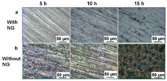
Figure 2.
Micrographs of the surfaces of carbon steel electrodes after simulated accelerated corrosion: (a) with and (b) without CP powered by the hybrid NG under the different durations (5, 10, and 15 h) [56].
A PENG has many advantages. Firstly, it can directly generate a suitable voltage, and secondly, unlike electrostatic induction, it does not require an initial voltage. In addition, there are no structural design limitations; therefore, theoretically, its mechanical damping coefficient can be designed to be smaller. PENGs also have the advantages of no electromagnetic interference and long-term piezoelectric oscillator generation [59]. One of the most important challenges in PENG design is the bandwidth of its sensed disturbance frequency. The narrow bandwidth makes it difficult to achieve an effective collection of broadband mechanical energy. The resonant frequency of the piezoelectric member can differ from the design value by 1–5% due to manufacturing and processing differences; therefore, the bandwidth of the piezoelectric member should cover a deviation range of at least 5% of its resonant frequency [60]. PENGs also have other challenges, such as the disturbance of output voltage by external frequencies, the size of the piezoelectric components, and the need for the output current to be connected to the rectifier circuit in order for it to be used as an alternating current. Wang [59] found that the PZT piezoelectric oscillator open-circuit voltage increased with the oscillator length and excitation frequency when the external disturbance frequency was close to the piezoelectric oscillator resonant frequency, a state which can be obtained under the maximum output voltage and actual sea conditions. If the impact force is too large, it could damage the piezoelectric oscillator, and if the force is too small, it will rebound; therefore, the piezoelectric oscillator should be reasonably designed to obtain the best output voltage and arranged to reduce the energy loss caused by friction [61]. PENGs also have disadvantages, such as the high cost of piezoelectric materials, low electromechanical conversion efficiency [62], high stiffness, poor response at low-frequency operating conditions [63], etc. The drawbacks of piezoelectric materials limit the development of PENGs, and there is an urgent need to develop new piezoelectric materials to enhance performance. Accordingly, the overview of bandwidth outputs of the PENG is demonstrated in Table 1.

Table 1.
Overview of bandwidth outputs of the PENG.
4.3. Triboelectric Nanogenerator Power Supply Technology
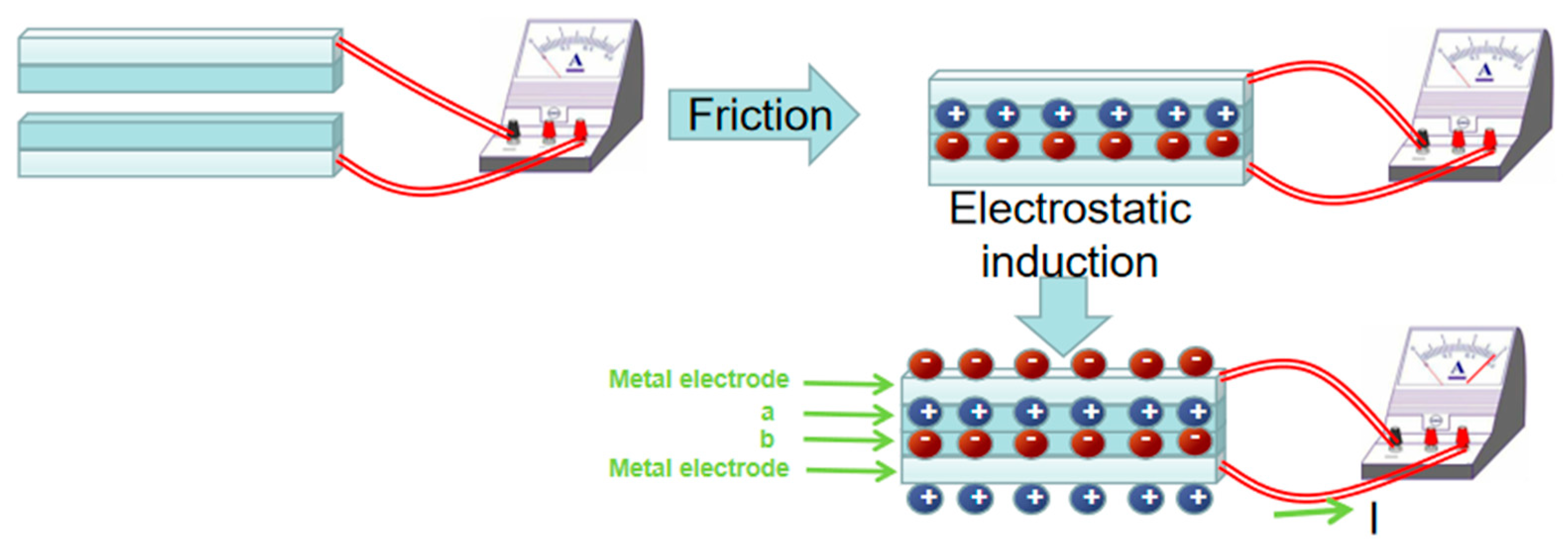
In 2012, Wang [73] first proposed the triboelectric nanogenerator (TENG) based on the principle of frictional electricity and electrostatic induction. Two friction electrode materials with different electronegativity (in Figure 3) generate induced charges when they are rubbed together. When the two materials are separated, the potential difference between them will be maintained for some time due to the insulating nature of the materials, at which time the metal electrode generates a positive charge due to electrostatic induction. This results in a positive charge flowing from the bottom metal electrode to the top metal electrode, which is manifested as a current in the external circuit. This new generator can be used to collect various forms of mechanical energy, such as human motion, mechanical vibration, rotation, wind, acoustic energy, raindrop and wave energy, etc., converting various mechanical motions into electrical signals [74].
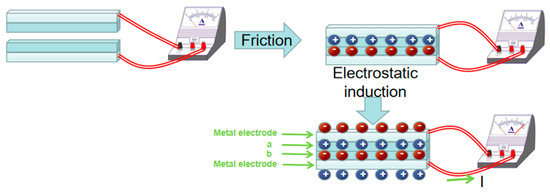
Figure 3.
Schematic diagram of generating principle of triboelectric nanogenerator.
Since its invention, the area power density of the TENG has increased from the initial 3.67 mW/m2 to 313 W/m2, and the volume power density has reached 490 mW/m3, with a conversion efficiency of 60%. From the perspective of energy matching, the output power of TENGs can theoretically meet the energy required for metal CP [36]. Zhang et al. [75] designed a PVC-GO film/Al single-electrode type TENG. The output voltage and short-circuit current were 118 V and 5.3 μA, respectively, and when the Q235 carbon steel was coupled to the negative electrode of the TENG, the corrosion potential of the carbon steel was reduced from −0.641 V (v.s. SCE) to −0.807 V (v.s. SCE) in 3.5 wt.% NaCl and the average corrosion rates were reduced by more than 65%.
The advantages of TENGs include the following: (1) high power generation voltage; (2) low cost; (3) good flexibility and flexible shape; (4) wide selection of friction electrode materials (a large number of electrode materials with large differences in electronegativity can be combined, and the surfaces modified by photolithography [76], etching [77], particle spraying [78], nanomaterials [79,80], etc., to adjust the surface dielectric constant of the material to enhance the frictional start effect and improve the output capacity of TENGs); (5) high conversion efficiency; and (6) sensitive perception of low-frequency, weak mechanical motion of vibration. Zhu et al. [81] found that the short-circuit current of the PDMS-ITO friction electrode TENG exceeded 130 μA, and the open-circuit voltage reached about 500 V at a vibration frequency of 1 Hz. The contact-separated TENG (CF-TENG) designed by Wang et al. [82] can still produce an open-circuit voltage of 0.54 V and a short-circuit current of 10 nA at amplitudes as low as 3.5 μm.
The output size of a TENG depends heavily on the external frequency (the output voltage increases with the frequency and vice versa [83]), and the output peak is unstable under practical conditions [36]. It is also sensitive to static electricity, stray capacitance, and temperature variations, again leading to unstable output [84]. The TENG’s internal impedance is large, the output current is alternating current, the average current output is small, and the power that can directly drive electronic devices is limited. The friction between the solids of the friction electrodes will lead to the generation and dissipation of heat, which will greatly limit the power generation efficiency of the TENG [78].
The applied current CP method has the following advantages: (1) it can be used to protect bare metal and metal structures with poor quality coatings; (2) it can be used in all electrolyte solutions that can conduct electricity; (3) it is useful for the protection of a structure’s internal devices; (4) it is suitable for the protection of the inner walls of storage tanks and buried tanks; (5) it can be used in a high resistivity environment; (6) it has adjustable potential output size, to avoid hydrogen cracking in the protected metal from over-protection; and (7) some studies have shown that after 5 years or more of applied current treatment if the protection current is interrupted due to the presence of chloride ions, steel can still maintain at least 24 months in a passive, uncorroded state [85,86].
Due to the challenges presented by the components of the applied current CP system, it has the following inherent drawbacks: (1) higher costs compared with the sacrificial anode method [87]; (2) the need for a continuous power supply from an external power source; (3) the possible production of stray currents; and (4) a low general number of auxiliary anodes, making it easy to cause over-protection near the auxiliary anode area and under-protection in areas experiencing serious shedding. The CP methods for steel rebars in the marine environment are summarized in Table 2.
Table 2.
Reviews in CP methods for reinforcing steel rebars.
5. Conclusions and Prospects
Seawater has a strong corrosive effect on steel rebars. If appropriate protective measures are taken, this effect can be reduced or even avoided in offshore structures. The cathodic protection method is an important anti-corrosion method for steel rebars in offshore structures, directly affecting the service life and safety of such structures. Through the development of new sacrificial anode materials and power supply systems, we can develop sacrificial anodes with low protection potential, slow corrosion rate, high current efficiency, high polarization efficiency, and long service life. The possibility exists for environmentally friendly sacrificial anodes, as well as green self-powered applied current cathodic protection systems with low energy loss, high conversion efficiency, stable and continuous work performance, and low cost. This will broaden the application of anti-corrosion technology to the protection of steel in complex, extreme environments, such as those with high temperature, low temperature, high pressure, and oil pollution, as well as acidic and alkaline corrosive environments.
Author Contributions
J.L., Conceptualization, Supervision, and Resources; Z.G., Z.X., X.Z. and J.L., Data acquiring, Formal analysis, and Methodology; Z.X., Z.G. and H.C., Funding acquisition, Investigation, and Project administration; J.L., X.Z. and Y.G., Validation, Visualization and Writing—original draft; X.Z., P.W., J.L. and H.S., Writing—review & editing. All authors have read and agreed to the published version of the manuscript.
Funding
This research was funded by Project from Sinohydro Bureau 5 Co., Ltd. (No. 20233702031475) and Shandong Natural Science Foundation (No. ZR2023ME011).
Institutional Review Board Statement
Not applicable for studies not involving humans or animals.
Informed Consent Statement
Informed consent was obtained from all subjects involved in the study.
Data Availability Statement
Data are contained within the article.
Acknowledgments
This study was financially supported by Project from Sinohydro Bureau 5 Co., Ltd. (No. DJTL-XM-2023-08), Shandong Natural Science Foundation (No. ZR2023ME011), and the National “111” project, and Shandong Gaofeng discipline project.
Conflicts of Interest
The authors declare that they have no competing financial interests. Author Zenghui Guo, Zhengwei Xiao and Hui Chen were all employed by the company Sinohydro Bureau 5 Co., Ltd. The remaining authors declare that the research was conducted in the absence of any commercial or financial relationships that could be construed as a potential conflict of interest.
References
- Xie, X. Study on the Photoelectric Chemical Cathodic Protection Properties of a New Type of Photocatalytic Materials in the Marine Environment. Master’s Thesis, Northeastern University, Boston, MA, USA, 2016. (In Chinese). [Google Scholar]
- Fan, W.T. Study of Corrosion Behavior of Fe3Al Interfundamental Compounds in Seawater. Master’s Thesis, Ocean University of China, Qingdao, China, 2007. (In Chinese). [Google Scholar]
- Blikharskyy, Y.; Selejdak, J.; Kopiika, N. Specifics of corrosion processes in thermally strengthened rebar. Case Stud. Constr. Mat. 2021, 22, 15–28. [Google Scholar] [CrossRef]
- Torbati-Sarraf, H.; Poursaee, A. Corrosion improvement of carbon steel in concrete environment through modification of steel microstructure. J. Mater. Civil. Eng. 2019, 31, 04019042. [Google Scholar] [CrossRef]
- Zheng, K.F.; Zhang, Y.; Heng, J.L.; Wang, Y.W. High strength weathering steel and its application and prospect in bridge engineering. J. Harbin Instit. Technol. 2020, 52, 1–10. (In Chinese) [Google Scholar]
- Wang, B.; Wei, S.C.; Huang, W.; Wang, Y.J.; Liang, Y.; Guo, L.; Chen, X.H.; Pan, F.S.; Xu, B.S. Status and progress on anticorrosive coatings for marine application. Mater. Protect 2019, 52, 132–138. (In Chinese) [Google Scholar]
- Wang, Y.F.; Chen, L. On the mechanism of action and application development of corrosion inhibitors. Tech. Econom. Gui 2020, 28, 128–129. (In Chinese) [Google Scholar]
- Li, M.F.; Jia, Z.H. Anti-corrosion design of steel structures. Corros. Protect 2005, 26, 355–357. (In Chinese) [Google Scholar]
- Zhou, D.Q. Application of cathodic protection to steel structure in sea port engineering. China Harbor Eng. 2000, 3, 28–32. (In Chinese) [Google Scholar] [CrossRef]
- Hou, J.; Zhang, Q. Corrosion behavior of high potential Mg-Mn sacrificial anode. Spec. Cast. Nonfer Alloy 2012, 11, 126–131. (In Chinese) [Google Scholar] [CrossRef]
- Shamsudin, S.R.; Rahmat, A.; Isa, M.C.; Derman, M.N.; Daud, A.R. Electrochemical corrosion behaviour of Mg-(Ca,Mn) sacrificial anodes. Adv. Mater. Res. 2013, 95, 530–534. [Google Scholar] [CrossRef]
- Pardo, A.; Merino, M.C.; Coy, A.E.; Viejo, F.; Arrabal, R.; Feliu, S., Jr. Influence of microstructure and composition on the corrosion behaviour of Mg/Al alloys in chloride media. Electrochim. Acta 2008, 53, 7890–7902. [Google Scholar] [CrossRef]
- Wang, W. Research on cathodic protection by sacrificial anodes of copper alloy pipes in seawater environment for shipboard. Dev. Appl. Mater. 2016, 31, 93–98. (In Chinese) [Google Scholar]
- Song, Y.H.; Guo, Z.C.; Fan, A.M.; Long, J.M. Current state of research on sacrificial anode materials. Corros. Sci. Prot. Technol. 2004, 16, 24–28. (In Chinese) [Google Scholar]
- Wang, Y.; Guo, C.; Kong, D.C.; Zhao, Z.J.; Wang, L.; Dong, C.F. Microstructures and corrosion failure analysis of zinc anode. Powder Metall. 2018, 36, 348–354. (In Chinese) [Google Scholar]
- Ashworth, V.; Googan, C.G.; Scantlebury, J.D. Intergranular dissolution of zinc alloy sacrificial anodes in sea water at elevated temperature. J. Br. Corros. 2013, 14, 227–236. [Google Scholar] [CrossRef]
- Han, W. Effect of Environmental Temperature on Performance of Zinc Alloys for Sacrificial Anode and Study of Modification of Alloys. Master’s Thesis, Xi’an University of Architecture and Technology, Xi’an, China, 2011. (In Chinese). [Google Scholar]
- Cao, L. The Cathodic Protective Performance and Application of Sacrificial Anode in Underground Water and Seawater Environment. Master’s Thesis, Liaoning Normal University, Dalian, China, 2015. (In Chinese). [Google Scholar]
- Gao, X.Z. Application of sacrificial anode protection method in anti-corrosion of reinforced concrete members of sea-crossing bridges. Fujian Constr. Sci. Technol. 2019, 3, 14–17. (In Chinese) [Google Scholar]
- Wang, H.T.; Xu, S.; Wang, H. Research and application of sacrificial anode materials for special working conditions. In Proceedings of the 2020 Seventh Conference on Marine Materials and Corrosion Protection and 2020 First Conference on Reinforced Concrete Durability and Facility Service Safety, Wuxi, China, 7 November 2020. [Google Scholar]
- Zhou, Y.H.; Zheng, L.M.; Guo, X.H.; Han, X.J. Electrochemical corrosion behavior of industrial pure aluminum in simulated seawater. J. Harbin Instit. Technol. 2009, 41, 58–63. (In Chinese) [Google Scholar]
- Muazu, A.; Aliyu, Y.S.; Abdulwahab, M.; Popoola, A. Sacrificial anode stability and polarization potential variation in a ternary Al-xZn-xMg alloy in a seawater-marine environment. J. Mar. Sci. Appl. 2016, 10, 229–234. [Google Scholar] [CrossRef]
- Khan, B.; Rosli, M.U.; Jahidi, H.; Ishak, M.I.; Zakaria, M.S.; Jamalludin, M.R.; Khor, C.Y.; Faizal, W.M.; Rahim, W.M.; Nawi, M.A.M. Effect of zinc addition on the performance of aluminum alloy sacrificial anode for marine application. In AIP Conference Proceedings; AIP Publishing LLC: New York, NY, USA, 2017; p. 020074. [Google Scholar]
- Sun, M.X.; Ma, L.; Zhang, H.B.; Yan, Y.G.; Liu, S.T. Research progress in aluminum alloy sacrificial anode materials. Equip. Environ. Eng. 2018, 15, 9–13. (In Chinese) [Google Scholar]
- Zhang, G.Q.; Qian, S.C.; Zhang, H.B.; Liang, J.; Guo, W.M.; Xing, S.H.; Fan, L. Performance of aluminum sacrificial anodes in deep sea. Equip. Environ. Eng. 2011, 16, 33–37. (In Chinese) [Google Scholar]
- Huang, J.F.; Song, G.L. Hydrogen evolution, efficiency and exacerbated galvanic corrosion damage of magnesium alloy anode. J. Mater. Eng. 2021, 49, 48–56. (In Chinese) [Google Scholar]
- Su, P.; Du, C.W.; Li, X.G.; Chen, X. Process on the investigation of AZ63 Mg-based alloy sacrificial anode. Equip. Environ. Eng. 2007, 4, 101–104+109. (In Chinese) [Google Scholar]
- Liu, H. Corrosion and Electrochemical Performance and Mechanism of AZ91E Magnesium Alloy in Simulated Seawater. Master’s Thesis, Shandong University of Science and Technology, Qingdao, China, 2020. (In Chinese). [Google Scholar]
- Lei, B.; Hu, S.N.; Wan, W.T.; Niu, J.M.; Lu, Y.F.; Hu, K.F. Sacrificial anode CP of copper seawater cooling equipment for marine use. Mater. Protect 2016, 49, 27–30. (In Chinese) [Google Scholar]
- Prasad, N.K.; Pathak, A.S.; Kundu, S.; Mondal, K. Novel hybrid sacrificial anodes based on high phosphorus pig iron and Zn. Corros. Sci. 2021, 189, 109616. [Google Scholar] [CrossRef]
- Yuan, J.N. Characterization of sol-gel-derived TiO2 coatings and their photoeffects on copper substrates. J. Electrochem. Soc. 1995, 142, 3444–3446. [Google Scholar] [CrossRef]
- Hong, H.X. Fabrication of Ag+ Doping Titania Tilm on 304 Stainless Steel Substrates and Anti-corrosion Properties Research. Master’s Thesis, Ocean University of China, Qingdao, China, 2010. (In Chinese). [Google Scholar]
- Liu, X.C.; Li, H.T.; Jing, J.P.; Sun, M.M.; Chen, Z.Y.; Sun, M.X.; Hou, J.N. Principle and research progress of photoelectrochemical cathodic protection. Equip. Environ. Eng. 2017, 14, 1–7. (In Chinese) [Google Scholar]
- Ohko, Y.; Saitoh, S.; Tatsuma, T.; Fujishima, A. Photoelectrochemical anticorrosion effect of SrTiO3 for carbon steel. Electrochem. Solid-ST 2002, 5, 67–75. [Google Scholar] [CrossRef]
- Zhang, X.F.; Li, M.Y.; Kong, L.F.; Wang, M.; Yan, L.; Xiao, F.J. Research progress in metal photoelectrochemical cathodic protection materials and its anticorrosion function realization. Surf. Technol. 2021, 50, 128–140. (In Chinese) [Google Scholar]
- Guan, Z.C.; Zhao, J.Z.; Guo, W.X.; Du, R.G.; Lin, C.J. Research progresses in “green” electrochemical CP. J. Xiamen Univ. (Nat. Sci.) 2020, 59, 767–777. (In Chinese) [Google Scholar]
- Mohsen, M.M.; Majid, M.; Yousef, G.; Masoud, A. Photoelectrochemical cathodic protection of stainless steel using W- and Cr-doped/codoped TiO2 nanotube thin film photoanodes. J. Electrochem. Soc. 2021, 168, 081504. [Google Scholar]
- Li, H.; Song, W.; Cui, X.; Li, Y.; Hou, B.; Cheng, L.; Zhang, P. Preparation of SnIn4S8/TiO2 nanotube photoanode and its photocathodic protection for Q235 carbon steel under visible light. Nanoscale Res. Lett. 2021, 16, 10–21. [Google Scholar] [CrossRef]
- Kato, H.; Kudo, A. Visible-light-response and photocatalytic activities of TiO2 and SrTiO3 photocatalysts codoped with antimony and chromium. J. Phys. Chem. B 2002, 106, 5029–5034. [Google Scholar] [CrossRef]
- Lu, X.; Liu, L.; Ge, J.; Cui, Y.; Wang, F. Morphology controlled synthesis of Co(OH)2/TiO2 p-n heterojunction photoelectrodes for efficient photo CP of 304 stainless steel. Appl. Surf. Sci. 2021, 537, 148002. [Google Scholar] [CrossRef]
- Guo, X.B.; Huang, J.J.; Li, W.F.; Tian, Y.X.; Shen, J.Y. Photogenerated CP of polyaniline modified nano-ZnO films. Chem. Ind. Eng. Prog. 2018, 323, 239–244. (In Chinese) [Google Scholar]
- Cui, X.; Li, H.; Yang, Z.; Li, Y.; Zhang, P.; Zheng, Z.; Wang, Y.; Li, J.; Zhang, X. A novel CaIn2S4/TiO2 NTAs heterojunction photoanode for highly efficient photoCP performance of 316 SS under visible light. Nanotechnology 2021, 32, 395702. [Google Scholar] [CrossRef]
- Jing, J.P. Study on the Photoelectrochemical CP Performance of Modified Graphitic Carbon Nitride. Master’s Thesis, University of Chinese Academy of Sciences, Beijing, China, 2018. (In Chinese). [Google Scholar]
- Bu, Y.Y.; Chen, Z.Y.; Sun, M.M.; Zhang, X.Y. Application of carbon nitride materials in the field of photoelectrochemical cathodic protection. In Abstracts Collection of 2014 National Conference on Corrosion Electrochemistry and Test Methods, Proceedings of the 2014 National Conference on Corrosion Electrochemistry and Test Methods, Harbin, China, 21 July 2014; Corrosion Electrochemistry and Test Methods Committee of the Chinese Society of Corrosion and Protection (CSCP): Xiamen, China, 2014. [Google Scholar]
- Briottet, L.; Batisse, R.; de Dinechin, G.; Langlois, P.; Thiers, L. Recommendations on X80 steel for the design of hydrogen gas transmission pipelines. Int. J. Hydrog. Energy 2012, 37, 9423–9430. [Google Scholar] [CrossRef]
- Wen, L.J. Effects of Protection Potential on Cathodic Process and Mechanical Properties of Typical Steels in Marine Environment. Master’s Thesis, Tianjin University, Tianjin, China, 2014. (In Chinese). [Google Scholar]
- Zhang, R.; Jiang, Y.N. An introduction to the application of sacrificial anode protection method in the corrosion protection of steel pipe piles. Met. Sci. Technol. 2016, 26, 150–157. (In Chinese) [Google Scholar]
- Li, H.; Chen, Y.L.; He, H.L.; Han, B.; Li, X.Y.; Xu, B.; Liao, Z.W.; Yin, P.F.; Li, J.M.; Zheng, Z.J. The effect of distribution of auxiliary anode for Jacket’s cathode protect electric potential. Total Corros. Contr. 2021, 35, 63–70. (In Chinese) [Google Scholar]
- Sun, C.X. Study on the Effect of Simulated Fouling Biological Attachment on the Corrosion Performance of Zn Anodes. Master’s Thesis, Yantai University, Yantai, China, 2015. (In Chinese). [Google Scholar]
- Tian, D.L. The Design of a Numeric-Control High Frequency Switching Mode Power Supply Potentiostat in Cathodic Protection. Master’s Thesis, Ocean University of China, Qingdao, China, 2009. (In Chinese). [Google Scholar]
- Liang, Q.Y. Research of Concentration Solar Thermoelectric Generation Key Technology and Thermoelectric Performance Mechanism. Ph.D. Thesis, Northeast Agricultural University, Harbin, China, 2016. (In Chinese). [Google Scholar]
- Wu, Z.D.; Zhang, H.B.; Feng, Y.C.; Cai, Y.J.; Bao, L. Design of sensor self-power system based on thermoelectric power generation. Res. Explor. Lab. 2020, 39, 67–70. (In Chinese) [Google Scholar]
- Li, X.R. Improvement of Cathodic Protection of Greenhouse Buried Heat-Supply Pipeline Based on Thermoelectric Generation. Master’s Thesis, Northeast Agricultural University, Harbin, China, 2019. (In Chinese). [Google Scholar]
- Yao, W.; Xia, Q.; Zuo, J.Q. Cathodic protection of reinforcing steel in simulated concrete pore solution based on thermoelectric generation. J. Build. Mater. 2015, 18, 76–81. (In Chinese) [Google Scholar]
- Zhao, J.Y.; Zhu, D.S.; Zhou, Z.G.; Wang, C.H.; Chen, H. Research progress of thermoelectric power generation. Chin. J. Power Source 2010, 34, 310–313. (In Chinese) [Google Scholar]
- Wei, X. Study on Preparation of Nanosize PZT Powders and Piezoelectric Sensing Performances of PZT/CNT/cement Composites. Master’s Thesis, Qingdao University of Technology, Qingdao, China, 2014. (In Chinese). [Google Scholar]
- Zhou, Y.; Jin, X.; Fang, L.Y.; Shen, C.N.; Su, G. Marine self-contained wave energy piezoelectric power generator. Phys. Experim Coll. 2020, 33, 86–90. (In Chinese) [Google Scholar]
- Zhang, H.L.; Zhang, S.J.; Yao, G.; Huang, Z.L.; Xie, Y.H.; Sun, Y.J.; Yang, W.Q.; Zheng, C.H.; Lin, Y. Simultaneously harvesting thermal and mechanical energies based on flexible hybrid nanogenerator for self-powered cathodic protection. ACS Appl. Mater. Interf. 2015, 7, 28142–28147. [Google Scholar] [CrossRef] [PubMed]
- Wang, J.L. Research of Vibration Generaying Device Based on Piezoelectric Material. Master’s Thesis, Jiangsu University, Zhenjiang, China, 2010. (In Chinese). [Google Scholar]
- O’Keeffe, R.; Jackson, N.; Waldron, F.; O’Niell, M.; Mathewson, A. Investigation into modelling power output for MEMS energy harvesting devices using COMSOL MultiphysicsR. In Proceedings of the 14th International Conference on Thermal, Mechanical and Multi-Physics Simulation and Experiments in Microelectronics and Microsystems (EuroSimE), Wroclaw, Poland, 14–17 April 2013. [Google Scholar]
- Zhang, Y.L.; Lin, Z. Advances in technology of ocean wave energy converters using piezoelectric materials. In Proceedings of the Third Symposium of the Ocean, Energy Specialized Committee of the Chinese Renewable Energy Society, Qingdao, China, 15 August 2020. [Google Scholar]
- Ouyang, J.Y.; Gong, X.J.; Yan, Z.L.; Zhang, T.C. Development of novel ocean wave piezoelectric power generation device. Hydropower New Energy 2017, 8, 75–78. (In Chinese) [Google Scholar]
- Li, H.N. Research on Flexible Piezoelectric Power Generation Device under Wave Action. Master’s Thesis, Qingdao University, Qingdao, China, 2020. (In Chinese). [Google Scholar]
- Luo, C.X.; Qin, M.Z. A 3×n element piezoelectric vibration generator with low frequency and wide bandwidth exploiting modes separation technique. Acta Electron. Sin. 2020, 48, 554–560. (In Chinese) [Google Scholar]
- Qi, S.; Shuttleworth, R.; Oyadiji, S.O.; Wright, J. Design of a multiresonant beam for broadband piezoelectric energy harvesting. Smart Mater. Struct. 2010, 19, 25331. [Google Scholar] [CrossRef]
- Salem, M.S.; Ahmed, S.; Shaker, A.; Alshammari, T.A.; Al-Dhlan, K.A.; Alanazi, A.; Saeed, A.; Abouelatta, M. Bandwidth broadening of piezoelectric energy harvesters using arrays of a proposed piezoelectric cantilever structure. Micromachines 2021, 12, 973. [Google Scholar] [CrossRef]
- Eichhorn, C.; Tchagsim, R.; Wilhelm, N.; Woias, P. A smart and self-sufficient frequency tunable vibration energy harvester. J. Micromech. Microeng. 2011, 21, 113248. [Google Scholar] [CrossRef]
- Peters, C.; Maurath, D.; Schock, W.; Manoli, Y. Novel electrically tunable mechanical resonator for energy harvesting. In Proceedings of the PowerMEMS 2008+ microEMS2008, Sendai, Japan, 9–12 November 2008. [Google Scholar]
- Fu, H.; Yeatman, E.M. Rotational energy harvesting using bi-stability and frequency up-conversion for low-power sensing applications: Theoretical modelling and experimental validation. Mech. Syst. Signal Process. 2018, 125, 229–244. [Google Scholar] [CrossRef]
- Yang, Z.; Zu, J. A magnet-induced buckled-beam piezoelectric generator for wideband vibration-based energy harvesting. J. Intel. Mater. Syst. Str. 2014, 25, 1890–1901. [Google Scholar]
- Hajati, A.; Kim, S.G. Ultra-wide bandwidth piezoelectric energy harvesting. Appl. Phys. Lett. 2011, 99, 175–202. [Google Scholar] [CrossRef]
- Dhote, S.; Li, H.T.; Yang, Z.B. Multi-frequency responses of compliant orthoplanar spring designs for widening the bandwidth of piezoelectric energy harvesters. Inter. J. Mech. Sci. 2019, 157, 684–691. [Google Scholar] [CrossRef]
- Fan, F.R.; Tian, Z.Q.; Wang, Z.L. Flexible triboelectric generator. Nano Energy 2012, 11, 328–334. [Google Scholar] [CrossRef]
- Su, Y.J. The Study of Design, Preparation and Applications of Triboelectric Nanogenerators. Ph.D. Thesis, University of Electronic Science and Technology of China, Chengdu, China, 2015. (In Chinese). [Google Scholar]
- Wang, C.C.; Chang, C.Y. Enhanced output performance and stability of triboelectric nanogenerators by employing silane-based self-assembled monolayers. J. Mater. Chem. C 2020, 8, 4542–4548. [Google Scholar] [CrossRef]
- Mule, A.R.; Dudem, B.; Yu, J.S. High-performance and cost-effective triboelectric nanogenerators by sandpaper-assisted micropatterned polytetrafluoroethylene. Energy 2018, 165, 223–235. [Google Scholar] [CrossRef]
- Wang, M.M. Properties and Preparation of Biocompatible Triboelectric Nanogenerator. Master’s Thesis, Tianjin University of Technology, Tianjin, China, 2017. (In Chinese). [Google Scholar]
- Han, C.B.; Wang, M.Q.; Huang, J.H.; Zheng, J.Y.; Zhao, W.K.; Zhang, H.; Zhang, Y.Z. Research progress of triboelectric generator and its potential application. J. Beijing Univ. Technol. 2020, 46, 1103–1127. (In Chinese) [Google Scholar]
- Guang, Z.; Zong-Hong, L.; Qingshen, J.; Peng, B.; Caofeng, P.; Ya, Y.; Yusheng, Z.; Lin, W.Z. Toward large-scale energy harvesting by a nanoparticle-enhanced triboelectric nanogenerator. Nano Lett. 2013, 13, 3236–3245. [Google Scholar]
- Rana, S.M.S.; Rahman, M.T.; Sharma, S.; Salauddin, M.; Yoon, S.H.; Park, C.; Maharjan, P.; Bhatta, T.; Park, J.Y. Cation functionalized nylon composite nanofibrous mat as a highly positive friction layer for robust, high output triboelectric nanogenerators and self-powered sensors. Nano Energy 2021, 88, 106300. [Google Scholar] [CrossRef]
- Zhu, H.R.; Tang, W.; Gao, C.Z.; Han, Y.; Li, T.; Cao, X.; Wang, Z.L. Self-powered metal surface anti-corrosion protection using energy harvested from rain drops and wind. Nano Energy 2014, 14, 193–200. [Google Scholar] [CrossRef]
- Wang, S.; Niu, S.; Yang, J.; Lin, L.; Wang, Z.L. Quantitative measurements of vibration amplitude using a contact-mode freestanding triboelectric nanogenerator. ACS Nano 2014, 8, 12004–12013. [Google Scholar] [CrossRef]
- Wu, Y.S.; Liu, Q.; Cao, J.; Li Ki Cheng, G.G.; Zhang, Z.Q.; Ding, J.N.; Jiang, S.Y. Design and output performance of a friction nanogenerator for collecting vibration energy. Acta Phys. Sin. 2019, 68, 19–26. (In Chinese) [Google Scholar] [CrossRef]
- Persano, L.; Dagdeviren, C.; Su, Y.W.; Zhang, Y.H.; Girardo, S.; Pisignano, D.; Huang, Y.G.; Rogers, J.A. High performance piezoelectric devices based on aligned arrays of nanofibers of poly(vinylidenefluoride-co-trifluoroethylene). Nat. Comm. 2013, 4, 1633–1641. [Google Scholar] [CrossRef] [PubMed]
- Christodoulou, C.; Glass, G.; Webb, J.; Austin, S.; Goodier, C. Assessing the long term benefits of impressed current cathodic protection. Corros. Sci. 2010, 52, 2523–2537. [Google Scholar] [CrossRef]
- Law, D.W.; Nicholls, P.; Christodoulou, C. Residual protection of steel following suspension of impressed current cathodic protection system on a wharf structure. Constr. Build. Mater. 2019, 210, 48–55. [Google Scholar] [CrossRef]
- Zhang, Y.Y.; Li, Y.; Ni, H. The principle and application of cathodic protection. Total Corros. Contr. 2015, 29, 22–24. (In Chinese) [Google Scholar]

Disclaimer/Publisher’s Note: The statements, opinions and data contained in all publications are solely those of the individual author(s) and contributor(s) and not of MDPI and/or the editor(s). MDPI and/or the editor(s) disclaim responsibility for any injury to people or property resulting from any ideas, methods, instructions or products referred to in the content. |
© 2024 by the authors. Licensee MDPI, Basel, Switzerland. This article is an open access article distributed under the terms and conditions of the Creative Commons Attribution (CC BY) license (https://creativecommons.org/licenses/by/4.0/).