Article

Size-Dependent Mechanical Properties and Excavation Responses of Basalt with Hidden Cracks at Baihetan Hydropower Station through DFN–FDEM Modeling

1
Key Laboratory of Geotechnical Mechanics and Engineering of Ministry of Water Resources, Changjiang River Scientific Research Institute, Wuhan 430010, China
2
State Key Laboratory of Geomechanics and Geotechnical Engineering, Institute of Rock and Soil Mechanics, Chinese Academy of Sciences, Wuhan 430071, China
3
School of Civil and Hydraulic Engineering, Huazhong University of Science and Technology, Wuhan 430074, China
*
Author to whom correspondence should be addressed.
Appl. Sci. 2024, 14(19), 9069; https://doi.org/10.3390/app14199069
Submission received: 30 July 2024 / Revised: 18 September 2024 / Accepted: 20 September 2024 / Published: 8 October 2024
(This article belongs to the Special Issue Advances in Failure Mechanism and Numerical Methods for Geomaterials)

Abstract

:
Basalt is an important geotechnical material for engineering construction in Southwest China. However, it has complicated structural features due to its special origin, particularly the widespread occurrence of hidden cracks. Such discontinuities significantly affect the mechanical properties and engineering stability of basalt, and related research is lacking and unsystematic. In this work, taking the underground caverns in the Baihetan Hydropower Station as the engineering background, the size-dependent mechanical behaviors and excavation responses of basalt with hidden cracks were systematically explored based on a synthetic rock mass (SRM) model combining the finite-discrete element method (FDEM) and discrete fracture network (DFN) method. The results showed that: (1) The DFN–FDEM model generated based on the statistical characteristics of the geometric parameters of hidden cracks can consider the real structural characteristics of basalt, whereby the mechanical behaviors found in laboratory tests and at the engineering site could be exactly reproduced. (2) The representative elementary volume (REV) size of basalt blocks containing hidden cracks was 0.5 m, and the mechanical properties obtained at this size were considered equivalent continuum properties. With an increase in the sample dimensions, the mechanical properties reflected in the stress–strain curves changed from elastic–brittle to elastic–plastic or ductile, the strength failure criterion changed from linear to nonlinear, and the failure modes changed from fragmentation failure to local structure-controlled failure and then to splitting failure. (3) The surrounding rock mass near the excavation face of underground caverns typically showed a spalling failure mode, mainly affected by the complex structural characteristics and high in situ stresses, i.e., a tensile fracture mechanism characterized by stress–structure coupling. The research findings not only shed new light on the failure mechanisms and size-dependent mechanical behaviors of hard brittle rocks represented by basalt but also further enrich the basic theory and technical methods for multi-scale analyses in geotechnical engineering, which could provide a reference for the design optimization, construction scheme formulation, and disaster prevention of deep engineering projects.

1. Introduction

With the development of the National “Western Development” strategy in China, several rock projects, such as in the fields of transportation, mining, and water conservancy, are ongoing. Some of the main challenges hindering the progress of these projects include hard rock failure and disasters induced under high in situ stresses, which are prominent and unavoidable [1,2,3,4]. Discontinuities of various levels are formed inside a rock, which is a natural heterogeneous geological material, ranging from primary defects, such as microcracks and micro-holes at the meso-scale; to hard structural planes, such as beddings, cracks, and joints at the macro-scale; and even to weak structural planes with a length of several hundred meters, such as dislocation zones and faults. In other words, the discontinuities have hierarchies and scales, remarkably influencing the mechanical properties and engineering stability of rocks. Brittle rock failure is a continuous fracture evolution process that constantly involves the closure, initiation, propagation, and coalescence of defects under various loads, eventually leading to material failure [5,6]. Therefore, the exploration of the failure process and the evolution laws of the mechanical properties of hard rocks is important to thoroughly reveal the development mechanism of disasters, accurately guide warning systems, and effectively reduce the risk of high-stress-induced disasters.
The mechanical properties of rocks exhibit a significant size effect due to the presence of discontinuities at different levels. Relevant research methods mainly include tests, theoretical analyses, empirical estimation, and numerical simulations, among which the synthetic rock mass (SRM) method, which combines conventional numerical models representing an intact matrix and a discrete fracture network (DFN) model representing discontinuities, has been the most commonly used for multiscale mechanical analyses in geotechnical engineering [7,8]. These numerical simulation methods can be broadly divided into continuous methods, such as the finite difference method (FDM), finite element method (FEM), and boundary element method (BEM); discontinuous methods, such as the discrete element method (DEM) and discontinuous deformation analysis (DDA); and hybrid methods, such as the finite-discrete element method (FDEM). In particular, the FDEM has the advantages of both discontinuous and continuous numerical methods, owing to which it can effectively simulate the gradual transformation process of materials from continuous to discontinuous, representing an important simulation technology for particle fracture, fragmentation, and interaction in brittle geomaterials [9,10,11,12]. Based on the SRM model combining a DFN model with multiple numerical software packages, such as the universal distinct element code (UDEC) and particle flow code (PFC), the size effect of the mechanical properties of rocks under different stress conditions, such as uniaxial compression, triaxial compression, Brazilian disc splitting, and direct shear, has been systematically investigated, yielding the corresponding equivalent mechanical parameters and representative elementary volume (REV) [13,14,15,16,17,18].
An accurate understanding of the fracture evolution and failure mechanisms of hard brittle rocks is important to ensure the safety of construction projects in deep underground engineering. Therefore, extensive studies have been conducted to explore the fracture problems of hard rocks, with the most complete ones being tests, field monitoring, and numerical simulation of the fracture problems of marble in the deep-buried diversion tunnel of Jinping II Hydropower Station and Lac du Bonnet (LdB) granite in the Underground Research Laboratory (URL) of the Atomic Energy of Canada Limited (AECL) [19,20,21,22]. In underground engineering, excavation through hard rocks under high-stress conditions breaks the original stress balance state, resulting in a brittle failure in the surrounding rock mass near tunnel faces, mainly manifesting as tensile fracture. With continuous excavation advancement and stress adjustment, the fracture of the surrounding rock mass develops from the surface to the inside, mainly exhibiting a shear failure mechanism. The fracture problem in hard rock underground engineering can be broadly divided into two categories: static fracture (e.g., spalling and slabbing) and dynamic fracture (e.g., rock bursts). The main influencing factors include geological conditions and engineering factors. Among them, in situ stresses and discontinuities play a decisive role, according to which the failure modes of surrounding rock mass can be classified as structure control type, stress–structure control type, and stress control type [23,24]. The excavation of rocks in underground engineering significantly disturbs the rock mass medium, leading to the formation of a generalized excavation-affected zone near the tunnel face, which can be typically classified into three sub-regions: an excavation disturbed zone (EdZ) in the inner area, an excavation damage zone (EDZ) in the middle area, and a highly excavation damage zone (HDZ) on the surface of the cavern [25,26].
Basalt, which is a typical volcanic rock, is a significant geological environment material for engineering construction in Southwest China, particularly in terms of the diversity and complexities of its mechanics at Baihetan Hydropower Station [27,28]. Liu et al. and Bubeck et al. systematically studied the influences of meso-defects, such as amygdales, holes, and hidden cracks, on the macro-mechanical properties of basalt, including its deformation, strength, and failure characteristics, through laboratory tests, numerical simulations, and statistical analyses. In addition, the size effect of the geometry and mechanics of basalt containing meso-defects has been explored [29,30,31,32,33]. Zhang et al. [34] obtained the distribution characteristics of discontinuities in basalt found in the dam site near Baihetan Hydropower Station by conducting a field data statistical analysis, through which the corresponding DFN model was established to analyze the geometric size effect. The fracture evolution laws, failure modes, and deformation characteristics of the surrounding rock mass during the underground cavern excavation at Baihetan Hydropower Station were systematically analyzed by numerical simulation, geological survey, and field monitoring, thoroughly revealing the failure mechanisms [35,36]. In addition, the size effect, anisotropy effect, unloading effect, and constitutive model of columnar-jointed basalt with special structural characteristics have been explored through various methods [37,38].
The multiscale mechanical properties and failure mechanisms of geotechnical materials with complex structures have been challenging issues in the field of geotechnical engineering. On the one hand, due to the complexity of the structural characteristics of natural rocks, the results of rock samples with small sizes in laboratory experiments may be different from those obtained through in situ tests, while in situ tests on samples with large sizes have disadvantages such as difficult testing, high cost, data dispersion, and poor reliability. On the other hand, the mechanical behaviors of basalt are mainly studied through conventional laboratory tests, field monitoring, and numerical simulation. To a certain extent, the complex structural characteristics of this type of geotechnical material are neglected; there is a lack of systematic and sufficient understanding of the effects of hidden cracks in basalt on its mechanical properties, making it difficult to accurately grasp its true mechanical behaviors and fracture mechanisms. In addition, the conventional size effect analyses are often only aimed at jointed rock mass with certain structural characteristics to obtain the corresponding REV and mechanical parameters, without applying the research results to engineering practice. Therefore, the multiscale mechanical properties and failure mechanisms of basalt should be further investigated.
Taking the underground caverns in the Baihetan Hydropower Station as the engineering background in this work, the excavation responses and size-dependent mechanical behaviors of basalt with hidden cracks were systematically explored based on an SRM model combining FDEM and DFN models, thoroughly revealing the failure mechanism of the basalt in this area. The rest of this paper is organized as follows: Section 2 presents the distribution characteristics of the geometric parameters of hidden cracks inside basalt, obtained through a series of comprehensive techniques. Subsequently, numerical models of basalt with hidden cracks are established based on the above data, including an SRM model of basalt blocks and an FDEM model of the basalt rock mass from an underground powerhouse (Section 3). The research results are then analyzed, including the size-dependent mechanical properties of the basalt blocks and the fracture behaviors of the surrounding rock mass during underground cavern excavation (Section 4). Finally, a brief discussion is made, and conclusions are drawn (Section 5 and Section 6).

2. Structural Characteristics of Basalt

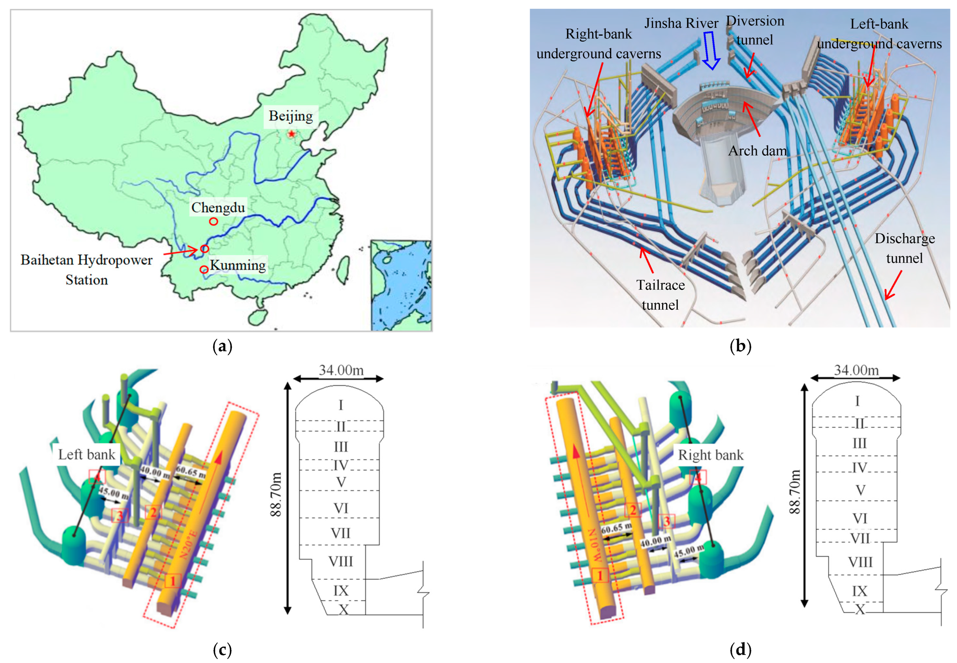
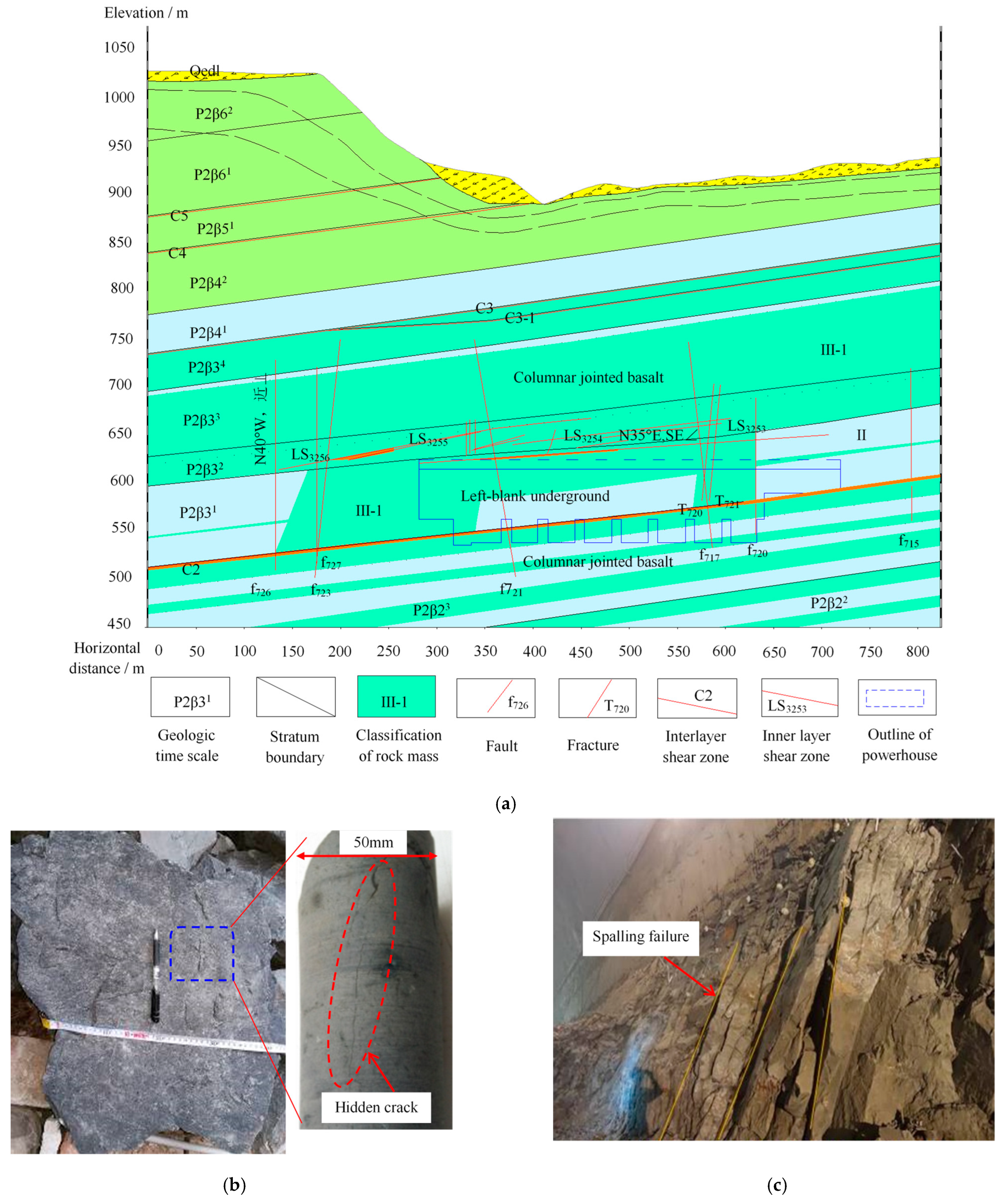
2.1. Engineering Background

The Baihetan Hydropower Station, which is a major national project of “West–East Power Transmission” in China, is located in the lower reaches of the Jinsha River between the provinces of Yunnan and Sichuan. It is the second-largest hydropower station in the world, with a total installation capacity of 16,000 MW [39]. The hydraulic buildings mainly include water diversion and power generation systems, a dam, and flood discharge and energy dissipation systems; the height of the concrete double-curvature arch dam is 289 m. The water diversion and power generation systems on the right and left banks are respectively located in the mountains on both sides of the arch dam upstream, which are composed of four caverns arranged in parallel from upstream to downstream, i.e., the main powerhouse, main transformer cavern, tailrace overhaul gate chamber, and tailrace surge chamber. The excavation size of the underground cavern on the right and left banks is the same, where the main powerhouse is 438 m long, 31–34 m wide, and 88.7 m high; the rock wall thickness between the main transformer cavern, with a height of 39.5 m, a length of 368 m, and a width of 21 m, and the main powerhouse is 60.65 m; and the rock wall thickness between the cylindrical tailrace surge chamber, with a height of 77–93 m and a diameter of 43–48 m, and the main transformer cavern is approximately 85 m. Thus, the entire underground cavern group constitutes the largest underground project in the world, as shown in Figure 1.
Geologically, the Baihetan Hydropower Station belongs to a “V-shaped” landform in a deep-cut valley area and is located in the Emeishan basalt stratum, with the main lithologies being cryptocrystalline basalt, amygdaloidal basalt, and oblique basalt in P2β2–P2β6 layers. Basalt is mostly fresh, dense, and hard, with good integrity, belonging to a complete or massive structure, and it is mainly dominated by class III surrounding rock mass. Due to geological tectonics and special diagenesis, the structural characteristics of the massive basalt (different from columnar-jointed basalt) are complex. In addition to the series of geological structures exposed in the basalt rock mass at the engineering scale, including randomly developed hard structural planes with a medium size (i.e., meters to ten meters), such as joints and cracks, and locally developed weak structural planes with a large size (i.e., more than 10 m), such as long fissures, faults, and dislocation zones, there are a large number of small non-interpenetrating hidden cracks (i.e., centimeters to decimeters) in the basalt blocks, belonging to Class-V hard structural planes [40]. Among the different lithologies, cryptocrystalline basalt is the most prominent. That is, the basalt in this region has significant multiscale structural characteristics, as shown in Figure 2.
The underground caverns of the Baihetan Hydropower Station are under medium-deep buried conditions, with the in situ stress being dominated by the valley tectonic stress, i.e., the horizontal stress is greater than the vertical stress, the first and second principal stresses are horizontal, and the third principal stress is roughly vertical. For the left-bank underground powerhouse, with a vertical buried depth of 260–330 m and an axis direction of N 20° E, the maximum principal stress is in the range of 19–23 MPa, the orientation is N 30–50° W, the dip angle is in the range of 5–13°, and it intersects with the underground powerhouse axis direction at a large angle (i.e., 50–70°). The intermediate principal stress and third principal stress values are in the ranges of 13–16 MPa and 8–12 MPa, respectively. For the right-bank underground powerhouse, with a vertical buried depth range of 420–540 m and an axis direction of N 10° W, the maximum principal stress is in the range of 22–26 MPa, the orientation is N 0–20° E, the dip angle is in the range of 2–11°, and it intersects with the axial direction of the underground powerhouse at a small angle (i.e., 10–30°). The intermediate principal stress and third principal stress values are in the ranges of 13–16 MPa and 8–12 MPa, respectively. Generally, underground caverns are located in medium-high ground-stress areas.
Existing laboratory test results have shown that the uniaxial compressive strength (UCS) of small-sized basalt exceeds 200 MPa; this corresponds to a strength-to-stress ratio greater than 7, indicating that it is difficult for basalt to be damaged under the current conditions [31]. However, due to the complex geological conditions, medium-high ground stresses, and large engineering scales, the fracture problem of the large surrounding rock mass during the excavation of the underground cavern is significant. Many diversified response characteristics and failure modes, such as flaking, slabbing, spalling, spray layer falling, and fracture relaxation, have been widely exposed, and even slight-to-moderate rock bursts have occurred in local areas, bringing difficulties to the cause analysis, safety control, and disaster identification. This highlights the contradictory relationship between the low rock mass strength in engineering practice and the extremely high rock strength in laboratory tests, which is closely related to the presence of ubiquitous hidden cracks. Its essence is the multiscale fracture problem of hard brittle rocks.
Hence, how to scientifically understand the structural characteristics and mechanical properties of this type of rock and how to comprehensively analyze the internal mechanism of disaster phenomena encountered in engineering activities are extremely important questions, and these are also the technical bottlenecks in the prediction and prevention of this type of disaster.

2.2. Structural Characteristics of Basalt Blocks

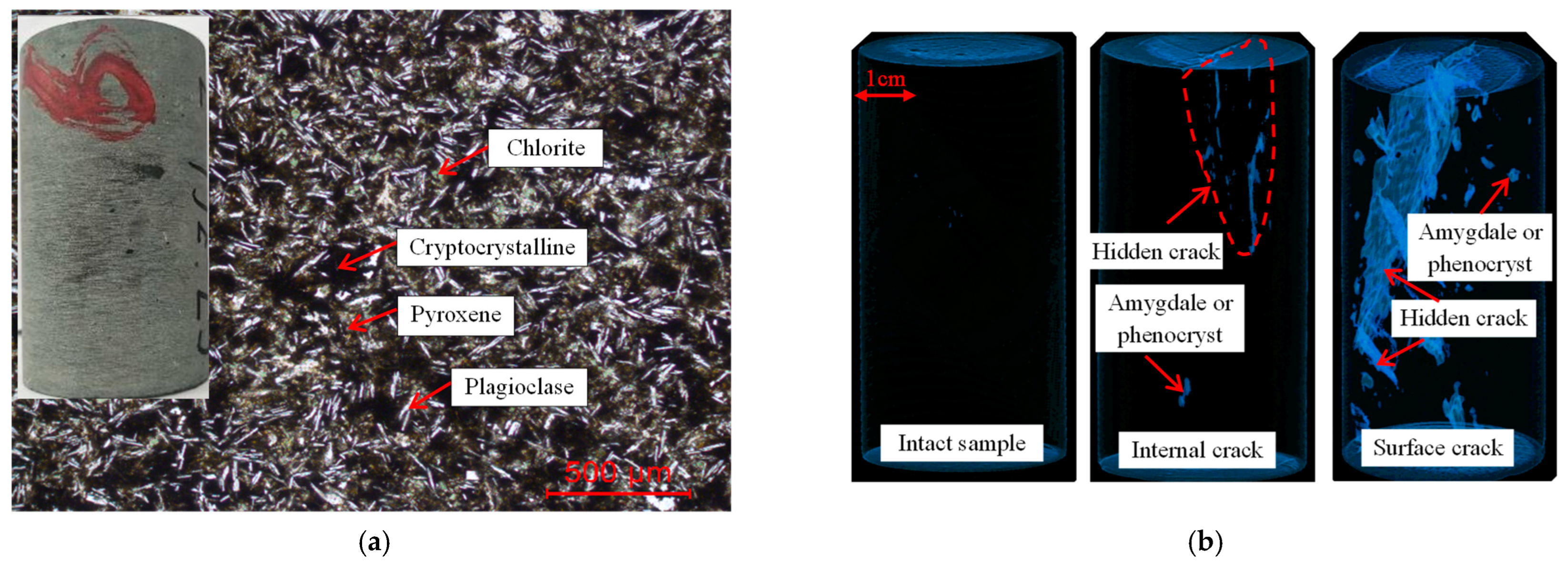
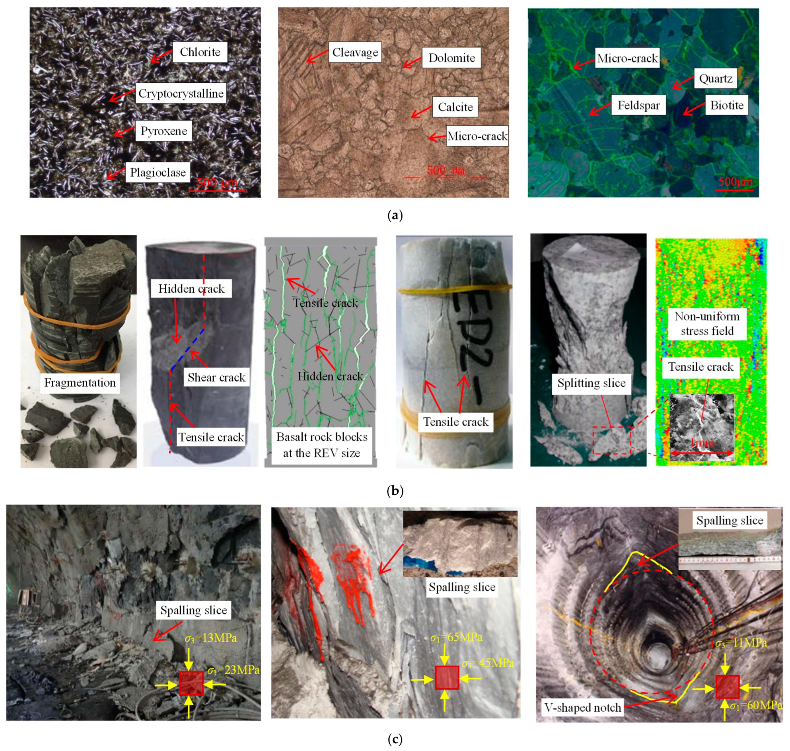
2.2.1. Meso-Structural Characteristics of Basalt

Figure 3a shows the polarizing microscopy image of a thin section of cryptocrystalline basalt magnified 100 times. Small amounts of amygdales or phenocrysts with a small size are scattered, accounting for approximately 2–5% of the tested sample area, where the amygdales are round or oval, with a size range of 0.3–1.5 mm, mainly filled with chlorite; the phenocrysts are in the form of self-shaped plates or columnar, with a size range of 0.25–2 mm, mainly filled with labradorite. The matrix has an intergranular-intercryptic structure, accounting for approximately 95–98% of the tested sample area. Its mineral components are mainly cryptocrystalline, pyroxene, labradorite, and a small amount of chlorite, in which the labradorite is in the form of self-shaped strips, with a major axis diameter range of 0.03–0.25 mm, and pyroxene is finely granular, with a particle size range of 0.01–0.04 mm. Cryptocrystalline is an uncrystallized substance generated during lava eruption; it is dark, blurry, and difficult to distinguish under a microscope.
Figure 3b shows the CT scanning images of some standard cylindrical basalt core samples (i.e., 100 mm in height and 50 mm in diameter). Primary defect structures, such as various fillings and hidden cracks, generally develop inside basalt, with strong randomness, large differences, and no evident rules, indicating a significant heterogeneity overall. Most of the basalt core samples contain hidden cracks with an uneven plane inside or on the sample surface, with a length range of 5–10 cm, accompanied by many secondary randomly distributed microdefects, with a 1–2 cm length, which may be amygdales or phenocrysts. A few samples have good integrity, without any evident surface or internal defects, showing good homogeneity. The density of cryptocrystalline basalt is in the range of 2700–3000 kg/m3, averaging at approximately 2900 kg/m3, and the longitudinal wave velocity is in the range of 3000–5000 m/s, averaging at approximately 4200 m/s, indicating significant variations in the wave velocity and density. Therefore, hidden cracks significantly affect the physical properties of basalt and thus have a crucial impact on its mechanical behaviors.

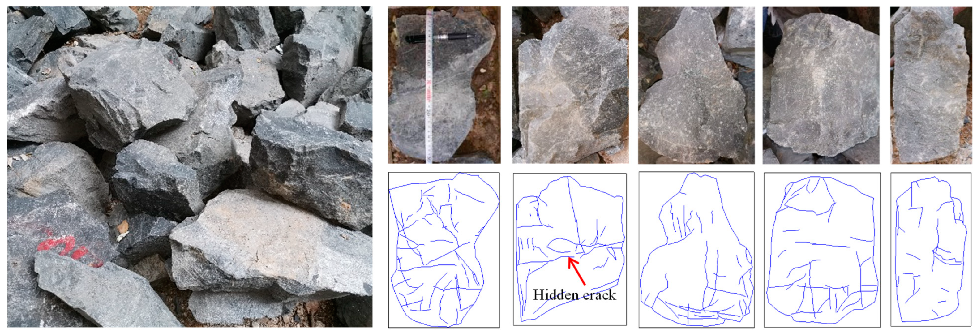
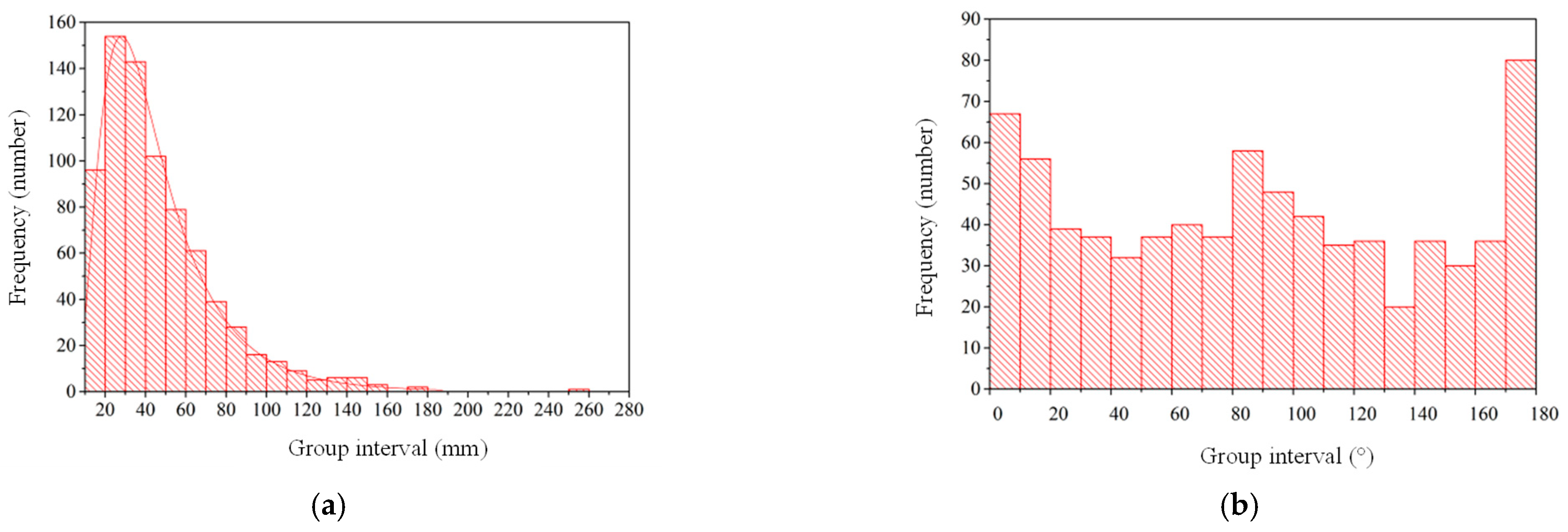
2.2.2. Statistical Characteristics of Hidden Cracks in Basalt

The CT scanning test conducted on the standard-sized basalt core samples provides valuable insights into the distribution characteristics of hidden joints in basalt to a certain extent. However, due to the high CT scanning cost, scanning a large number of basalt samples with a standard size is unrealistic, resulting in limited CT scanning data. Moreover, due to the limited penetration ability of CT scanning and the compactness of basalt itself, CT scanning can only be performed on standard-sized basalt samples, whereas large basalt blocks with a size in the tens of centimeter range are unsuitable, leading to a lack of real and comprehensive data. Therefore, it is difficult to accurately obtain the distribution characteristics of hidden cracks inside basalt by solely relying on the CT scanning results of a limited number of small samples. The following statistical analysis of the superficial hidden cracks in several large basalt blocks is more meaningful.
A series of operations, such as digital photography, image processing, and statistical analysis, was performed on a large number of basalt blocks, generally tens of centimeters in size, taken from underground caverns. The distribution characteristics of the geometric parameters of the hidden cracks were obtained, mainly including the crack length, crack density, and crack orientation (which is defined as the angle between the rock block length direction and the crack direction). In this work, 28 basalt blocks containing approximately 800 hidden cracks with lengths greater than 10 mm were selected and analyzed, as shown in Figure 4 and Figure 5. Irregular hidden cracks are generally developed in basalt blocks, with a hidden distribution, short closure, intermittent extension, and low connectivity. The crack size ranges from a few centimeters to tens of centimeters, and the crack orientation has no evident regularities, which may be closely related to its formation mechanism. The crack orientation conforms to a uniform distribution, and the crack length conforms to a logarithmic normal distribution with σ = 0.58 and μ = 3.68, in which σ represents the standard deviation and μ refers to the average value. Moreover, the areal density P21 is 0.014 mm/mm2, and the areal density P20 is 0.0003 pieces/mm2, where the areal density P21 is the total crack length per unit sample area, and the areal density P20 is defined as the total crack number per unit area of the sample. Hidden cracks are primary tensile fracture structures formed by the rapid condensation and contraction of magma during the diagenesis of basalt. They belong to the Class-V hard structural plane, mainly affecting the mechanical properties of the rock block and, in turn, having a certain influence on the stability of the surrounding rock mass.

3. Creation of a Numerical Model of Basalt

3.1. Fundamental Introduction of FDEM

The modeling domain of the FDEM code Irazu is divided into three-node triangular elements, where four-node crack elements are embedded between all adjacent element boundaries [41], as shown in Figure 6. The mechanical analysis of triangular finite elements adopts the theory of linear elastic continuum. The contact force is generated between all triangular element pairs, where the tangential friction force is calculated according to the Coulomb friction law, and the normal repulsive force is determined using the distributed contact force penalty function method. Adopting the Mohr–Coulomb and maximum tensile stress failure criteria, the cohesive crack elements used to simulate the progressive failure in the material may experience yielding and fracturing in mode I (tensile failure), mode II (shear failure), or mixed mode I–II (tensile–shear failure) based on the local stresses and relative displacements.
The different defects in rocks can be embedded into an FDEM model, represented by pre-existing fractures distributed along the bedding planes. This method can be extended to a general case containing arbitrary structural planes (i.e., the DFN model), which is called the DFN–FDEM model; that is, the DFN model representing defect structures is combined with the FDEM model representing the rock matrix. A DFN model includes two sets of properties: (1) DFN geometric parameters, such as the length, spacing, orientation, and density of cracks. (2) DFN mechanical properties, composed of crack elements that are different from the mechanical properties of the rock matrix. Based on the bonding force of the discontinuities, crack elements can be divided into two types: cohesive type and fractured type. The mechanical behavior of cohesive crack elements is the same as that of the above four-node cohesive crack element model; however, for the crack element of fractured type, the removal of crack elements produces a pure friction discontinuity surface, of which the mechanical behavior is only controlled by the contact model.

3.2. Generation of an SRM Model of Basalt Blocks

To investigate the effects of sample size on the mechanical properties of basalt blocks with hidden cracks, first, a sufficiently large DFN model (i.e., 5000 mm × 5000 mm) was generated using the Monte Carlo method based on the statistical distribution characteristics of the geometric parameters of hidden cracks obtained above. Subsequently, a series of random samplings of different positions and sizes was performed, generating many DFN sub-models of small sizes. Taking uniaxial compression simulation as an example, the widths were 25, 50, 100, 150, 200, 300, 400, 500, and 600 mm, with an aspect ratio of 2, as shown in Figure 7a. The above-generated DFN sub-models representing hidden cracks were embedded into the FDEM code Irazu representing the intact matrix to establish multiple SRM models of different sizes that characterize the real structural characteristics of basalt, i.e., a hybrid DFN–FDEM model, as shown in Figure 7b. Finally, these SRM models were subjected to a series of numerical tests, such as Brazilian basic splitting, uniaxial compression, and triaxial compression, using the calibrated meso-parameters, as shown in Table 1, based on which the size effects of the mechanical behaviors of basalt with hidden cracks, such as the mechanical parameters, stress–strain curves, strength failure criterion, and failure modes, were analyzed. To eliminate and circumvent this potential variability, uncertainty, and randomness, and considering the calculation time constraints, 10 SRM models were created under each size level in this study, and the average value of the sample calculation results was adopted under this working condition.
The meso-parameters used in the FDEM models are classified as elastic parameters of triangular elements (Poisson’s ratio ν, elastic modulus E, and bulk density ρ), strength parameters of crack elements (fracture energy Gf, internal friction angle φ, cohesion c, and tensile strength ft), and penalty values (Pn, Pt, and Pf). Generally, the fracture energy Gf1 for tensile cracks is determined according to the fracture toughness KIc obtained through three-point bending tests or estimated based on the tensile strength from a direct or indirect tensile test. In addition, the fracture energy Gf2 for shear cracks is approximately set to 10 × Gf1, the penalty values (Pn, Pt, and Pf) are typically set to 10–100 times the elastic modulus, and the other parameters can be determined by referring to the test results [42]. In this study, the basalt is composed of a matrix and hidden cracks, where the matrix parameter values (i.e., intact basalt) can be determined by referring to the test results of cryptocrystalline basalt, and the parameter values of hidden joints, which are difficult to obtain by testing, i.e., a cohesive crack element model, can be determined by rationally reducing the parameter values of the matrix. Finally, the parameters of the upper and lower platens can be obtained from the properties of steel.
The meso-parameter calibration is mainly aimed at a large number of numerical samples subjected to Brazilian disc splitting, uniaxial compression, and triaxial compression, with a standard size obtained from the above random sampling. Taking uniaxial compression as an example, 10 numerical samples were selected, including three intact samples and seven cracked samples, and the crack distribution characteristics, such as the number, size, location, and angle, in each sample were different, as shown in Figure 8. Based on the above-determined initial mesoscopic parameters of the basalt with hidden cracks, FDEM simulations were conducted on the 10 numerical samples, and the corresponding mechanical parameters were obtained and compared with the laboratory test results. An iterative calibration procedure was used in this study, involving running an array of numerical mechanical tests, such as the Brazilian disc splitting, uniaxial compression, and triaxial compression, on standard-sized samples to obtain a set of meso-parameters, based on which the macro-mechanical properties obtained by FDEM modeling can match those obtained from the laboratory test, as shown in Table 1.
Table 2 presents the macro-mechanical parameters of the standard-sized basalt determined by laboratory experiments and FDEM simulations [31,32]. On the one hand, the macro-mechanical properties obtained through FDEM modeling have a good consistency with the laboratory test results overall, indicating that the selected FDEM model and the used meso-parameters are reasonable. On the other hand, the mechanical parameters of small-sized basalt samples show significant discreteness, variability, and randomness both in the laboratory tests and numerical simulations. For example, the UCS varies from tens of MPa to hundreds of MPa, with an average of approximately 200 MPa. Evidently, it is difficult to accurately obtain the mechanical properties of basalt by simply performing indoor tests on standard-sized samples. Therefore, it is necessary to use numerical methods to study the mechanical properties of basalt with hidden cracks. In particular, the size effect analysis of the mechanical properties is more meaningful to obtain the real mechanical properties.

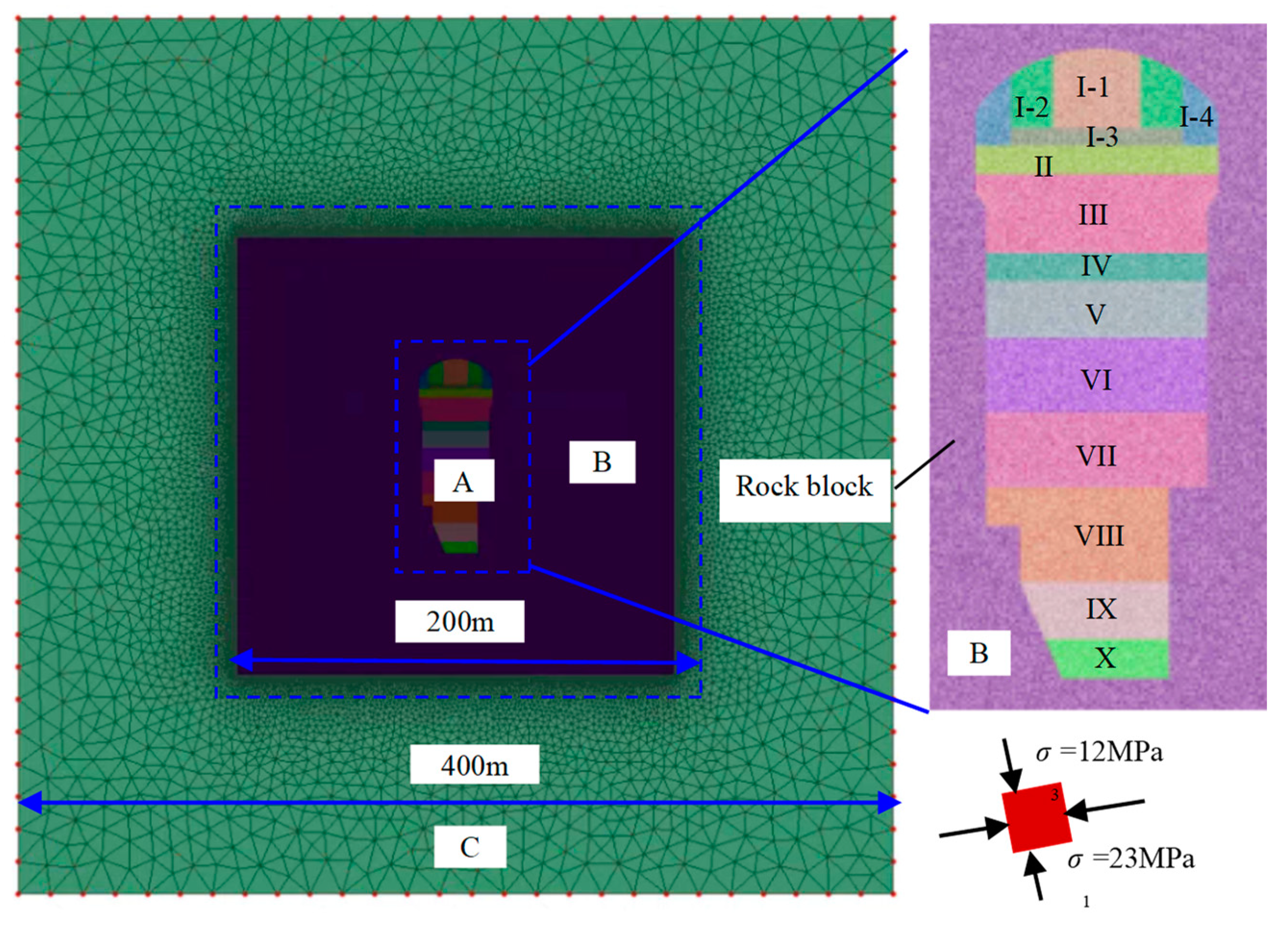
3.3. Establishment of an FDEM Model of Basalt Rock Mass of an Underground Powerhouse

Based on the actual in situ situation of Baihetan Hydropower Station, a 2D FDEM model of a typical section of the left-bank underground powerhouse was established, where only the intact basalt rock mass containing hidden cracks was considered, as shown in Figure 9. This model considers the excavation of an arched tunnel with dimensions of 34 m × 88.70 m, located at the center of a 400 m × 400 m square area, and the size of the model on one side is made 3–5 times the excavation span to minimize the boundary effects. Based on the damage degree and range during rock mass excavation, the model can be classified into three sub-regions with varying degrees of mesh precision. The excavation area (i.e., Region A) was located in the innermost region, whose element size is in the range of 0.5–2 m. The excavation-affected area or interest area (i.e., Region B) with dimensions of 200 m × 200 m that was expected to be fractured was set around the excavation area, with an element size of 0.5 m, and this size was equal to the REV size of the basalt block with hidden cracks. For the non-excavation-affected area or general consideration area (i.e., Region C), where fracture was not expected to occur, the element size was set to a range of 0.5–5 m. Thus, a balance between the computational cost and element suitability required in the numerical simulation to capture the fracture process of the basalt rock mass of underground caverns could be achieved.
Based on the actual in situ stress conditions measured at the engineering site, the primary stress field applied to the numerical model was σ1 = −23 MPa, σ3 = −12 MPa, in which the negative sign indicated that the ground stress was a compressive stress, and a plane strain condition was adopted. A zero-displacement state was used around the outer boundary of the numerical model to simulate the far-field conditions; that is, the horizontal and vertical directions were fixed. During the excavation of the underground caverns, a tunnel face replacement method was used to simulate the 3D effect of tunnel face advancement; that is, the gradual unconstraint of the rock mass due to the tunnel face advancement was captured by gradually reducing the Young’s modulus of the core material from the initial value to zero in the tunnel excavation area, thereby completing the removal of materials in the excavation area. In this model, all the regions containing only hidden cracks were implicitly characterized by the equivalent mechanical parameters of the REV-sized basalt blocks, and a series of checks were performed to ensure that the numerical simulation could accurately reproduce the mechanical response characteristics at the engineering site during the excavation of the underground rock mass, including the deformation, failure characteristics, and extent of the damage area. Table 1 presents the corresponding FDEM model parameters. The total number of simulation time steps was 3 million; each time step was 1.5 × 10⁻⁶ s, and the output frequency of the numerical results was 10000 steps, regardless of the gravitational acceleration.

4. Analysis of Results

4.1. Size Effect of the Mechanical Properties of Basalt Blocks

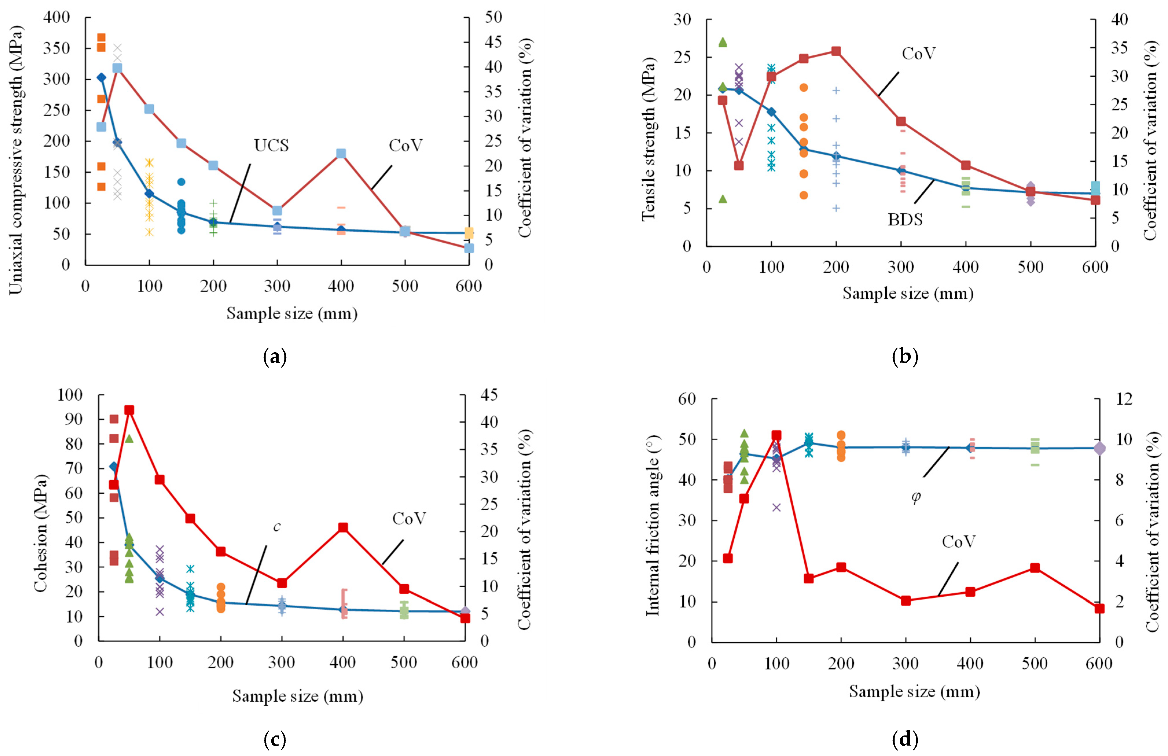
4.1.1. Size Effects of Mechanical Parameters

To grasp the size effects of the mechanical parameters of basalt blocks with hidden cracks, the mechanical parameters and the coefficients of variation (CoV) of multiple SRM models of various sizes were calculated. Based on the variation trends in each mechanical parameter with increasing sample size, the mechanical REV and corresponding equivalent mechanical parameters were determined, as shown in Figure 10, where the scatter points represent the discrete data of the mechanical parameters of different samples with the same size; the blue broken-line points denote the average value, and the red broken-line points represent the CoV, which is defined as the ratio of the standard deviation to the average value. In this study, an acceptable CoV was less than 10%.
As shown in Figure 10a, the UCS average value of basalt blocks with hidden cracks decreases gradually with the increase in the sample size, with a more evident decreasing trend for small sizes, and it remains roughly constant after exceeding a certain size. With the increase in the sample size, the UCS fluctuation range and dispersion degree of different samples with the same size decrease, and the CoV exhibits a trend that first fluctuates and then nonlinearly decreases; in particular, this decreasing trend is more evident at small sizes. Specifically, when the sample size is less than 200 mm, the variation range of the UCS values of the various samples with the same size is wide, and the decrease trend in the CoV is the most evident, with a value greater than 20%, meaning that the model under this size cannot represent the structural characteristics of basalt. For a sample size range of 300–400 mm, the CoV is in the range of 10–20%, where the CoV of the samples with a size of 400 mm is slightly greater than 20%, and the UCS fluctuation range is significantly reduced at this time. The CoV is below 10% when the sample size is ≥500 mm, and the UCS tends to an asymptotic value, indicating that the model at this size can represent the entire rock block. Therefore, the basalt REV size characterized on the basis of the UCS fluctuation range and dispersion degree of the samples of various sizes is 500 mm, at which the UCS is 52.53 MPa, which is approximately 20% of that of a standard-sized basalt sample (i.e., 100 mm in height and 50 mm in diameter).
Similarly, the entire variation trends in the tensile strength (BDS) and cohesive strength c are the same as those of the UCS, as shown in Figure 10b,c. Therefore, the REV size determined based on the property variation degree is 500 mm, at which BDS = 7.14 MPa and c = 12.50 MPa, which are approximately 30% of the corresponding mechanical parameters of the standard-sized basalt sample. In addition, the overall change trend in the internal friction angle φ is not evident, and the CoV of the basalt samples under each size is less than 10%. When the sample size ≥ 150 mm, φ tends to stabilize, with a value of approximately 47.5°, which is slightly higher than the corresponding mechanical parameter of basalt samples with a standard size, as shown in Figure 10d.
In summary, the mechanical REV size of the basalt block containing hidden cracks determined based on the variation trends in the mechanical parameters of the samples with different sizes is 500 mm, at which UCS = 52.53 MPa, BDS = 7.14 MPa, c = 12.50 MPa, φ = 47.5°, and E = 30.00 GPa. Therefore, these equivalent mechanical parameters can be considered the equivalent continuum properties and can be used as input parameters for intact rock mass or rock blocks in jointed rock mass at the engineering scale based on a continuum approach. On the one hand, the mechanical parameters of basalt with a standard size obtained by laboratory tests are inaccurate and significantly different from those of larger-sized basalt blocks, which cannot be directly applied to engineering sites, indicating that it is necessary to perform in situ tests on larger-sized samples. On the other hand, the REV size of the basalt blocks obtained from the numerical simulation analysis is approximately in the range of 300–500 mm, corresponding to the sample size used in the in situ tests. However, the in situ tests cannot be implemented in large numbers in many engineering projects due to various limitations. Therefore, it is necessary to perform a corresponding size effect analysis on the basis of establishing a numerical model that characterizes the real structural characteristics of rock blocks, based on which the obtained research results will be more meaningful and valuable.

4.1.2. Size Effects of Stress–Strain Curve Characteristics

Figure 11 shows the deviatoric stress–strain curves of different-sized basalt samples with hidden cracks under triaxial and uniaxial compression, obtained from FDEM simulations and laboratory tests. As shown in Figure 11a, the pre-peak nonlinear characteristics of the stress–strain curves of intact basalt under uniaxial compression are not evident, and the slope of the stress–strain curve is high, indicating linear elasticity. The post-peak stress drops rapidly, and some samples do not clearly exhibit a post-peak curve, indicative of extremely strong brittleness characteristics. With the increase in the confining pressure, the stress–strain curves of the intact sample still exhibit linear elasticity before the peak and a rapid stress drop after the peak, unlike the brittle-to-ductile transition characteristics of other hard brittle rocks, such as marble and sandstone, under high confining pressures [43]. In other words, although the residual strength of basalt increases significantly with increasing confining pressure, its brittleness is not remarkably influenced by the confining pressure, without evident plasticity and yield platform near the peak under high confining pressures (e.g., σ3 ≥ 50 MPa). Therefore, intact basalt shows significant elastic–brittle mechanical properties, with evident brittle characteristics, and the FDEM results are consistent with the laboratory test results.
As shown in Figure 11b,c, the stress–strain curves of basalt with local hidden cracks or many hidden cracks under uniaxial compression are serrated before the peak; that is, there are many evident phenomena in that the stress first enhances and later reduces, and the slope of the stress–strain curve is lower than that of the intact samples, showing significant nonlinear characteristics. The post-peak stress drops gradually, with the decrease in the brittleness degree. With increasing confining pressure, the stress–strain curves of basalt samples still exhibit a pre-peak jagged shape, the post-peak stress drops more gradually, and even an evident yield platform occurs at the post-peak or near the peak stage, with a significant increase in plasticity. Therefore, basalt with local or many hidden cracks exhibits elastoplastic mechanical characteristics, with significantly reduced brittleness and significantly enhanced plasticity.
As shown in Figure 11d, the pre-peak stress–strain curve of basalt containing sufficient hidden cracks at the REV size under uniaxial compression is relatively smooth, and the slope of the stress–strain curves is significantly reduced compared with that of intact basalt, indicative of nonlinear and elastoplastic mechanical characteristics. There is an evident yield plateau near the peak, and the post-peak stress decreases more gradually. With increasing confining pressure, the pre-peak nonlinear characteristics of basalt blocks are more significant, and the yield platform range near the peak increases; in particular, there is an evident strain-hardening phenomenon under medium and high confining pressures (i.e., σ3 ≥ 20 MPa), showing a remarkable ductility characteristic. Therefore, the basalt block containing sufficient hidden cracks at the REV size exhibits elastic–ductile mechanical characteristics, with a prominent increase in the plasticity and ductility and a noticeable decrease in the brittleness.
In summary, the stress–strain curve characteristics of basalt vary with the increase in the sample size, from the elastic–brittle mechanical properties of small-sized samples to the elasto–plastic properties of medium-sized samples with local defects and then to the ductile mechanical properties of the REV-sized samples with sufficient defects, with a continuous decrease in the brittleness degree. The mechanical characteristics of rocks are the comprehensive effects of the structural characteristics under mechanical action, in which both defect structures (i.e., sample size) and confining pressure play a key role. For small-sized basalt samples with strong homogeneity, their mechanical properties are mainly influenced by the confining pressure, exhibiting significant brittleness even under elevated confining pressures. Conversely, for large-sized basalt blocks characterized by pronounced heterogeneity, their mechanical properties are jointly influenced by both the internal structure and confining pressure, resulting in a substantial reduction in brittleness.

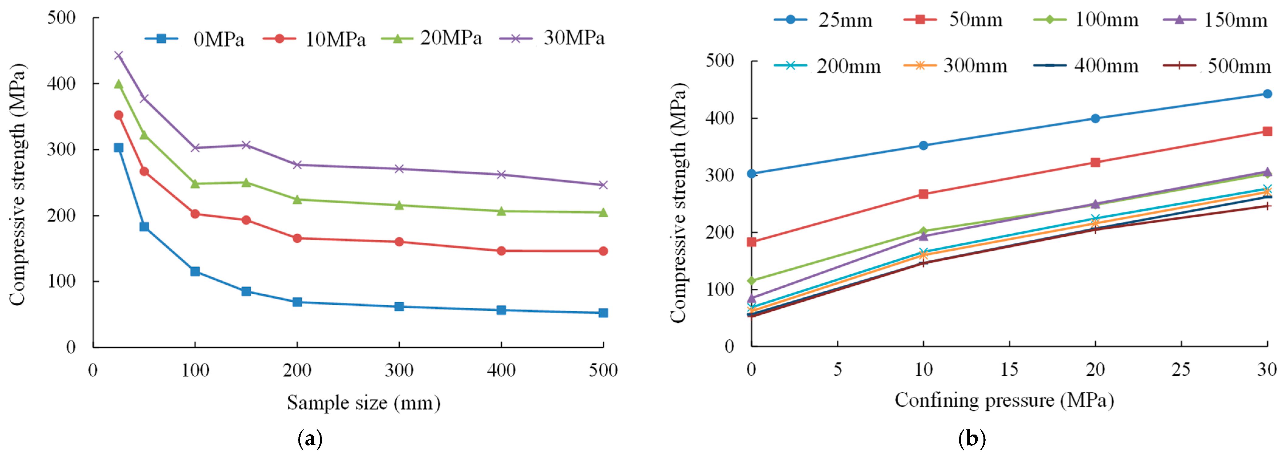
4.1.3. Size Effects of Strength Criterion

Figure 12 shows the strength variation curves of basalt samples with different sizes containing hidden cracks under uniaxial and triaxial compression. Figure 12a shows the relationship between the compressive strength of the basalt and the sample size under various confining pressures. The UCS of basalt decreases from 303.06 MPa to 52.53 MPa as the sample size increases from 25 mm to 500 mm, reflecting a reduction rate of approximately 82.67% and indicating a significant strength reduction trend. The obtained REV size is relatively large, approximately 500 mm, highlighting a notable size effect. However, with an increase in the confining pressure to 30 MPa, the compressive strength of basalt decreases from 442.75 MPa to 246.33 MPa as the sample size increases from 25 mm to 500 mm, resulting in a reduction rate of approximately 44.36%. Hence, the strength reduction trend weakens, and the obtained REV size is smaller, approximately 150 mm, indicating a less significant size effect. Thus, the rise in the confining pressure mitigates the strength size effect of basalt to a certain extent.
Figure 12b shows the relationship between the compressive strength of basalt and confining pressure under different sample sizes. The compressive strength of intact basalt with smaller sizes increases from 303.06 MPa to 442.75 MPa as the confining pressure increases from 0 MPa to 30 MPa, demonstrating an approximately linear increasing trend. This behavior aligns with the linear strength criterion, such as the MC strength criterion. However, the compressive strength of basalt blocks with larger size (i.e., 500 mm) increases from 52.53 MPa to 246.33 MPa as the confining pressure increases from 0 MPa to 30 MPa; therefore, the linear increasing trend is weakened, which approximates to a nonlinear strength criterion such as the Hoek–Brown (HB) strength criterion. Consequently, as the sample size increases, the strength criterion of basalt transitions from linear to nonlinear [44].
Based on the obtained variation trend in the UCS of basalt containing hidden cracks with the increase in the sample size, a prediction model for basalt strength considering the size effect is proposed, as expressed in Equation (1). Moreover, this strength size effect model is integrated into the classical HB strength failure criterion for intact rocks, as expressed in Equation (2). This integration results in the establishment of a strength failure criterion for basalt containing hidden cracks that accounts for the size effect, as expressed in Equation (3). In these equations, UCSd and UCSd50 represent the UCS of rock samples of arbitrary diameters and a diameter of 50 mm, respectively, and d represents the sample size. σ1 and σ3 denote the maximum and minimum (confining pressure) principal stresses, respectively; σci represents the uniaxial compressive strength of the intact rock; and m is the rock material constant. It is worth noting that this study serves as a preliminary exploration and attempt on the rock strength criterion considering the size effect, due to the necessary simplification of the numerical model. Therefore, further systematic exploration in this area will be conducted using various methods.
UCS d = UCS d 50 ( d 50 ) 0 . 36
σ 1 = σ 3 + σ ci ( m σ 3 σ ci + 1 ) 0.5
σ 1 = σ 3 + UCS d 50 ( d 50 ) 0 . 36 ( m σ 3 UCS d 50 ( d 50 ) 0 . 36 + 1 ) 0.5
In summary, as the confining pressure increases, the size effect on the strength of basalt is somewhat mitigated. Moreover, as the sample size increases, the failure criterion for basalt strength shifts from linear to nonlinear. On the one hand, at lower confining pressures, samples contain numerous micro-defects, leading to significant heterogeneity and strength size effects. Conversely, under high confining pressures, the micro-defects within the samples are compressed and closed, resulting in a decrease in the heterogeneity and a significant weakening of the strength size effect. On the other hand, basalt samples with smaller sizes have fewer defects and higher homogeneity and are evidently affected by the confining pressure, showing an approximately linear increase in the peak strength with increasing confining pressures. However, larger samples have more defects and greater heterogeneity and exhibit mechanical properties influenced by both the defect structure and confining pressure, resulting in a nonlinear increase in the peak strength with increasing confining pressure. Therefore, linear strength criteria are suitable for small-sized rocks with good homogeneity, while nonlinear strength criteria are more applicable to large-sized rock mass or blocks with pronounced heterogeneity.

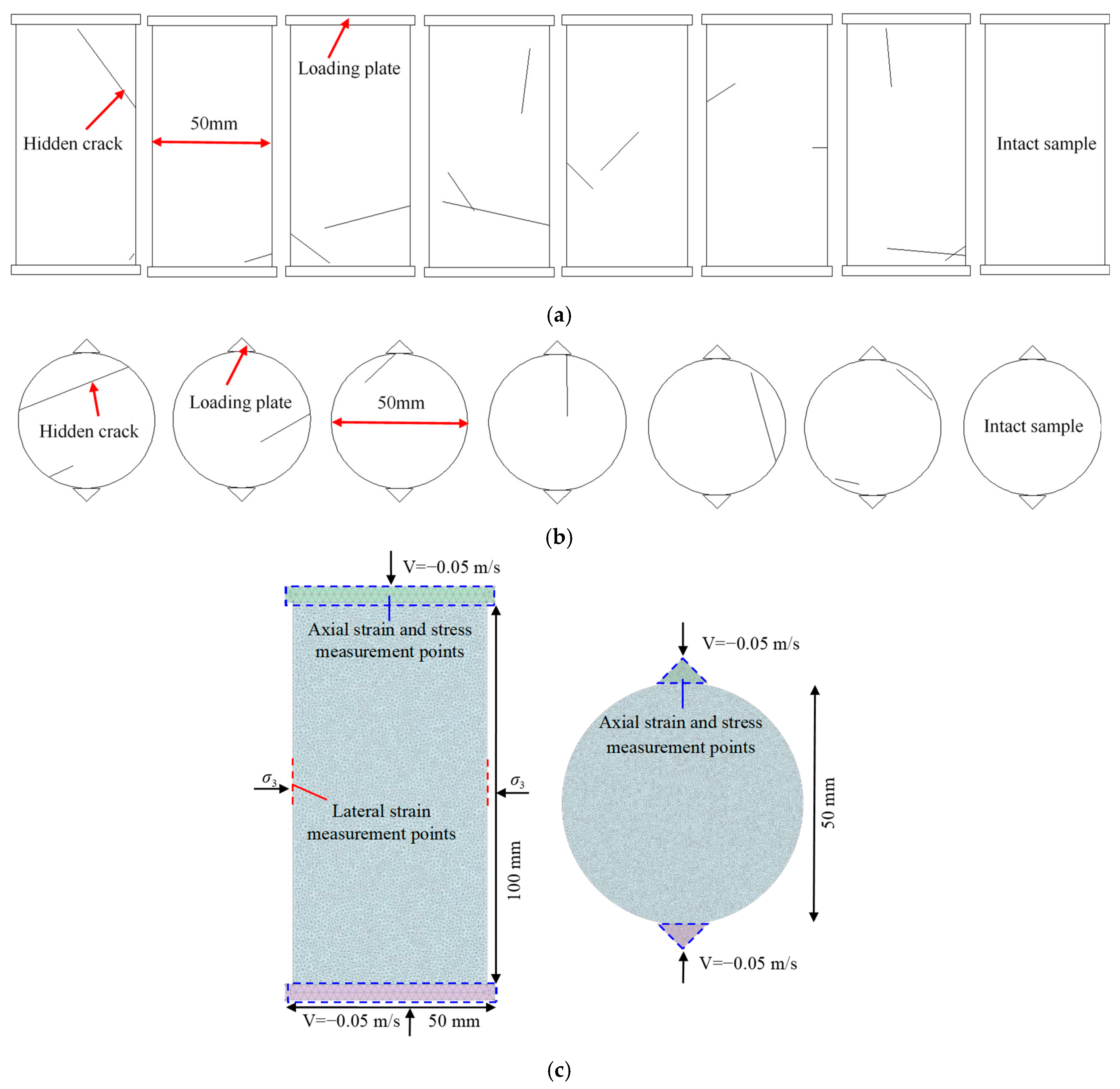
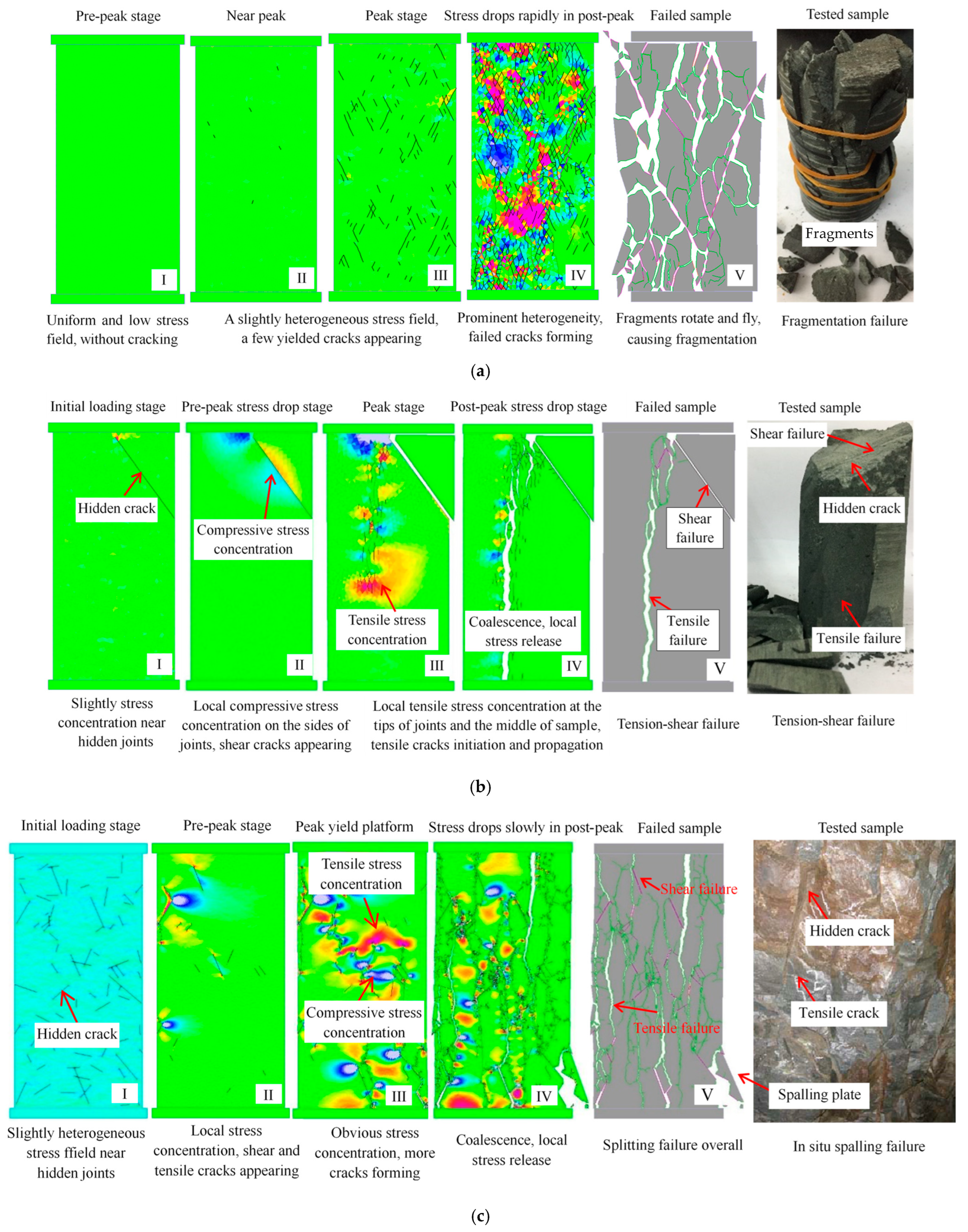
4.1.4. Size Effects of Failure Modes

Figure 13 shows the failure modes of basalt samples of various sizes with hidden cracks under uniaxial compression obtained from FDEM simulations and laboratory tests or field observations, where the black, red, and cyan lines represent yielded cracks, shear failure cracks, and tensile failure cracks, respectively, and the marker points I–V represent different failure stages.
As shown in Figure 13a, for a small-sized basalt sample (i.e., 50 mm × 100 mm) with few hidden cracks, a fragmentation failure mode under uniaxial compression appears, in which the longitudinal and transverse tension cracks are closely interlaced, accompanied by a loud noise and violent ejection, and many fragments appear after failure, indicative of extremely evident brittle characteristics. Basalt has good homogeneity at the grain scale owing to the features of dense arrangement, high strength, and small particle size. Under axial loading, the pre-peak stress field is relatively uniform, and the stress value is small, which is insufficient to reach the local strength of the rock material to form local fractures, without resulting in fractures. When the axial stress approaches the peak strength, the overall stress level is high, and a slight nonuniform stress field occurs. A small number of yielded cracks, which are randomly distributed, appear once the local stress exceeds the local strength of the rock material. The axial stress reduces sharply after the peak, and a prominent heterogeneous stress field, including local stress relief zones and stress concentration zones, is formed, in which more yielded cracks emerge in the stress concentration areas, and the shear and tensile failure cracks in the stress-relief areas initiate instantaneously due to the sliding and opening of crack elements, and they continue to propagate and coalesce to form macro-fractures, accompanied by a large number of fragments. Therefore, the failure process of the entire intact basalt is short, showing a fragmentation failure mode, which is consistent with the experimental results; that is, a tensile failure mechanism caused by high stresses plays a leading role.
As shown in Figure 13b, for the medium-sized basalt sample (i.e., 100 mm × 200 mm) with a small number of local hidden cracks, the failure mode can be tension failure, tension–shear composite failure, or shear failure. Basalt with local hidden cracks is a typical heterogeneous rock material. Due to the difference in the elastic modulus between the matrix and hidden cracks, a slight heterogeneous stress field occurs near the cracks in the initial loading stage, because of which the local strength of the rock material cannot be reached to form local fractures. With the increase in the loading, a significant stress concentration area is formed near the hidden cracks in the pre-peak loading stage; that is, a tensile stress concentration zone appears in the upper and lower tips of the hidden cracks, and a compressive stress concentration zone appears on both sides. Shear failure occurs first on the hidden crack surfaces due to the low shear strength, and then, a tensile crack (i.e., wing crack) approximately parallel to the loading direction appears at the hidden crack tips once the local tensile stress exceeds the tensile strength of the rock material. In the post-peak stage, the microcracks formed continue to expand and penetrate, leading to a macro-failure of the sample. Therefore, the failure process of basalt with local hidden cracks takes more time compared with that of the intact basalt, with a tensile–shear composite failure mode, which is consistent with the experimental results, that is, the initial local cracks play a key role (i.e., structurally controlled failure).
As shown in Figure 13c, the basalt blocks at the REV size (i.e., 500 mm × 1000 mm) with sufficient hidden cracks exhibit a splitting failure mode under uniaxial compression, in which multiple longitudinal tensile cracks penetrate both ends of the samples, shear failure occurs at the hidden cracks, and tension failure occurs in the matrix near the crack tips, which is dominated by tensile failure overall. The heterogeneity of the basalt block with sufficient hidden racks at the REV size is significantly enhanced, resulting in prominent heterogeneous stress fields near the initial defects during the pre-peak loading process, at which some shear and tensile microcracks initiate, expand, and penetrate to form local failure that is approximately parallel to the loading direction. The stress field heterogeneities in the pre-peak and post-peak stages are more significant; more local damages composed of shear and tensile cracks are formed, and they continue to expand, interact, and coalesce along the loading direction, which lead to the final failure of the rock block, accompanied by the longitudinal spalling of multiple thin plates with a thickness in the range of 5–10 cm and tens of centimeters in length. Therefore, basalt blocks containing sufficient hidden cracks exhibit a splitting failure mode, which is consistent with the in situ failure results, i.e., a tensile failure mechanism caused by the combined effect of the stress and structure.
In summary, the failure mode of basalt varies with the sample size, from the fragmentation failure of small-sized intact basalt to the structure-controlled failure of medium-sized basalt with local hidden cracks, and then to the splitting failure of the REV-sized basalt with sufficient hidden cracks. The sample size significantly affects the rock mechanical behaviors, and it is essentially the influence of its own structural characteristics with the change in the sample size; that is, with the increase in the sample size, there is a transition from a small-sized intact sample to a medium-sized sample with local defects, and then to a REV-sized sample with sufficient defects, with the gradual decrease in the homogeneity. The meso-structural characteristics of basalt itself at the grain scale (i.e., a good homogeneity) are key factors causing the significant brittleness, high strength, and fragmentation failure mode in intact basalt. However, the primary hidden cracks (i.e., an evident heterogeneity) remarkably influence the fracture propagation paths and stress field distributions during the loading process, which is a key factor leading to the long duration of the failure process, evident strength reduction, strong randomness in the mechanical parameters, and significant change in the failure mode. In summary, it is significant to consider the structural characteristics of a real rock to understand its mechanical behaviors and fracture mechanism.

4.2. Fracture Behaviors of Basalt Rock Mass during Excavation

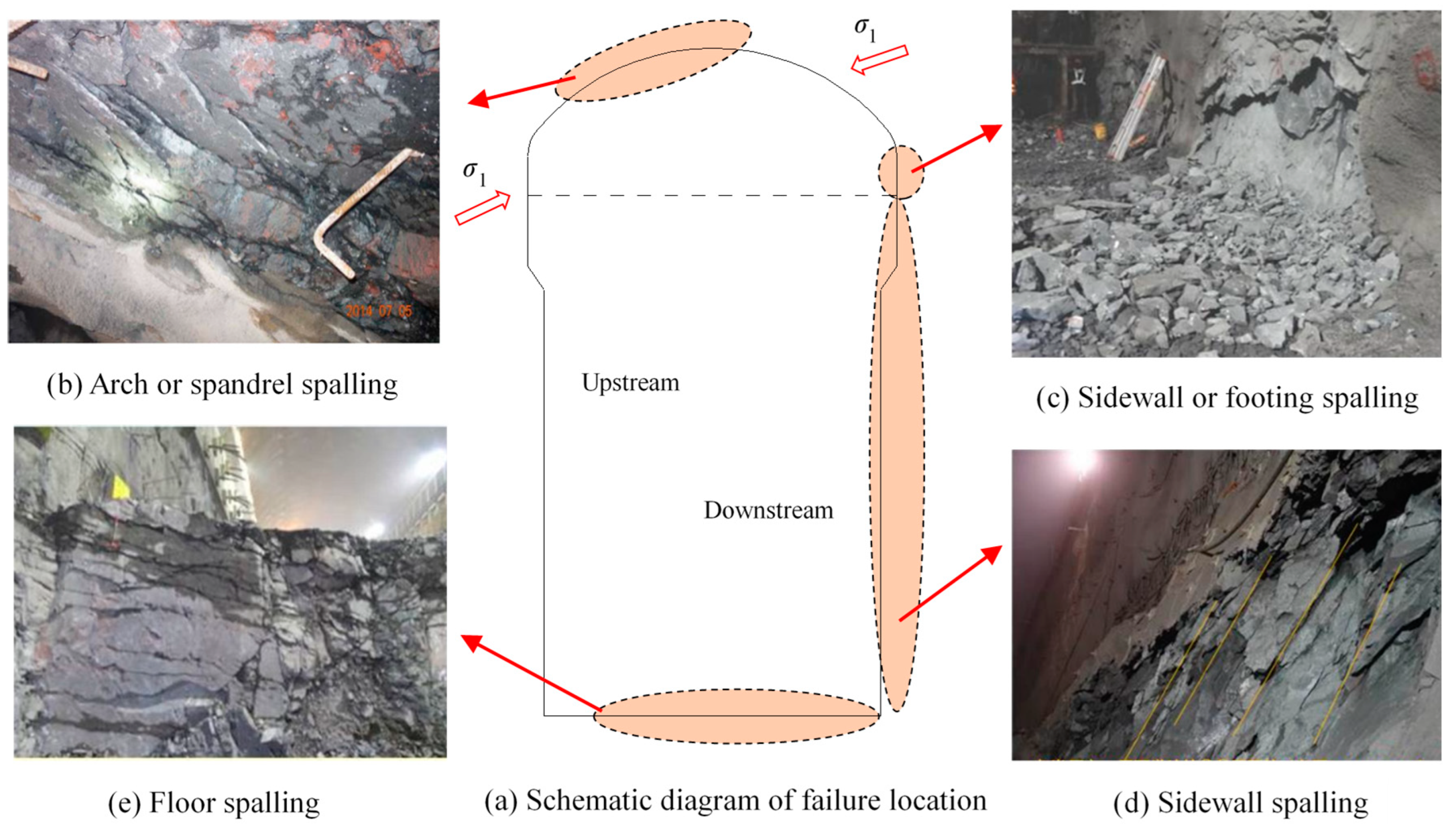
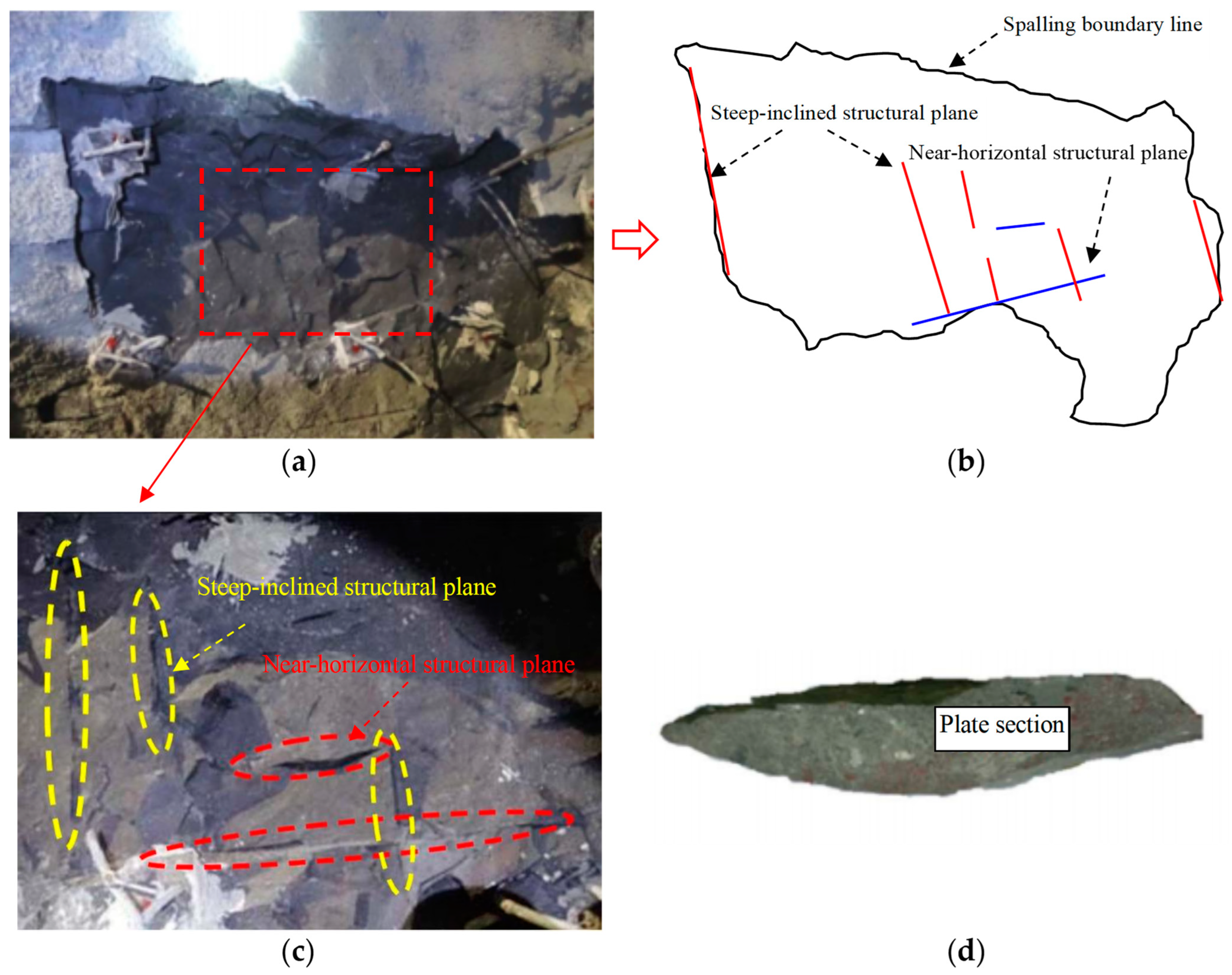
4.2.1. Failure Features of Basalt Rock Mass Found in Underground Caverns

Due to the complex conditions of basalt, such as strong brittleness, high initial geostress, significant multiscale structural features, and huge engineering scale, the fracture problem during the excavation of an underground cavern is prominent, exhibiting various typical hard brittle rock failure modes and response characteristics. Examples include flaking, spalling, spray layer cracking, and block shedding, among which spalling is the most common, bringing significant challenges to the stability control of surrounding rock mass in underground engineering. Generally, based on whether the macro-scale structural planes are exposed near the fracture surfaces of surrounding rock mass, the brittle fracture of an underground powerhouse can be roughly classified into two types: spalling failure of the intact rock mass containing only hidden cracks and spalling failure of the rock mass containing hidden cracks and engineering-scale random joints [45].
Approximately 40% of the spalling failure area is located in the intact surrounding rock mass, without evident engineering-scale structural planes, mainly developing hidden cracks that are discrete, irregular, and short, which have a certain influence on the spalling failure of the surrounding rock mass, as shown in Figure 14. The distribution position of this spalling failure is relatively stable and shows evident regularity, mainly located in the upstream spandrel and arch and downstream footing, floor, and sidewall. The area of the spalling failure zone is generally large, the fracture surface is flat and fresh, parallel to the cavern surface, and the thickness of the spalling rock plate is small, generally in the range of 0–5 cm. Spalling failure belongs to the shallow surface fracture of the surrounding rock mass near an excavation face, corresponding to the highly excavation damage zone (HDZ). In addition, a fracture of a certain depth occurs inside the surrounding rock mass, corresponding to the excavation damage zone (EDZ). The spalling failure depth of the surrounding rock mass of the underground powerhouse is generally in the range of 0–0.5 m, partly in the range of 0.5–1.0 m; the relaxation depth of the top arch surrounding rock mass is generally in the range of 1.0–2.5 m, reaching a range of 2.0–4.0 m in local areas; and the relaxation depth of the side-wall surrounding rock mass is generally in the range of 2.0–5.0 m, with a value range of 6.0–8.0 m locally. This type of spalling failure is a macroscopic stress-controlled failure.
In addition to the spalling failure of the intact basalt rock mass, the rest of the spalling failure occurs in a relatively intact massive rock mass with random joints. The rock mass with this type of spalling failure contains fewer joints, and the number of joints per unit volume is mostly in the range of 0–6, generally not more than two groups of joints. It is a hard and unfilled Class IV structural plane with intermittent extension, insufficient development, low connectivity, and a length of approximately several meters, and the joints typically intersect with the tunnel axis and the tunnel wall at a large angle, as shown in Figure 15. The regularity of the spatial location of this type of spalling failure is not as strong as that observed in the intact rock mass, generally located in the top arch and spandrel upstream and in the sidewall, footing, and floor downstream, and other local areas may also appear. The fracture surface is relatively fresh, rough, and uneven, roughly parallel to the excavation surface; most of the initial joints do not fail along the joint surface and remain on the fracture surface; and a small number of initial joints constitute the boundary of the spalling failure area. The thickness of the spalling rock plate is greater than that of the intact basalt rock mass, generally greater than 5 cm, and it is in the range of 10–50 cm in some areas. Evidently, this non-interpenetrated joint affects the failure mode of the rock mass to a certain extent, and the formed spalling failure is called macroscopic stress–structure-combined failure.

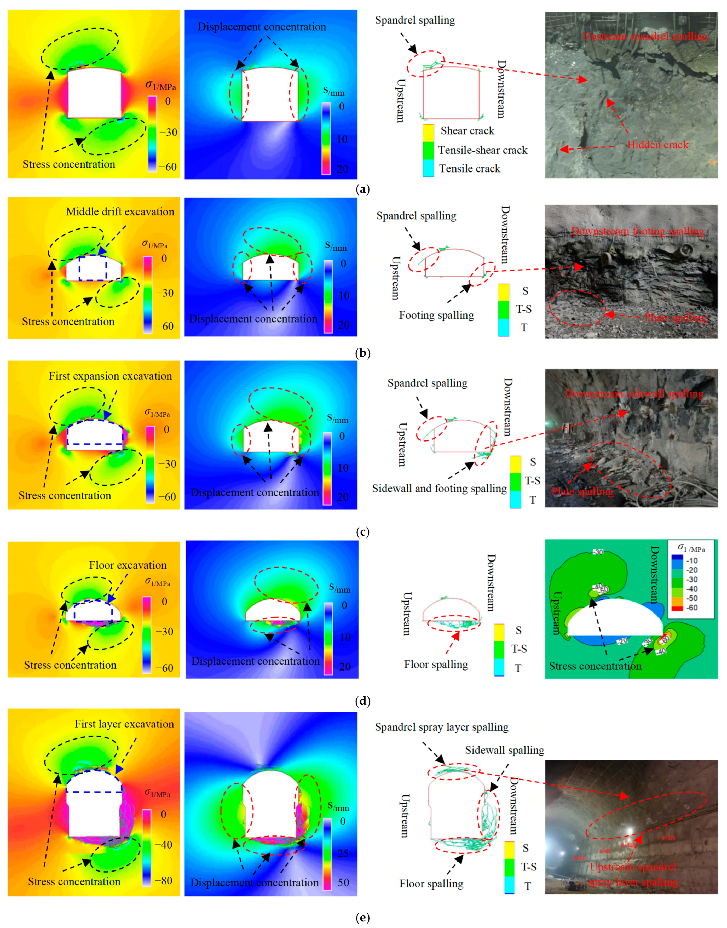
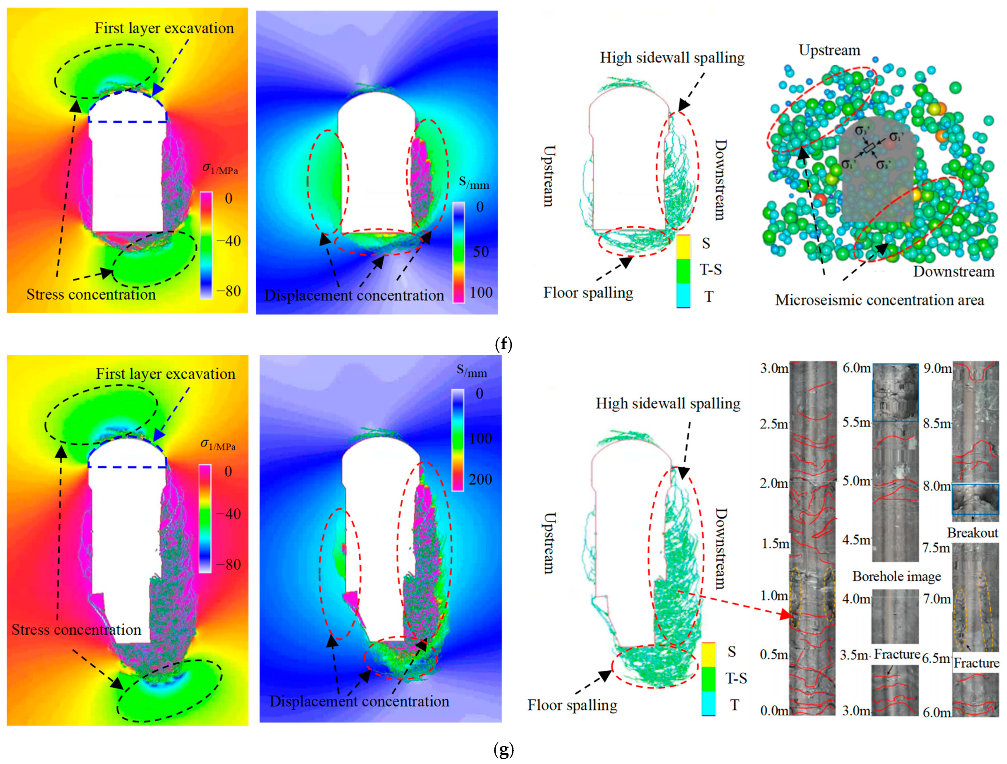
4.2.2. Fracture Evolution Laws of Basalt Rock Mass during Excavation

The left-bank underground powerhouse was excavated in 10 layers due to its large size. For the first layer (I), the scheme of first excavating the middle pilot tunnel and then expanding the excavation on two sides in sequence was adopted. On this basis, each remaining layer (II–X) was excavated step by step. Based on the focus of this paper, in the numerical simulation, only a systematic analysis and elaboration of the intact basalt rock mass was conducted, in which the excavation sequence was the same as the actual situation of the underground powerhouse. After the numerical simulation calculations, the fracture evolution process parameters of the basalt rock mass during the excavation of each layer of the left-bank underground powerhouse, such as the stress fields, deformation fields, and crack propagation, were quantitatively analyzed, as shown in Figure 16, and they were compared with the project site monitoring results or existing results reported in the literature. Thus, the progressive fracture laws of the basalt rock mass in the underground cavern under high ground stresses and strong excavation unloading could be thoroughly revealed [46].
As shown in Figure 16a, during the middle pilot tunnel excavation stage of the first layer, the initial in situ stress balance was broken to form a secondary stress with continuous excavation, mainly including a stress release area and a stress concentration area. The stress concentration area was mainly distributed in the upstream roof and the downstream floor, and some local corners, such as the upstream footing and downstream spandrel, were also in the stress concentration area, with the stress magnitude ranging from 30 to 60 MPa, while the stresses of the sidewalls in the upstream and downstream were significantly reduced. The displacement concentration area was mainly located at the sidewalls of the upstream and downstream and the downstream roof, which was roughly opposite to the distribution characteristics of the stress concentration area, i.e., an approximately vertical relationship, and the overall deformation value was small, generally in the range of 5–10 mm, which was mainly the elastic deformation due to excavation unloading. With the continuous excavation advancement and stress adjustment, cracks started to initiate along the maximum principal stress direction once the stress concentration exceeded the ultimate strength of the basalt rock mass, and continued to expand, penetrate, and coalesce to form local plate or layered spalling failure, with the fracture surface being approximately parallel to the excavation-free surface. Spalling failure was mainly located at four corner areas; in particular, the spalling failure in the upstream spandrel or top arch was significant, corresponding to the distribution features of the stress concentration area. The depth of the excavated damage zone was generally 1.0–2.0 m, mainly exhibiting tensile cracks or tensile–shear composite cracks.
In the first enlarged excavation stage of the first layer and the floor enlarged excavation, as shown in Figure 16b,c, the excavation span and height increased continuously with further excavation of the rock mass on both sides of the middle pilot tunnel and the floor, i.e., the span increased from 12 m to 24 m, and the height increased from 11.2 m to 13.6 m. The overall distribution characteristics of the principal stress were consistent with those in the middle pilot tunnel excavation stage; however, the degree and range of the stress concentration area continued to increase, particularly in areas such as the upstream arch and spandrel and downstream sidewall and footing. The displacement distribution characteristics in this stage were the same as those in the middle pilot tunnel excavation stage, while the range and degree of the displacement concentration area increased significantly, which was roughly opposite to the distribution characteristics of the principal stress concentration area; in particular, the deformation in the downstream sidewall and footing increased significantly. The overall deformation value was small, generally in the range of 10–15 mm, and mainly attributed to the inelastic deformation caused by the brittle fracture of the rock mass. The spalling failure of the rock mass formed by the high stress concentration was mainly located in the spandrel of the upstream and downstream sidewalls and footing of the enlarged excavation area, corresponding to the distribution position of the stress concentration area. The depth of the excavation damage zone was generally in the range of 2.0–3.0 m, exhibiting mainly tensile cracks or tensile–shear cracks.
In the second enlarged excavation stage of the first layer, as shown in Figure 16d, with the further excavation of the rock mass on both sides of the cavern, the excavation span increased continuously from 24 m to 34 m, and the overall distribution characteristics of the stress fields were unchanged. However, the degree and range of the stress concentration areas increased, particularly in the downstream floor. The displacement distribution characteristics remained unchanged in this stage, whereas the range and degree of the displacement concentration areas increased significantly, with the deformation of the downstream floor being the largest, which was roughly opposite to the distribution characteristics of the stress concentration areas. The deformation value was generally in the range of 15–20 mm and mainly attributed to the inelastic deformation caused by the brittle fracture of the rock mass. The spalling failure of the rock mass was mainly located in the downstream floor, and the depth of the excavation damage zone further increased, generally in the range of 2.0–4.0 m, mainly exhibiting tensile cracks or tensile–shear cracks.
In the second-to-fourth layer excavation stage, as shown in Figure 16e, the excavation height increased continuously from 13.6 m to 32.7 m as the underground cavern was further excavated downward, and the overall distribution characteristics of the stress fields were the same as those in the first layer excavation stage, whereas the degree and range of the stress concentration areas gradually increased, resulting in a stress value in the range of 40–80 MPa. The distribution characteristics of the displacement fields were slightly different from those of the first layer excavation stage, and the displacement concentration area was mainly located in the upstream and downstream sidewalls and the downstream floor, with the downstream sidewall and floor deformations being the largest, generally 30–50 mm, which was mainly attributed to the inelastic deformation caused by the brittle fracture of the basalt rock mass. Affected by the continuous adjustment of the stress concentration during the excavation process, cracks continuously migrated to the deeper regions of the surrounding rock mass, resulting in an expansion of the fracture range of the surrounding rock mass at the arch and spandrel in the upstream and sidewall and floor in the downstream. The excavation damage zone depth was further increased, generally 4.0–6.0 m, exhibiting mainly tensile cracks or tensile–shear cracks.
During the excavation stage of the seventh or last layer, as shown in Figure 16f,g, the overall distribution characteristics of the stress field were unchanged. However, the continuous increase in the excavation height due to the further excavation of the subsequent layers led to a gradual increase in the degree and range of the stress concentration areas, with a stress value in the range of 60–80 MPa. The distribution characteristics of the displacement fields were unchanged, and the displacement concentration area was mainly located in the downstream sidewall and floor, generally in the range of 50–200 mm, which was mainly attributed to the inelastic deformation formed by the brittle fracture of the rock mass. Influenced by the continuous adjustment of the stress concentration, the fracture range of the surrounding rock mass in the arch and spandrel upstream was stable, while the fracture range of the surrounding rock mass in the downstream sidewall and floor extended. In particular, the surrounding rock mass in the downstream footing underwent a complex stress path involving stress concentration and stress relaxation due to the corner structure effect generated during the excavation process of each layer, forming a plate fracture, which in turn led to a layered spalling failure of the sidewalls; that is, the fracture problem of high sidewalls was prominent. As the fracture of the surrounding rock mass gradually moved from the surface to the deeper regions, the excavation damage zone depth further increased, generally 6.0–10.0 m, mainly exhibiting tensile cracks or tensile–shear cracks.
In summary, on the one hand, with the continuous excavation of underground caverns, the displacement, stress, and crack fields of the surrounding rock mass experience a gradual evolution process, eventually leading to spalling failure, and there is an evident consistency between them. On the other hand, the nucleation process of some typical brittle failure behaviors (e.g., spalling, rock-bursts) in deep engineering has a certain relationship with the fracture of the surrounding rock mass at different depths. In other words, the fracture evolution is the entire mechanical behavior through the high stress failure phenomenon of hard rocks, while the surface brittle failure is the final result of the full failure of the rock mass. The two have a certain degree of synergy, and they are in a dynamic, progressive evolution process with the change in nearby excavation activities. In this study, the failure characteristics of the entire surrounding rock mass obtained by the FDEM simulation were consistent with the field monitoring results or existing research results, indicating that the adopted method can accurately determine the mechanical response characteristics of the rock mass during excavation, providing an important reference for the safe construction and refined design of projects.

4.2.3. Failure Mechanism of Basalt Rock Mass

Based on the failure characteristics and engineering geological conditions of the surrounding rock mass in the underground powerhouse at Baihetan Hydropower Station, it was found that hard brittle lithologies, complex rock mass structures, and high ground stresses are the basic geological environmental factors causing the failure of the surrounding rock mass in the underground cavern. In particular, the fracture evolution laws and failure characteristics of the surrounding rock mass were highly correlated with the rock mass structures and in situ stresses. Therefore, the effects of these two aspects on the failure of the surrounding rock mass in the underground cavern were systematically investigated, further revealing the failure mechanism in hard rock engineering under high geostresses.
In terms of the initial in situ stresses of the left-bank underground powerhouse, the maximum principal stress with a value range of 19–23 MPa was horizontal and intersected with the axial direction of the underground powerhouse at a large angle. The intermediate principal stress was also horizontal, with a value range of 13–16 MPa, and was approximately parallel to the axial direction of the underground powerhouse. The third principal stress was approximately vertical to the axial direction of the underground powerhouse, with a value range of 8–12 MPa. Under the influence of this initial stress condition, the stress concentration area of the surrounding rock mass near a tunnel face after underground cavern excavation was mainly located in the upstream roof and downstream floor, with a value in the range of approximately 60–80 MPa. This value had reached or exceeded the UCS of basalt blocks at the REV size, resulting in the spalling failure of the surrounding rock mass mainly located in the upstream crown and spandrel and downstream footing, floor, and side walls, indicating that the distribution position of the spalling failure of the surrounding rock mass in the underground cavern was perpendicular to the maximum principal stress direction. From a mechanical perspective, the above failure phenomenon can be essentially explained as follows: under a specific initial in situ stress field, the stress concentration zone position of the surrounding rock mass after excavation is approximately vertical to the initial maximum principal stress direction, and the stress direction remains unchanged. Once the stress level reaches the critical condition, the surrounding rock mass fails, with the fracture surface being approximately parallel to the maximum principal stress direction. Therefore, the magnitude and direction of the in situ stress field determine whether the surrounding rock mass undergoes damage, as well as the main distribution location of the failure after underground cavern excavation; that is, the in situ stress is the main external factor resulting in the failure of the surrounding rock mass.
The main lithology of Baihetan Hydropower Station is cryptocrystalline basalt, which is fresh, dense, and hard with good integrity. In addition to the engineering-scale structural planes, such as random joints, cracks, faults, and staggered zones exposed in the rock mass, small-sized hidden cracks generally exist in rock blocks. The value of the stress concentration area of the surrounding rock mass after underground cavern excavation is approximately in the range of 60–80 MPa, while the average value of the UCS of basalt with a standard size is approximately 200 MPa, indicating that the basalt is difficult to be damaged under this stress condition. However, due to the existence of hidden cracks, the UCS of the basalt blocks was significantly reduced, with a value of approximately 60 MPa at the REV size. The strength was lower than that in the stress concentration area, resulting in significant spalling failure of the surrounding rock mass. From a mechanical perspective, the deformation characteristics of the defect structure, such as hidden cracks and joints, were significantly different from those of intact rocks. It is precisely the existence of uncoordinated deformation caused by the structural heterogeneity that a significant local stress concentration area appeared near the defects after the excavation of underground caverns, causing the local material to fail in advance, ultimately leading to a significant reduction in the rock block strength. Therefore, hidden cracks have a controlling effect on the mechanical behaviors, failure mechanism, and local structures of the surrounding rock mass; that is, the structure itself is the main internal factor resulting in the failure of the surrounding rock mass.
In summary, the spalling failure process and failure mechanism of an intact basalt rock mass can be explained as follows: the surrounding rock mass is in an initial 3D compression equilibrium state before the excavation of the underground caverns; that is, the maximum principal stress (i.e., tangential stress) is parallel to the excavation surface, the intermediate principal stress (i.e., axial stress) is parallel to the axial direction of the caverns, and the third principal stress (i.e., radial stress) is perpendicular to the excavation surface, as shown in Figure 17(a-1,b-1). The stress balance of the surrounding rock mass is broken and readjusted after the unloading of the cavern excavation, where the tangential stress increases sharply and the radial stress decreases sharply. In this far-field stress state, the stress concentration degree near the tips of the hidden cracks is more significant, exceeding the ultimate strength of basalt, because of which the tips of the hidden cracks align along the maximum principal stress direction (i.e., tensile crack appearance), and they continue to expand, penetrate, and accumulate to form a local fracture approximately parallel to the excavation surface, as shown in Figure 17(a-2,b-2). With the continuous advancement of the underground cavern excavation surface and further unloading of the surrounding rock mass, the concentration, release, and adjustment of the stress fields, as well as the transformation, accumulation, and dissipation of the energy also vary accordingly. The increase degree in the tangential stress and the decrease degree in the radial stress are more significant, and the radial stress is even reduced to 0, resulting in more local fractures, which continue to expand and coalesce to form splitting rock plates, as shown in Figure 17(a-3,b-3). Under the combined action of the tangential stress and normal supporting stress of the surrounding rock mass, the rock plate gradually bends and deforms toward the free direction, and radial horizontal tensile cracks appear at the point of maximum curvature of the rock plate when the bending develops to a certain extent, as shown in Figure 17(a-4,b-4). With the gradual expansion of the radial tensile cracks, the rock slab breaks and falls off from the parent rock under gravity or blasting disturbance. With the continuous influence of the stress adjustment or nearby blasting disturbance, the rock plate gradually breaks, detaches, and peels off from the surface to the inside. When the stress state of the surrounding rock mass within a certain depth range or the artificial support provide sufficient constraints to inhibit crack propagation, the development of the notch tip stops, leading to a stable V-shaped spalling pit, as shown in Figure 17(a-5,b-5). Therefore, the spalling failure of a seemingly intact basalt rock mass is not a simple tensile fracture mechanism caused by stress concentration after excavation but is rather a tensile fracture mechanism under the coupling of high stress concentration and complex structures.

5. Discussion

5.1. Size Effect of Rock Strength

Generally, the size effect of the mechanical properties of rocks typically contains two aspects: absolute size effect and shape effect. In this study, the size effect refers to the absolute size effect of cuboid or cylindrical rock samples with a constant aspect ratio in the range of 2–2.5. Extensive studies have been performed on the rock mechanical property size effect, and some empirical formulae or theoretical expressions have been proposed to quantify this relationship, among which the most typical rock strength size effect relationship is the HB empirical formula. Therefore, the findings in this study were compared with existing literature data, such as the HB empirical formula and other research results, as shown in Figure 18, where UCSd50 and UCSd represent the UCS of rock samples with a 50 mm diameter and an arbitrary diameter, respectively [47,48,49].
There is a power function attenuation relationship between the UCS and rock sample sizes; that is, the UCS typically decreases gradually with an increase in the sample size. This decreasing trend is more significant at small sizes, and the UCS may tend to stabilize when the sample size reaches a certain critical value. This critical sample size is called the REV, at which the obtained mechanical properties are considered the characteristics of the equivalent continuum. However, the HB formula mainly represents rocks with good homogeneity, where the UCS decreases relatively gradually with the increase in the sample size and tends to stabilize easily, resulting in a lower REV. This formula may overestimate the strength of rock samples that contain more micro-defects or are affected by temperature or weathering, such as amygdaloidal basalt or heat-treated marble. For basalt with hidden cracks, the UCS change trend with the increase in the sample size is in good agreement with the HB model overall, while this downward tendency is more evident, leading to a higher power exponent and a larger REV size, that is, a more significant size effect of the rock strength, which is mainly due to the occurrence of hidden cracks in basalt (i.e., a significant heterogeneity).
Therefore, there is no universal law or formula for the rock mechanical property size effect, which is strongly associated with defect types, defect distribution characteristics, and lithology. The relationship between the rock mechanical parameters and sample sizes is essentially the rock structural characteristic effect on the mechanical parameters with the change in the sample size; that is, the rock mechanical property size effect is essentially the structural problem of the rock itself. Hence, it is necessary to further explore the relationship between the rock structures and REV, or the corresponding mechanical parameters, and establish a quantitative formula that can comprehensively consider the various influencing factors, such as the lithology, defect types, and defect parameters, so as to determine the rock mechanical properties more accurately and reliably. In other words, as long as the geometric parameters of the defect structures in a rock or rock mass, such as the length, spacing, and density of structural planes, can be preliminarily determined, the REV size and corresponding mechanical parameters can be quickly obtained to better guide engineering practice.

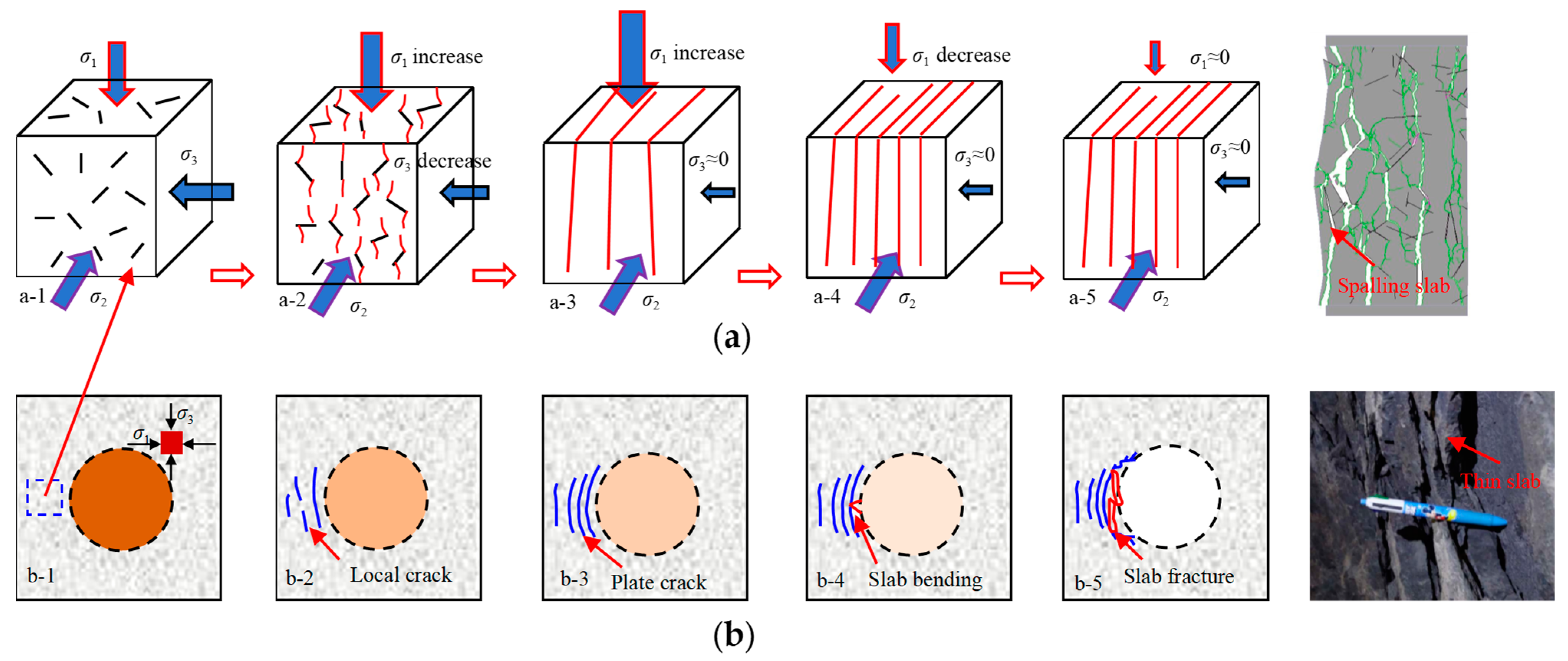
5.2. Fracture Mechanism of Hard Brittle Rocks

Spalling failure is a typical failure mode observed in hard brittle rocks in deep underground engineering construction and has been systematically explored, with the most representative ones being studies on the fracture problem of marble in the Jinping II Hydropower Station deep-buried diversion tunnel and LdB granite in the URL of AECL. Although the in situ stress and buried depth of these underground caverns are much higher than those of the underground caverns of the Baihetan Hydropower Station, the universality and severity of the spalling failure in marble or granite are not as common as those in basalt. This contradictory relationship may be due to the structures of the rock itself. Therefore, the results of this study are compared with two typical hard brittle rocks in terms of the failure characteristics, structural characteristics, and failure mechanisms, as shown in Figure 19, to understand the fracture problem of brittle rocks more comprehensively and systematically [50,51,52].
A rock is a typical heterogeneous material at the grain scale, typically including geometric heterogeneity caused by changes in the grain spatial distributions, shapes, and sizes; mechanical inhomogeneity due to variations in the grain densities, stiffness, and strength; and initial defect structures such as grain boundaries, cleavages, microcracks, and pores. The grain-scale structural characteristics control the meso-mechanical behavior of the grain itself, such as the crack evolutions, stress fields, and displacement fields, thereby controlling the macro-mechanical behavior of the entire rock, such as the deformation, strength, and failure characteristics [53]. As shown in Figure 19a, for cryptocrystalline basalts with an intergranular–intergranular structure, the main mineral components are feldspar, vitreous, pyroxene, and chlorite; the particle shapes are stripped, columnar, and granular; and the particles are extremely small (≤0.1 mm on average), without any microcracks inside or between them, indicative of a good grain-scale uniformity. However, due to the existence of hidden cracks, the homogeneity of basalt at the rock block scale is poor. For granite mainly composed of quartz, feldspar, and mica and for marble mainly composed of dolomite and calcite, with a granular structure, the particle shape is interlocking polygonal, the particles are large (approximately 0.5 mm on average), and there are evident microcracks inside or between the grains, indicative of significant grain-scale heterogeneity. The meso-structural characteristics of various brittle rocks are significantly different and are strongly associated with their diagenetic mechanisms. This structural difference is bound to have an important influence on the rock failure characteristics and mechanism.
The splitting failure is a typical failure mode for hard brittle rocks under uniaxial compression, such as marble, granite, and sandstone, showing flaky or plate rock slices after failure, as shown in Figure 19b. This failure mode is related to the grain-scale heterogeneity. Intact basalt is dominated by a fragmentation failure mode under uniaxial compression, showing rock fragments after failure; that is, the fragmentation failure is the most evident feature of cryptocrystalline basalt that makes it different from other brittle rocks. This failure mode is related to its good grain-scale homogeneity. Affected by the locations, number, sizes, and angles of hidden cracks, basalt with local hidden cracks can be dominated by tension failure, tension–shear composite failure, or shear failure, that is, the initial local hidden cracks play a leading role. In particular, when the sample size is large (i.e., 300–500 mm), the basalt block with sufficient hidden cracks at the REV size is dominated by a splitting failure mode, consistent with that of other hard brittle rocks. The structural properties of basalt change significantly with the increase in the sample size, with the continuous decrease in the homogeneity, and the failure mode also changes accordingly, consistent with other hard brittle rocks.
For the Jinping II hydropower station deep-buried diversion tunnel and the URL of AECL, as shown in Figure 19c, the in situ stress is extremely high, with the maximum principal stress being 60–65 MPa, the rocks are dense and hard, the fractures are not well developed, showing good homogeneity, and the rock strengths are high, with the UCS values of granite and marble being approximately 200 MPa and 100 MPa, respectively. Under this condition, the brittle failure problem of the surrounding rock mass is significant, which is mainly the spalling failure in the roof and floor or two sides of the underground caverns. This site failure situation is analogous to the axial splitting failure characteristics under uniaxial compression observed in laboratory tests, which is mainly a tensile failure mechanism of stress type under extremely high in situ stresses. For the underground caverns of the Baihetan Hydropower Station, the in situ stress is medium to high, with the maximum principal stress being in the range of 19–23 MPa, the rock is hard and dense, and the rock strength is extremely high, with the UCS being approximately 200 MPa, resulting in a relatively low stress-to-strength ratio. This indicates that the basalt cannot fail under the existing conditions. However, in addition to the large-scale structural planes, such as joints, faults, and dislocation zones, found in the basalt rock mass, small-scale hidden cracks generally exist with an evident heterogeneity. Consequently, the spalling failure of the surrounding rock mass during the underground cavern excavation is noticeable, indicating a contradictory relationship between the low rock mass strength and extremely high rock strength. The in situ failure condition is evidently different from the fragmentation failure of intact basalt under uniaxial compression observed in laboratory tests, and it is similar to the splitting failure of basalt blocks at the REV size under uniaxial compression, which is mainly a tensile failure mechanism characterized by stress–structure coupling.
In summary, basalt is significantly different from LdB granite and marble in terms of structural characteristics, failure characteristics, and failure mechanism. On a small scale (i.e., laboratory test), cryptocrystalline basalt is homogeneous, showing a fragmentation failure mode under uniaxial compression, while the heterogeneity of marble and granite is significant, exhibiting a splitting failure mode under uniaxial compression; that is, the meso-structural characteristics of the rock itself play a leading role. On a large scale (i.e., engineering site), basalt generally contains hidden cracks, with a prominent heterogeneity, and the surrounding rock mass near the excavation faces shows spalling failure, while granite and marble are relatively intact, with a good homogeneity, and the surrounding rock mass near the excavation faces also shows spalling failure. Although both these rocks exhibit spalling failure, their internal failure mechanisms are different: one is a stress type, and the other is a stress–structure coupled type. The previous understanding of the mechanical behavior of brittle rocks can no longer support the safety control of the surrounding rock mass in the underground caverns in Baihetan Hydropower Station, bringing significant challenges to the engineering design and construction. Hence, it is important to explore the basalt failure characteristics and mechanism in this study.

6. Conclusions

In this study, an SRM model combining FDEM and DFN models was used to systematically explore the size effect of the mechanical properties of basalt containing hidden cracks and the fracture evolution laws of the surrounding rock mass during the excavation of underground caverns. The failure mechanisms of hard brittle rocks represented by basalt under high stresses were comprehensively revealed. The main conclusions are as follows:
  • The SRM model was established by combining an FDEM model representing an intact matrix and a DFN model generated based on the statistical characteristics of the geometric parameters of hidden cracks. It represents an important method for efficiently and accurately studying the mechanical properties of hard brittle rocks with complex structures.
  • The obtained REV size of basalt blocks containing hidden cracks was 0.5 m. With the increase in the sample size, the mechanical properties as reflected in the stress–strain curve changed from elastic–brittle to elastic–plastic or ductile, the strength failure criterion changed from linear to nonlinear, and the failure modes changed from fragmentation failure to local structure-controlled failure and then to splitting failure. The essence of the rock size effect is its own structural effect, influenced by external conditions, such as the confining pressure, temperature, and loading rate, indicating that it is crucial to consider the real structural features of rocks to understand their mechanical behaviors.
  • The surrounding rock mass during excavation in the Baihetan Hydropower Station mainly exhibited a spalling failure mode, closely related to the complex structural characteristics of basalt and high in situ stresses; that is, a tensile fracture mechanism characterized by stress–structure coupling. The nucleation process of typical failure behaviors (e.g., spalling, rock-bursts) in deep underground engineering has a certain relationship with the fracture evolution of surrounding rocks at different depths, and they have a certain degree of synergy. Therefore, it is important to understand the fracture evolution laws of surrounding rocks during excavation to reveal the failure mechanism and formulate control measures.
  • This study has some limitations. On the one hand, the main focus was on basalt blocks with small-scale hidden cracks. There was less focus on basalt rock mass with engineering-scale hard structural planes, such as random joints and faults. On the other hand, this study mainly focused on the size effect analysis of the rock mechanical properties with a given distribution characteristic of the structural planes, without considering the effect of the change in the structural plane under different geometric parameters on the REV and corresponding mechanical properties. Related research will be performed in future work.

Author Contributions

C.D. contributed to the methodology, investigation, funding acquisition, and formal analysis. Z.L. contributed to the conceptualization, resources, and project administration. X.M. contributed to the software and validation. S.O. contributed to the data curation. All authors contributed to the writing—review and editing. All authors have read and agreed to the published version of the manuscript.

Funding

This work was supported by the National Natural Science Foundation of China (52309123), the Special Fund of Chinese Central Government for Basic Scientific Research Operations in Commonweal Research Institutes (CKSF2023310/YT, CKSF2023319/YT), and Open Research Fund of State Key Laboratory of Geomechanics and Geotechnical Engineering, Institute of Rock and Soil Mechanics, Chinese Academy of Sciences (SKLGME023013).

Institutional Review Board Statement

Not applicable.

Informed Consent Statement

Not applicable.

Data Availability Statement

The datasets generated within the scope of the current study are available from the corresponding author on reasonable request.

Acknowledgments

The authors acknowledge the assistance of Guojian Cui.

Conflicts of Interest

The authors declare no conflicts of interest.

Nomenclature

DFNDiscrete fracture network
FDEMFinite-discrete element method
SRMSynthetic rock mass
REVRepresentative elementary volume
UCSUnconfined compressive strength
BDSBrazilian basic splitting strength
P21Areal fracture intensity
σ3Confining stress
σ1σ3Deviatoric stress
ρBulk density
EYoung’s modulus
νPoisson’s ratio
φInternal friction angle
cCohesive strength
ftTensile strength
KIcMode I fracture toughness
Gf1Mode I fracture energy
Gf2Mode II fracture energy
PnNormal contact penalty
PtTangential contact penalty
PfFracture penalty
εAxial strain
ε3Lateral strain

References

  1. Peng, J.B.; Cui, P.; Zhuang, J.Q. Challenges to engineering geology of Sichuan—Tibet railway. Chin. J. Rock Mech. Eng. 2020, 39, 2377–2389. (In Chinese) [Google Scholar]
  2. Feng, X.T.; Yang, C.X.; Kong, R.; Zhao, J.; Zhou, Y.Y.; Yao, Z.B.; Hu, L. Excavation-induced deep hard rock fracturing: Methodology and applications. J. Rock Mech. Geotech. Eng. 2022, 14, 1–34. [Google Scholar] [CrossRef]
  3. He, M.C.; Wang, Q.; Wu, Q.Y. Innovation and future of mining rock mechanics. J. Rock Mech. Geotech. Eng. 2021, 13, 1–21. [Google Scholar] [CrossRef]
  4. Zhao, Y.S. Retrospection on the development of rock mass mechanics and the summary of some unsolved centennial problems. Chin. J. Rock Mech. Eng. 2021, 40, 1297–1336. (In Chinese) [Google Scholar]
  5. Liu, T.T.; Zhang, C.; Li, X.P.; Xu, K.; Xu, M.N.; Wang, Z.X. Triaxial experimental study of mechanical behavior of non-persistent jointed granite subjected to slight cyclic dynamic disturbances. Theor. Appl. Fract. Mec. 2024, 130, 104254. [Google Scholar] [CrossRef]
  6. Zhao, C.X.; Zhang, Z.X.; Wang, S.F.; Lei, Q.H. Effects of fracture network distribution on excavation-induced coupled responses of pore pressure perturbation and rock mass deformation. Comput. Geotech. 2022, 145, 104670. [Google Scholar] [CrossRef]
  7. Bahaaddini, M.; Sharrock, G.; Hebblewhite, B.K. Numerical investigation of the effect of joint geometrical parameters on the mechanical properties of a non-persistent jointed rock mass under uniaxial compression. Comput. Geotech. 2013, 49, 206–225. [Google Scholar] [CrossRef]
  8. Wang, X.; Cai, M. A DFN–DEM Multi-scale Modeling Approach for Simulating Tunnel Excavation Response in Jointed Rock Masses. Rock Mech. Rock Eng. 2020, 53, 1053–1077. [Google Scholar] [CrossRef]
  9. Hamdi, P.; Stead, D.; Elmo, D. Characterizing the influence of stress-induced microcracks on the laboratory strength and fracture development in brittle rocks using a finite-discrete element method-micro discrete fracture network FDEM-μDFN approach. J. Rock Mech. Geotech. Eng. 2015, 7, 609–625. [Google Scholar] [CrossRef]
  10. Software, R. ELFEN User’s Manual. Swansea, UK. 2004. Available online: http://www.rockfield.co.uk (accessed on 15 March 2023).
  11. Mahabadi, O.K.; Grasselli, G.; Munjiza, A. Y-GUI: A graphical user interface and pre-processor for the combined finite-discrete element code, Y2D, incorporating material heterogeneity. Comput. Geotech. 2010, 36, 241–252. [Google Scholar] [CrossRef]
  12. Lisjak, A.; Grasselli, G. A review of discrete modeling techniques for fracturing processes in discontinuous rock masses. J. Rock Mech. Geotech. Eng. 2014, 6, 301–314. [Google Scholar] [CrossRef]
  13. Bahrani, N.; Kaiser, P.K. Numerical investigation of the influence of specimen size on the unconfined strength of defected rocks. Comput. Geotech. 2016, 77, 56–67. [Google Scholar] [CrossRef]
  14. Farahmand, K.; Vazaios, I.; Diederichs, M.S.; Vlachopoulos, N. Investigating the scale-dependency of the geometrical and mechanical properties of a moderately jointed rock using a synthetic rock mass (SRM) approach. Comput. Geotech. 2018, 95, 162–179. [Google Scholar] [CrossRef]
  15. Xu, W.J.; Zhang, H.Y. Research on the effect of rock content and sample size on the strength behavior of soil-rock mixture. Bull. Eng. Geol. Environ. 2021, 80, 2715–2726. [Google Scholar] [CrossRef]
  16. Asadi, P.; Ashrafi, M.J.; Fakhimi, A. Physical and numerical evaluation of effect of specimen size on dynamic tensile strength of rock. Comput. Geotech. 2022, 142, 104538. [Google Scholar] [CrossRef]
  17. Bahaaddini, M.; Hagan, P.C.; Mitra, R.; Hebblewhite, B.K. Scale effect on the shear behaviour of rock joints based on a numerical study. Eng. Geol. 2014, 181, 212–223. [Google Scholar] [CrossRef]
  18. Zhou, Z.Q.; Sun, J.W.; Lai, Y.B.; Wei, C.C.; Hou, J.; Bai, S.S.; Huang, X.X.; Liu, H.L.; Xiong, K.Q.; Cheng, S. Study on size effect of jointed rock mass and influencing factors of the REV size based on the SRM method. Tunn. Undergr. Sp. Tech. 2022, 127, 104613. [Google Scholar] [CrossRef]
  19. Martin, C.D.; Read, R.S.; Martino, J.B. Observations of brittle failure around a circular test tunnel. Int. J. Rock Mech. Min. Sci. 1997, 34, 1065–1073. [Google Scholar] [CrossRef]
  20. Cai, M.; Kaiser, P.K.; Tasaka, Y.; Maejima, T.; Morioka, H.; Minami, M. Generalized crack initiation and crack damage stress thresholds of brittle rock masses near underground excavations. Int. J. Rock Mech. Min. Sci. 2004, 41, 833–847. [Google Scholar] [CrossRef]
  21. Feng, X.T.; Zhou, Y.Y.; Jiang, Q. Rock mechanics contributions to recent hydroelectric developments in China. Int. J. Rock Mech. Min. Sci. 2019, 11, 511–526. [Google Scholar] [CrossRef]
  22. Zhang, C.Q.; Zhou, H.; Feng, X.T. An index for estimating the stability of brittle surrounding rock mass: FAI and its engineering application. Rock Mech. Rock Eng. 2011, 44, 401–414. [Google Scholar] [CrossRef]
  23. Zhang, Z.R.; Wu, S.C.; Cheng, H.Y.; Han, L.Q.; Zhong, G.; Zhang, J. Rockburst simulation tests on structural plane of deep high-stress circular tunnels: A true triaxial test study on several different hard rocks. Theor. Appl. Fract. Mec. 2024, 132, 104473. [Google Scholar] [CrossRef]
  24. Lin, Q.B.; Cao, P.; Meng, J.J.; Cao, R.H.; Zhao, Z.Y. Strength and failure characteristics of jointed rock mass with double circular holes under uniaxial compression: Insights from discrete element method modelling. Theor. Appl. Fract. Mec. 2020, 109, 102692. [Google Scholar] [CrossRef]
  25. Bewick, R.P. The Strength of Massive to Moderately Jointed Rock and its Application to Cave Mining. Rock Mech. Rock Eng. 2021, 54, 3629–3661. [Google Scholar] [CrossRef]
  26. Vazaios, I.; Vlachopoulos, N.; Diederichs, M.S. Assessing fracturing mechanisms and evolution of excavation damaged zone of tunnels in interlocked rock masses at high stresses using a finite discrete-element approach. J. Rock Mech. Geotech. Eng. 2019, 11, 701–722. [Google Scholar] [CrossRef]
  27. Zhao, D.C.; Xia, Y.J.; Zhang, C.Q.; Tang, C.A.; Zhou, H.; Liu, N.; Singh, H.K.; Zhao, Z.X.; Chen, J.; Mu, C.Q. Failure modes and excavation stability of large-scale columnar jointed rock masses containing interlayer shear weakness zones. Int. J. Rock Mech. Min. Sci. 2022, 159, 105222. [Google Scholar] [CrossRef]
  28. Han, G.; Zhou, H.; Hou, J.; Zhang, C.S.; Singh, H.K.; Gao, Y. A comprehensive investigation on the shear properties of interlayer shear weakness zones. Bull. Eng. Geol. Environ. 2021, 80, 8765–8787. [Google Scholar] [CrossRef]
  29. Bubeck, A.; Walker, R.J.; Healy, D.; Dobbs, M.; Holwell, D.A. Pore geometry as a control on rock strength. Earth Planet. Sci. Lett. 2017, 457, 38–48. [Google Scholar]
  30. Zhang, C.Q.; Liu, Z.J.; Pan, Y.B.; Gao, Y.; Zhou, H.; Cui, G.J. Influence of amygdale on crack evolution and failure behavior of basalt. Eng. Fract. Mech. 2020, 226, 106843. [Google Scholar] [CrossRef]
  31. Liu, Z.J.; Zhang, C.Q.; Zhang, C.S.; Gao, Y.; Zhou, H.; Chang, Z.R. Deformation and failure characteristics and fracture evolution of cryptocrystalline basalt. J. Rock Mech. Geotech. Eng. 2019, 11, 990–1003. [Google Scholar] [CrossRef]
  32. Liu, Z.J.; Wang, H.B.; Zhou, B. Effect of natural defects on the fracture behaviors and failure mechanism of basalt through mesotesting and FDEM modeling. Eng. Fract. Mech. 2022, 271, 108598. [Google Scholar] [CrossRef]
  33. Liu, Z.J.; Wang, H.B.; Zhang, C.Q.; Zhou, B.; Zhou, H. Size dependences of the mechanical behaviors of basalt rock blocks with hidden joints analyzed using a hybrid DFN–FDEM model. Eng. Fract. Mech. 2021, 258, 108078. [Google Scholar] [CrossRef]
  34. Zhang, W.; Chen, J.P.; Liu, C.; Huang, R.; Li, M.; Zhang, Y. Determination of geometrical and structural representative volume elements at the Baihetan dam site. Rock Mech. Rock Eng. 2012, 45, 409–419. [Google Scholar] [CrossRef]
  35. Dai, F.; Li, B.; Xu, N.W.; Fan, Y.L.; Zhang, C.Q. Deformation forecasting and stability analysis of large-scale underground powerhouse caverns from microseismic monitoring. Int. J. Rock Mech. Min. Sci. 2016, 86, 269–281. [Google Scholar] [CrossRef]
  36. Wang, M.; Li, H.B.; Han, J.Q.; Xiao, X.H.; Zhou, J.W. Large deformation evolution and failure mechanism analysis of the multi-freeface surrounding rock mass in the Baihetan underground powerhouse. Eng. Fail. Anal. 2019, 100, 214–226. [Google Scholar] [CrossRef]
  37. Sun, Q.H.; Li, S.J.; Guo, H.S.; Zheng, M.Z.; Yang, Z.Y. In situ test of excavation damaged zone of columnar jointed rock masses under different borehole conditions. Bull. Eng. Geol. Environ. 2021, 80, 2991–3007. [Google Scholar] [CrossRef]
  38. Xia, Y.J.; Zhang, C.Q.; Zhou, H.; Hou, J.; Su, G.S.; Gao, Y.; Liu, N.; Singh, H.K. Mechanical behavior of structurally reconstructed irregular columnar jointed rock mass using 3D printing. Eng. Geol. 2020, 268, 105509. [Google Scholar] [CrossRef]
  39. Shi, A.C.; Li, C.J.; Hong, W.B.; Lu, G.D.; Zhou, J.W.; Li, H.B. Comparative analysis of deformation and failure mechanisms of underground powerhouses on the left and right banks of Baihetan hydropower station. J. Rock Mech. Geotech. Eng. 2022, 14, 731–745. [Google Scholar] [CrossRef]
  40. Hu, Z.H.; Wu, B.B.; Xu, N.W.; Wang, K. Effects of discontinuities on stress redistribution and rock failure: A case of underground caverns. Tunn. Undergr. Sp. Tech. 2022, 127, 104583. [Google Scholar] [CrossRef]
  41. Geomechanica Inc. Irazu 2D Geomechanical Simulation Software, Version 3.1; Geomechanica Inc.: Toronto, ON, Canada, 2017; Available online: http://www.geomechanica.com/software (accessed on 20 December 2022).
  42. Tatone, B.S.A.; Grasselli, G. A calibration procedure for two-dimensional laboratory-scale hybrid finite–discrete element simulations. Int. J. Rock Mech. Min. Sci. 2015, 75, 56–72. [Google Scholar] [CrossRef]
  43. Zhang, C.S.; Chu, W.J.; Liu, N.; Zhu, Y.S.; Hou, J. Laboratory tests and numerical simulations of brittle marble and squeezing schist at Jinping II hydropower station. China J. Rock Mech. Geotech. Eng. 2011, 3, 30–38. [Google Scholar] [CrossRef]
  44. Renani, H.R.; Cai, M. Forty-year review of the Hoek–Brown failure criterion for jointed rock masses. Rock Mech. Rock Eng. 2022, 55, 439–461. [Google Scholar] [CrossRef]
  45. Jiang, Q.; Feng, X.T.; Fan, Y.L.; Fan, Q.X.; Liu, G.F.; Pei, S.F.; Duan, S.Q. In situ experimental investigation of basalt spalling in a large underground powerhouse cavern. Tunn. Undergr. Sp. Tech. 2017, 68, 82–94. [Google Scholar] [CrossRef]
  46. Zhao, J.S.; Jiang, Q.; Lu, J.F.; Chen, B.R.; Pei, S.F.; Wang, Z.L. Rock fracturing observation based on microseismic monitoring and borehole imaging: In situ investigation in a large underground cavern under high geostress. Tunn. Undergr. Sp. Tech. 2022, 126, 104549. [Google Scholar] [CrossRef]
  47. Hoek, E.; Brown, E.T. Underground Excavations in Rock; Institution of Mining and Metallurgy: London, UK, 1980. [Google Scholar]
  48. Guan, R.; Peng, J.; Yao, M.D.; Jiang, Q.H.; Wong, L.N.Y. Effects of specimen size and thermal-damage on physical and mechanical behavior of a fine-grained marble. Eng. Geol. 2018, 232, 46–55. [Google Scholar]
  49. Liu, Z.J.; Zhang, C.S.; Zhang, C.Q.; Wang, H.B.; Zhou, H.; Zhou, B. Effects of amygdale heterogeneity and sample size on the mechanical properties of basalt. J. Rock Mech. Geotech. Eng. 2022, 14, 93–107. [Google Scholar] [CrossRef]
  50. Read, R.S. 20 years of excavation response studies at AECL’s underground research laboratory. Int. J. Rock Mech. Min. Sci. 2004, 41, 1251–1275. [Google Scholar] [CrossRef]
  51. Zhang, C.S.; Liu, N.; Chu, W.J. Key technologies and risk management of deep tunnel construction at Jinping II hydropower station. J. Rock Mech. Geotech. Eng. 2016, 8, 499–512. [Google Scholar] [CrossRef]
  52. Xiao, Y.X.; Feng, X.T.; Feng, G.L.; Liu, H.J.; Jiang, Q.; Qiu, S.L. Mechanism of evolution of stress–structure controlled collapse of surrounding rock in caverns: A case study from the Baihetan hydropower station in China. Tunn. Undergr. Sp. Tech. 2016, 51, 56–67. [Google Scholar] [CrossRef]
  53. Hoek, E.; Martin, C.D. Fracture initiation and propagation in intact rock-A review. J. Rock Mech. Geotech. Eng. 2014, 6, 287–300. [Google Scholar] [CrossRef]
Figure 1. Layout of the underground caverns at Baihetan Hydropower Station, where 1–4 represent the main powerhouse, main transformer chamber, headgate chamber, and tailrace surge chamber, respectively, and I–X represent the excavation sequences of the cross section of the underground powerhouse from top to bottom [39]. (a) Location of the study area; (b) layout of underground caverns; (c) 3D visualization of left-bank underground caverns; (d) right-bank underground caverns.
Applsci 14 09069 g001
Figure 2. Structural characteristics of basalt and in situ failure features of surrounding rock mass in the underground caverns at Baihetan Hydropower Station [40]. (a) Geological longitudinal section of the left-bank underground powerhouse; (b) basalt block with hidden cracks; (c) fracture morphologies at engineering site.
Applsci 14 09069 g002
Figure 3. Meso-structural characteristics of cryptocrystalline basalt. (a) Polarizing microscopy image of a thin section; (b) CT scanning images.
Applsci 14 09069 g003
Figure 4. Physical forms and sketches of basalt blocks with hidden cracks obtained from the underground caverns at Baihetan Hydropower Station.
Applsci 14 09069 g004
Figure 5. Statistical distribution characteristics of the geometric parameters of hidden cracks in a basalt block. (a) Crack length; (b) crack orientation.
Applsci 14 09069 g005
Figure 6. Element mesh and constitutive models of crack elements in an FDEM model [41]. (a) Element mesh in an FDEM model; (b) cohesive model for mode I; (c) slip-weakening model for mode II; (d) I–II mixed mode.
Applsci 14 09069 g006
Figure 7. SRM (DFN–FDEM) models of a basalt block of different sizes with hidden cracks. (a) DFN models of different sizes; (b) SRM model with dimensions of 300 mm × 600 mm.
Applsci 14 09069 g007
Figure 8. Numerical basalt samples with a standard size for meso-parameter calibration. (a) DFN models under uniaxial and triaxial compression; (b) DFN models under Brazilian disc splitting; (c) SRM models under uniaxial and triaxial compression (left) and Brazilian disc splitting (right).
Applsci 14 09069 g008
Figure 9. FDEM model configuration of the left-bank underground powerhouse at Baihetan Hydropower Station.
Applsci 14 09069 g009
Figure 10. Effects of the sample size on the mechanical parameters of basalt with hidden cracks. (a) Uniaxial compression strength, UCS; (b) tensile strength, BDS; (c) cohesive strength, c; (d) internal friction angle, φ.
Applsci 14 09069 g010
Figure 11. Effects of the sample size on the stress–strain curve characteristics of basalt with hidden cracks under different confining pressures. (a) Intact specimen at a size of 50 mm; (b) specimen with local cracks at a size of 100 mm; (c) specimen with many cracks at a size of 300 mm; (d) specimen with sufficient cracks at a size of 500 mm.
Applsci 14 09069 g011
Figure 12. Compressive strength of different-sized basalt samples with hidden cracks under different confining pressures. (a) Relationship between sample size and compressive strength; (b) relationship between confining pressure and compressive strength.
Applsci 14 09069 g012
Figure 13. Fracture evolution and failure modes of basalt samples of different sizes with hidden cracks under uniaxial compression. (a) Fragmentation failure of intact basalt; (b) structure-controlled failure of medium-sized basalt with local fractures; (c) splitting failure of REV-sized basalt with sufficient fractures.
Applsci 14 09069 g013
Figure 14. Typical failure characteristics of a intact basalt rock mass of the underground powerhouse during excavation at Baihetan Hydropower Station [45].
Applsci 14 09069 g014
Figure 15. Typical failure characteristics of a jointed basalt rock mass of the underground powerhouse during excavation at Baihetan Hydropower Station [45]. (a) Spatial form of spalling failure; (b) Sketch of spalling failure; (c) Enlarged diagram of failure modes; (d) Thin slab after spalling failure.
Applsci 14 09069 g015
Figure 16. Fracture evolution process of the intact basalt rock mass during different excavation stages of each layer of the left-bank underground powerhouse: the maximum principal stress fields (denoted by σ1), displacement fields (denoted by S), crack evolutions (S, T-S, and T represent shear, tensile–shear, and tensile cracks, respectively), and in situ monitoring or existing research results, respectively [46]. (a) Excavation of the middle pilot tunnel of the first layer; (b) first expansion excavation of both sides of the first layer; (c) expansion excavation of the floor of the first layer; (d) second expansion excavation of both sides of the first layer; (e) excavation of the fourth layer; (f) excavation of the seventh layer; (g) excavation completion.
Applsci 14 09069 g016aApplsci 14 09069 g016b
Figure 17. Progressive fracture process and failure mechanisms of the intact basalt rock mass during excavation in underground caverns. (a) Stress state change within the surrounding rock mass near excavation surface; (b) Crack evolution process within the surrounding rock mass near excavation face.
Applsci 14 09069 g017
Figure 18. Influence of specimen size on the UCS [47,48,49].
Applsci 14 09069 g018
Figure 19. Structural characteristics and failure modes of several different types of hard brittle rocks, including basalt (left), marble (middle), and granite (right) [50,51,52]. (a) Polarized microscopy images of a thin section of different types of hard brittle rocks; (b) failure modes of different types of hard brittle rocks under uniaxial compression; (c) failure modes of different types of hard brittle rock mass on site.
Applsci 14 09069 g019
Table 1. Mechanical parameters of a basalt block used in the FDEM model.
Mechanical ParametersMatrixHidden CrackRock Block
Bulk density, ρ (kg/m3)2900.00 2800.00
Poisson’s ratio, ν0.15 0.25
Young’s modulus, E (GPa)50.00 30.00
Internal friction angle, φ (°)40.0025.0047.50
Cohesive strength, c (MPa)75.0015.0012.50
Tensile strength, ft (MPa)18.504.007.15
Mode-I fracture energy, Gf1 (N/m)100.0020.0020.00
Mode-II fracture energy, Gf2 (N/m)1000.00200.00200.00
Normal contact penalty, Pn (GPa·m)500.0010.00300.00
Tangential contact penalty, Pt (GPa/m)500.0010.00300.00
Fracture penalty, Pf (GPa)500.0010.00300.00
Table 2. Macro-mechanical parameters of basalt with a standard size obtained by testing and FDEM modeling.
TypeE (GPa)c (MPa)φ (°)UCS (MPa)BDS (MPa)
Simulation45.0852.1546.81231.6722.71
49.8882.6339.78328.4621.66
48.5322.7835.7280.8922.37
43.2337.846.55161.0922.51
40.1233.5642.6140.3416.33
47.6825.3340.5764.2323.67
35.4632.4747.08150.7913.84
49.8882.6339.78330.2121.16
49.8882.6339.78330.2121.16
49.8882.6339.78330.2121.16
Average45.9653.4641.85214.8120.66
Test45.82 57.44 41.16 197.01 18.50
Disclaimer/Publisher’s Note: The statements, opinions and data contained in all publications are solely those of the individual author(s) and contributor(s) and not of MDPI and/or the editor(s). MDPI and/or the editor(s) disclaim responsibility for any injury to people or property resulting from any ideas, methods, instructions or products referred to in the content.

