Abstract
In this paper, we explore the benefits of using a magnetostrictive component in a variable reluctance energy harvester. The intrinsic magnetic field bias and the possibility to utilize magnetic force to achieve pre-stress leads to a synergetic combination between this type of energy harvester and magnetostriction. The proposed energy harvester system, to evaluate the concept, consists of a magnetostrictive cantilever beam with a cubic magnet as proof mass. Galfenol, Fe81.6Ga18.4, is used to implement magnetostriction. Variable reluctance is achieved by fixing the beam parallel to an iron core, with some margin to create an air gap between the tip magnet and core. The mechanical forces of the beam and the magnetic forces lead to a displaced equilibrium position of the beam and thus a pre-stress. Two configurations of the energy harvester were evaluated and compared. The initial configuration uses a simple beam of aluminum substrate and a layer of galfenol with an additional magnet fixing the beam to the core. The modified design reduces the magnetic field bias in the galfenol by replacing approximately half of the length of galfenol with aluminum and adds a layer of soft magnetic material above the galfenol to further reduce the magnetic field bias. The initial system was found to magnetically saturate the galfenol at equilibrium. This provided the opportunity to compare two equivalent systems, with and without a significant magnetostrictive effect on the output voltage. The resonance frequency tuning capability, from modifying the initial distance of the air gap, is shown to be maintained for the modified configuration (140 Hz/mm), while achieving RMS open-circuit coil voltages larger by a factor of two (2.4 V compared to 1.1 V). For a theoretically optimal load, the RMS power was simulated to be 5.1 mW. Given the size of the energy harvester (18.5 cm3) and the excitation acceleration (0.5 g), this results in a performance metric of 1.1 mW/cm3g2.
1. Introduction
Energy harvesters provide a useful alternative to traditional sources of energy for low-power electronics. The purpose of an energy harvester is to generate electrical power by energy conversion from the local environment. While the source of energy is available, the energy harvester generates power, excluding the need for bulky power wiring or battery replacement. This can enable increased cost effectiveness and/or energy efficiency for current applications. Truly self-sufficient electronics can also rewrite certain design requirements and make completely new applications possible, e.g., in the wearable electronics [1,2], IoT [3], automotive [4], medical implants [5] and railway [6] fields. Renewable energies based on energy harvesting are key solutions for ‘green’ energy sources and for sustainable IoT and WSN devices. This is seen in the roadmap and forecast [7] as well as in the European Union R&D programs [8,9].
This article will focus on addressing certain challenges for energy harvesters which make use of the kinetic energy provided by vibrations. This type of energy harvester is called a vibrational energy harvester (VEH). A number of different physical effects have to date been utilized to convert movement to energy. These typically include piezoelectricity, electrostatics, electromagnetic induction and triboelectricity [10,11,12]. In this article, we focus on conversion by magnetic induction [13]. Such an energy harvester is often called an electromagnetic energy harvester (EMEH). Most VEHs consist of a mass-spring-damper system utilizing the resonance effect to increase the amount of power which can be extracted, within a certain range of vibration frequency. As it is increasingly difficult to achieve a low resonance frequency as the system size decreases, these systems are typically challenged in achieving high performance under the condition of small size and low vibration frequency.
High performance in this regard refers to high output voltage, high output power and large bandwidth in the frequency response. A high output voltage mitigates losses in the signal processing circuitry. A high output power and wide bandwidth will improve the VEH’s capability of enabling applications in general.
There are a number of methods, used in research, to overcome these challenges. Multi-modal VEHs make use of multiple bending modes, each with an increasingly larger resonance frequency, to increase the system bandwidth [14,15,16,17,18,19]. In non-resonant VEHs, the moving mass is not connected to any type of spring. There is, in this case, no performance peak at a certain frequency. However, this facilitates achieving greater performance at very low frequencies, below 10 Hz, as well as a relatively large bandwidth in this region [20,21]. Nonlinear techniques can be used to modify the frequency range. Some examples of these are based on implementing bi-stability, stoppers, spring non-linearity or non-linear damping [22,23,24,25,26]. As described in [27], an EH operating at anti-resonance can benefit from increased output voltage and input-to-output efficiency.
Another approach to increasing bandwidth is to implement resonance frequency tuning. A number of techniques are described in the review by [28], which include sliding mass, sliding fixed point, stiffness control (via, e.g., PZT patch), magnetic force modulation (via, e.g., variable reluctance), etc. Other examples are using electrostatic force [29,30] or pre-buckling [31,32].
Research on vibrational energy harvesting using magnetostrictive components stems from the discovery of room-temperature giant magnetostrictive materials (such as Terfenol-D [33] and later galfenol). The work by Flateu et al. [34] (with ship hull vibrations in mind) provides an early example of galfenol use in vibrational energy harvesting. Since then, there have been several publications on both magnetostrictive cantilever beam VEHs [35,36,37,38] and magnetostrictive rod type VEHs [39,40]. The review by Dapino et al. from 2017 [41] gives an overview of VEHs using different magnetostrictive materials in both rod and beam configurations. Fumio et al. [42] published a review in 2018, including other transduction types, providing an interesting comparison.
Ducharne et al. have in their research [43,44] evaluated and compared energy harvesting using various magnetostrictive materials. Their conclusion is that, given sufficient magnetic biasing, Terfenol D and galfenol provide the best performance.
From 2019 to 2022, Rasilo et al. published several papers dealing with the modeling of galfenol rods [45,46,47,48,49] and galfenol cantilever beam energy harvesting [50]. Thermodynamic constitutive laws and an equivalent stress model are implemented within the finite element modeling (FEM) simulation tool COMSOL, and a linearized small signal model is developed and evaluated. The simulation results are shown to correspond well with measurements.
Similarly, Davino et al. published several papers describing and modeling magnetostrictive energy harvesters. Davino et al. primarily took an equivalent circuit approach to develop a (non-linear) model for the VEH voltage and power output. In [51], such a model is implemented in COMSOL. Following the equivalent circuit approach, Davino et al. explored circuit designs with active control to maximize the converted voltage and power (i.e., the rectified and voltage converted signal) [52,53,54]. Davino also provides an example of utilizing magnetostriction for energy harvesting in a vehicle suspension system [55].
In this work, we build upon the concept of a variable reluctance EH, as described in [25]. The EH comprises a magnetic circuit, including a variable air gap. The components making up the path to one side of the gap are essentially rigid, while the components for the “return” path have significant elasticity. Both paths are connected at one end and separated at the other by an air gap. In this way, the gap size is coupled to external vibrations. Given the harmonic vibrations of the EH, the dynamic oscillation of the elastic components, relative to the static parts, will depend on material properties (elasticity and mechanical damping), mass and magnetic forces acting to close the air gap. It is vital that the reluctance of the air gap is significant compared to the reluctance of the total magnetic circuit; any additional static reluctance will decrease performance. An important benefit to using this method is that the induced voltage is not only a function of the vibration rate, but also of the area of the air gap.
In this work, we will explore the effect of adding additional magneto-mechanical coupling through magnetostriction. We provide a proof of concept for a novel energy harvesting mechanism, synergistically combining magnetostriction with variable reluctance in an electromagnetic energy harvester to increase power output without significantly increasing the size of the energy harvester.
The aim of this paper consists of two parts. First, to provide experimental data and equivalent simulated data (based on FEM, with a model equivalent to the VEH under measurement). Second, to use the FEM to find a solution closer to optimum. The scope consists of describing the experimental setup, procedure and results; describing the simulation model and results; discussing the results based on comparisons and drawing conclusions from the results and discussions. Deriving an analytical solution, which would be less accurate than FEM simulations yet less computationally heavy, may provide additional insights but is outside the scope of this paper.
In this paper, we will give a detailed description of the proposed energy harvester design (Section 2.1) and its working principles (Section 2.2). We describe the tools used to evaluate these principles, in the form of a simulation model (Section 2.3) and a corresponding prototype (Section 2.4). The results gained from these tools are discussed (Section 3.1) and compared with state-of-the-art energy harvesters (Section 3.2). In conclusion, we summarize the key takeaways and briefly describe the next possible steps for this specific research.
2. Experimental Methods
2.1. Magnetic Energy Harvester Design
To evaluate the proposed concept, a simple magnetic circuit including a bi-layer beam is implemented. The primary components of the resulting VEH consist of a magnetic core, magnets, coil, and magnetostrictive beam, configured as shown in Figure 1. The core components are shown in gray and represent a material of high magnetic permeability. Two magnets, oriented in a constructive manner, provide the necessary magnetic flux in the air gap and magnetic biasing of the system [39]. A beam, consisting of one layer of non-magnetic material and one layer of magnetostrictive material, acts as the elastic part of the system. One of the magnets, placed at the end of the beam, acts also as proof mass. The magnetostrictive material is on the “bottom” side of the beam (shown as purple in Figure 1).
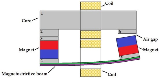
Figure 1.
Cross-section of the proposed energy harvester design, with iron core (gray), neodymium magnets (blue/red), aluminum substrate (green) and galfenol magnetostrictive layer (purple). Iron core components are numbered, 1 to 6, and are referred to in the main text.
Either one large coil or two differentially coupled coils can be used (an example of the latter is given in Figure 1). The dimensions of the core components can be reduced under the condition that the stiffness is large, and the magnetic reluctance of the air gap is still significant. The optimal thickness and length of the beam layers depend on the intended use. The neutral axis of the beam should always be in the substrate region, or else the magnetostrictive layer will experience tension and compression simultaneously, leading to a canceling effect.
2.2. Concept Theory
As described in [25], The VEH will have a stable equilibrium state, resulting from the attractive force in the air gap and the restoring force from the elastic components. The total restoring force is the difference between these two forces. The attractive magnetic force has a non-linear square dependency [56] on the flux in the air gap while the mechanical spring force from the elastic components is linear (for small displacement). For ease of description, we have added Figure 2, which shows the relevant features of linear curves intersecting a square curve. The three linear curves in Figure 2 represent the restoring mechanical spring force for three, decreasing, initial air gap distances, i.e., the air gap size when the beam is horizontal. Using Figure 2 as a simplified example, stable equilibrium states are obtained at the points marked by dots. Unstable equilibria are marked by arrows. The equilibrium state can be adjusted by modifying the initial distance of the air gap. As this initial distance is decreased, the linear curve in Figure 2 moves to the left and the point of stable equilibria is found at a smaller air gap distance. As the system experiences a harmonic external force excitation, the beam will oscillate around its stable equilibrium.
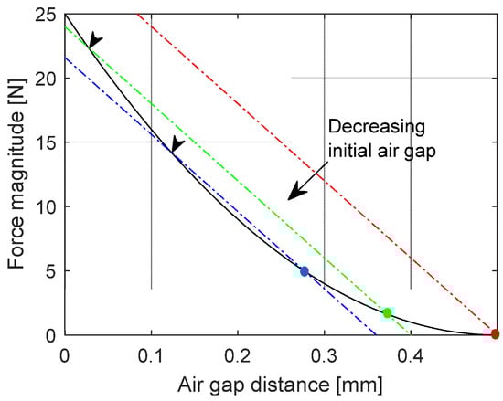
Figure 2.
Hypothetical linear and square-dependent forces representing an ideal version of the system described in this work. Dashed lines correspond to the mechanical spring force at three different initial air gaps. The solid line corresponds to the magnetic force. Dots represent stable equilibria and arrows represent unstable equilibria.
The total restoring force experienced by the proof mass, while oscillating, will differ depending on the equilibrium state, leading to differences in frequency response. The closer the linear spring force tangents of the square magnetic force, the smaller the restoring force becomes, thus leading to a lower resonance frequency. This comes at the cost of a smaller oscillation allowed before the magnetic force dominates (i.e., the point indicated by an arrow is passed) and the air gap is permanently closed.
In this work, we include the effects from magnetostriction, which lead to altered magnetization [57] due to strain (Villari effect), and mechanical strain due to magnetization (Joule effect). The Villari effect can in this case make it possible to achieve larger time variations in the magnetic field (in the region of the magnetostrictive material) as the beam oscillates, while the Joule effect can have a beneficial effect on the beam displacement.
We choose to use galfenol as magnetostrictive material, as its favorable characteristics [34,39] have made it a common choice for use in vibration energy harvesters making use of magnetostriction. Galfenol has the benefit of having a significant magnetostriction (λs~200 ppm) and being easy to machine (as it is ductile). A layer of galfenol is in this case glued to the elastic beam. The magnetostriction constant for galfenol is positive [57,58], which results in an increase in magnetization with positive stress (tension) and an increase in strain with an applied magnetic field. For this reason, the magnetostrictive layer of the beam is on the bottom side, which experiences tension when the air gap decreases.
As mentioned, the magnets provide a magnetic field bias for the system. Both a magnetic field and stress bias are required for an optimal performance of magnetostrictive components. As can be seen from the magnetization and strain vs. applied magnetic field curves in [57,59], for a certain pre-stress, there is a region of the applied magnetic field that has the largest variation in strain and magnetization. For the concept described here, it is beneficial if the magnetic field variations, in the magnetostrictive component, resulting from the varying reluctance of the air gap, are within this region of maximum strain/magnetization variation. Similarly, depending on the magnetic field bias point, there is a pre-stress which allows for the largest variation in magnetization and strain. In this case, the variable reluctance concept, utilizing an air gap, leads to a displaced beam at equilibrium and thus provides a stress bias in the magnetostrictive component.
2.3. FEM Model
In this work, we use a finite element modeling tool (COMSOL Multiphysics 6.2), with a geometry equivalent to Figure 1 and suitably chosen material properties (Table 1). COMSOL includes the necessary physics modules to account for stress, strain, magnetic fields and resulting forces as well as the effect of magnetostriction (both Joule and Villari effects). To reduce computation time, we use a 2D model (2D modeling of a magnetostrictive beam has been shown to be sufficiently accurate, compared to 3D modeling [35]). Magnetic flux is in this case only in-plane and induced currents (eddy currents) are only out-of-plane. A global out-of-plane thickness is specified in the software, thus allowing cross-sectional flux and accompanying forces to be calculated.

Table 1.
Material properties used in COMSOL. Definitions: E = Young’s modulus, MS = magnetization saturation, σ = electrical conductivity, ρ = density, λS = saturation magnetostriction, and N/A = not applicable with this specific COMSOL model.
Material-dependent B-H curves are used when modeling the magnetic fields within the core components. The magnets are modeled with a remanent flux density of 1.18 T. The magnetic field in the magnetostrictive component is modeled non-linearly using the Langevin function [60] of an effective magnetic field, which is the sum of the applied magnetic field and the magnetic field due to stress in the magnetostrictive material. The material properties used in the model are based on soft magnetic steel for the core components, neodymium for the magnets, aluminum for the substrate and galfenol for the magnetostrictive component. Mechanical damping is included as Rayleigh damping, with mass damping assumed to be negligible [50] and a stiffness damping of 10−5, corresponding to a damping ratio of 0.0081. The electrical conductivity of the core corresponds to that of iron, allowing for eddy currents. These currents reduce performance by creating a counteracting magnetic field and damping of the system [60]. These effects are small for low frequencies and can typically be significantly mitigated using laminated cores. Numerical damping, resulting from the FEM time-stepping algorithm, is minimized by choosing the generalized α method and setting “α” to 0.97.
The key output from the FEM simulations is the frequency response of the energy harvester, with regard to open-circuit coil voltage. Although the simulation is carried out in 2D, the expected coil voltage can be estimated from the derivative of the flux. The flux used for the voltage calculation is the average of flux in a 10 mm × 10 mm × 10 mm region of the core, close to the air gap. As the output is assumed to be non-linear, a frequency domain simulation cannot be used. Instead, time domain simulations are performed for a number of frequencies in the region of interest. Each simulation corresponds to 60 oscillations of the system. To exclude any initial transient behavior, we use only the second half of the time domain data, from which the RMS voltage for each frequency is determined.
2.4. Prototype and Measurement Setup
The design of the prototype is based on the same components and geometry as shown in Figure 1. The core components are made of soft magnetic steel (cold drawn s235jr), the beam substrate is aluminum, the magnets are made of neodymium (energy grade N36) and the magnetostrictive material is galfenol (Fe81.6Ga18.4). Additionally, a shaker fixture, coil bobbins and a fixture to hold the bobbins are 3D-printed in polyamide (PA2200). The coil bobbins are wound with 0.1 mm copper wire, with 3200 turns. The dimensions of the magnets are 10 mm × 10 mm × 10 mm. The core components all have the same cross-sectional dimensions of 10 mm × 10 mm. To simplify the explanation, we have numbered each of the separate core components in Figure 1. Parts 3–5 are identical, with a height of 2.5 mm, and are glued to the magnets. Parts 2 and 6 are exchangeable and have been fabricated with various heights, from 1.5 mm to 4 mm. The length of part 1 is 53 mm. The lengths of the substrate and magnetostrictive beam are also 53 mm. Each layer of the beam is 1 mm thick, i.e., the beam’s total thickness is 2 mm. The beam components are glued together (with a very thin layer of liquid metal). Threaded, and non-threaded, holes allow for all parts to be screwed together. The screws used are magnetic, yet their permeability is unknown. The coil bobbins are glued to a fixture which fits tightly around core part 1. Figure 3 shows the manner in which the components are assembled (Figure 3a) and the assembled prototype (Figure 3b). An overview of the VEH properties is given in Table 2.
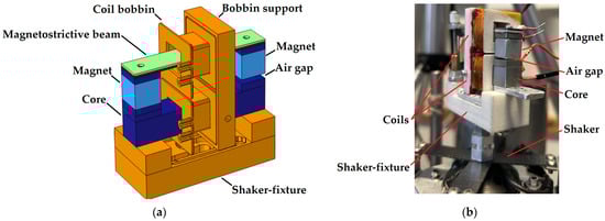
Figure 3.
(a) The 3D CAD of COMSOL model geometry, with iron (dark blue), neodymium (light blue), aluminum (dark red), galfenol (green) and polyamide (orange). (b) Prototype for lab measurements. The energy harvester is here mounted on top of the shaker.
Table 2.
Prototype physical properties.
Two M5 screws are used to fix the energy harvester to the shaker fixture and a single M5 fixes the shaker fixture to the shaker. The fixture-to-shaker mounting hole is extended in one direction to allow for balancing of the system.
The hardware for the measurement setup consists of a shaker (2007E, Modal Shop, Cincinnati, OH, USA), Laser Doppler Vibrometer (LDV, OFV 056, Polytec, Waldbronn, Germany), controllable current source, digital oscilloscope, waveform generator (Analog Discovery 3, AD3, Digilent, Pullman, WA, USA) and laptop. The current source, which drives the shaker, is controlled by a waveform from the AD3. The LDV measures the velocity at a position on the energy harvester. The measured velocity is output as a voltage signal from the LDV, which is measured by the AD3. The output from the induction coil is also measured by the AD3 on a high impedance (1 MΩ) input, thus resulting in the open-circuit voltage of the energy harvester.
The measurement procedure consists of driving the shaker over a range of frequencies while measuring the LDV output. A script is implemented with the software (WaveForms 3.21.3) running the AD3, which converts the LDV signal to an equivalent acceleration value and modulates the amplitude of the driving signal (to current source), ensuring that the measured acceleration is constant over the frequency range. The base acceleration amplitude is ensured to be 0.5 g (±1%) for all frequencies.
If the system is unbalanced on the shaker, it will lead to unpredictable behavior of the measured frequency response and control signal; in part due to this, the LDV measures only at a single point. To determine if this is the case or not, an additional component was added which allowed for the velocity of the shaker fixture to be measured along its longest dimension. If the measured velocity is essentially the same for all measurement points along this dimension (for a set of frequencies in the relevant range), then it is assumed to be balanced.
A series of frequency sweeps were performed, each with a different configuration of the energy harvester. For each sweep, the thickness of core part 6 (see Figure 1) was increased (replacing the part with a corresponding yet thicker piece). The thickness of the core parts is in increments of 0.5 mm. To allow for smaller increments, steel shims of 0.1 mm thickness were used. The thickness of part 2 was kept at 3.5 mm. This procedure was repeated until the air gap force was too large, at which point the magnet was permanently stuck to the core (unless manually removed). For ease of description, we use “β” as the term for the thickness of part 6 (see Figure 1). The initial air gap distance, in millimeters, equals 6—β.
3. Results and Discussion
3.1. Comparing Measurements with Simulations
Figure 4 shows the simulated and measured frequency dependencies of the open-circuit output voltage from a coil around the long core component (part 1 in Figure 1) of the energy harvester. The simulated data also contain a set where the magnetostrictive effect is removed by setting the saturation magnetostriction, λS, to 0. Both measured and simulated data show resonance at approximately 195 Hz, at β = 3 mm. As β increases, the resonance frequency decreases following the description in Section 2.2.
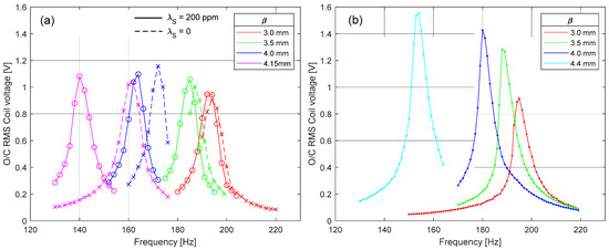
Figure 4.
RMS of the open-circuit coil voltage. Curves from right to left result from using an increasingly thicker spacer, i.e., increasing β. (a) Simulated values. Circles and crosses are data points. Solid lines correspond to using λS = 200 and dashed lines for λS = 0. (b) Measured on prototype. Dots are data points. Lines are for visual aid.
For both measurements and simulations, β is increased from 3.0 mm in steps of 0.5 mm. Using β = 4.5 mm results in a permanently closed air gap at equilibrium for both the lab prototype and simulation model. The last data set therefore corresponds to the maximum β, which can be used before the air gap is permanently closed. We found this maximum β to be 4.15 mm for the simulation model and 4.4 for the lab prototype. A likely explanation for this difference is that the total system reluctance of the lab prototype is larger than that of the simulation model (due to glue gaps). This would also explain the smaller resonance frequency tuning in the measured data, as compared to simulated frequency (see Figure 4a,b).
Both sets of data show a non-linear relationship between resonance frequency and β, with the highest sensitivity at large β. Comparing the simulated frequency response, with λS = 0 and λS = 200 ppm (Figure 4a), magnetostriction does not contribute to the voltage amplitude, but increases the sensitivity of resonance frequency shift when decreasing the air gap.
According to the simulated data of Figure 5b, most of the magnetostrictive material is probably close to magnetic saturation (see MS for galfenol in Table 1). Comparing the magnetic field data with the von Mises stress data of Figure 5a, only small coupling can be seen. Thus, we conclude that the effect of magnetostriction is here primarily an additional strain bias, which increases beam elasticity, an effect also known as the ΔE effect [61]. The additional strain also reduces the equilibrium air gap distance, which in turn further reduces the resonance frequency (as described in Section 2.2).
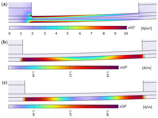
Figure 5.
Simulation results, for the original design, in the vicinity of the magnetostrictive component. (a) von Mises stress distributions. (b) Magnetization, λS = 200. (c) Magnetization, λS = 0.
For large air gap distances (β = 3 mm and β = 3.5 mm), the measured and simulated frequency responses fit well (see Figure 4a,b). As the air gap diminishes, the discrepancy between measured and simulated data, with regard to resonance frequency, increases. We assume the beams’ mechanical properties to be correctly modeled, i.e., that the natural frequencies are essentially equal for both the modeled and measured system. As we do not measure the material properties of the prototype, there is a possibility that the material parameter values used in the COMSOL model differ from the physical prototype, leading to different output characteristics. However, as the magnetostrictive material is magnetically saturated in this case (see Figure 5b), the effect from errors in modeled magnetostrictive properties should be small. Thus, the discrepancy is likely explained by a larger total reluctance of the system (e.g., due to thick layers of glue), leading to smaller coupling between the air gap distance and flux (and equivalently force).
The main point of this paper is however to determine if magnetostriction can have a synergetic effect with the dynamics of the energy harvester. The equilibrium state of the energy harvester should therefore correspond to a magnetic field bias, of the magnetostrictive part, that is far from saturation but still provides sufficient bias. To achieve this, an alternative design (Figure 6) is evaluated through numerical simulation.
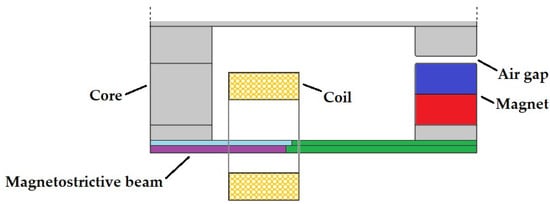
Figure 6.
Revised design. Compared to the original design, one magnet is removed, while the neodymium magnet (blue/red) acting as proof mass remains. The beam composition consists of cobalt steel Vacoflux 50 (light blue), galfenol (purple) and aluminum (green). The iron core components (gray) are identical to the original design.
Maintaining the overall design, the magnetic bias is reduced by removing one magnet and replacing a portion of the magnetostrictive material with aluminum. A soft magnetic material (cobalt steel Vacoflux 50, from the COMSOL materials library, in the light blue region of Figure 6) is also used to further reduce the magnetic field within the magnetostrictive material. The thickness of the galfenol layer is here 1.2 mm. The total thickness of the beam is maintained at 2 mm. From Figure 7b, it can be seen that the simulation now gives a significantly lower magnetic bias in the magnetostrictive material. Comparing the distribution of magnetization (Figure 7b) and stress (Figure 7a), the magnetization is significantly higher in the region of larger stress. This indicates stronger dynamic coupling between stress and the magnetic field as compared to the previous design. Figure 7c shows the magnetization with saturation magnetostriction set to zero.
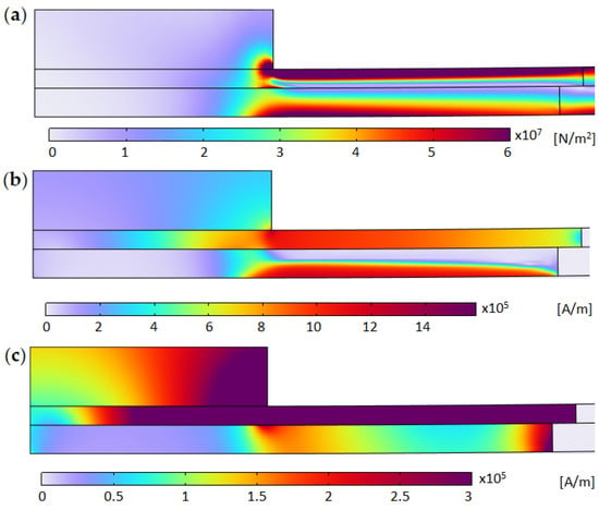
Figure 7.
Simulation results, for the modified design, in the vicinity of magnetostrictive component. (a) von Mises stress distributions. (b) Magnetization, λS = 200. (c) Magnetization, λS = 0.
For the new design, simulations showed the largest flux variations to be in the region of the magnetostrictive component. Figure 8 shows the open-circuit coil voltages derived from these flux variations. The variation in RMS voltage at resonance shows interesting behavior as the air gap distance is decreased (i.e., increasing β). The RMS voltage increases sharply between a β of 4.5 mm and 4.7 mm, from 1 V to 2.4 V (a factor of two of the RMS voltage from the original design), where after there is a sharp decrease in voltage. The reason for this behavior is not fully determined but it may be that the magnetic field bias and pre-stress resulting from using a spacer thickness, β, of 4.7 mm is optimal for this specific design. Overall, the RMS voltage at resonance is 50% larger compared to the original design.
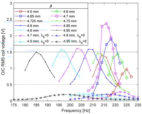
Figure 8.
RMS of the simulated open-circuit coil voltage for the modified design. Curves from right to left result from increasing values of β. Circles, dots and crosses are data points. Lines are added as visual aid. Solid lines correspond to using λS = 200 and dashed lines for λS = 0.
The optimum load (regarding power output) is typically defined as that which matches the impedance of the VEH; this is not strictly correct [27] but is likely close to optimum. The impedance matched load equals , where and are the inductance and resistance of the coil. β = 4.7 mm; the excitation frequency, , was 216 Hz; the optimal load was 495 Ω, and the theoretically optimum RMS power was found to be 5.1 mW in simulation (assuming the load voltage is approx. half the open-circuit voltage and rectification loss is neglected).
The flux variations in the core were found to be smaller (e.g., generating 0.8 V peak at β = 4.8 mm) compared to the previous design. This is not unexpected as one magnet is used instead of two, and a large portion of the magnetic materials in the beam are replaced by aluminum in the new design, likely leading to less coupling between the beam displacement and flux in the core.
The tuning sensitivity is comparable with the initial design. For the modified design, the tuning sensitivity is on average 140 Hz/mm in the range of β from 4.75 mm to 4.95 mm. For the initial design, it is 160 Hz/mm in the range of β from 4.0 mm to 4.15 mm. As for the initial design, the results using λS = 0 show less tunability. As there is no magnetostriction, the voltage amplitude is expected to be low.
From Figure 9, the non-linear behavior of the output voltage can be seen. For β > 4.7 mm, the non-linearity decreases, and the curve gradually becomes more sinusoidal. The curves closely resemble those shown by Deng et al. [35] for cantilever magnetostrictive beams of varying composition and damping.
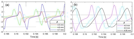
Figure 9.
Simulated O/C RMS coil voltage at resonance and at the end of the time series. (a) β from 4.5 mm to 4.7 mm. (b) β from 4.8 mm to 4.95 mm.
An optimal magnetostrictive effect is generally achieved for a certain magnetization bias and pre-stress [39,62,63]. For the energy harvester designs described in this work, magnetization bias and pre-stress are coupled by the air gap distance, reluctance and force. Thus, optimization with regard to the magnetostrictive effect is a complex process which is not attempted here. As described, measures were taken to reduce magnetic bias. From the simulations, it was determined that only removing either magnet was insufficient in reducing the magnetic field bias in the magnetostrictive component to reasonable levels. Removing one magnet and using a shorter segment of galfenol (less than half the original length) also did not solve the issue.
To find the optimal design, a number of geometry and material properties must be considered, such as magnet energy grade, thickness, length and material type of the beam components and the dimension of the core components. As an example, an increase of 0.8 V in output voltage (RMS) was noted when decreasing the length magnetostrictive component by 1 mm (β = 4.8 mm).
An intrinsic flaw in the design of this energy harvester is the magnets themselves, as they introduce a large reluctance. A large total system reluctance will result in a small relative change in reluctance due to the air gap variations, and thus small variations in flux and induced voltage amplitude.
We determine the composite beam’s mechanical properties by running a simulation with an initial transient and free oscillations thereafter. Magnetic fields and magnetostriction are in this case deactivated. Applying the logarithmic decrement method, we find the damping ratios to be 0.0081 and 0.0088 for the two designs described above. From the same simulations, the natural frequency is found to be 227 Hz for the design in Figure 1 and 273 Hz for the design in Figure 7.
The effects of hysteresis are inherently included in the measurement data. The similarity between simulated and measured curves in Figure 4 indicates that magnetic hysteresis has a minor effect in our case.
3.2. Comparison to State of the Art
Comparing vibrational energy harvesters is a complex task as many different parameters must be considered relative to a specific application area. For a comparison to be relevant, size, weight, considered frequency range, excitation acceleration, displacement range and complexity should be comparable.
Based on a set of 21 articles (sum of reviewed articles in [28,64]), the highest relative resonance frequency tunability achieved was 112% [65] (defined as the natural frequency divided by the tuning range), but with only relatively low power (μW range). The tuning is mechanical and the necessary travel distance to produce the acquired tunability is large, 34 mm in total and 2.8 Hz/mm on average, leading to a bulky tuning system. In [66], a similar tunability is achieved but at magnitudes of larger power (mW range). The required travel distance is again mechanical and still large, 13 mm in total and 1 Hz/mm on average. A similar example can be found in [67].
Feng et al. [29] apply tuning via electrostatic force, allowing for compact design. Both tunability and power are relatively low. Bjurström et al. [25] show a theoretically high mechanical tuning sensitivity (420 Hz/mm on average) but with output power still in the μW range (for low acceleration).
4. Conclusions
The use of magnetostriction synergistically combines with variable reluctance energy harvesters by making use of the intrinsic magnetic field bias and pre-stress and producing a larger output voltage than would otherwise have been possible. We compare two equivalent variable reluctance VEHs, with and without significant magnetostriction, and find comparable tunability but potentially larger RMS voltages by a factor of two for the system utilizing magnetostriction.
The simulation results in this work show a moderate mechanical tuning sensitivity (140 Hz/mm) and relatively high-power output (5.1 mW) achieved at a low base acceleration (0.5 g). Coupled with a relatively small size, the commonly used metric mW/cm3g2 is at a reasonable level of 1.1. The short beam length and light proof mass lead to relatively large resonance frequencies and thus low tunability relative to the natural frequency. Optimization of the geometry, coils and material choice can likely improve performance.
The increase in RMS voltage at β = 4.6 mm and 4.7 mm is indicative of a local optimum, likely regarding magnetic field bias and pre-stress, although this requires further investigation.
Although the geometry and design are not optimized regarding power, the achieved performance is promising, and merits continued development using magnetostriction in unison with variable reluctance energy harvesters.
The next step in this research is to develop a more efficient numerical solver based on a lumped mechanical and equivalent electric circuit model. This would enable a rigorous search of a large parameter space and provide insight into the key factors for an optimal design.
Author Contributions
J.B.: Conceptualization, methodology, software, validation, visualization, investigation, data curation, writing—original draft, formal analysis. C.R.: conceptualization, methodology, supervision, resources, project administration, funding acquisition. C.J.: conceptualization, methodology, writing—review and editing. All authors have read and agreed to the published version of the manuscript.
Funding
This work received funding from Swedish Foundation for Strategic Research in the program for ‘Research Institute PhD’ (grant no. FID16-0055) and from ECSEL Joint Undertaking (JU) project ‘Energy ECS’ (grant no. 101007247). The APC was funded by RISE Research Institutes of Sweden AB.
Institutional Review Board Statement
Not applicable.
Informed Consent Statement
Not applicable.
Data Availability Statement
The original contributions presented in the study are included in the article, further inquiries can be directed to the corresponding author/s.
Conflicts of Interest
The authors declare that they have no known competing financial interests or personal relationships that could have appeared to influence the work reported in this paper.
References
- Ali, A.; Shaukat, H.; Bibi, S.; Altabey, W.A.; Noori, M.; Kouritem, S.A. Recent progress in energy harvesting systems for wearable technology. Energy Strategy Rev. 2023, 49, 101124. [Google Scholar] [CrossRef]
- Zhang, H.; Shen, Q.; Zheng, P.; Wang, H.; Zou, R.; Zhang, Z.; Pan, Y.; Zhi, J.; Xiang, Z. Harvesting Inertial Energy and Powering Wearable Devices: A Review. Small Methods 2024, 8, e2300771. [Google Scholar] [CrossRef] [PubMed]
- Liu, L.; Guo, X.; Liu, W.; Lee, C. Recent Progress in the Energy Harvesting Technology—From Self-Powered Sensors to Self-Sustained IoT, and New Applications. Nanomaterials 2021, 11, 2975. [Google Scholar] [CrossRef] [PubMed]
- Bentouba, S.; Zioui, N.; Breuhaus, P.; Bourouis, M. Overview of the Potential of Energy Harvesting Sources in Electric Vehicles. Energies 2023, 16, 5193. [Google Scholar] [CrossRef]
- Jiang, D.; Shi, B.; Ouyang, H.; Fan, Y.; Wang, Z.L.; Li, Z. Emerging Implantable Energy Harvesters and Self-Powered Implantable Medical Electronics. ACS Nano 2020, 14, 6436–6448. [Google Scholar] [CrossRef] [PubMed]
- Hosseinkhani, A.; Younesian, D.; Eghbali, P.; Moayedizadeh, A.; Fassih, A. Sound and vibration energy harvesting for railway applications: A review on linear and nonlinear techniques. Energy Rep. 2021, 7, 852–874. [Google Scholar] [CrossRef]
- He, X.; Das, R. Energy Harvesting for Electronic Devices 2020–2040; IDTechEx: Cambridge, UK, 2020. [Google Scholar]
- Energy Harvesting and Storage Technologies. Available online: https://cordis.europa.eu/programme/id/HORIZON_HORIZON-EIC-2021-TRANSITIONCHALLENGES-01-02 (accessed on 26 September 2024).
- Clean Energy Competitiveness. Available online: https://energy.ec.europa.eu/topics/research-and-technology/clean-energy-competitiveness_en (accessed on 26 September 2024).
- Prajwal, K.T.; Manickavasagam, K.; Suresh, R. A review on vibration energy harvesting technologies: Analysis and technologies. Eur. Phys. J. Spec. Top. 2022, 231, 1359–1371. [Google Scholar] [CrossRef]
- Karan, S.K.; Maiti, S.; Lee, J.H.; Mishra, Y.K.; Khatua, B.B.; Kim, J.K. Recent Advances in Self-Powered Tribo-/Piezoelectric Energy Harvesters: All-In-One Package for Future Smart Technologies. Adv. Funct. Mater. 2020, 30, 2004446. [Google Scholar] [CrossRef]
- Le, X.; Guo, X.; Lee, C. Evolution of Micro-Nano Energy Harvesting Technology—Scavenging Energy from Diverse Sources towards Self-Sustained Micro/Nano Systems. Nanoenergy Adv. 2023, 3, 101–125. [Google Scholar] [CrossRef]
- Muscat, A.; Bhattacharya, S.; Zhu, Y. Electromagnetic Vibrational Energy Harvesters: A Review. Sensors 2022, 22, 5555. [Google Scholar] [CrossRef]
- Yu, H.; Fan, L.; Shan, X.; Zhang, X.; Zhang, X.; Hou, C.; Xie, T. A novel multimodal piezoelectric energy harvester with rotating-DOF for low-frequency vibration. Energy Convers. Manag. 2023, 287, 117106. [Google Scholar] [CrossRef]
- Pertin, O.; Shrivas, P.; Guha, K.; Rao, K.S.; Iannacci, J. New and efficient design of multimode piezoelectric vibration energy harvester for MEMS application. Microsyst. Technol. 2021, 27, 3523–3531. [Google Scholar] [CrossRef]
- Qin, H.; Mo, S.; Jiang, X.; Shang, S.; Wang, P.; Liu, Y. Multimodal Multidirectional Piezoelectric Vibration Energy Harvester by U-Shaped Structure with Cross-Connected Beams. Micromachines 2022, 13, 396. [Google Scholar] [CrossRef] [PubMed]
- Xie, Z.; Liu, L.; Huang, W.; Shu, R.; Ge, S.; Xin, Y.; Chen, Z.; Lin, W. A multimodal E-shaped piezoelectric energy harvester with a built-in bistability and internal resonance. Energy Convers. Manag. 2023, 278, 116717. [Google Scholar] [CrossRef]
- Bouhedma, S.; Zheng, Y.; Lange, F.; Hohlfeld, D. Magnetic Frequency Tuning of a Multimodal Vibration Energy Harvester. Sensors 2019, 19, 1149. [Google Scholar] [CrossRef]
- Sun, R.; Li, Q.; Yao, J.; Scarpa, F.; Rossiter, J. Tunable, multi-modal, and multi-directional vibration energy harvester based on three-dimensional architected metastructures. Appl. Energy 2020, 264, 114615. [Google Scholar] [CrossRef]
- Zhao, H.; Ouyang, H.; Zhang, H. A nonresonant triboelectric-electromagnetic energy harvester via a vibro-impact mechanism for low-frequency multi-directional excitations. Nano Energy 2023, 107, 108123. [Google Scholar] [CrossRef]
- Liu, H.; Hou, C.; Lin, J.; Li, Y.; Shi, Q.; Chen, T.; Sun, L.; Lee, C. A non-resonant rotational electromagnetic energy harvester for low-frequency and irregular human motion. Appl. Phys. Lett. 2018, 113, 203901. [Google Scholar] [CrossRef]
- Yang, T.; Zhou, S.; Fang, S.; Qin, W.; Inman, D.J. Nonlinear vibration energy harvesting and vibration suppression technologies: Designs, analysis, and applications. Appl. Phys. Rev. 2021, 8, 031317. [Google Scholar] [CrossRef]
- Jia, Y. Review of nonlinear vibration energy harvesting: Duffing, bistability, parametric, stochastic and others. J. Intell. Mater. Syst. Struct. 2020, 31, 921–944. [Google Scholar] [CrossRef]
- Tran, N.; Ghayesh, M.H.; Arjomandi, M. Ambient vibration energy harvesters: A review on nonlinear techniques for performance enhancement. Int. J. Eng. Sci. 2018, 127, 162–185. [Google Scholar] [CrossRef]
- Bjurström, J.; Ohlsson, F.; Vikerfors, A.; Rusu, C.; Johansson, C. Tunable spring balanced magnetic energy harvester for low frequencies and small displacements. Energy Convers. Manag. 2022, 259, 115568. [Google Scholar] [CrossRef]
- Diala, U.; Zhu, Y.; Gunawardena, R. Investigative Study of the Effect of Damping and Stiffness Nonlinearities on an Electromagnetic Energy Harvester at Low-Frequency Excitations. Machines 2024, 12, 30. [Google Scholar] [CrossRef]
- Bjurström, J.; Ohlsson, F.; Rusu, C.; Johansson, C. Unified Modeling and Analysis of Vibration Energy Harvesters under Inertial Loads and Prescribed Displacements. Appl. Sci. 2022, 12, 9815. [Google Scholar] [CrossRef]
- Liu, X.; He, L.; Liu, R.; Hu, D.; Zhang, L.; Cheng, G. Piezoelectric energy harvesting systems using mechanical tuning techniques. Rev. Sci. Instrum. 2023, 94, 031501. [Google Scholar] [CrossRef]
- Feng, Y.; Zhou, Z.; Luo, H.; Wang, R.; Han, Y.; Xiong, Y. Frequency-tunable resonant hybrid vibration energy harvester using a piezoelectric cantilever with electret-based electrostatic coupling. IET Nanodielectrics 2023, 6, 46–56. [Google Scholar] [CrossRef]
- Ghanbari, M.; Rezazadeh, G.; Moloudpour-Tolkani, V. A wide-bandwidth MEMS energy harvester based on a novel voltage-sliding stiffness tunability. Appl. Math. Model. 2024, 125, 16–34. [Google Scholar] [CrossRef]
- Benhemou, A.; Gibus, D.; Huguet, T.; Morel, A.; Demouron, Q.; Saint-Martin, C.; Roux, E.; Charleux, L.; Badel, A. Predictive lumped model for a tunable bistable piezoelectric energy harvester architecture. Smart Mater. Struct. 2024, 33, 045033. [Google Scholar] [CrossRef]
- Lu, K.; Hu, R.; Wang, X.; Deng, Z. Multi-directional and ultra-low frequency energy harvester utilizing tunable buckled piezoelectric film. Mech. Syst. Signal Process. 2024, 210, 111137. [Google Scholar] [CrossRef]
- Hathaway, K.B.; Clark, A.E. Magnetostrictive Materials. MRS Bull. 1993, 18, 34–41. [Google Scholar] [CrossRef]
- Staley, M.E.; Flatau, A.B. Characterization of energy harvesting potential of Terfenol-D and Galfenol. In Smart Structures and Materials 2005: Smart Structures and Integrated Systems; Flatau, A.B., Ed.; SPIE: Bellingham, WA, USA, 2005; p. 630. [Google Scholar] [CrossRef]
- Deng, Z.; Dapino, M.J. Modeling and design of Galfenol unimorph energy harvesters. Smart Mater. Struct. 2015, 24, 125019. [Google Scholar] [CrossRef]
- Clemente, C.S.; Davino, D.; Loschiavo, V.P.; Visone, C. Non-Linear Modeling of a Bi-Layer Magnetostrictive Cantilever Considering ΔE Effect. J. Magn. Magn. Mater. 2024, 592, 171755. [Google Scholar] [CrossRef]
- Meng, A.; Yan, C.; Li, M.; Pan, W.; Yang, J.; Wu, S. Modeling and Experiments on Galfenol Energy Harvester. Acta Mech. Sin. 2020, 36, 635–643. [Google Scholar] [CrossRef]
- Ghodsi, M.; Ziaiefar, H.; Mohammadzaheri, M.; Al-Yahmedi, A. Modeling and Characterization of Permendur Cantilever Beam for Energy Harvesting. Energy 2019, 176, 561–569. [Google Scholar] [CrossRef]
- Berbyuk, V. Vibration energy harvesting using Galfenol-based transducer. In Active and Passive Smart Structures and Integrated Systems 2013; Sodano, H., Ed.; SPIE: Bellingham, WA, USA, 2013; p. 86881F. [Google Scholar] [CrossRef]
- Clemente, C.S.; Mahgoub, A.; Davino, D.; Visone, C. Multiphysics Circuit of a Magnetostrictive Energy Harvesting Device. J. Intell. Mater. Syst. Struct. 2017, 28, 2317–2330. [Google Scholar] [CrossRef]
- Deng, Z.; Dapino, M.J. Review of Magnetostrictive Vibration Energy Harvesters. Smart Mater. Struct. 2017, 26, 103001. [Google Scholar] [CrossRef]
- Narita, F.; Fox, M. A Review on Piezoelectric, Magnetostrictive, and Magnetoelectric Materials and Device Technologies for Energy Harvesting Applications. Adv. Eng. Mater. 2018, 20, 1700743. [Google Scholar] [CrossRef]
- Daniel, L.; Ducharne, B.; Liu, Y.; Sebald, G. Choosing the Best Magnetostrictive Material for Energy Harvesting Applications: A Simple Criterion Based on Ericsson Cycles. J. Magn. Magn. Mater. 2023, 587, 171281. [Google Scholar] [CrossRef]
- Liu, Y.; Lallart, M.; Ducharne, B.; Makihara, K.; Sebald, G. Analysis of Energy Conversion Capability among Various Magnetostrictive Materials for Energy Harvesting. Smart Mater. Struct. 2023, 32, 125004. [Google Scholar] [CrossRef]
- Mizukawa, Y.; Ahmed, U.; Zucca, M.; Blažević, D.; Rasilo, P. Small-Signal Modeling and Optimal Operating Condition of Magnetostrictive Energy Harvester. J. Magn. Magn. Mater. 2022, 547, 168819. [Google Scholar] [CrossRef]
- Ahmed, U.; Jeronen, J.; Zucca, M.; Palumbo, S.; Rasilo, P. Finite Element Analysis of Magnetostrictive Energy Harvesting Concept Device Utilizing Thermodynamic Magneto-Mechanical Model. J. Magn. Magn. Mater. 2019, 486, 165275. [Google Scholar] [CrossRef]
- Ahmed, U.; Aydin, U.; Zucca, M.; Palumbo, S.; Kouhia, R.; Rasilo, P. Modeling a Fe-Ga Energy Harvester Fitted with Magnetic Closure Using 3D Magneto-Mechanical Finite Element Model. J. Magn. Magn. Mater. 2020, 500, 166390. [Google Scholar] [CrossRef]
- Ahmed, U.; Aydin, U.; Daniel, L.; Rasilo, P. 3-D Magneto-Mechanical Finite Element Analysis of Galfenol-Based Energy Harvester Using an Equivalent Stress Model. IEEE Trans. Magn. 2021, 57, 7400405. [Google Scholar] [CrossRef]
- Palumbo, S.; Rasilo, P.; Zucca, M. Experimental Investigation on a Fe-Ga Close Yoke Vibrational Harvester by Matching Magnetic and Mechanical Biases. J. Magn. Magn. Mater. 2019, 469, 354–363. [Google Scholar] [CrossRef]
- Ahmed, U.; Blažević, D.; Mizukawa, Y.; Aydin, U.; Rasilo, P. Validation of thermodynamic magneto-mechanical finite-element model on cantilever-beam type magnetostrictive energy harvester. J. Magn. Magn. Mater. 2022, 564, 170098. [Google Scholar] [CrossRef]
- Clemente, C.S.; Davino, D.; Loschiavo, V.P. Analysis of a Magnetostrictive Harvester With a Fully Coupled Nonlinear FEM Modeling. IEEE Trans. Magn. 2021, 57, 4001204. [Google Scholar] [CrossRef]
- Clemente, C.S.; Davino, D.; Iannone, I.; Loschiavo, V.P. Experimental Characterization of an AC–DC Boost for Energy Harvesting Device Based on Magnetostrictive Materials. Electricity 2024, 5, 24–35. [Google Scholar] [CrossRef]
- Clemente, C.S.; Iannone, I.; Loschiavo, V.P.; Davino, D. Design and Optimization of a Boost Interface for Magnetostrictive Energy Harvesting. Appl. Sci. 2023, 13, 1606. [Google Scholar] [CrossRef]
- Iannone, I.; Clemente, C.S.; Davino, D.; Loschiavo, V.P. AC-DC Boost Modelling for Magnetostrictive Energy Harvesting. In Proceedings of the 2021 IEEE International Conference on Environment and Electrical Engineering and 2021 IEEE Industrial and Commercial Power Systems Europe (EEEIC/I&CPS Europe), Bari, Italy, 7–10 September 2021; IEEE: Piscataway, NJ, USA, 2021; pp. 1–6. [Google Scholar]
- Clemente, C.S.; Loschiavo, V.P.; Davino, D. Enhancing Electric Vehicle Comfort with Magnetostrictive Energy Harvesting. In Proceedings of the 2023 IEEE Vehicle Power and Propulsion Conference (VPPC), Milan, Italy, 24–27 October 2023; IEEE: Piscataway, NJ, USA, 2023; pp. 1–6. [Google Scholar]
- Riad, S.M.; Salama, I.M. Addendum 9C: Magnetic Forces in Air Gaps: Magnetic Pull, 1st ed.; McGraw-Hill Education: New York, NY, USA, 2020. [Google Scholar]
- Mahadevan, A.; Evans, P.G.; Dapino, M.J. Dependence of magnetic susceptibility on stress in textured polycrystalline Fe81.6Ga18.4 and Fe79.1Ga20.9 Galfenol alloys. Appl. Phys. Lett. 2010, 96, 012502. [Google Scholar] [CrossRef]
- Wun-Fogle, M.; Restorff, J.B.; Clark, A.E. Magnetostriction of Stress-annealed Fe-Ga and Fe-Ga-Al Alloys under Compressive and Tensile Stress. J. Intell. Mater. Syst. Struct. 2006, 17, 117–122. [Google Scholar] [CrossRef]
- Clark, A.; Wun-Fogle, M.; Restorff, J.B.; Lograsso, T.A. Magnetostrictive Properties of Galfenol Alloys Under Compressive Stress. Mater. Trans. 2002, 43, 881–886. [Google Scholar] [CrossRef]
- Dapino, M.J. Nonlinear and Hysteretic Magnetomechanical Model for Magnetostrictive Transducers. Ph.D. Thesis, Iowa State University, Digital Repository, Ames, IA, USA, 1999. [Google Scholar] [CrossRef]
- Scheidler, J.J.; Asnani, V.M.; Dapino, M.J. Design and testing of a dynamically-tuned magnetostrictive spring with electrically controlled stiffness. In Industrial and Commercial Applications of Smart Structures Technologies 2015; Farinholt, K.M., Griffin, S.F., Eds.; SPIE: Bellingham, WA, USA, 2015; p. 94330F. [Google Scholar] [CrossRef]
- Zhao, X.; Lord, D.G. Application of the Villari effect to electric power harvesting. J. Appl. Phys. 2006, 99, 08M703. [Google Scholar] [CrossRef]
- Davino, D.; Giustiniani, A.; Visone, C.; Adly, A.A. Energy Harvesting Tests With Galfenol at Variable Magneto-Mechanical Conditions. IEEE Trans. Magn. 2012, 48, 3096–3099. [Google Scholar] [CrossRef]
- Abdelazim, E.M.; Anis, Y.H.; Shaltout, M.L. Extremum seeking control of a self-tunable variable-inertia vibration energy harvester: Modeling and experimental validation. Energy Convers. Manag. 2024, 302, 118123. [Google Scholar] [CrossRef]
- Huang, S.-C.; Lin, K.-A. A novel design of a map-tuning piezoelectric vibration energy harvester. Smart Mater. Struct. 2012, 21, 085014. [Google Scholar] [CrossRef]
- Xia, H.; Chen, R.; Ren, L. Parameter tuning of piezoelectric–electromagnetic hybrid vibration energy harvester by magnetic force: Modeling and experiment. Sens. Actuators A Phys. 2017, 257, 73–83. [Google Scholar] [CrossRef]
- Sosna, P.; Rubeš, O.; Hadaš, Z. Verification and analysis of advanced tuneable nonlinear vibration energy harvester. Mech. Syst. Signal Process. 2023, 189, 110096. [Google Scholar] [CrossRef]
Disclaimer/Publisher’s Note: The statements, opinions and data contained in all publications are solely those of the individual author(s) and contributor(s) and not of MDPI and/or the editor(s). MDPI and/or the editor(s) disclaim responsibility for any injury to people or property resulting from any ideas, methods, instructions or products referred to in the content. |
© 2024 by the authors. Licensee MDPI, Basel, Switzerland. This article is an open access article distributed under the terms and conditions of the Creative Commons Attribution (CC BY) license (https://creativecommons.org/licenses/by/4.0/).