Evaluation of Cumulative Damage and Safety of Large-Diameter Pipelines under Ultra-Small Clear Distance Multiple Blasting Using Non-Electric and Electronic Detonators
Abstract
:1. Introduction
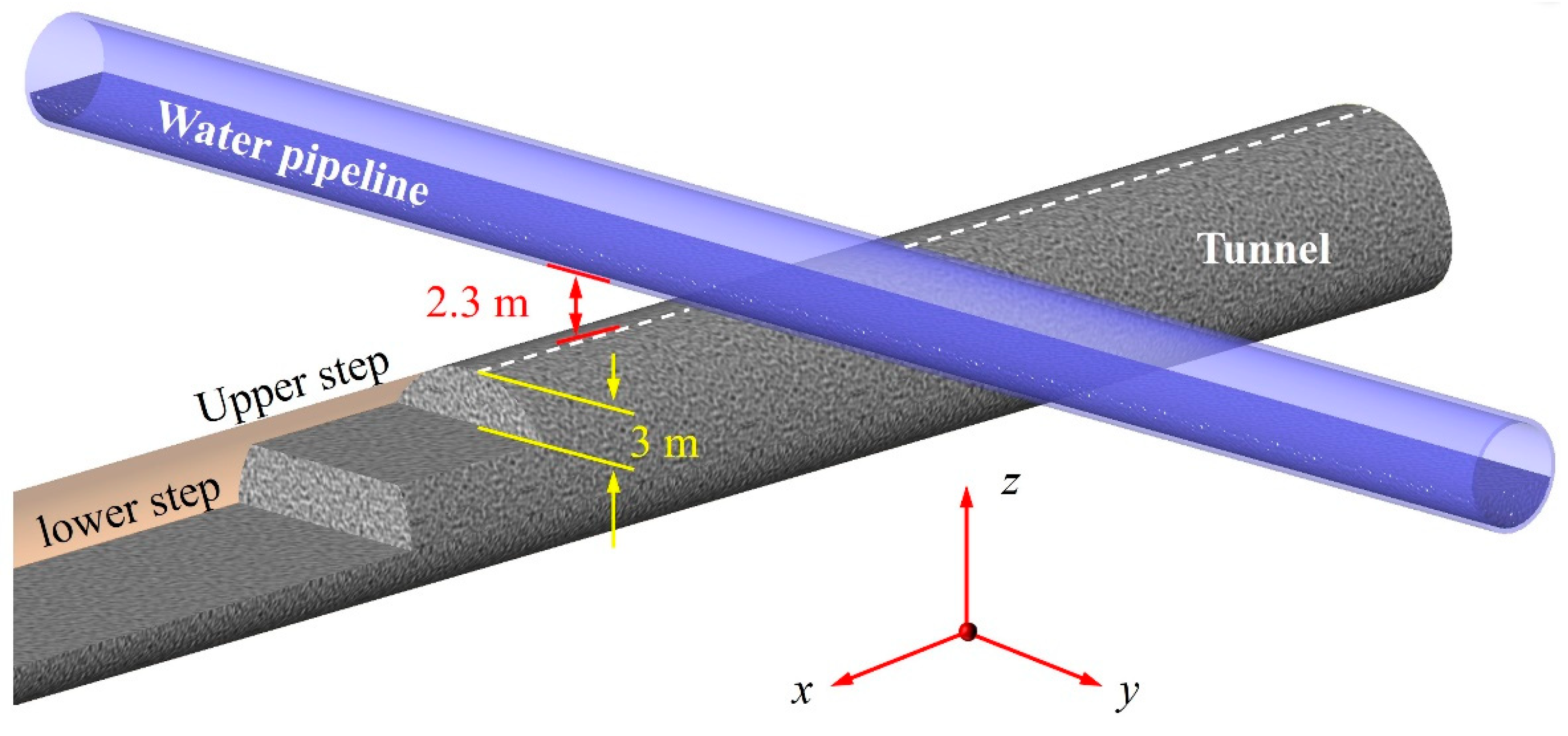
2. Engineering Information
2.1. Project Overview
2.2. Parameters of Blasting Scheme
3. Blasting Test and Vibration Safety Evaluation
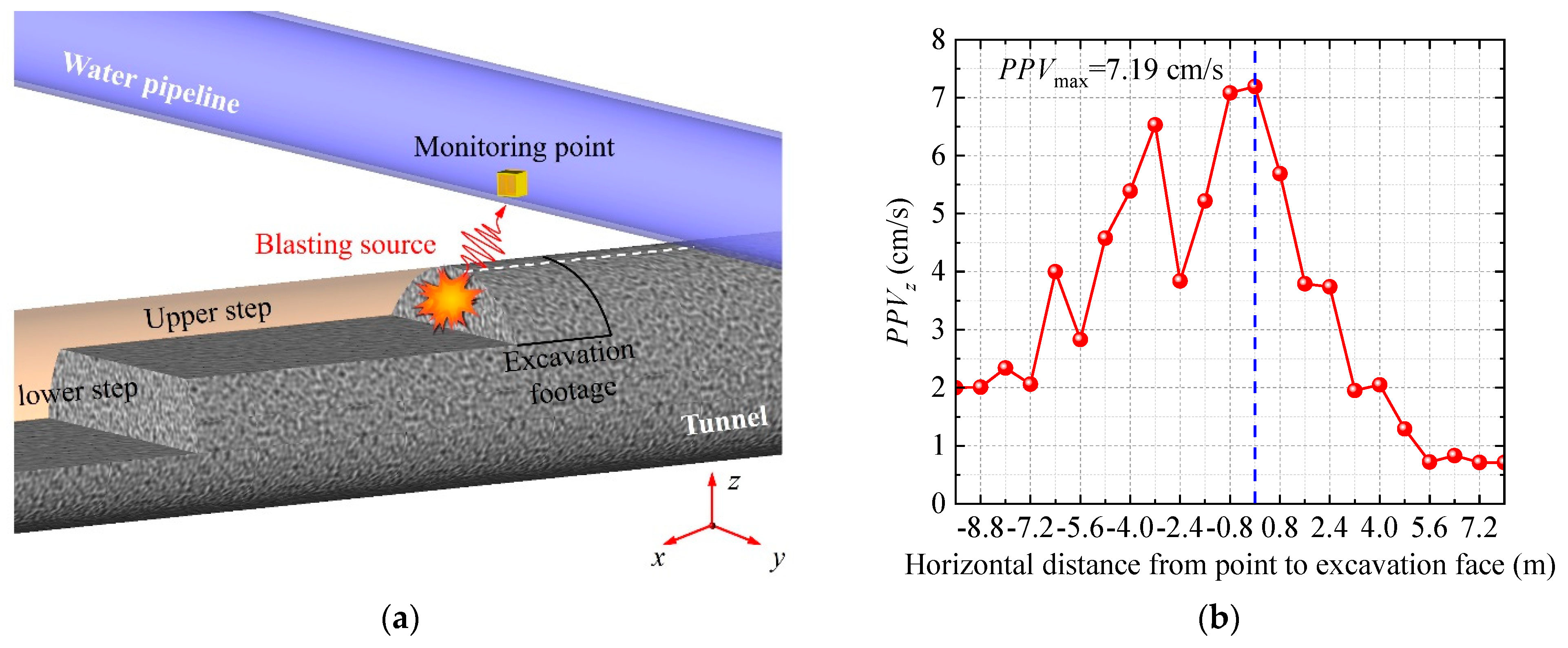
3.1. Determination of the Blast Hole Type for Greatest Influence on Pipeline
3.2. Blasting Test and Vibration Safety Evaluation of Water Pipeline
4. Cumulative Damage Theory and Numerical Model Establishment
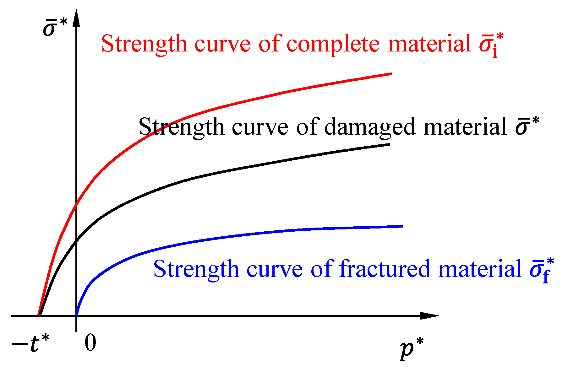
4.1. Surrounding Rock Model
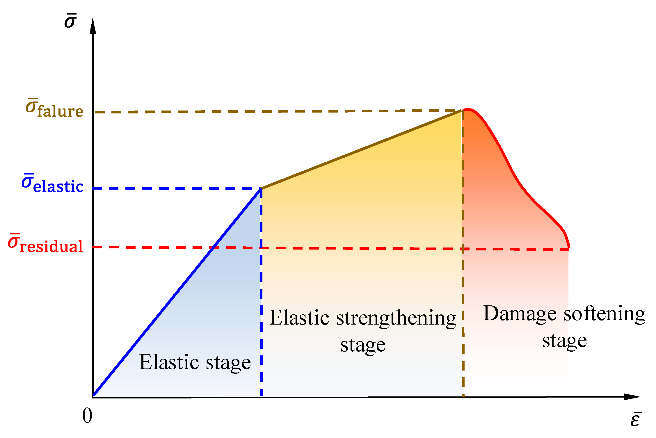
4.2. Concrete Model of the Pipeline
4.3. Reinforcement Skeleton Material Model and Parameters
4.4. Explosion Stress Wave Loading Theory and Simulation Method
4.5. Calculation Model Design and Verification
4.6. Vibration Response of Original Non-Electric Detonator Blasting
- (1)
- The y-direction is the vertical direction of the model, while the x- and z-directions are the horizontal directions. The vibration response in the vertical direction (with a PPV of 79.12 cm/s) was significantly higher than that in the horizontal directions (with PPVs of 28.31 cm/s and 29.98 cm/s in the x and z directions, respectively). This is mainly because the blasting seismic wave generated by the tunnel blasting propagates upward and reaches the bottom of the pipeline, causing intensive vibration of the pipeline;
- (2)
- From the results of the integration PPV (Figure 11d), the integration PPV of H1, H2, and H4 detonators is higher than that of H3 and H5 after detonation. At this point, the distance between the pipeline and the source of the explosion is sufficiently small, and the impact of the distance factor on the outcome far outweighs the influence of other factors. Hence, the PPV result (69.03 cm/s) caused by the blasting of peripheral holes (H4) is slightly higher than that (65.49 cm/s) caused by the blasting of cutting holes (H1);
- (3)
- According to the requirements of the current national standard [20] for hydraulic tunnels and other similar structures, a PPV exceeding 15 cm/s will cause damage to the structure. The maximum PPV, 79.12 cm/s, has significantly exceeded the allowable vibration velocity. Blasting using non-electric detonators will cause serious damage to the pipeline;
- (4)
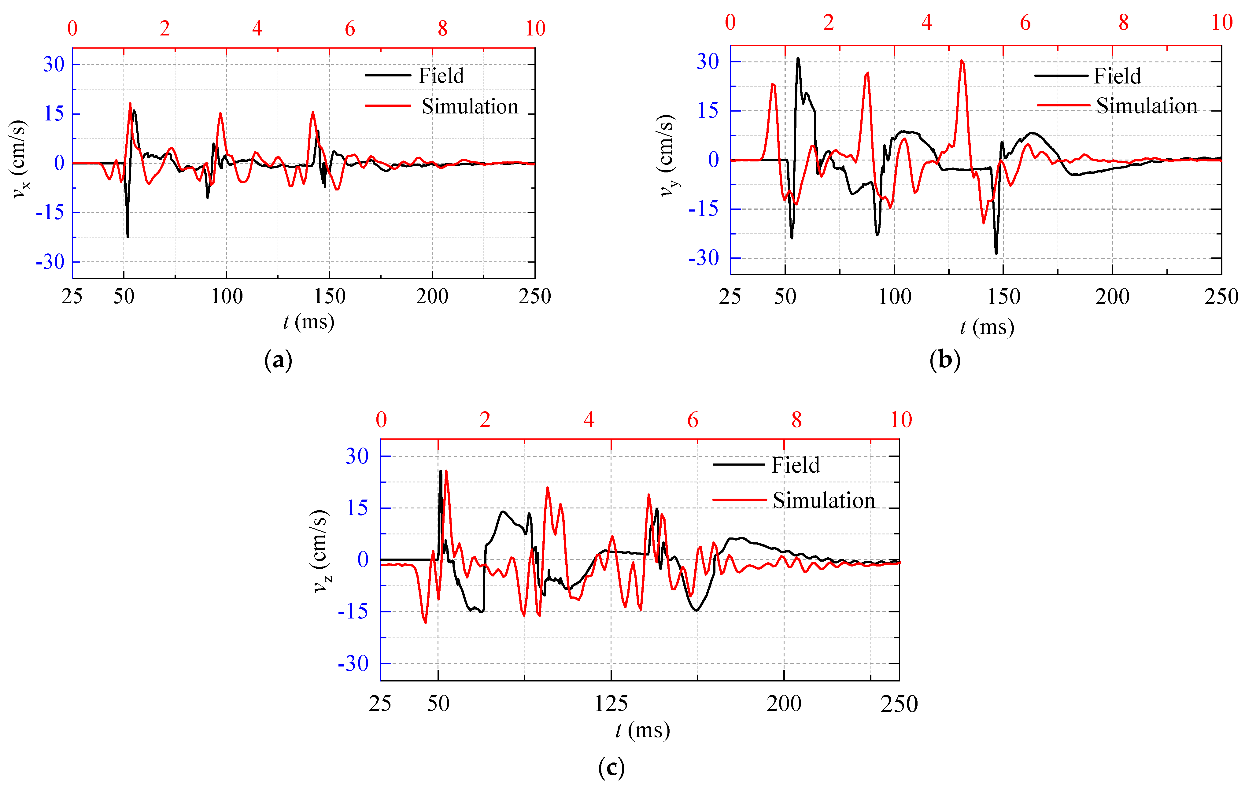
- The vibration waveforms generated by the five-part detonations (H1–H5) based on the set delay time were relatively independent, and the adjacent vibration waves were not superimposed. This indicates that the delay time setting of the blast holes in the numerical simulation is reasonable and can better reflect the actual situation on-site during blasting on construction.
5. Blasting Vibration Reduction Effect Analysis Using Electronic Detonators
5.1. The Improvement Scheme for Blasting Using Electronic Detonator
- (1)
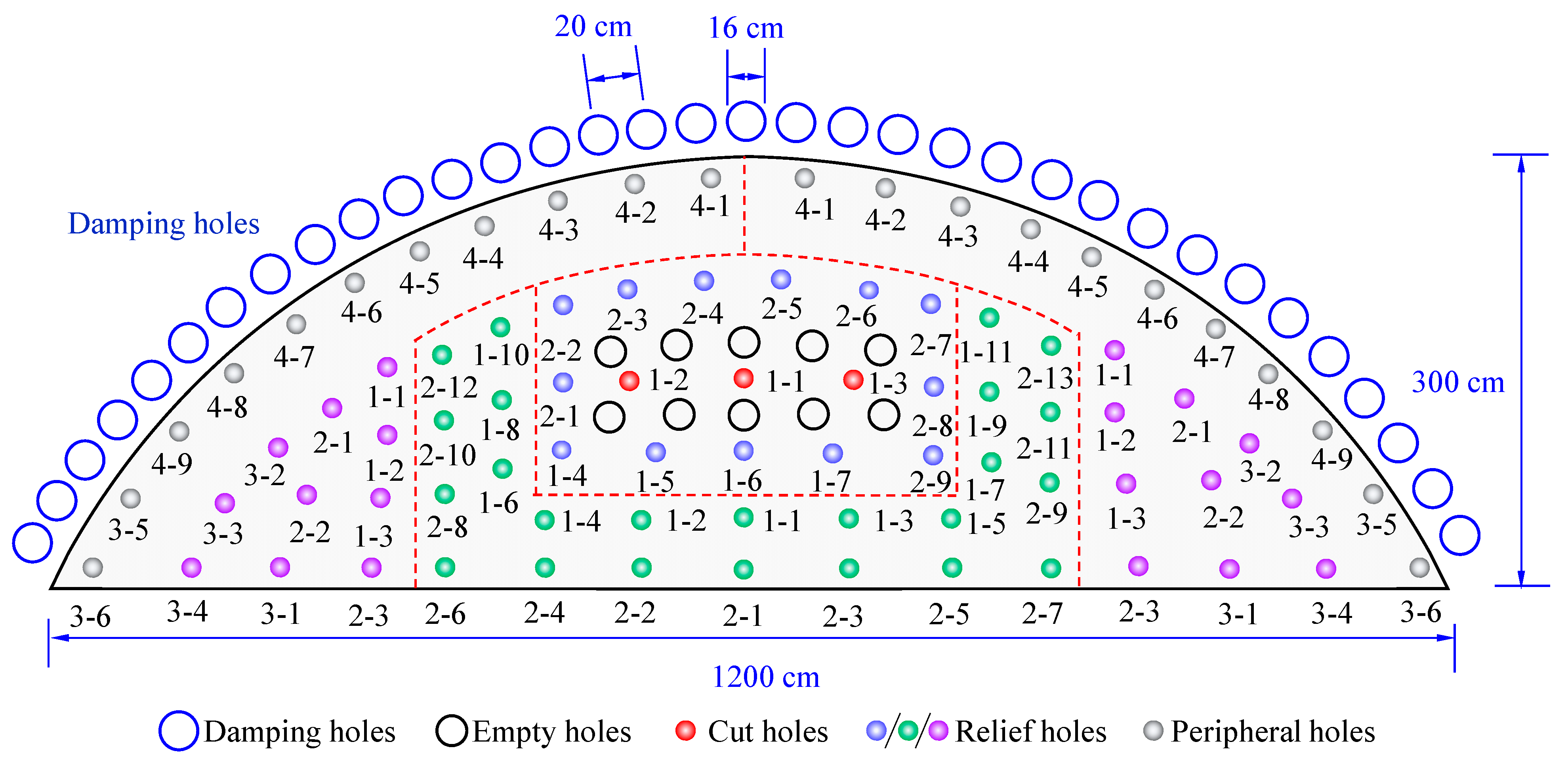
- Hole-by-hole blasting technology using electronic detonators was applied to replace the multi-hole simultaneous initiation technology using a non-electric detonator. The charge weights of the blast holes were reduced by increasing the number of blast holes and reducing their spacing and excavation footage. After optimization, the depth of the blast hole was 0.6 m, and the single-hole charge was 0.3 kg except for 0.2 kg in the peripheral hole. The total weight was 21.5 kg. The optimization design of blasting construction was achieved by using electronic detonators with a precise delay of 10 ms that can be implemented in a single hole;
- (2)
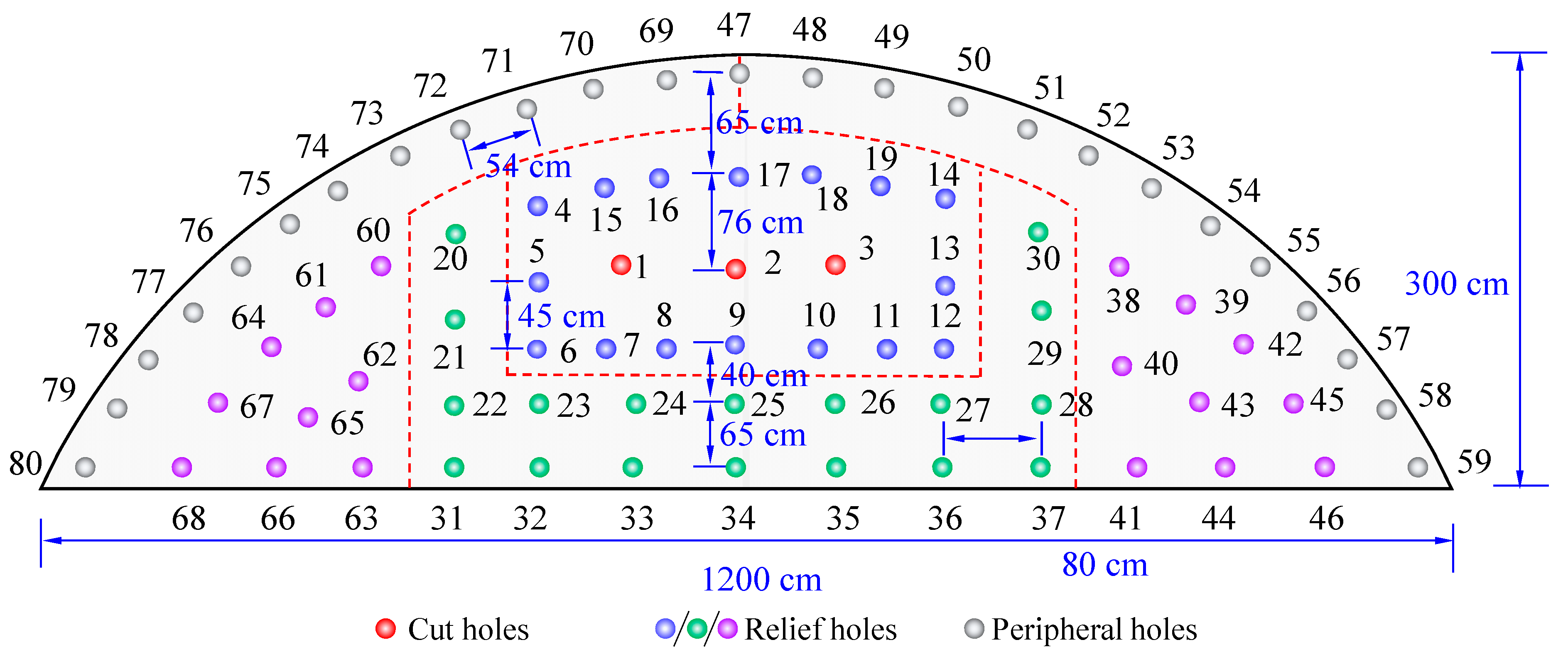
- In order to make the blast area where detonation first as the free face for subsequent detonation, the upper bench is divided into four blasting zones that expand from the center to the surrounding areas. The four partitions of the blast holes are evenly distributed. Cut holes 1–19 were blasting partition I. Blast holes 20–37 were blasting partition II. Blast holes 38–59 were blasting partition III. Blast holes 60–80 were blasting partition IV. To reduce the squeezing effect of rocks on the blast holes, a certain number of empty holes are evenly distributed around the cut holes. The positions and numbers of the blast holes are shown in Figure 12. Layout of blast holes using electronic detonators.
5.2. Comparison of Vibration Response between Non-Electric and Electronic Detonators
5.2.1. Comparison of Vibration Response of the Dangerous Points on the Pipeline
- (1)
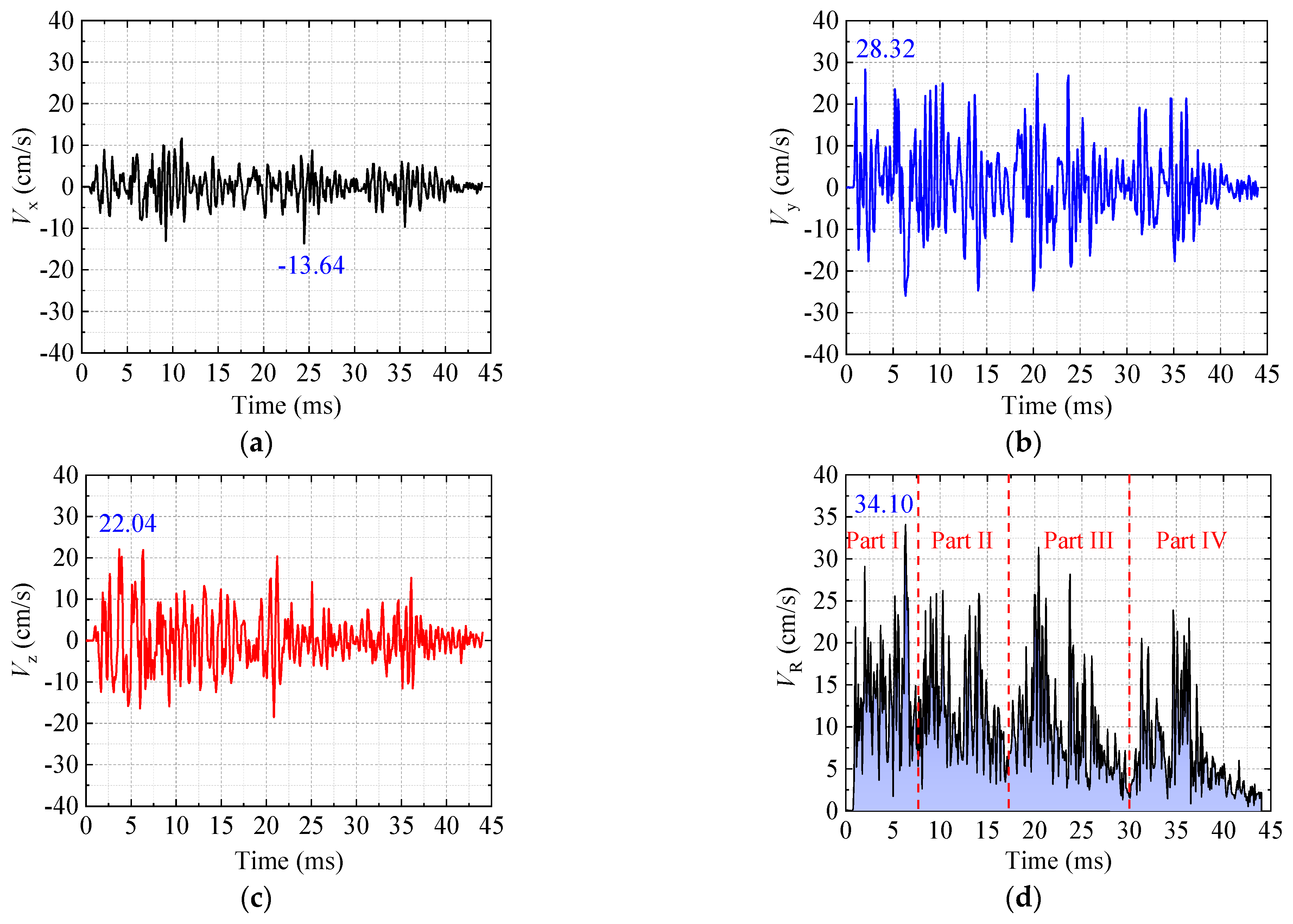
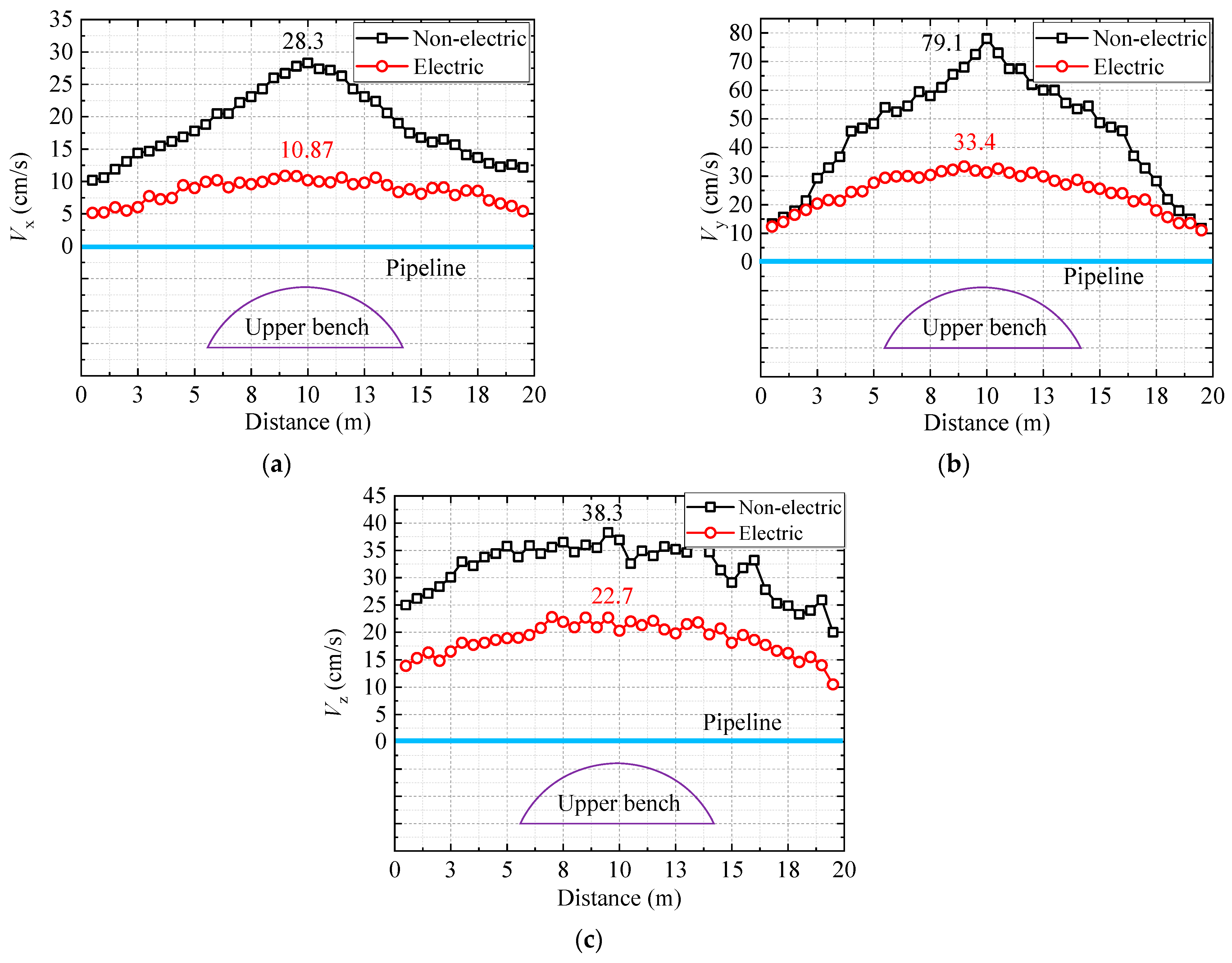
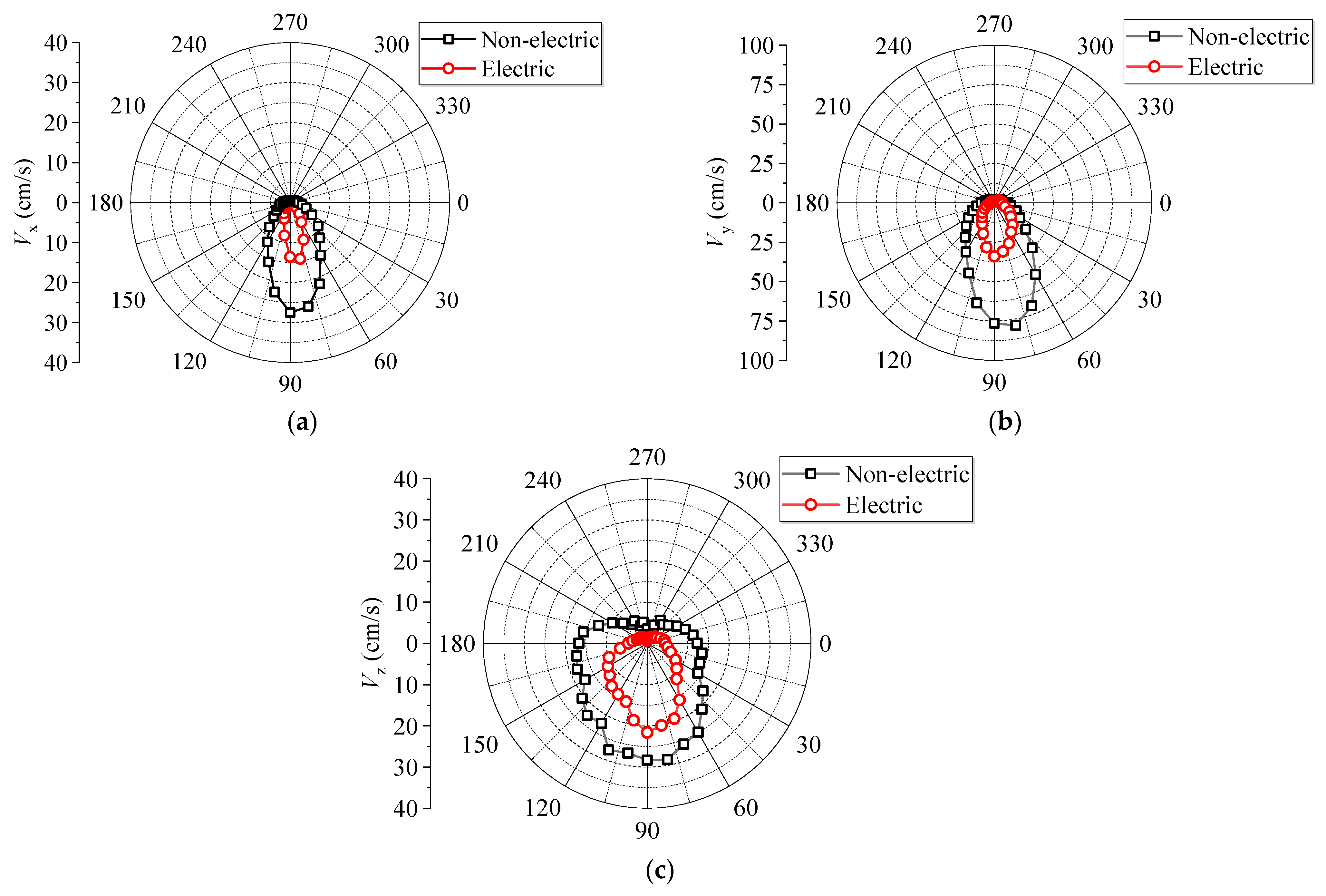
- The vibration velocity in the vertical direction exceeds that in the horizontal direction. The PPV in the vertical direction and horizontal direction are 28.32 cm/s and 22.04 cm/s, respectively. After using the hole-by-hole detonation technology of electronic detonators, the maximum PPV is reduced from 79.12 cm/s to 28.32 cm/s. The vibration velocity is significantly reduced by 64.21%;
- (2)
- From the results of the integration PPV (Figure 13d), the integration PPV of Partitions I and III was significantly higher than those of Partitions II and IV after detonation. It is again proven that in the near range of blasting, the pipeline is significantly affected by the blast vibrations induced by the holes close to it. However, although the blast holes of Partitions III and IV were symmetrically distributed, the vibration velocity of Partition IV was lower than that of Partition III. The mainly because, after Partition III was blasted, more free surfaces were created for the blasting of Partition IV, which effectively reduced the vibration response;
- (3)
- According to the safety standard [20], the maximum PPV under electronic detonator blasting is 28.32 cm/s, which exceeds the safe allowable vibration velocity. Further vibration reduction measures should be implemented to ensure that the PPV meets the safety requirements;
- (4)
- The vibration velocity waveform caused by the hole-by-hole blasting using electronic detonators fluctuates relatively gently. However, the vibration velocity produced by the simultaneous blasting of multiple holes using a non-electric detonator fluctuates in a pulse-type manner.
5.2.2. Comparison of Pipeline Axial PPV under Two Detonation Methods
5.2.3. The PPV on the Pipeline Profile under Two Detonation Methods
5.3. Comparison of the Cumulative Damage to the Pipeline in the Two Blasting Schemes
- (1)
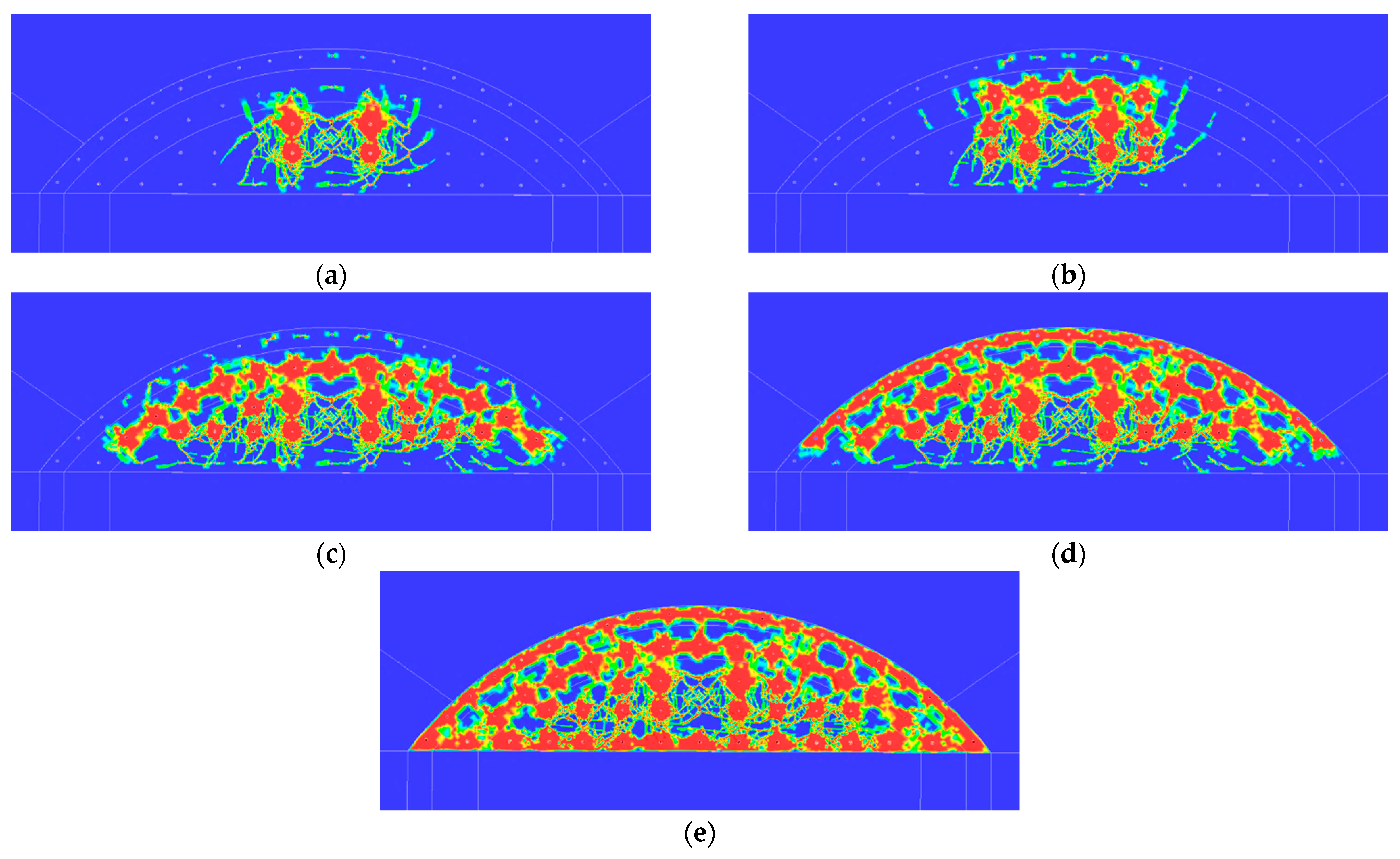
- Owing to the simultaneous initiation of cut holes using non-electric detonators, damage with a width of 1.5 m was generated on the pipeline. However, for cut-hole blasting with a small amount of charge using hole-by-hole initiation technology, the damage to the pipeline owing to blasting with electronic detonators is small;
- (2)
- With an increase in the number of blast hole ignitions, the range of influence of the seismic wave generated by blast hole blasting gradually increases; hence, the range of damage to the pipeline, induced by the non-electric and the electronic detonator blasting, gradually expands from the center of the nearest dangerous point to the sides. When the relief holes H2 are blasted, the damage range under non-electric and electronic detonator blasting increases by 3.0 m and 2.2 m, respectively. This is mainly because the relief holes above the cutting holes were much closer to the pipeline, and the number of blast holes detonated, and the number of explosives increased significantly, resulting in a greater increase in the cumulative damage to the pipeline;
- (3)
- Because some of the peripheral holes were close to the pipeline, and the influence range of the blasting seismic wave generated by peripheral hole blasting was larger than that of the other holes, the cumulative damage to the pipeline increased significantly with the initiation of peripheral holes. The cumulative damage range caused by the non-electric and electronic detonator blasting increased by 9.5 m and 4.7 m, respectively;
- (4)
- The increase in the damage variable D is consistent with the increase in the blasting damage range under the action of different blast hole blasting. When the relief holes above the cutting hole exploded, the damage variable D increased rapidly. The damage variable D of non-electric and electronic detonators increased by 0.18 and 0.12, respectively. In both explosion scenarios, the outermost peripheral holes are closest to the pipeline, and their explosive impacts significantly increase the damage variable D. Therefore, the above results also prove that when the pipeline is in the close range of tunnel blasting, the influence of the explosive impact of relief and peripheral holes is larger than that of the cutting holes.
6. Pipeline Safety Evaluation and Vibration Reduction Solutions
6.1. Safety Evaluation of Pipeline under Blasting Vibration
6.2. Vibration Reduction Technology Using Empty Holes and Barrier Holes
- (1)
- The cutting hole that is detonated first will be subjected to significant surrounding rock confinement, so it is necessary to have a vibration-reduction design for it. Placing large-diameter empty holes around the cutting hole can significantly reduce the adverse effects of surrounding rock. In this project application, ten empty holes with a diameter of 10 cm and a depth of 20 m were designed to surround the cutting holes;
- (2)
- To further reduce vibrations, a series of large pipe roofs were designed on the upper portion of the tunnel excavation profile. It can not only enhance the supporting effect in the middle interbedded rock layer but also has a good effect in blocking explosive impact [53]. In this application case, widely used on-site pipe roofs with a diameter of 159 mm and a length of 40 m have been used. Translation: Their spacing was designed to be relatively dense at 20 cm.
7. Conclusions
- (1)
- Because the pipeline was located in the near range of the blasting source, it was mainly affected by the impact of the explosion of the closest holes. Through precise substitutability in-situ testing, it was found that the PPV generated by the current blasting plan would exceed the safety standard, reaching almost 30 cm/s;
- (2)
- Due to the spatial relationship between the pipeline and the tunnel, the vertical vibration response caused by the explosion was significantly greater than that in other directions. The maximum PPV in the vertical direction using non-electric and electronic detonators was 79.12 cm/s and 28.32 cm/s, respectively. The vibration velocity was significantly reduced by 64.21% using the hole-by-hole initiation of the electronic detonators;
- (3)
- The location of the maximum PPV on the pipeline is at the bottom of the cross-section closest to the source of the explosion. Because of the large-diameter pipeline and its hollow characteristics, the PPV at the blasting side was much larger than that at the opposite side. The PPV decreased gradually as the distance along the axial extension of the pipeline from the blasting center increased, and the PPV of the electronic detonators decayed more slowly than that of the non-electric detonators. Because the maximum displacement of the pipeline was only 0.4 mm, the displacement standard was not suitable for evaluating the vibration safety of pipelines subjected to tunnel blasting;
- (4)
- The cumulative damage caused by the blasting of electronic detonators was less than that caused by non-electric detonators. After the nearest peripheral holes away from the pipeline detonated, the cumulative damage variable D and damage range increased rapidly, for non-electric and electronic detonator blasting increasing by 9.5 m and 4.7 m, respectively. The use of electronic detonator design can reduce the cumulative damage range by about 50.5%. The PPV, dynamic tensile strength, and cumulative damage variables were used to evaluate the safety of the pipelines. Division blasting, hole-by-hole initiation of electronic detonators, empty holes, and large pipe roofs were adopted to reduce the blasting vibration to meet safety requirements.
Author Contributions
Funding
Institutional Review Board Statement
Informed Consent Statement
Data Availability Statement
Conflicts of Interest
References
- Kouretzis, G.P.; Bouckovalas, G.D.; Gantes, C.J. Analytical calculation of blast-induced strains to buried pipelines. Int. J. Impact Eng. 2007, 34, 1683–1704. [Google Scholar] [CrossRef]
- Abedi, A.S.; Hataf, N.; Ghahramani, A. Analytical solution of the dynamic response of buried pipelines under blast wave. Int. J. Rock Mech. Min. Sci. 2016, 88, 301–306. [Google Scholar] [CrossRef]
- Xia, Y.Q.; Jiang, N.; Zhou, C.B.; Meng, X.Z.; Luo, X.D.; Wu, T.Y. Theoretical solution of the vibration response of the buried flexible HDPE pipe under impact load induced by rock blasting. Soil Dyn. Earthq. Eng. 2021, 146, 106743. [Google Scholar] [CrossRef]
- Yan, S.; Xu, Y.R.; Chang, H.Y. Numerical simulation of dynamic response of buried pipeline by ground explosion. Earth Space 2012, 1159–1166. [Google Scholar]
- Parviz, M.; Aminnejad, B.; Fiouz, A. Numerical Simulation of Dynamic Response of Water in Buried Pipeline under Explosion. KSCE J. Civ. Eng. 2017, 21, 2798–2806. [Google Scholar] [CrossRef]
- Zhao, K.; Jiang, N.; Jia, Y.S.; Yao, Y.K.; Zhu, B.; Zhou, C.B. Dynamic failure mechanism of gas pipeline with flange joint under blasting seismic wave. Explos. Shock. Waves 2021, 41, 100–115. [Google Scholar]
- Zhu, B.; Jiang, N.; Zhou, C.B.; Jia, Y.S.; Luo, X.D.; Wu, T.Y. Blasting seismic effect of buried cast iron pipeline in silty clay layer. J. Zhejiang Univ. 2021, 55, 500–510. [Google Scholar]
- Zhao, K.; Jiang, N.; Zhou, C.B.; Li, H.B.; Cai, Z.W.; Zhu, B. Dynamic behavior and failure of buried gas pipeline considering the pipe connection form subjected to blasting seismic waves. Thin-Walled Struct. 2022, 170, 108495. [Google Scholar] [CrossRef]
- Cao, H.Z.; Jiang, N.; Zhou, C.B.; Li, H.B.; Cai, Z.W.; Huang, Y.W. Dynamic response and safety assessment of inner-wall corroded concrete pipeline in service subjected to blasting vibration. Struct. Concr. 2023, 24, 451–467. [Google Scholar] [CrossRef]
- Wu, T.Y.; Jiang, N.; Zhou, C.B.; Luo, X.D.; Li, H.B.; Zhang, Y.Q. Experimental and numerical investigations on damage assessment of high-density polyethylene pipe subjected to blast loads. Eng. Fail. Anal. 2022, 131, 105856. [Google Scholar] [CrossRef]
- Guan, X.M.; Zhang, L.; Wang, Y.W.; Fu, H.X.; An, J.Y. Velocity and Stress Response and Damage Mechanism of Three Types Pipelines Subjected to Highway Tunnel Blasting Vibration. Eng. Fail. Anal. 2020, 118, 104840. [Google Scholar] [CrossRef]
- Qin, T.G.; Wu, M.Z.; Jia, L.; Xie, L.L.; Wu, L. Effects of Vibration on Adjacent Pipelines under Blasting Excavation. Appl. Sci. 2023, 13, 121. [Google Scholar] [CrossRef]
- Francini, R.B.; Baltz, W.N. Blasting and Construction Vibrations Near Existing Pipelines: What Are Appropriate Levels. In Proceedings of the International Pipeline Conference, Calgary, AB, Canada, 29 September–3 October 2008; Volume 48586, pp. 519–531. [Google Scholar]
- De, A.; Morgante, A.N.; Zimmie, T.F. Numerical and Physical Modeling of Geofoam Barriers as Protection against Effects of Surface Blast on Underground Tunnels. Geotext. Geomembr. 2016, 44, 1–12. [Google Scholar] [CrossRef]
- Mane, A.S.; Shete, S.; Bhuse, A. Effect of Geofoam Inclusion on Deformation Behavior of Buried Pipelines in Cohesive Soils. In Proceedings of the International Congress and Exhibition “Sustainable Civil Infrastructures: Innovative Infrastructure Geotechnology”, Moscow, Russia, 4 September 2017; pp. 20–33. [Google Scholar]
- Jiang, N.; Jia, Y.S.; Yao, Y.K.; Sun, J.S.; Zhu, B.; Wu, T.Y. Experimental investigation on the influence of tunnel crossing blast vibration on upper gas pipeline. Eng. Fail. Anal. 2021, 127, 105490. [Google Scholar] [CrossRef]
- Patnailk, G.; Rajput, A. Safety assessment of underground steel pipelines with CFRP protection against subsurface blast loading. Structures 2023, 54, 1541–1559. [Google Scholar] [CrossRef]
- Mahgoub, A.; Naggar, H.E. Seismic Design of Metal Arch Culverts: Design Codes vs. Full Dynamic Analysis. J. Earthqu. Eng. 2019, 25, 2231–2268. [Google Scholar] [CrossRef]
- Davis, C.A.; Bardet, J.P. Responses of Buried Corrugated Metal Pipes to Earthquakes. J. Geotech. Geoenviron. Eng. 2000, 126, 28–39. [Google Scholar] [CrossRef]
- GB6722-2014; Safety Regulations for Blasting. State Standardization Publishing House: New South Wales, Australia, 2016. (In Chinese)
- Jiang, N.; Zhou, C.B. Blasting vibration safety criterion for a tunnel liner structure. Tunn. Undergr. Space Technol. 2012, 32, 52–57. [Google Scholar] [CrossRef]
- Zhang, Z.; Zhou, C.B.; Remennikov, A.; Wu, T.Y.; Lu, S.W.; Xia, Y.Q. Dynamic response and safety control of civil air defense tunnel under excavation blasting of subway tunnel. Tunn. Undergr. Space Technol. 2021, 112, 103879. [Google Scholar] [CrossRef]
- Cui, Y.; Gao, Y.H.; Fang, J.; Qu, Z.; Li, Z.J.; Zhao, M.T. Research on damage assessment of buried pipelines with circular dent defects subjected to blast loading. Eng. Fail. Anal. 2024, 163, 108581. [Google Scholar] [CrossRef]
- Li, P.F.; Chen, Y.; Huang, J.L.; Wang, X.Y.; Liu, J.Y.; Wu, J. Design principles of prestressed anchors for tunnels considering bearing arch effect. Comput. Geotech. 2024, 163, 108473. [Google Scholar] [CrossRef]
- Zhu, B.; Jiang, N.; Zhou, C.B.; Luo, X.D.; Li, H.B.; Chang, X.; Xia, Y.Q. Dynamic interaction of the pipe-soil subject to underground blasting excavation vibration in an urban soil-rock stratum. Tunn. Undergr. Space Technol. 2022, 129, 104700. [Google Scholar] [CrossRef]
- Zhang, Y.Q.; Jiang, N.; Yao, Y.K.; Zhou, C.B.; Meng, X.Z.; Zhang, Z. Structural safety and failure analysis of buried jointed high-density polyethylene corrugated pipelines subjected to blast vibration. Eng. Fail. Anal. 2024, 163, 108473. [Google Scholar] [CrossRef]
- Chen, Y.; Li, P.F.; Miao, C.; Yang, L.; Cui, X.P.; Wang, S. Failure Behaviors of Anchored Rock Mass with Various Fracture Inclinations in Tunnels. Arab. J. Sci. Eng. 2024, 1–23. [Google Scholar] [CrossRef]
- Li, S.L.; Ling, T.L.; Liu, D.S.; Liang, S.F.; Zhang, R.; Huang, B.; Liu, K. Determination of Rock Mass Parameters for the RHT Model Based on the Hoek–Brown Criterion. Rock Mech. Rock Eng. 2023, 56, 2861–2877. [Google Scholar] [CrossRef]
- Li, H.B.; Xia, X.; Li, J.C.; Zhao, J.; Liu, B.; Liu, Y.Q. Rock damage control in bedrock blasting excavation for a nuclear power plant. Int. J. Rock Mech. Min. Sci. 2011, 48, 210–218. [Google Scholar]
- Yang, J.H.; Yao, C.; Jiang, Q.H.; Lu, W.B.; Jiang, S.H. 2D numerical analysis of rock damage induced by dynamic in-situ stress redistribution and blast loading in underground blasting excavation. Tunn. Undergr. Space Technol. 2017, 70, 221–232. [Google Scholar] [CrossRef]
- Yang, J.H.; Lu, W.B.; Hu, Y.G.; Chen, M. Numerical Simulation of Rock Mass Damage Evolution during Deep-Buried Tunnel Excavation by Drill and Blast. Rock Mech. Rock Eng. 2015, 48, 2045–2059. [Google Scholar] [CrossRef]
- Ling, T.L.; Li, S.L.; Lu, D.S.; Liang, S.F. Blasting Damage of Tunnel Rock Mass Based on Cumulative Effect. Rock Mech. Rock Eng. 2023, 56, 1679–1695. [Google Scholar] [CrossRef]
- Gao, Y.P.; Fu, H.X.; Ji, X.C.; Rong, X.; Ye, Z.C.; Meng, Z.W. Research and application of interlaid rock vibration law in drilling and blasting construction of small clear distance tunnel. Chin. J. Rock Mech. Eng. 2020, 39, 3440–3449. (In Chinese) [Google Scholar] [CrossRef]
- Guan, X.M.; Yang, N.; Zhang, W.J.; Li, M.; Liu, Z.; Wang, X.; Zhang, S. Vibration response and failure modes analysis of the temporary support structure under blasting excavation of tunnels. Eng. Fail. Anal. 2022, 136, 106188. [Google Scholar] [CrossRef]
- Li, Y.Z. Calibration of Constitutive Parameters of Granite JH-2 and Numerical Simulation of Damage Characteristics under Repeated Loads; Hefei University of Technology: Hefei, China, 2020. [Google Scholar]
- Xia, Y.Q.; Jiang, N.; Zhou, C.B.; Sun, J.S. Dynamic Response Characteristics of Water Supply Pipeline under Blasting Vibration of Underneath Tunnel. Blasting 2019, 36, 6–13+37. [Google Scholar]
- Herrmann, W. Constitutive equation for the dynamic compaction of ductile porous materials. J. Appl. Phys. 1969, 40, 2490–2499. [Google Scholar] [CrossRef]
- Nie, Z.Y. Experimental Study on RHT Model Parameters of Three Typical Rock Materials. Master’s Thesis, National University of Defense Technology, Changsha, China, 2021. [Google Scholar]
- Guan, X.M.; Zhang, L.; Wang, L.M.; Fu, H.X.; Yu, D.M.; Chen, G.; Ding, Y.; Jiang, W.L. Blasting vibration characteristics and safety standard of pipeline passed down by tunnel in short distance. J. Cent. South Univ. 2019, 50, 2870–2885. [Google Scholar]
- Yilmaz, O.; Unlu, T. Three dimensional numerical rock damage analysis under blasting load. Tunn. Undergr. Space Technol. 2013, 38, 266–278. [Google Scholar] [CrossRef]
- Ling, T.L. Study on Blasting Damage and Cumulative Effect of Sorrounding Rock in Excavation of Great Wall Station. Ph.D. Thesis, China University of Mining and Technology-Beijing, Beijing, China, 2019. [Google Scholar]
- Lu, Y.; Jin, C.Y.; Wang, Q.; Han, T.; Zhang, J.; Chen, L. Numerical study on spatial distribution of blast-induced damage zone in open-pit slope. Int. J. Rock Mech. Min. Sci. 2023, 163, 105328. [Google Scholar] [CrossRef]
- Yang, J.H. Coupling Effect of Blasting and Transient Release of In-Situ Stress during Deep Rock Mass Excavation; Wuhan University: Wuhan, China, 2014. [Google Scholar]
- Gradyt, D.E.; Kipp, M.E. Continuum modelling of explosive fracture in oil shale. Int. J. Rock Mech. Min. Sci. 1980, 17, 147–157. [Google Scholar] [CrossRef]
- Zhang, Q.B.; Zhao, J. A review of dynamic experimental techniques and mechanical behaviour of rock materials. Rock Mech. Rock Eng. 2014, 47, 1411–1478. [Google Scholar] [CrossRef]
- Hwang, Y.K.; Bolander, J.E.; Lim, Y.M. Evaluation of dynamic tensile strength of concrete using lattice-based simulations of spalling tests. Int. J. Fract. 2020, 221, 191–209. [Google Scholar] [CrossRef]
- Lu, Y.B.; Li, Q.M. About the dynamic uniaxial tensile strength of concrete-like materials. Int. J. Impact Eng. 2011, 38, 171–180. [Google Scholar] [CrossRef]
- Xu, X.B.; Jin, Z.Q.; Yu, Y.; Li, N. Impact properties of Ultra High Performance Concrete (UHPC) cured by steam curing and standard curing. Case Stud. Constr. Mater. 2022, 17, e01321. [Google Scholar] [CrossRef]
- Rong, Y.; Ren, H.L.; Xu, X.Z. An improved damage-plasticity material model for concrete subjected to dynamic loading. Case Stud. Constr. Mater. 2023, 19, e02568. [Google Scholar] [CrossRef]
- Mishra, S.; Chakraborty, T. Determination of high-strain-rate stress–strain response of granite for blast analysis of tunnels. J. Eng. Mech. 2019, 145, 04019057. [Google Scholar] [CrossRef]
- Chen, X.D.; Ge, L.M.; Yuan, H.T.; Zhou, J. Effect of prestatic loading on dynamic tensile strength of concrete under high strain rates. J. Mater. Civ. Eng. 2016, 28, 06016018. [Google Scholar] [CrossRef]
- Liu, F.; Li, Q.M. Stain-rate effects on the dynamic compressive strength of concrete-like materials under multiple stress state. Explos. Shock. Waves 2022, 42, 125–140. [Google Scholar]
- Guan, X.M.; Yao, Y.K.; Yang, N.; Xu, H.W.; Xin, B.C.; Li, B.Y. Analysis of factors influencing vibration reduction and design optimization of damping holes in adjacent tunnel blasting. Case Stud. Constr. Mater. 2023, 19, e02448. [Google Scholar] [CrossRef]
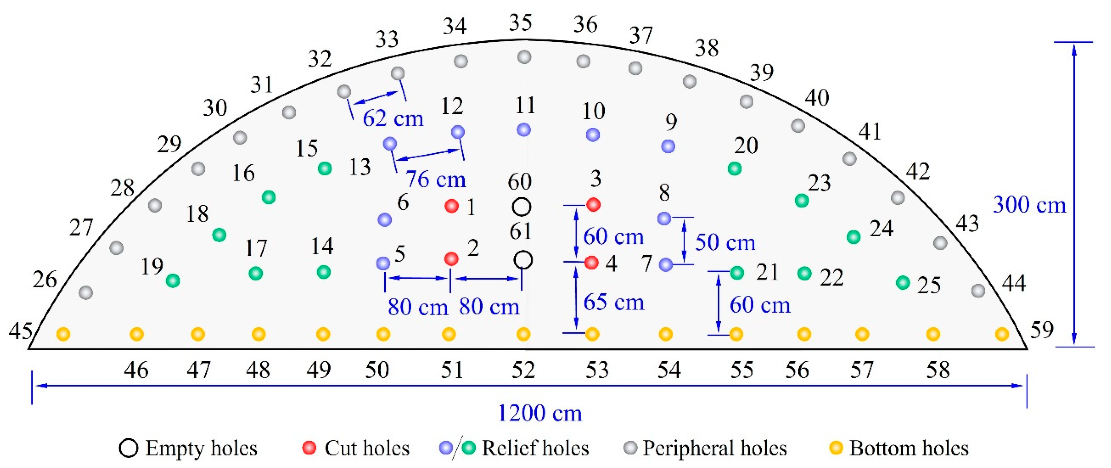








| Type of Hole | Part | Hole Number | Hole Quantity | Hole Depth (m) | Detonator Series | Single-Hole Charge (kg) | Explosive Charge (kg) |
|---|---|---|---|---|---|---|---|
| Cut holes | H1 | 1–4 | 4 | 2.5 | MS1 | 0.9 | 3.6 |
| Relief holes | H2 | 5–13 | 9 | 2.0 | MS3 | 0.7 | 6.3 |
| H3 | 14–25 | 12 | 2.0 | MS5 | 0.7 | 8.4 | |
| Peripheral holes | H4 | 26–44 | 19 | 2.0 | MS7 | 0.6 | 11.4 |
| Bottom holes | H5 | 45–59 | 15 | 2.0 | MS9 | 0.8 | 12.0 |
| Empty holes | H6 | 60, 61 | 2 | 2.5 |
| (kg/m3) | G (Gpa) | k1 (Gpa) | k2 (Gpa) | k3 (Gpa) | HEL (Gpa) | A | N | C |
|---|---|---|---|---|---|---|---|---|
| 2.46 × 10³ | 18.5 | 2.51 × 10² | 32.0 | −4.5 × 10³ | 3.0 × 10³ | 9.7 × 10⁻³ | 0.72 | 5.0 × 10⁻³ |
| B | M | (Gpa) | T/Gpa | D2 | β | D1 | Tf (Gpa) | Gf (J·m−2) |
| 0.32 | 0.72 | 25 | −5.3 × 10⁻² | 0.7 | 0.5 | 5.0 × 10⁻³ | 3.5 × 10⁻² | 70 |
(kg/m3) | A1 (Gpa) | A2 (Gpa) | A3 (Gpa) | B0 | B1 | A | G | pcrush (Gpa) | pcomp (Gpa) | fc (Gpa) | T1 | T2 |
|---|---|---|---|---|---|---|---|---|---|---|---|---|
| 2.41 × 10³ | 35.27 | 39.58 | 12.04 | 1.22 | 1.60 | 1.60 | 16.7 | 0.017 | 44.00 | 0.02 | 35.27 | 0.00 |
| βc | Βt | D2 | γ0 | ξ | B | D1 | Q0 | BQ | ||||
| 0.53 | 0.90 | 0.02 | 0.025 | 0.18 | 0.10 | 1.00 | 1.60 | 0.50 | 1.60 | 0.04 | 0.685 | 0.010 |
| Steel Type | (g/cm−3) | E (Gpa) | v | fy (Gpa) | Src (s−1) | Srp |
|---|---|---|---|---|---|---|
| Longitudinal bar | 7.85 | 206 | 0.3 | 335 | 40.5 | 5 |
| Stirrup | 7.85 | 206 | 0.3 | 235 | 40.5 | 5 |
| Type of Hole | Part | Hole Number | Line Charge Coefficient | Detonator Series | Equivalent Load Pressure (Mpa) |
|---|---|---|---|---|---|
| Cut holes | H1 | 1–4 | 0.70 | MS1 | 193.11 |
| Relief holes | H2 | 5–13 | 0.55 | MS3 | 151.74 |
| H3 | 14–25 | 0.55 | MS5 | 151.74 | |
| Peripheral holes | H4 | 26–44 | 0.40 | MS7 | 110.35 |
| Bottom holes | H5 | 45–59 | 0.60 | MS9 | 165.53 |
| Type of Hole | Hole Number | Partition | Hole Quantity | Delay Time Range (ms) |
|---|---|---|---|---|
| Cut holes | 1–3 | I | 3 | 0–20 |
| Relief holes | 4–14 | I | 11 | 70–170 |
| Relief holes | 15–19 | I | 5 | 230–270 |
| Relief holes | 20–30 | II | 11 | 0–100 |
| Relief holes | 31–37 | II | 7 | 150–220 |
| Relief holes | 38–46 | III | 9 | 0–80 |
| Peripheral holes | 47–59 | III | 13 | 130–250 |
| Relief holes | 60–68 | IV | 9 | 0–80 |
| Peripheral holes | 69–80 | IV | 12 | 130–240 |
Disclaimer/Publisher’s Note: The statements, opinions and data contained in all publications are solely those of the individual author(s) and contributor(s) and not of MDPI and/or the editor(s). MDPI and/or the editor(s) disclaim responsibility for any injury to people or property resulting from any ideas, methods, instructions or products referred to in the content. |
© 2024 by the authors. Licensee MDPI, Basel, Switzerland. This article is an open access article distributed under the terms and conditions of the Creative Commons Attribution (CC BY) license (https://creativecommons.org/licenses/by/4.0/).
Share and Cite
Guan, X.; Yang, N.; Yao, Y.; Xin, B.; Yu, Q. Evaluation of Cumulative Damage and Safety of Large-Diameter Pipelines under Ultra-Small Clear Distance Multiple Blasting Using Non-Electric and Electronic Detonators. Appl. Sci. 2024, 14, 9112. https://doi.org/10.3390/app14199112
Guan X, Yang N, Yao Y, Xin B, Yu Q. Evaluation of Cumulative Damage and Safety of Large-Diameter Pipelines under Ultra-Small Clear Distance Multiple Blasting Using Non-Electric and Electronic Detonators. Applied Sciences. 2024; 14(19):9112. https://doi.org/10.3390/app14199112
Chicago/Turabian StyleGuan, Xiaoming, Ning Yang, Yingkang Yao, Bocheng Xin, and Qingqing Yu. 2024. "Evaluation of Cumulative Damage and Safety of Large-Diameter Pipelines under Ultra-Small Clear Distance Multiple Blasting Using Non-Electric and Electronic Detonators" Applied Sciences 14, no. 19: 9112. https://doi.org/10.3390/app14199112
APA StyleGuan, X., Yang, N., Yao, Y., Xin, B., & Yu, Q. (2024). Evaluation of Cumulative Damage and Safety of Large-Diameter Pipelines under Ultra-Small Clear Distance Multiple Blasting Using Non-Electric and Electronic Detonators. Applied Sciences, 14(19), 9112. https://doi.org/10.3390/app14199112


