
Assessment of the Functional Properties of the Surfaces of Ductile Cast Iron Parts

 , , , ,
  and
and 
Abstract
1. Introduction
2. Materials and Methods
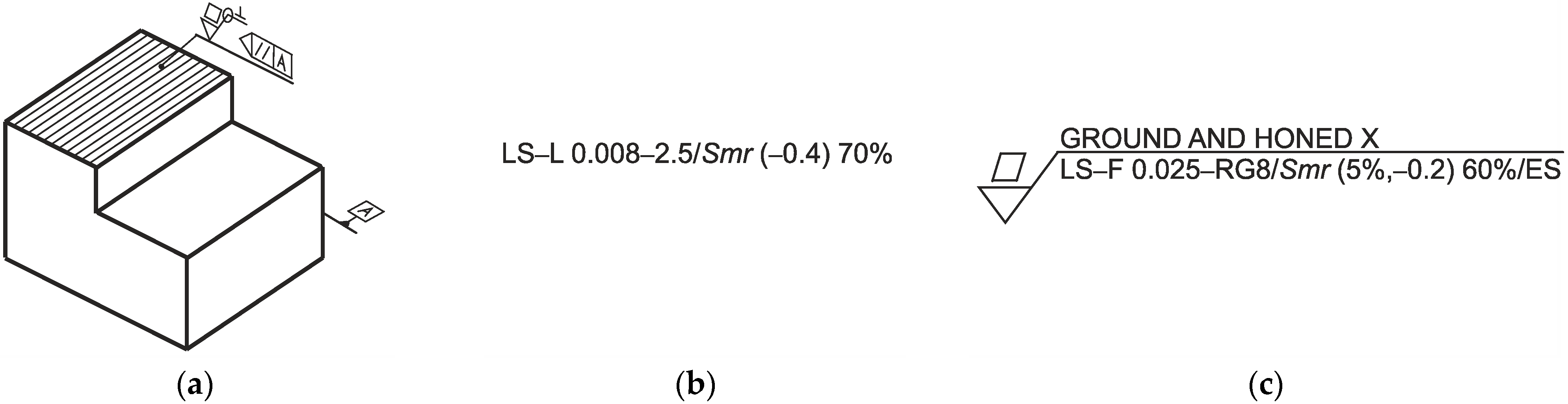
2.1. Evaluation of the Machinability of Cast Iron by the Geometric Texture State of the Surface
2.2. Studies on the Influence of Technological Machining Parameters on the Formation of Functional Properties of the Geometrical Texture of the Surface
3. Results
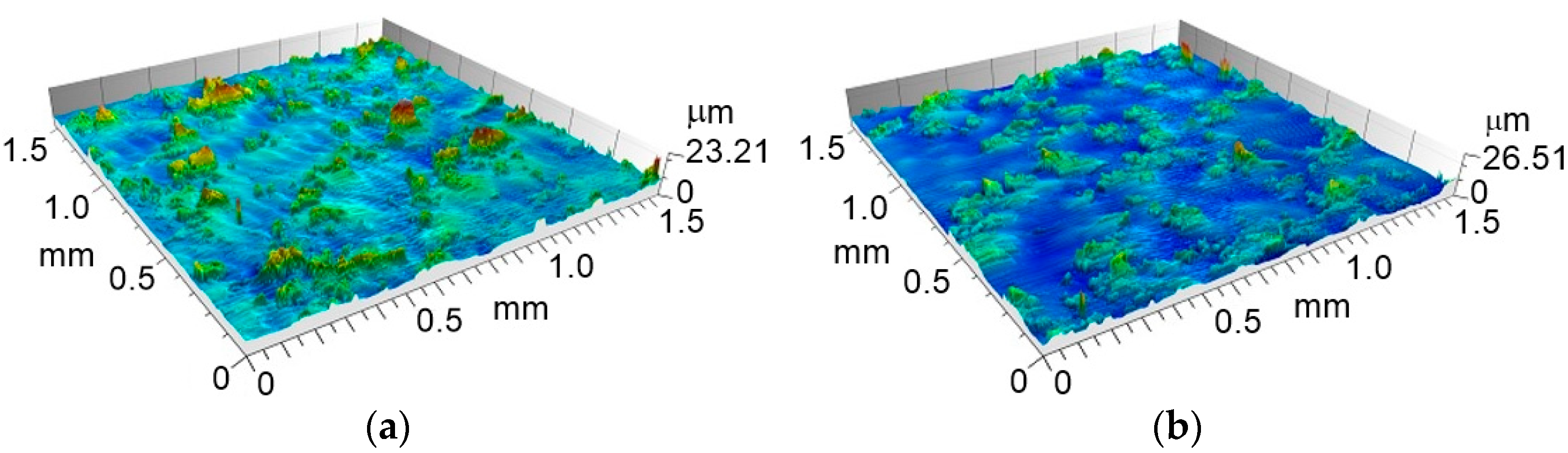
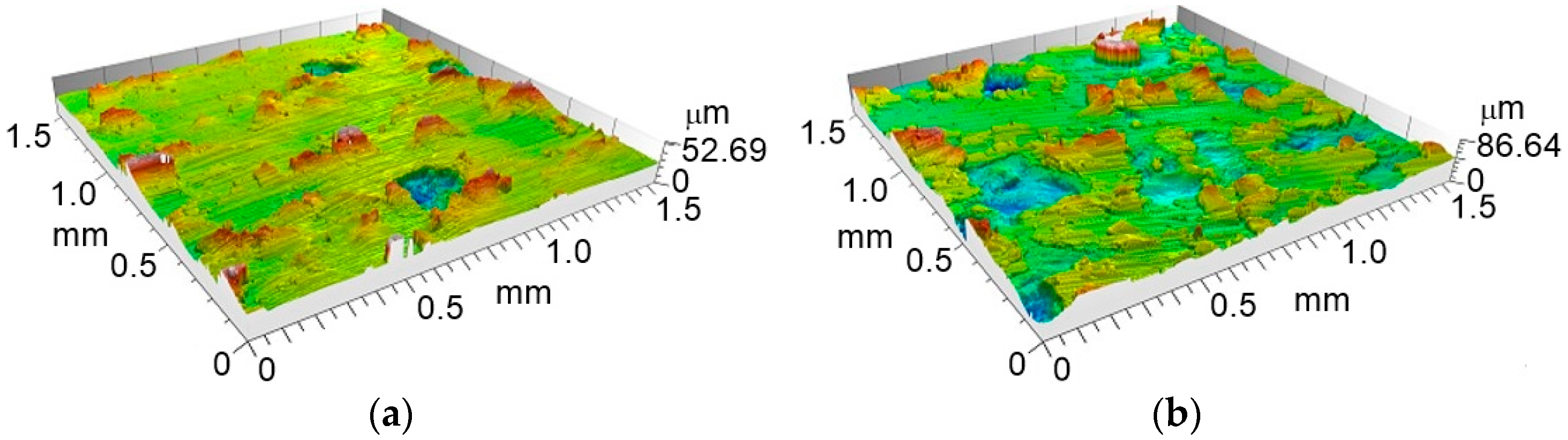
3.1. Surface Maps
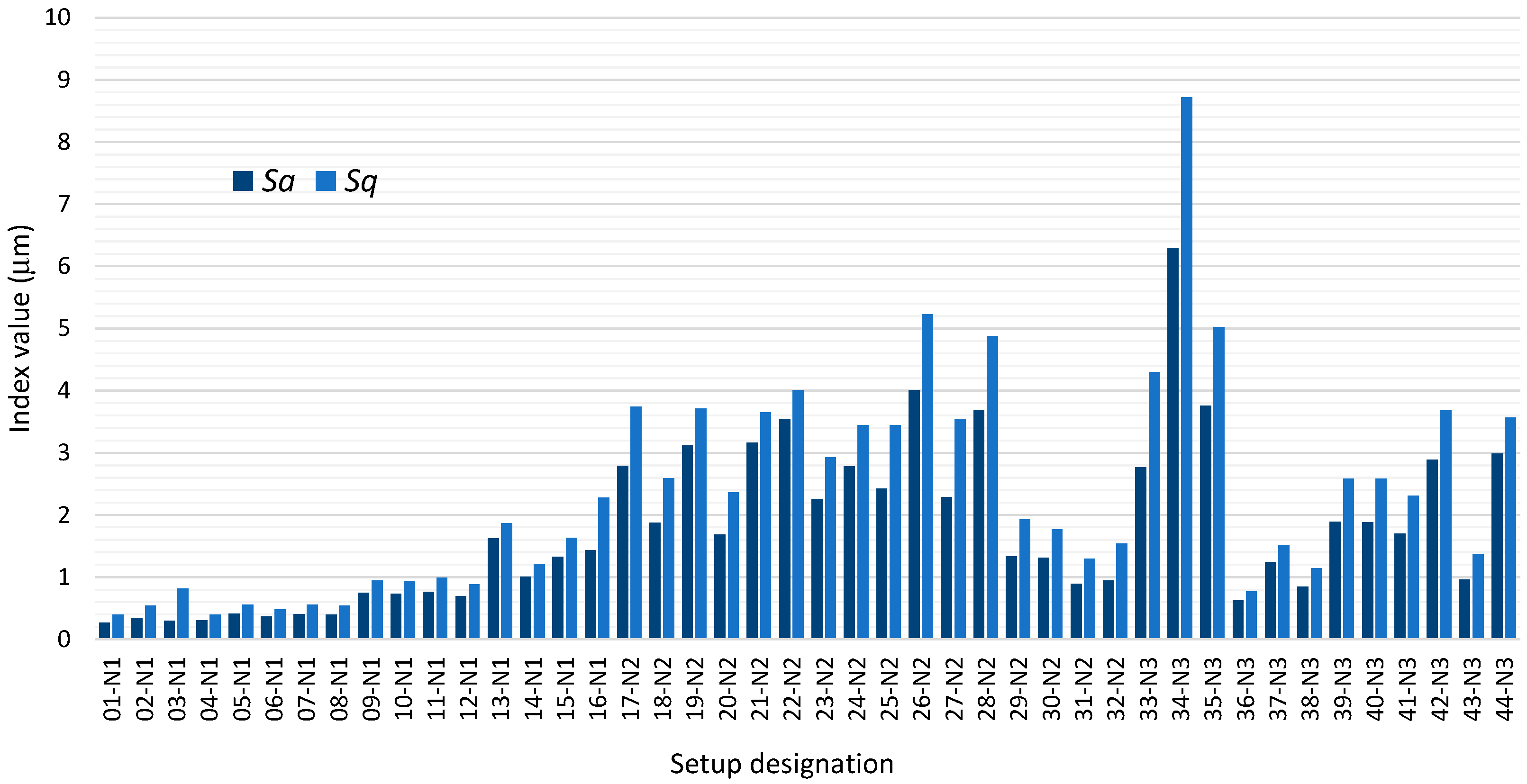
3.2. Indices of Geometric Condition of the Tested Surfaces
- Sa—arithmetic mean deviation of the surface points from the mean line (μm);
- Sq—mean square deviation of the surface points from the mean line (μm).
- Sp—maximum peak height (µm);
- Sv—maximum valley depth (µm).
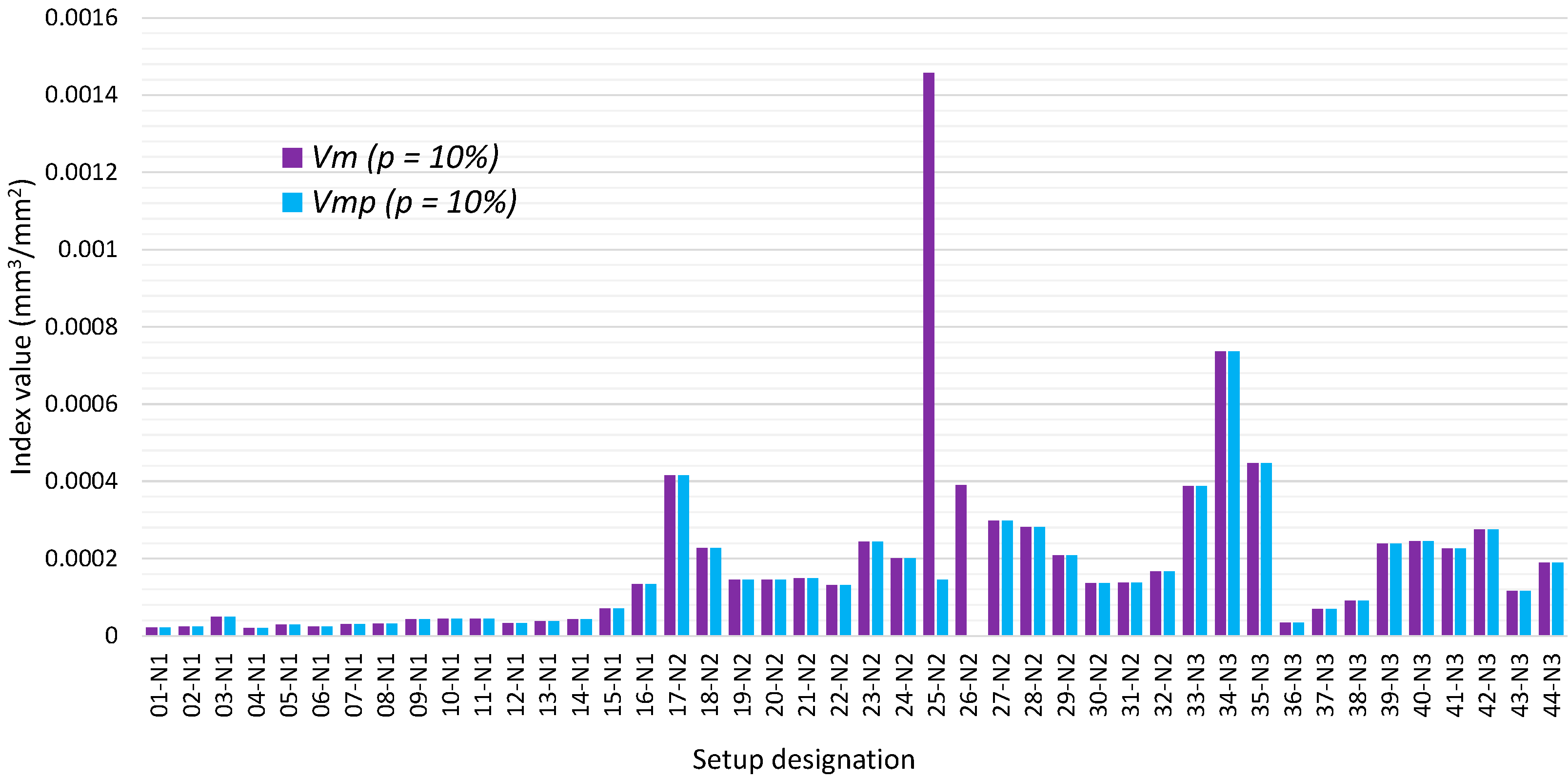
- Vm(p)—material volume at material ratio p expressed as a percentage (mm3/mm2);
- Vmp—material volume in the hill region (mm3/mm2);
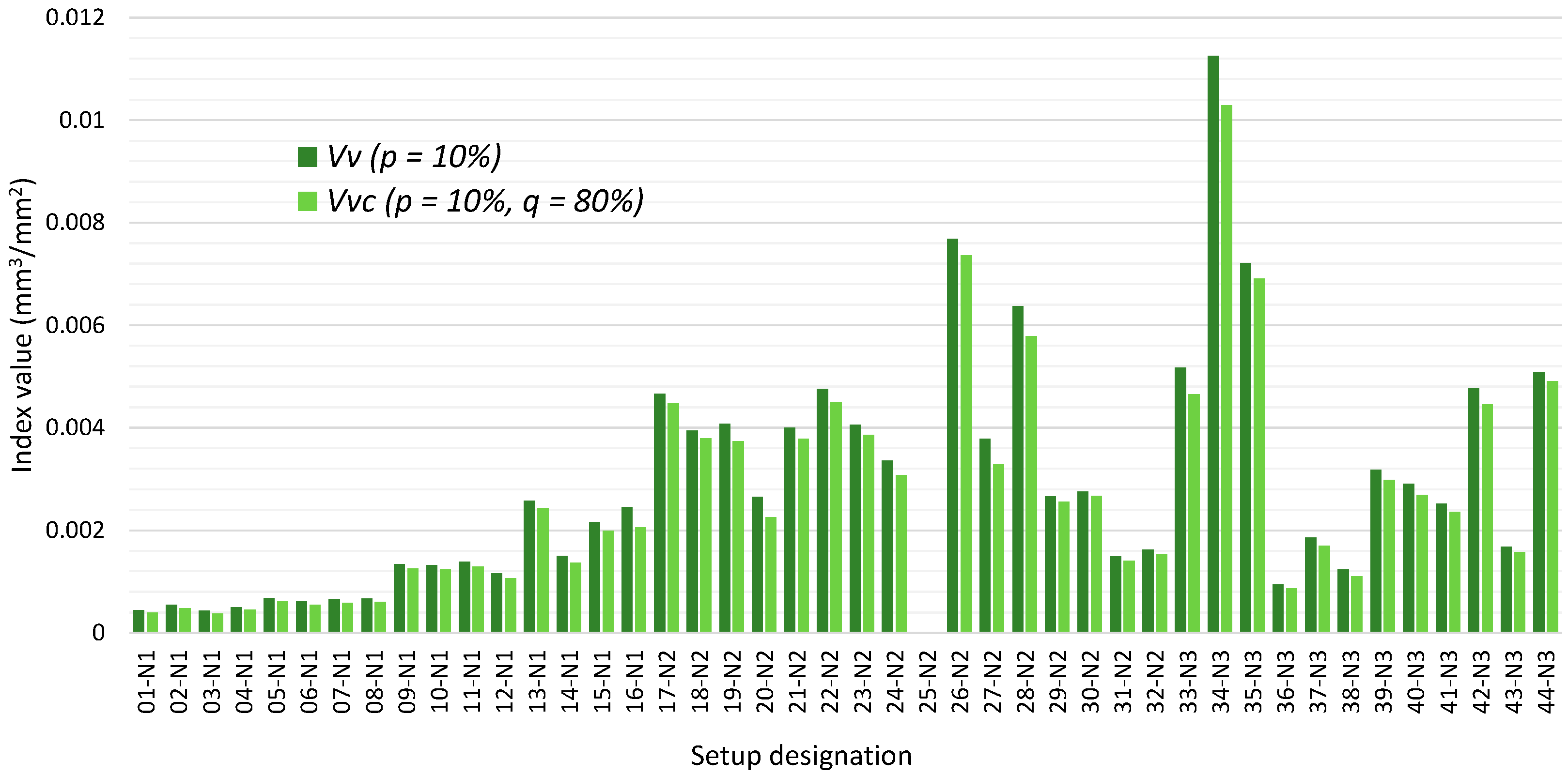
- Vv(p)—void volume at material ratio p expressed as a percentage (mm3/mm2);
- Vvc—void volume within the core (mm3/mm2);
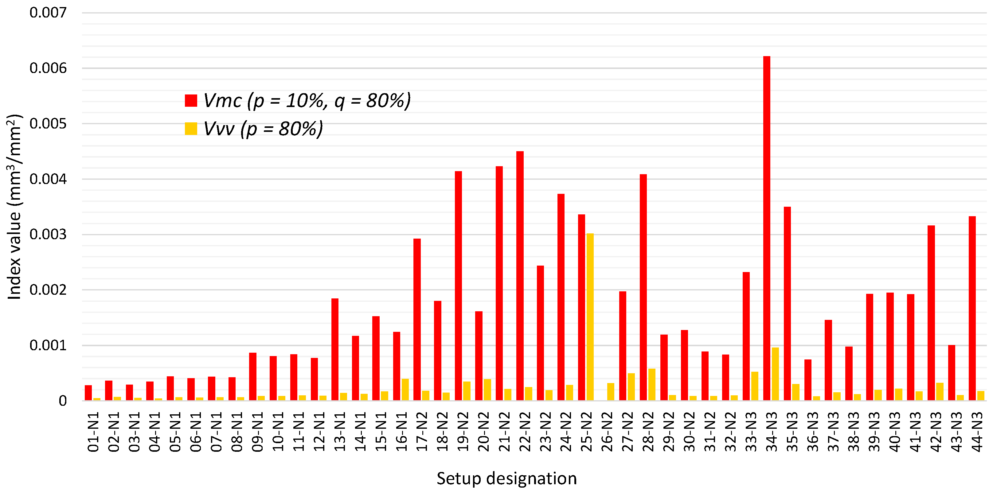
- Vmc—material volume within the core (mm3/mm2);
- Vvv—void volume below the core (mm3/mm2).
3.3. Surface Wettability
- Sbi—surface bearing capacity index (no unit);
- Sci—surface core fluid retention index (no unit);
- Svi—surface valley fluid retention index (no unit).
4. Discussion
4.1. Surface Maps
4.2. Indices of Geometric Condition of the Tested Surfaces
4.3. Surface Wettability
5. Conclusions
- Ductile cast iron alloys are characterised by good machinability in terms of the periodic cutting speed as well as the qualitative effects of the resulting surface;
- Good machinability translates into a stable machining process. Experimental work has shown that the machining process is stable over the entire range of machining parameters. Some difficulties (sensitivity of the process to the formation and development of self-excited vibrations) are noted under roughing conditions. The qualitative results of the surfaces obtained under these conditions in mechanical engineering are unsatisfactory. In such cases, it is noted that the values of the geometrical texture indices of the surface used as standard for defining the functionality of the part surface (e.g., Sa less than 3.2 µm and Sz less than 25 µm) are significantly exceeded;
- It is fairly easy to meet the surface quality requirements when cutting EN-GJS-600-3 ductile cast iron under finishing conditions. The material aspects associated with the disruption of the cutting process, which is caused by ferrite in ball form [53], do not contribute significantly to the reduction of the surface geometrical structure indices. The process is stable, and the surface condition is predictable;
- Layered inhomogeneities and inclusions present in the cast iron alloy contribute significantly to the quality of the machinable surface. The rearrangement in the deeper layers beneath the product surface results in the detection during the shaping and finishing milling of cracks and pores that were previously not visible. Visible surface faults occur, especially in the softer graphite phases contributing to surface burrs and collapse. An increase in surface roughness height is thus observed as the feed and depth of cut are changed in combination with a constant cutting speed;
- As a result of an inadequate material structure, the cutting process can become uncontrollable, but this does not necessarily imply a deterioration in machinability as assessed by the criterion of a high periodic cutting speed;
- The surface of machined cast iron is characterised by a relatively small number of high peaks, which contribute to a reduction in its load-bearing capacity. Machine and equipment parts manufactured from this material must initially be lapped, or lapping (and/or honing) treatments must be designed into the process to reduce these peaks;
- The milled surfaces of cast iron parts are characterised by satisfactory fluid retention values, and the large volume spaces created during the cutting of softball graphite phases (in the core and valley bottoms) become pockets in which lubricant can accumulate (thus improving the self-lubricating properties of the mating product surfaces).
Author Contributions
Funding
Institutional Review Board Statement
Informed Consent Statement
Data Availability Statement
Conflicts of Interest
References
- PN-EN 1563; Founding, Spheroidal Graphite Cast Irons. Polish Committee for Standardization: Warsaw, Poland, 2018.
- DIN 1693 GGG60 Ductile Cast Iron. Available online: https://www.iron-foundry.com/DIN-1693-GGG60-Ductile-Cast-Iron.html (accessed on 31 July 2024).
- Trauth, D.; Klocke, F.; Mattfeld, P.; Klink, A. Time-efficient prediction of the surface layer state after deep rolling using similarity mechanics approach. Procedia CIRP 2013, 9, 29–34. [Google Scholar] [CrossRef]
- Jost, B.; Klein, M.; Beck, T.; Eifler, D. Temperature dependent cyclic deformation and fatigue life of EN-GJS-600 (ASTM 80-55-06) ductile cast iron. Int. J. Fatigue 2017, 96, 102–113. [Google Scholar] [CrossRef]
- Karaca, B.; Simsir, M. The effects of austempering and induction hardening on the wear properties of camshaft made of ductile cast iron. Acta Phys. Pol. A 2017, 131, 448–452. [Google Scholar] [CrossRef]
- Benedetti, M.; Curtolo, T.; Dallago, M.; Fontanari, V.; Lusuardi, D. Yield and fracture loci for a ductile cast iron EN-GJS-600–3 under biaxial stresses. Fatigue Fract. Eng. Mater. Struct. 2022, 45, 783–800. [Google Scholar] [CrossRef]
- Şeker, U.; Hasirci, H. Evaluation of machinability of austempered ductile irons in terms of cutting forces and surface quality. J. Mater. Process. Technol. 2006, 173, 260–268. [Google Scholar] [CrossRef]
- Chihaoui, S.; Yallese, M.A.; Belhadi, S.; Belbah, A.; Safi, K.; Haddad, A. Coated CBN cutting tool performance in green turning of gray cast iron EN-GJL-250: Modeling and optimization. Int. J. Adv. Manuf. Technol. 2021, 113, 3643–3665. [Google Scholar] [CrossRef]
- Benedetti, M.; Santus, C.; Fontanari, V.; Lusuardi, D.; Zanini, F.; Carmignato, S. Plain and notch fatigue strength of thick-walled ductile cast iron EN-GJS-600-3: A double-notch critical distance approach to defect sensitivity. Int. J. Fatigue 2021, 152, 106414. [Google Scholar] [CrossRef]
- Linn, A.; Wächter, M.; Esderts, A. On how S-N curves for nonproportional loading can be determined from S-N curves for proportional loading—An exemplary evaluation of numerous fatigue tests using scaled normal stresses. Int. J. Fatigue 2024, 188, 108505. [Google Scholar] [CrossRef]
- Grzejda, R. Modelling Nonlinear Multi-Bolted Connections: A Case of the Assembly Condition. In Proceedings of the 15th International Scientific Conference ‘Engineering for Rural Development 2016’, Jelgava, Latvia, 25–27 May 2016; pp. 329–335. [Google Scholar]
- Grzejda, R. Modelling Nonlinear Multi-Bolted Connections: A Case of Operational Condition. In Proceedings of the 15th International Scientific Conference ‘Engineering for Rural Development 2016’, Jelgava, Latvia, 25–27 May 2016; pp. 336–341. [Google Scholar]
- Grzejda, R. New method of modelling nonlinear multi-bolted systems. In Advances in Mechanics: Theoretical, Computational and Interdisciplinary Issues, 1st ed.; Kleiber, M., Burczyński, T., Wilde, K., Gorski, J., Winkelmann, K., Smakosz, Ł., Eds.; CRC Press: Leiden, The Netherlands, 2016; pp. 213–216. [Google Scholar]
- Grzejda, R.; Parus, A. Health assessment of a multi-bolted connection due to removing selected bolts. FME Trans. 2021, 49, 634–642. [Google Scholar] [CrossRef]
- Klimek, L.; Gumienny, G.; Januszewicz, B.; Atraszkiewicz, R.; Buczkowska, K. Structural and phase analysis of the ausferritic ductile cast iron matrix obtained by heat treatment and in the raw state. J. Carbon Res. 2024, 10, 45. [Google Scholar] [CrossRef]
- Padmakumar, M.; Arunachalam, M. Analyzing the effect of cutting parameters and tool nose radius on forces, machining power and tool life in face milling of ductile iron and validation using finite element analysis. Eng. Res. Express 2020, 2, 035003. [Google Scholar] [CrossRef]
- Moreno, J.R.S.; Ribeiro, A.A.; de Souza Gonçalves, J.F. Comparative analysis on the wear performance of new and reconditioned ceramic cutting tools when machining nodular cast iron GGG-60, with lubrication of two types of fluids. J. Mater. Eng. Perform. 2021, 30, 248–257. [Google Scholar] [CrossRef]
- Tungaloy Insert Converter. Available online: https://converter.tungaloy.com (accessed on 3 August 2024).
- Teke, I.T.; Oktay, M.; Baykara, C.; Ertas, A.H. Microstructure and surface roughness connection on machined ductile iron: An experimental determination. E3S Web Conf. 2024, 477, 00003. [Google Scholar] [CrossRef]
- Baek, D.K.; Ko, T.J.; Kim, H.S. Optimization of feedrate in a face milling operation using a surface roughness model. Int. J. Mach. Tools Manuf. 2001, 41, 451–462. [Google Scholar] [CrossRef]
- Lee, K.Y.; Kang, M.C.; Jeong, Y.H.; Lee, D.W.; Kim, J.S. Simulation of surface roughness and profile in high-speed end milling. J. Mater. Process. Technol. 2001, 113, 410–415. [Google Scholar] [CrossRef]
- Simunovic, G.; Simunovic, K.; Saric, T. Modelling and simulation of surface roughness in face milling. Int. J. Simul. Model. 2013, 12, 141–153. [Google Scholar] [CrossRef]
- Felhő, C.; Karpuschewski, B.; Kundrák, J. Surface roughness modelling in face milling. Procedia CIRP 2015, 31, 136–141. [Google Scholar] [CrossRef]
- Denkena, B.; Dittrich, M.-A.; Huuk, J. Simulation-based surface roughness modelling in end milling. Procedia CIRP 2021, 99, 151–156. [Google Scholar] [CrossRef]
- Kumar, K.M.; Arun, K.; Sathishkumar, N.; Pathri Narayanan, M.; Raviraj, E. Experimental investigation on the machinability of nodular ductile iron with cubic boron nitride and tungsten carbide inserts. Mater. Today Proc. 2021, 39, 1386–1389. [Google Scholar] [CrossRef]
- Binali, R.; Kuntoğlu, M. An in-depth analysis on the surface roughness variations during turning of GGG50 ductile cast iron. J. Sci. East 2022, 5, 41–49. [Google Scholar] [CrossRef]
- Cakir, M.C.; Bayram, A.; Kircali, K.K.; Ensarioglu, C. Effects of microstructure on machinability of ductile iron. Proc. Inst. Mech. Eng. Part B J. Eng. Manuf. 2011, 225, 297–304. [Google Scholar] [CrossRef]
- Aşkun, Y.; Hasirci, H.; Şeker, U. Evaluation of machinability of ductile irons alloyed with Ni and Cu in terms of cutting forces and surface quality. Pamukkale Univ. J. Eng. Sci. 2003, 9, 191–199. [Google Scholar]
- Nozdrzykowski, K.; Chybowski, L.; Dorobczyński, L. Model-based estimation of the reaction forces in an elastic system supporting large-size crankshafts during measurements of their geometric quantities. Measurement 2020, 155, 107543. [Google Scholar] [CrossRef]
- Chybowski, L.; Nozdrzykowski, K.; Grządziel, Z.; Dorobczyński, L. Evaluation of model-based control of reaction forces at the supports of large-size crankshafts. Sensors 2020, 20, 2654. [Google Scholar] [CrossRef] [PubMed]
- Nozdrzykowski, K.; Grządziel, Z.; Dunaj, P. Determining geometrical deviations of crankshafts with limited detection possibilities due to support conditions. Measurement 2022, 189, 110430. [Google Scholar] [CrossRef]
- Krajewski, S.J.; Grochała, D.; Tomków, J.; Grzejda, R. Analysis of the surface stereometry of alloyed austenitic steel after fibre laser cutting using confocal microscopy. Coatings 2023, 13, 15. [Google Scholar] [CrossRef]
- Grochała, D.; Grzejda, R.; Parus, A.; Berczyński, S. The wavelet transform for feature extraction and surface roughness evaluation after micromachining. Coatings 2024, 14, 210. [Google Scholar] [CrossRef]
- Sługocka, M.; Grochała, D.; Kwiatkowski, K.; Grzejda, R.; Zmarzły, P. Study of the impact of surface topography on selected mechanical properties of adhesive joints. Coatings 2024, 14, 944. [Google Scholar] [CrossRef]
- Zhang, J.Z.; Chen, J.C.; Kirby, E.D. Surface roughness optimization in an end-milling operation using the Taguchi design method. J. Mater. Process. Technol. 2007, 184, 233–239. [Google Scholar] [CrossRef]
- Ghani, A.K.; Choudhury, I.A.; Husni. Study of tool life, surface rough ness and vibration in machining nodular cast iron with ceramic tool. J. Mater. Process. Technol. 2002, 127, 17–22. [Google Scholar] [CrossRef]
- Sarma, D.K.; Dixit, U.S. A comparison of dry and air-cooled turning of grey cast iron with mixed oxide ceramic tool. J. Mater. Process. Technol. 2007, 190, 160–172. [Google Scholar] [CrossRef]
- Yücel, E.; Günay, M. Modelling and optimization of the cutting conditions in hard turning of high-alloy white cast iron (Ni-Hard). Proc. Inst. Mech. Eng. Part C J. Mech. Eng. Sci. 2013, 227, 2280–2290. [Google Scholar] [CrossRef]
- Günay, M.; Yücel, E. Application of Taguchi method for determining optimum surface roughness in turning of high-alloy white cast iron. Measurement 2013, 46, 913–919. [Google Scholar] [CrossRef]
- Kulkarni, P.P.; Kiran, J.O.; Deeleepkumar, S.G. Effect of tool nose radius and cutting parameters on tool life, surface roughness in turning of grey cast iron. Int. J. Eng. Sci. Technol. 2014, 6, 69–75. [Google Scholar]
- Ramji, B.R.; Narasimha Murthy, H.N.; Krishna, M. Analysis of roughness and flank wear in turning gray cast iron using cryogenically treated cutting tools. Res. J. Appl. Sci. Eng. Technol. 2010, 2, 414–417. [Google Scholar]
- Laouissi, A.; Yallese, M.A.; Belbah, A.; Khellaf, A.; Haddad, A. Comparative study of the performance of coated and uncoated silicon nitride (Si3N4) ceramics when machining EN-GJL-250 cast iron using the RSM method and 2D and 3D roughness functional parameters. J. Braz. Soc. Mech. Sci. Eng. 2019, 41, 205. [Google Scholar] [CrossRef]
- PN-EN 1561; Founding, Grey cast irons. Polish Committee for Standardization: Warsaw, Poland, 2024.
- PN-EN ISO 25178-1; Geometrical Product Specifications (GPS), Surface Texture: Areal, Part 1: Indication of Surface Texture. Polish Committee for Standardization: Warsaw, Poland, 2016.
- PN-EN ISO 25178-2; Geometrical Product Specifications (GPS), Surface Texture: Areal, Part 2: Terms, Definitions and Surface Texture Parameters. Polish Committee for Standardization: Warsaw, Poland, 2022.
- PN-EN ISO 25178-3; Geometrical Product Specifications (GPS), Surface Texture: Areal, Part 3: Specification Operators. Polish Committee for Standardization: Warsaw, Poland, 2012.
- Franco, L.A.; Sinatora, A. 3D surface parameters (ISO 25178-2): Actual meaning of Spk and its relationship to Vmp. Precis. Eng. 2015, 40, 106–111. [Google Scholar] [CrossRef]
- Podulka, P.; Macek, W.; Rozumek, D.; Żak, K.; Branco, R. Topography measurement methods evaluation for entire bending-fatigued fracture surfaces of specimens obtained by explosive welding. Measurement 2024, 224, 113853. [Google Scholar] [CrossRef]
- Sun, J.; Zhao, W.; Yan, P.; Wang, P.; Jiao, L.; Wang, X. Effect of cutting parameters on cutting performance of nodular cast iron in ultra-fine-pitched milling. Int. J. Adv. Manuf. Technol. 2022, 121, 4387–4402. [Google Scholar] [CrossRef]
- Ilori, O.O.; Oyewusi, T.F.; Fadare, O.A.; Adeyemi, F.F. Characterization and impact of cutting parameters on face-milled surfaces of pearlitic ductile iron. Niger. J. Technol. Dev. 2024, 21, 32–41. [Google Scholar] [CrossRef]
- Iacoviello, F.; Iacoviello, D.; Di Cocco, V.; De Santis, A.; D’Agostino, L. Classification of ductile cast iron specimens based on image analysis and support vector machine. Procedia Struct. Integr. 2017, 3, 283–290. [Google Scholar] [CrossRef]
- Buljac, A.; Helfen, L.; Hild, F.; Morgeneyer, T.F. Effect of void arrangement on ductile damage mechanisms in nodular graphite cast iron: In situ 3D measurements. Eng. Fract. Mech. 2018, 192, 242–261. [Google Scholar] [CrossRef]
- Savkovic, B.; Kovac, P.; Dudic, B.; Gregus, M.; Rodic, D.; Strbac, B.; Dudic, N. Comparative characteristics of ductile iron and austempered ductile iron modeled by neural network. Materials 2019, 12, 2864. [Google Scholar] [CrossRef] [PubMed]


| Tool Type | Diameter (mm) | Number of Tool Blades | Tool Overhang (mm) | Insert Type | Casing Type |
|---|---|---|---|---|---|
| N1 | 16 | 4 | 75 | R390-11T3 04M-PM 4220 1 | Ø16 AEM90 R390.11 W16 L150 2 |
| N2 | 30 | 4 | 95 | R390-11T3 04M-PM 4220 1 | Ø30 AEM90 R390.11 W25 L150 2 |
| N3 | 6 | 4 | 25 | monolithic cutter | P8300300 3 |
| Parameter | Unit | Values |
|---|---|---|
| cutting speed | (mm/min) | 100 |
| depth of cut | (mm) | 0.5, 1.0 |
| wrapping angle | (°) | 120, 180 |
| feed per blade | (mm/blade) | 0.01, 0.05, 0.1, 0.3 1 |
| Tool Type | Length of Measuring Axis in X Direction (mm) | X-Axis Point Spacing (μm) | Length of Measuring Axis in Y Direction (mm) | Y-Axis Point Spacing (μm) | Average Number of Non-Measured Points (%) | Point Cloud Size (MPx) |
|---|---|---|---|---|---|---|
| N1 | 1.04 | 0.197 | 1.08 | 0.198 | 3.05 | 28.7 |
| N2 | 1.54 | 0.197 | 1.54 | 0.198 | 1.62 | 60.7 |
| N3 | 1.54 | 0.197 | 1.54 | 0.198 | 0.88 | 60.7 |
Disclaimer/Publisher’s Note: The statements, opinions and data contained in all publications are solely those of the individual author(s) and contributor(s) and not of MDPI and/or the editor(s). MDPI and/or the editor(s) disclaim responsibility for any injury to people or property resulting from any ideas, methods, instructions or products referred to in the content. |
© 2024 by the authors. Licensee MDPI, Basel, Switzerland. This article is an open access article distributed under the terms and conditions of the Creative Commons Attribution (CC BY) license (https://creativecommons.org/licenses/by/4.0/).
Share and Cite
Grochała, D.; Jasiewicz, M.; Filipowicz, K.; Parus, A.; Powałka, B.; Grzejda, R.; Zmarzły, P. Assessment of the Functional Properties of the Surfaces of Ductile Cast Iron Parts. Appl. Sci. 2024, 14, 9129. https://doi.org/10.3390/app14199129
Grochała D, Jasiewicz M, Filipowicz K, Parus A, Powałka B, Grzejda R, Zmarzły P. Assessment of the Functional Properties of the Surfaces of Ductile Cast Iron Parts. Applied Sciences. 2024; 14(19):9129. https://doi.org/10.3390/app14199129
Chicago/Turabian StyleGrochała, Daniel, Marcin Jasiewicz, Krzysztof Filipowicz, Arkadiusz Parus, Bartosz Powałka, Rafał Grzejda, and Paweł Zmarzły. 2024. "Assessment of the Functional Properties of the Surfaces of Ductile Cast Iron Parts" Applied Sciences 14, no. 19: 9129. https://doi.org/10.3390/app14199129
APA StyleGrochała, D., Jasiewicz, M., Filipowicz, K., Parus, A., Powałka, B., Grzejda, R., & Zmarzły, P. (2024). Assessment of the Functional Properties of the Surfaces of Ductile Cast Iron Parts. Applied Sciences, 14(19), 9129. https://doi.org/10.3390/app14199129