Article

Advanced Metamaterial-Integrated Dipole Array Antenna for Enhanced Gain in 5G Millimeter-Wave Bands

1
Department of Information and Communication Engineering, Chungbuk National University, Cheongju 28644, Republic of Korea
2
Chungbuk Technopark, Chungju 27465, Republic of Korea
*
Author to whom correspondence should be addressed.
Appl. Sci. 2024, 14(19), 9138; https://doi.org/10.3390/app14199138
Submission received: 9 September 2024 / Revised: 3 October 2024 / Accepted: 8 October 2024 / Published: 9 October 2024
(This article belongs to the Section Electrical, Electronics and Communications Engineering)

Abstract

:
A metamaterial-based non-uniform dipole array antenna is presented for high gain 5G millimeter-wave applications with a wideband characteristic. Initially, a non-uniform dipole array is designed on a 0.202 mm thick Rogers RO4003C substrate, offering a wide operating bandwidth ranging from 23.1 GHz to 44.8 GHz. The dipole array antenna emits unidirectional end-fire radiation with a maximum gain of 8.1 dBi and an average gain of 6.7 dBi. Subsequently, to achieve high gain performance, a 5 × 7 metamaterial structure is designed in the direction of the antenna radiation. The implemented metamaterial structure is optimized for the operating frequency, enhancing the directivity of the antenna radiation and resulting in a gain increment of more than 3 dBi compared to the dipole array alone. The developed metamaterial-integrated dipole array antenna offers an operating bandwidth (S11 < −10 dB) of more than 21 GHz (63.92%), ranging from 23.1 GHz to 44.8 GHz, covering the most commonly used 5G millimeter-wave frequency bands (n257, n258, n259, n260, and n261). Furthermore, the presented antenna yields a stable high gain with a peak gain of 11.21 dBi and a good radiation efficiency of more than 64%. The proposed antenna is an excellent option for millimeter-wave 5G systems due to its overall properties, particularly its high gain and end-fire radiation characteristics, combined with a wide operating bandwidth.

1. Introduction

In recent years, there has been a noticeable increase in research and development in the high-frequency domain, specifically the millimeter-wave (mmWave) frequency band [1,2,3]. This surge is a part of a continuous pursuit to surpass the limitations of data transmission speed and network capacity, with a particular focus on the development of the next-generation mobile communication system, 5G. 5G promises not only superior speed compared to existing 4G LTE (Long-Term Evolution) systems but also lower latency and higher data rates over a wider frequency range [4,5]. 5G technology is designed to support various data-intensive applications such as autonomous vehicles, artificial intelligence, and the Internet of Things (IoT), all of which require high-speed internet connections [6]. The recent and upcoming 5G millimeter-wave applications are demonstrated in Figure 1.
One of the core technologies of the 5G network is New Radio (NR) technology, which utilizes the millimeter-wave frequency band ranging from 24 GHz to 86 GHz [7]. This frequency band, largely unused by previous generations of mobile communication systems, offers a very wide bandwidth that theoretically enables gigabit-level ultra-high-speed data transmission [8,9,10]. The use of such a wide bandwidth solves potential capacity issues faced by future wireless communications, providing a foundation for uninterrupted connectivity and ultra-fast data services to users [11]. Many countries have already considered or chosen the 26/28 GHz band for the construction of 5G networks, playing a crucial role in accelerating the global standardization and commercialization of 5G services [12,13].
However, utilizing the millimeter-wave band comes with several challenges. Notably, the mm wave frequency band experiences relatively high propagation losses due to physical limitations such as attenuation by atmospheric molecules. To overcome these issues, communication systems require technical solutions such as high-gain antennas [14,15,16]. Recently, innovative antenna design methods have been proposed to enhance the performance of the millimeter-wave antenna [17,18,19,20,21,22,23,24,25,26,27,28]. A quasi-Yagi array antenna with a folded dipole driver is proposed for 5G mm wave applications in [17], while a series-fed antenna array is proposed in [18] for high antenna gain. However, the antennas in both [17] and [18] suffer from narrow operating bandwidths. In [19], a partially reflective surface (PRS) is utilized with a Fabry–Perot cavity antenna to achieve high gain operating at the 60 GHz band, but this antenna occupies a larger space because of its double substrate layers with additional foam layers in between the substrate layers. Additionally, a log-periodic dipole array with director cells [20], planar segmented techniques [21], metasurface layers [22], slot antennas with substrate-integrated waveguides [23], defected ground antennas with metallic vias [24], and clover-type antenna array techniques are utilized in the literature to enhance the performance the of millimeter-wave antennas [25]. However, these antennas either suffer from a large overall antenna volume [21,22,23] or very low antenna gain [24,25,26].
Besides the above-mentioned techniques, metamaterial is also becoming popular among researchers to enhance the performance of millimeter-wave antennas [27,28,29] because of its capability to enhance the gain and bandwidth of antennas. In [27], a metamaterial layer is utilized 16 mm above the designed patch antenna to increase the antenna gain. Likewise, in [28,29], metamaterial is used to achieve high antenna gain. These reported works [27,28,29] achieve high antenna gain; however, all of these works have the limitation of a narrow bandwidth. Additionally, the antenna in [27] suffers from a large antenna volume.
In this work, a high-gain millimeter-wave antenna is proposed based on metamaterial. At first, an array of non-uniform dipoles is designed to provide a broad operational bandwidth within the millimeter-wave frequency range. The dipole array antenna provides a wider bandwidth and end-fire radiation characteristics with lower gain. To improve the gain of the designed dipole array, a metamaterial array structure is proposed. By utilizing the proposed metamaterial structure, the gain is improved by more than 3 dBi. To validate the proposed work, a prototype of the designed antenna is manufactured and tested. The proposed method is also validated by the measurement results. The rest of the manuscript is organized as follows: The antenna design methods and design procedure are explained in detail in Section 2. The results of the proposed antenna are presented in Section 3 along with the performance analogy of the designed antenna. Finally, the proposed work is concluded in Section 4.

2. The Design of the Metamaterial-Integrated Dipole Antenna

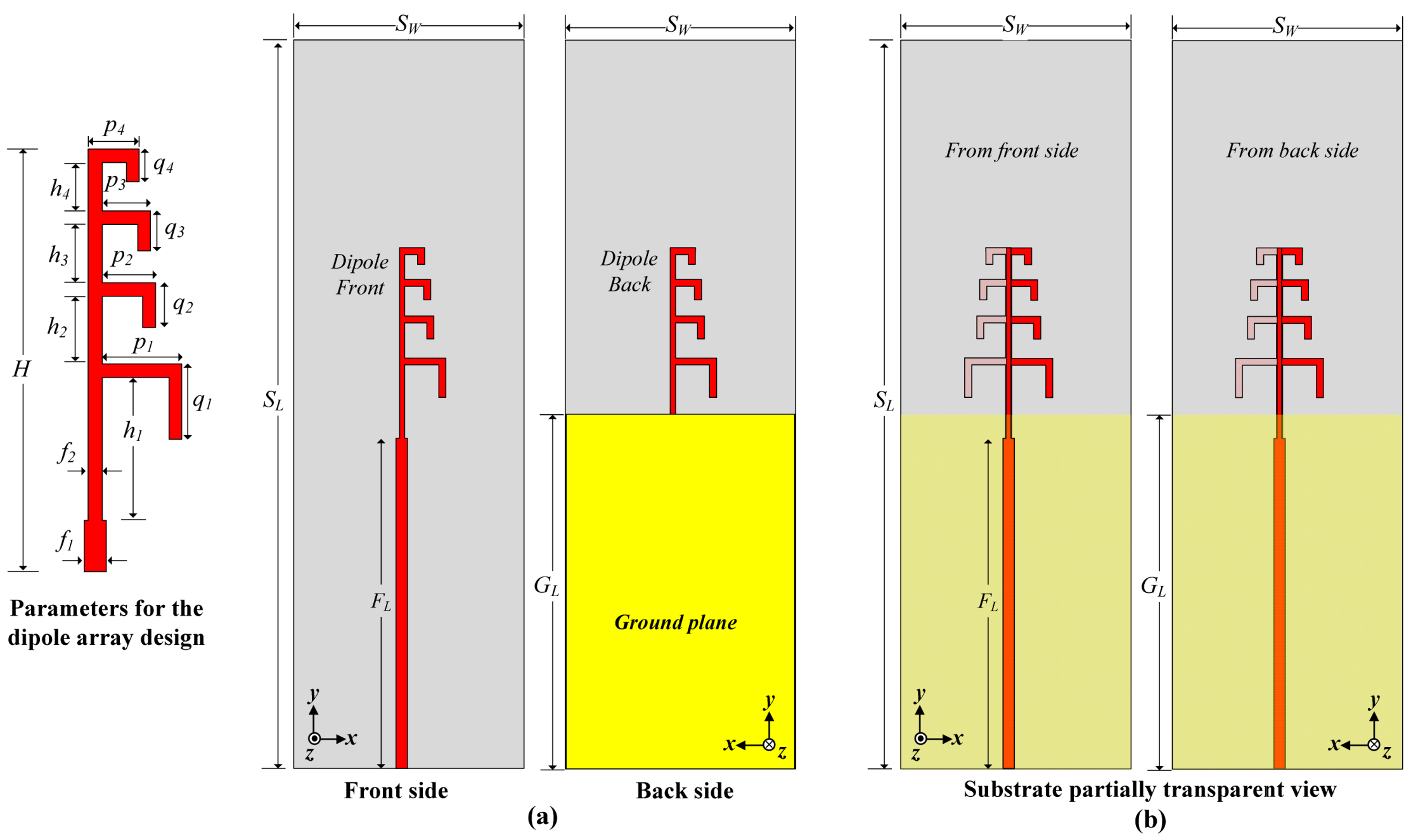
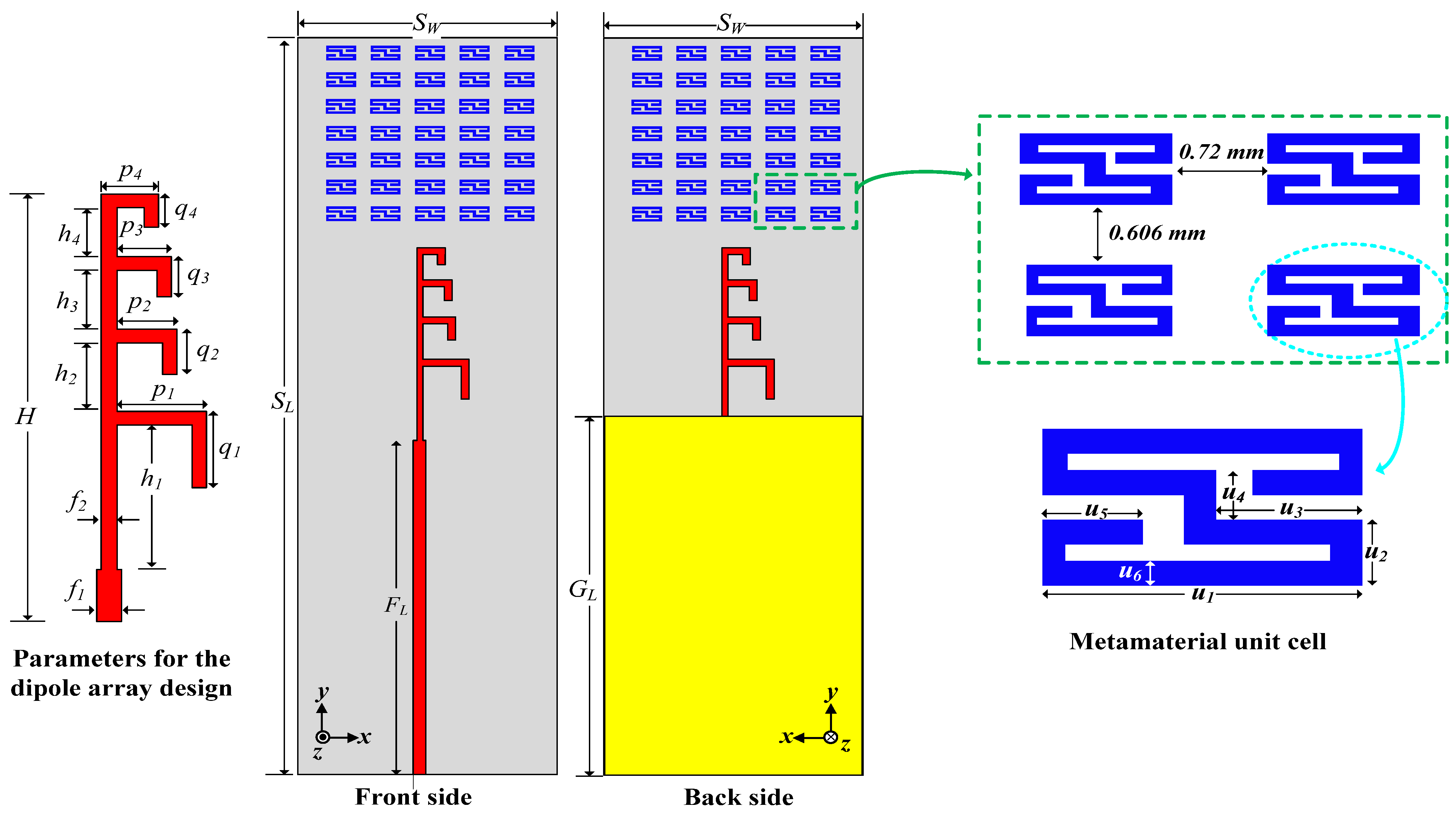
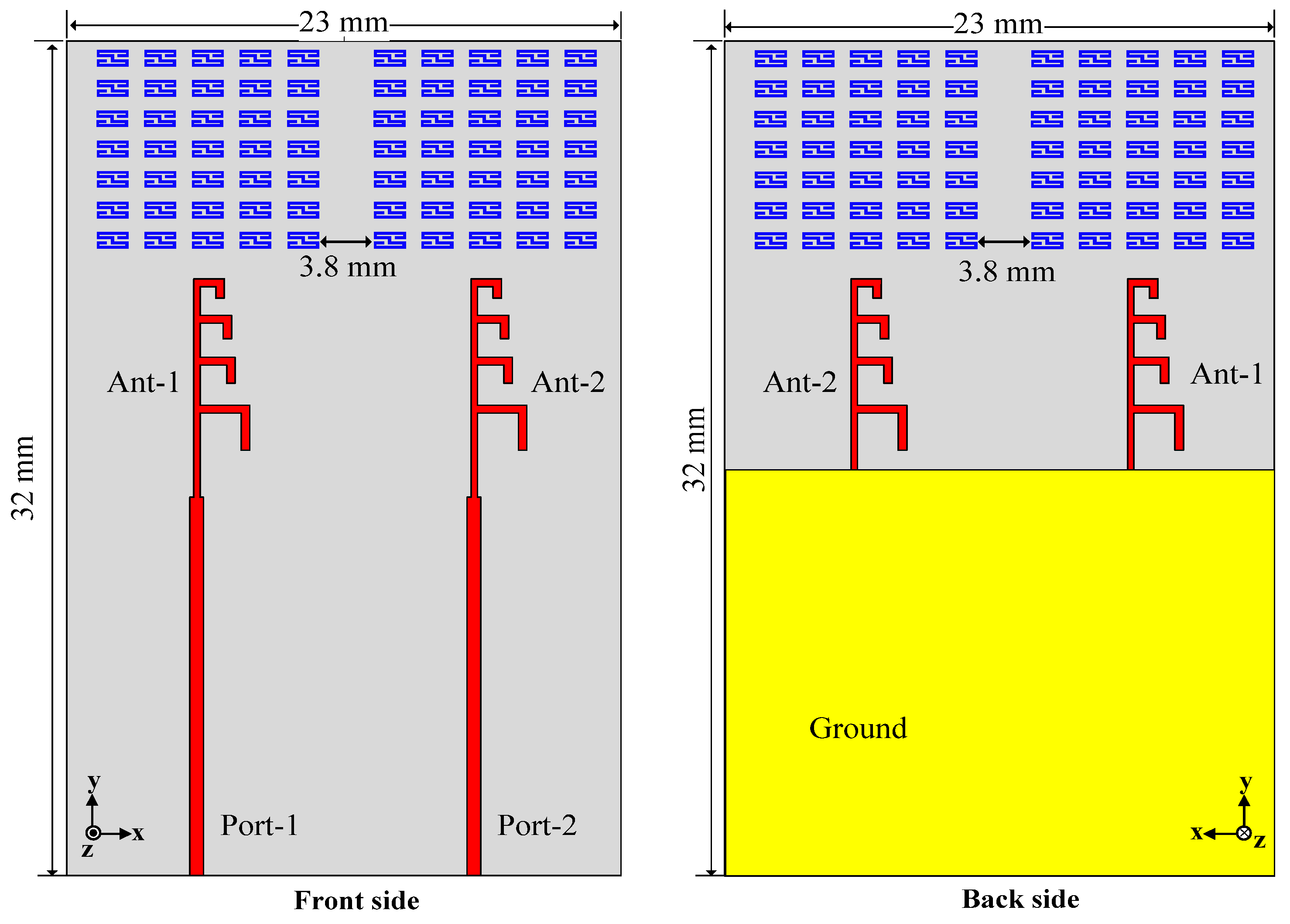
2.1. The Dipole Array Antenna Design

The array dipole antenna and its performance parameters are explained in this subsection. The initial dipole antenna is designed on a 32 mm × 10 mm Rogers RO4003C substrate with a thickness of 8 mils, a dielectric constant εr = 3.55, and a loss tangent δ = 0.0027. The dipole array antenna without the proposed metamaterial structure is depicted in Figure 2, and its design parameters are listed in Table 1. In this work, a partial ground plane is utilized instead of a full ground plane, as the end-fire radiation characteristic is targeted. Usually, with the full ground plane, the antenna offers a broadside radiation pattern [15]. In the proposed design, the half of the dipole array at the front side is connected to a feedline, and the other half of the dipole array at the back side is connected to the partial ground plane. The proposed antenna offers end-fire radiation with a very wide operating bandwidth, as shown in Figure 3. The designed dipole array yields a wide bandwidth, ranging from 23.2 GHz to 45.3 GHz. With a peak gain of 8.02 dBi and an average gain of 6.59 dBi, the proposed dipole array provides unidirectional end-fire radiation. In the simulation software, instead of an ideal port, a millimeter-wave connector is designed and connected to the antenna, as can be seen in Figure 3b and Figure 4. With this actual connector model, the results of the antenna after fabrication can be realized.
The surface current distribution of the dipole array antenna at different operating frequencies is also shown in Figure 4. It can be observed from the current distribution graph that the lower resonances are generated by the longer arms. At 26 GHz, the lower arms show a high level of current density. Similarly, the shorter arms are responsible for the higher band resonances. At 28 GHz, the middle arms show increased current density. Meanwhile, at 38 GHz, the highest current density is observed in the shortest arm of the dipole array.
A parametric study of the array dipole antenna is presented in Figure 5 only for the parameters P1 and P4 to show the controllability of the reflection coefficient of the designed antenna. It can be observed from the parametric study graph in Figure 5 that by controlling the P1 parameter, the resonance at the lower band can be controlled, and by controlling the P4 parameter, the upper operating frequency band can be controlled. Similarly, by controlling the other parameters of the dipole, the resonance of the antenna can be changed or improved.

2.2. Metamaterial Unit Cell Design

The metamaterial structures have the ability to interact with the electromagnetic waves of any antenna and change the antenna’s radiation performance [30]. As the dipole antenna alone offers a very low average gain of 6.7 dBi with a maximum peak gain of 8.1 dBi, a novel metamaterial structure is proposed to enhance the gain of the designed dipole antenna by boosting radiation directivity. Initially, a unit cell is developed for the targeted frequency spectrum. Afterwards, the unit cell is copied and translated to design the proposed metamaterial structure. The simulation setup and results of the designed unit cell, along with its dimensions, are presented in Figure 6. The dimensions of the developed unit cell are shown in Figure 6a, and the parametric values are listed in Table 2. Additionally, the working principle of the metamaterial is illustrated in Figure 6b, where ni and n0 represent the refractive index in the substrate and air, respectively. Snell’s law states the relation between ni and n0, as presented in Equation (1):
nisin(θi) = n0sin(θ0),
where θi is the angle of incidence and θ0 is the angle of refraction. This relationship clarifies how the artificial material guides electromagnetic waves, resulting in energy convergence. Whenever ni > 1, the energy transmitted through the material will be converged in air, resulting in highly directional radiation that consequently increases the gain of the antenna with end-fire radiation characteristics [31,32]. On the other hand, to increase the performance of the antenna with broadside radiation, the value of the refractive index should be zero or near zero [33].
Additionally, the characteristic responses and material properties are displayed in Figure 6c and Figure 6d, respectively. The fundamental parameters of a metamaterial unit cell are the effective permittivity (ϵ) and permeability (μ). These parameters can be expressed by Equation (2) and Equation (3), respectively [34].
ε = n z
μ = n z
Here, n represents the refractive index, and z is the impedance of the metamaterial. The parameters n and z can be easily calculated using Equations (4) and (5) [35,36] from the characteristic responses shown in Figure 6c, where the electromagnetic wave transmission (S21) and reflection (S11) characteristics are presented. Furthermore, k is the free-space wave impedance, d is the thickness of the virtual homogeneous slab which stands in for the actual geometry, m = 0, 1, 2, 3, …, and R 01 = ( z 1 ) / ( z + 1 ) .
z = ±   ( 1 + S 11 ) 2 S 21 2 ( 1 S 11 ) 2 S 21 2
n = 1 k 0 d I m l n s 21 1 s 11 R 01 + 2 m π i R e ln s 21 1 s 11 R 01
It can be observed from the material properties of the designed metamaterial unit cell, as shown in Figure 6d, that the meta-cell provides a non-resonant mode within the frequency range of 20–44 GHz by exhibiting a stable ε value around 8.2, while μ remains stable around 4.2. In this scenario, the refractive index of the metamaterial can be estimated from Equation (6), and the refractive index value is more than 1 within the targeted frequency band.
n i = ε i . μ i
Hence, the refractive index remains consistently above 1 within this specified region, and the directivity of the antenna is enhanced as per Snell’s law, as previously explained.

2.3. The Dipole Array Antenna with the Proposed Metamaterial Structure

After achieving a good response from the metamaterial unit cell for the targeted frequency band, the proposed metamaterial structure is employed at the top side of the dipole array, at both the front and back side, as presented in Figure 7, to enhance the performance, particularly in terms of high gain. The dipole array antenna is evaluated with a different number of unit cells for the best gain performance. Figure 8 contains the gain response of the dipole antenna with a different number of metamaterials. While Figure 8a shows the gain response of the variation in the cells in the horizontal position, Figure 8b presents the gain response of the varying cell numbers in the vertical arrangement. It can be observed from the gain graphs that the proposed 5 × 7 metamaterial structure offers the best gain performance, with a maximum gain of 11.21 dBi. The minimum and maximum gain responses of different metamaterial cell arrangements along with their corresponding frequency responses are presented in Table 3.

3. Antenna Results and Discussion

The performance parameters of the proposed metamaterial-based array dipole antenna are presented in this section. All of the antenna performance parameters, including the reflection coefficient, radiation characteristics, radiation efficiency, and gain, are suitable for wideband 5G NR millimeter-wave applications. The fabricated antenna prototype is shown in Figure 9a, while Figure 9b contains the measurement setup in an anechoic chamber [37] used for the antenna’s radiation characterization. The S-parameters of the proposed metamaterial-based dipole antenna are measured in a normal environment using the Keysight E8364B PNA network analyzer. The far field is measured in an anechoic chamber, as shown in Figure 9b, while a horn antenna with standard performance is used as the transmitting antenna, and the proposed antenna receives the signal as a receiver.

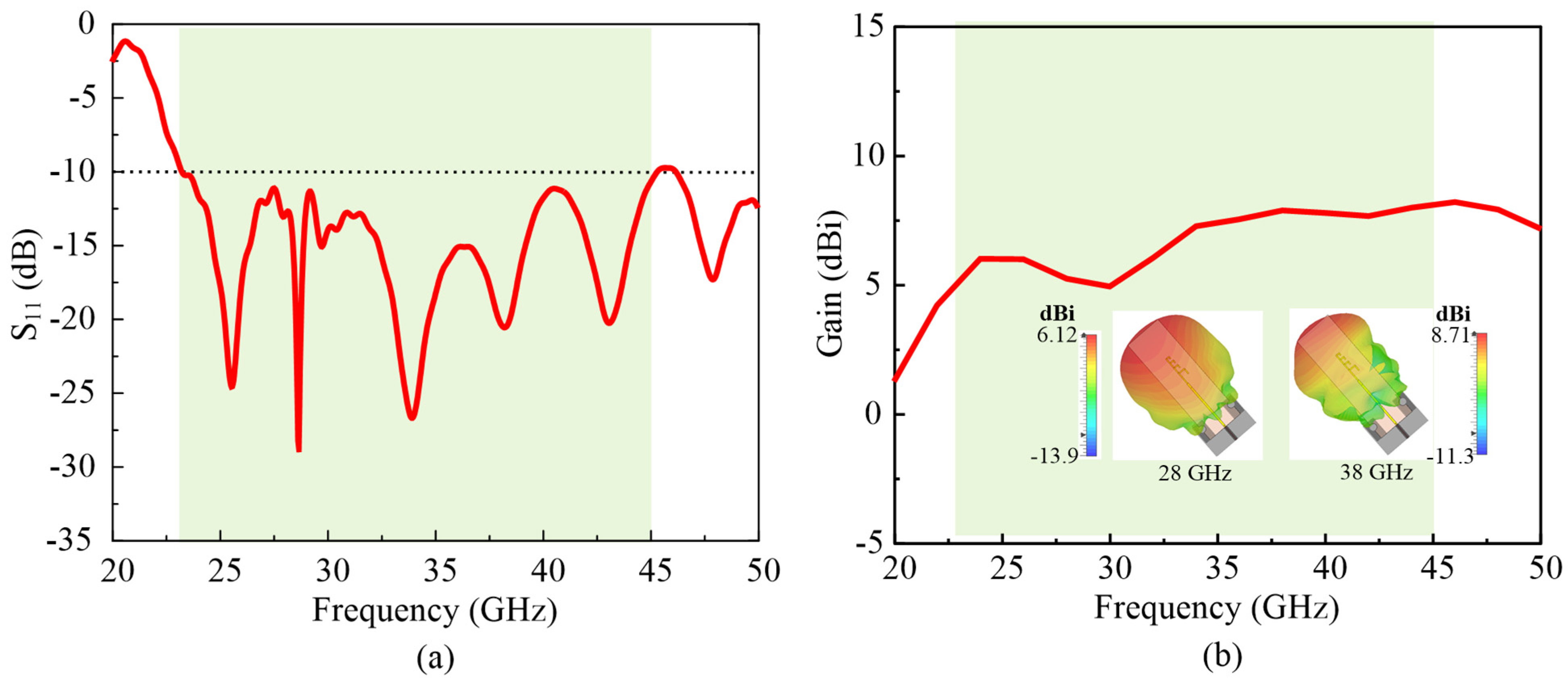
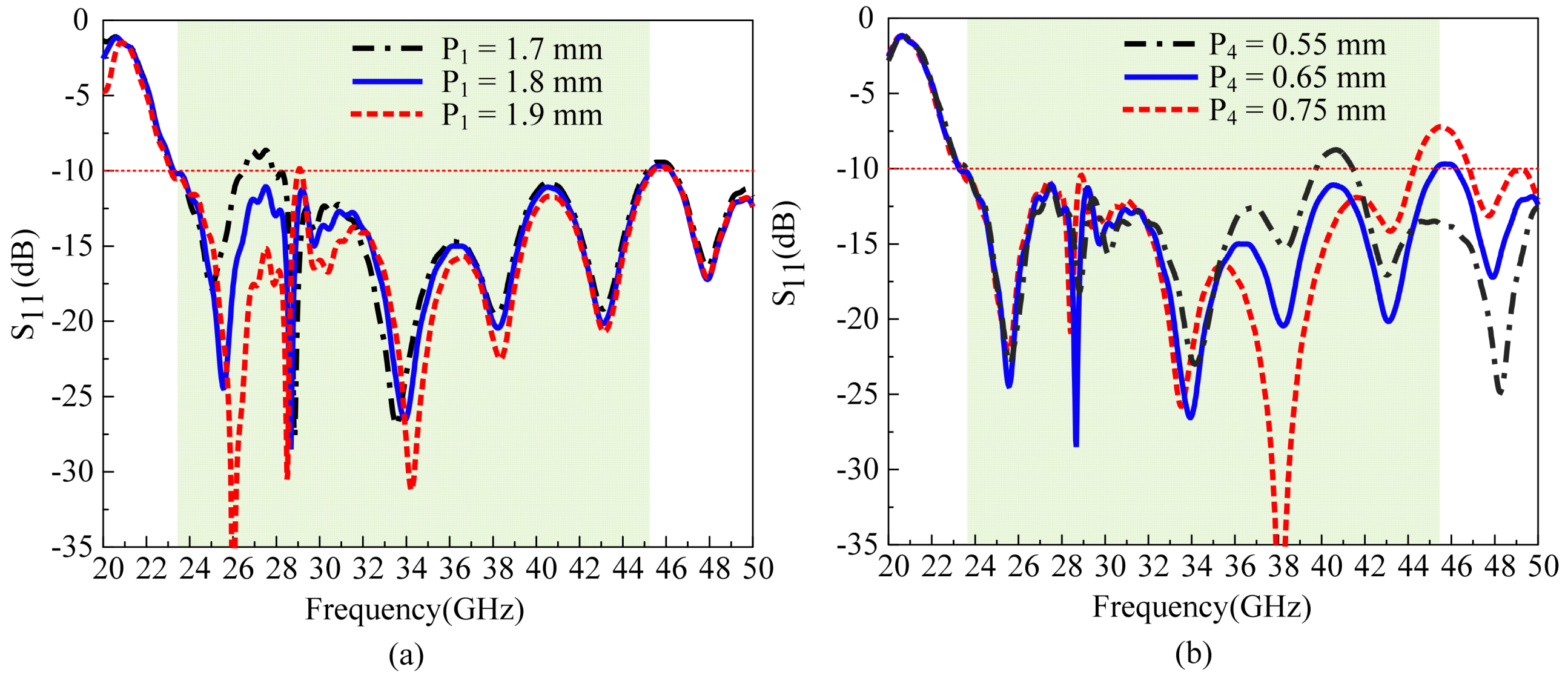
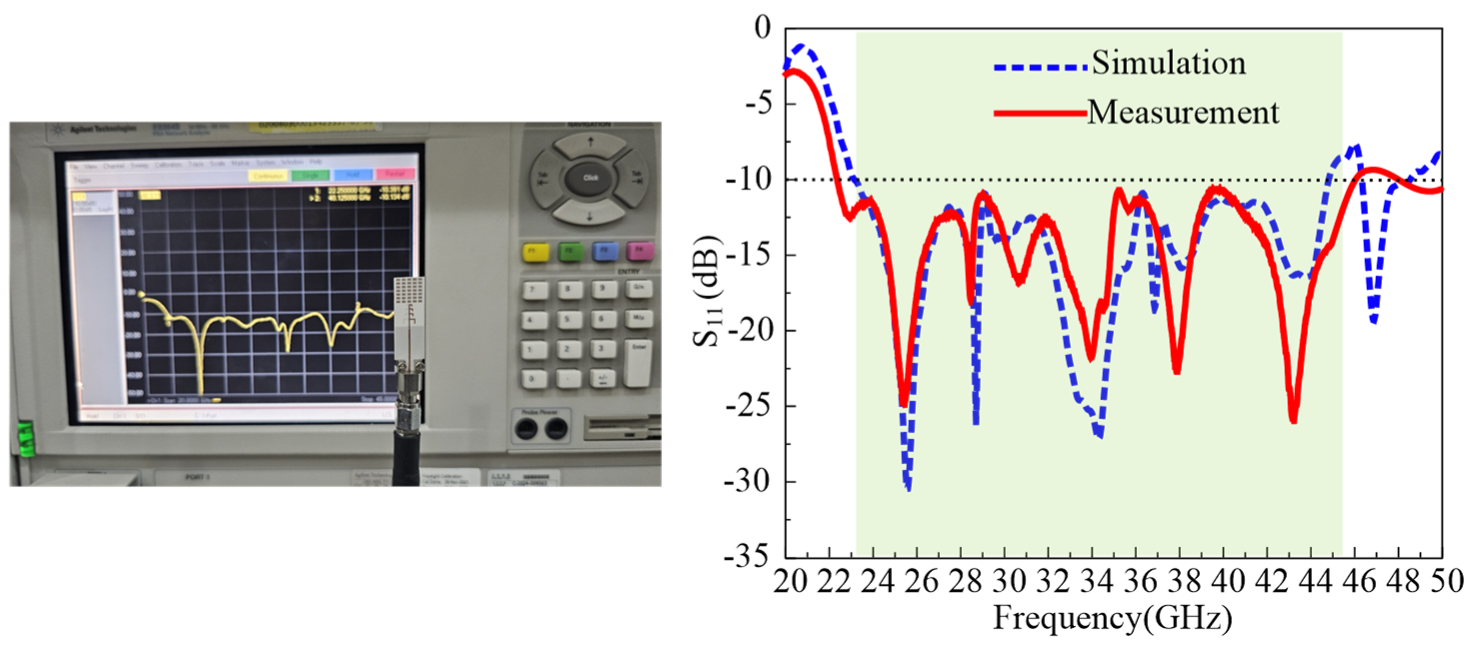
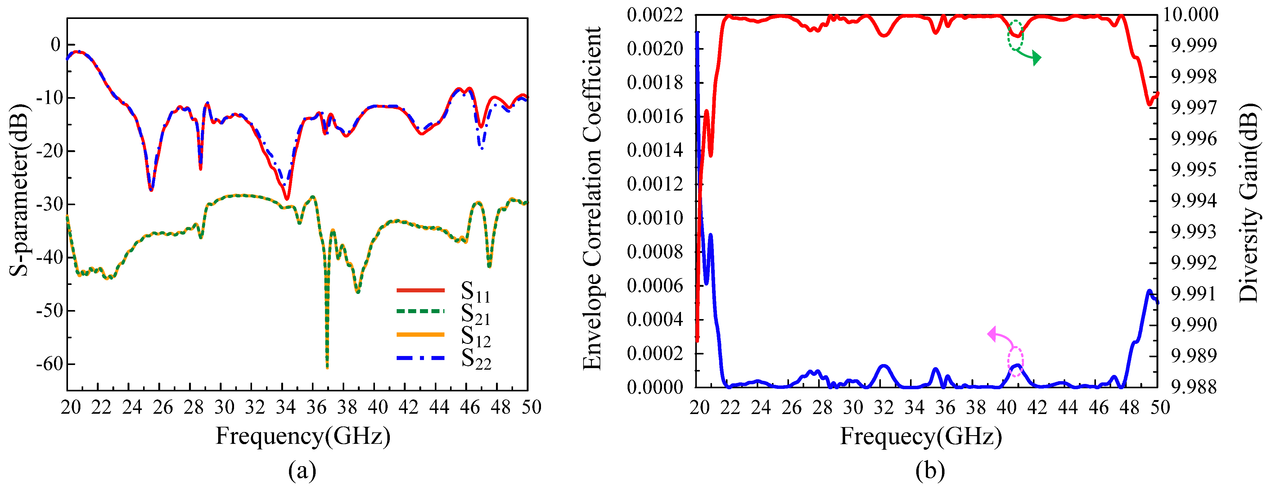
3.1. Reflection Coefficient

The reflection coefficient characteristic of the proposed metamaterial-based array dipole antenna is displayed in Figure 10. The proposed antenna offers a wide operating bandwidth from 23.1 GHz to 44.8 GHz. With an Agilent E8364B network analyzer in open-air, ambient settings, the S-parameters of the recommended antenna are measured. As seen in Figure 10, the slight difference between the simulation and measurement results is caused by cable/connector losses. A very broad impedance bandwidth of 63.92% (S11 ≤ −10 dB) is provided by the recommended antenna between 23 GHz and 45 GHz. The proposed bandwidth spans the whole n257, n258, and n259 frequency ranges as well as the n260 and n261 frequency bands for 5G NR millimeter-wave communication, which is recommended by the Third Generation Partnership Project (3GPP) and the ITU.

3.2. Radiation Pattern

Figure 11 illustrates the radiation pattern of the proposed metamaterial-based non-uniform dipole array antenna at different frequencies. While the 3D directivity pattern at 26 GHz, 28 GHz, and 38 GHz is presented in Figure 11a, the 2D polar radiation gain pattern is presented in Figure 11b. It can be seen from both simulated and measured radiation pattern graphs that the antenna offers an end-fire radiation characteristic. Due to the equipment losses during measurement, there is a slight mismatch between the simulated and measured results. The presented antenna yields a maximum gain of 11.21 dBi at 41 GHz, with 30.7° and 43.4° half-power-beam widths (HPBWs) at the E and H planes, respectively. The HPBW of the presented antenna at different frequencies is listed in Table 4, and the gain plot of the proposed antenna with respect to frequency is presented in the subsequent subsection, where the gain and radiation efficiency are explained. Additionally, the proposed antenna shows a side-lobe level less than −6 dB within the operating frequency band, which makes the proposed antenna suitable for the MIMO configuration for 5G technology.

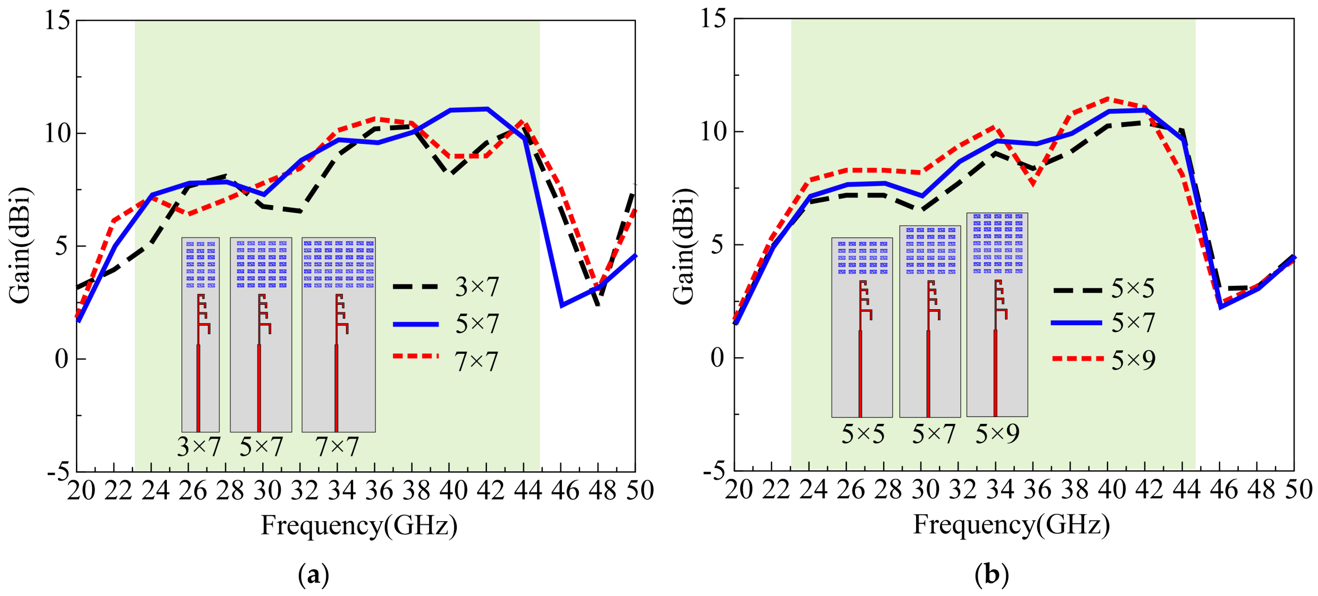
3.3. Gain and Radiation Efficiency

The gain and radiation characteristics of the proposed antenna are demonstrated in Figure 11, while the gain and the radiation efficiency are presented in Figure 12. It can be seen from Figure 12a that without the metamaterial structure, the antenna gain is quite low, especially at 28 GHz around 5 dBi, while the proposed metamaterial-integrated antenna offers a stable high gain of around 8 dBi within the operating frequency band, as presented in Figure 12b. Additionally, with the proposed metamaterial structure, the antenna provides a high maximum gain of 11.21 dBi at 41 GHz. The proposed metamaterial structure enhances the directivity of the antenna’s radiation, resulting in a gain increase of more than 3dBi compared to the dipole array alone. Due to antenna performance tradeoffs, the metamaterial structure shows a discontinuous result at higher frequencies (34–36 GHz), as depicted in Figure 6, which results in slightly lower radiation efficiency at that region, as can be seen in Figure 12. The proposed metamaterial structure configuration is finalized as it offers a significant gain enhancement. Overall, the proposed antenna also offers a good radiation efficiency of more than 64% within the operating frequency band, as shown in Figure 12b.

3.4. Performance Comparison

The performance comparison of the proposed metamaterial-based millimeter-wave antenna with similar available mm wave antennas from the literature is presented in Table 5. The performance is compared in terms of the type of antenna design, antenna volume, center frequency, bandwidth, radiation direction, peak gain, and substrate layers. Several antenna designs are reported in the literature to boost the performances of millimeter-wave antennas [17,18,19,20,21,22,23,24,25,26,27]. The reported antennas in [17,18,20,24,25,26] are designed on a single layer, while [10,25] offer wide operating bandwidths. However, all of these antennas suffer from very low antenna gain, especially the antennas in [24] and [25]. Similarly, the antennas in [21,22,23] and [27] suffer from the requirement of multi-substrate layers and offer narrow functional bandwidths. In contrast, our proposed metamaterial-based antenna offers a very high antenna gain of 11.21 dBi with a wide operating bandwidth of 63.92%. The performance parameters of the proposed antenna, high gain, wide bandwidth, and especially the end-fire radiation characteristics, make it a strong contender for wideband millimeter-wave 5G applications.

4. Limitations and Future Work Directions

This antenna provides broadband operation with stable gain and end-fire radiation. However, this work is limited to the exploration of a single-element design. For future communications, multiple-input multiple-output (MIMO) configurations are essential. To check the suitability of an MIMO configuration of the proposed metamaterial-integrated antenna, a two-port MIMO antenna is designed, as shown in Figure 13. Subsequently, the MIMO performance is studied. The distance between the two single antennas is kept as low as 3.8 mm.
The simulated reflection coefficient (Sii) and transmission coefficient (Sij) results of the designed two-port MIMO antenna are presented in Figure 14a. It can be seen that with the MIMO configuration, the antenna shows similar reflection coefficient characteristics to the proposed single-unit antenna. Moreover, the proposed antenna with the MIMO configuration offers very low mutual coupling (Sij) of less than −28 dB within the operating frequency band.
Other simulated MIMO performances metrics, such as the envelope correlation coefficient (ECC) and diversity gain (DG), derived from the S-parameters, are presented in Figure 14b. The MIMO configuration shows a very low ECC value, while the DG is close to the ideal value of 10 dB. Both the ECC and DG show good MIMO performance of the proposed antenna. Overall, the MIMO configuration of the proposed antenna shows an excellent performance, which makes it a viable candidate for 5G millimeter-wave MIMO technologies.

5. Conclusions

In this article, a high-gain millimeter-wave antenna with wideband characteristics is presented for 5G NR applications. The high-gain characteristic of the proposed metamaterial-integrated antenna is achieved by using the developed metamaterial structure. Initially, a non-uniform array dipole antenna is designed with a wide operating frequency band on an 8 mil thick Rogers RO4003C substrate. At this stage, the designed dipole antenna offers a peak gain of 8.02 dBi and a wide operating frequency. Afterwards, to boost the gain of the designed antenna, a metamaterial structure is proposed. The unit of the metamaterial structure is created and optimized in CST 2023 simulation software for a targeted frequency band from 22 GHz to 45 GHz. While the unit cell shows a promising performance for the targeted band, a repeated structure of the designed metamaterial unit cell is integrated with the designed dipole array in the direction of radiation. The proposed 5 × 7 metamaterial structure enhances the directivity of the antenna’s radiation, resulting in a high gain of more than 3 dBi compared to the dipole alone, which means that the gain of the initial antenna is doubled by using the proposed metamaterial. To validate the proposed method, a prototype of the presented antenna is fabricated and measured. The proposed antenna offers a wide operating bandwidth (23.1 GHz–44.8 GHz), covering the whole spectrum of 5G NR technology, including the n257, n258, n259, n260, and n261 bands. Moreover, the antenna offers a high antenna gain of 11.21 dBi with end-fire radiation characteristics. The proposed antenna offers a good radiation efficiency of more than 64% within the functional frequency band. Additionally, the proposed antenna shows a side-lobe level of less than −6 dB within the operating frequency band, which makes the proposed antenna suitable for the MIMO configuration in 5G technology. The overall performance of the presented metamaterial-integrated antenna makes it a viable option for 5G NR millimeter-wave applications.

Author Contributions

Conceptualization, D.C.; methodology, D.C., J.L., and M.A.S.; formal analysis, D.C., W.A.A., and J.L.; investigation, N.K., J.L., M.A.S., and Y.C.; data curation, D.C., Y.C., and W.A.A.; writing—original draft preparation, D.C.; writing—review and editing, M.A.S., W.A.A., and N.K.; visualization, D.C., Y.C., and J.L.; supervision, N.K.; project administration, N.K.; funding acquisition, N.K. All authors have read and agreed to the published version of the manuscript.

Funding

This work was supported by an Institute of Information & Communications Technology Planning & Evaluation (IITP) grant funded by the Korean government (MSIT) (No. 2022-0-01031, Development of measured EMF big data analysis and management platform).

Institutional Review Board Statement

Not applicable.

Informed Consent Statement

Not applicable.

Data Availability Statement

The original contributions presented in this study are included in the article; further inquiries can be directed to the corresponding author.

Conflicts of Interest

The authors declare no conflicts of interest.

References

  1. Agiwal, M.; Roy, A.; Saxena, N. Next Generation 5G Wireless Networks: A Comprehensive Survey. IEEE Commun. Surv. Tutor. 2016, 18, 1617–1655. [Google Scholar] [CrossRef]
  2. Yu, X.; Li, J.; Hu, J.; Yao, Y.; Li, J.; Yan, S. Low-Profile Dual-Polarized Antenna Integrated with Horn and Vivaldi Antenna in Millimeter-Wave Band. Appl. Sci. 2023, 13, 9627. [Google Scholar] [CrossRef]
  3. Zhang, Y.; Luo, Y.; Ji, R. Millimeter-Wave High-Gain Dual-Polarized Flat Luneburg Lens Antenna with Reflection Cancellation. Appl. Sci. 2023, 13, 6468. [Google Scholar] [CrossRef]
  4. Azari, A.; Skrivervik, A.; Aliakbarian, H.; Sadeghzadeh, R.A. A Super Wideband Dual-Polarized Vivaldi Antenna for 5G mmWave Applications. IEEE Access 2023, 11, 80761–80768. [Google Scholar] [CrossRef]
  5. Zhu, Y.; Chen, K.; Tang, S.Y.; Yu, C.; Hong, W. Ultrawideband Strip-Loaded Slotted Circular Patch Antenna Array for Millimeter-Wave Applications. IEEE Antennas Wireless Propag. Lett. 2023, 22, 2230–2234. [Google Scholar] [CrossRef]
  6. Hussain, N.; Kim, N. Integrated Microwave and mm-Wave MIMO Antenna Module with 360 Pattern Diversity for 5G Internet of Things. IEEE Internet Things J. 2022, 9, 24777–24789. [Google Scholar] [CrossRef]
  7. International Telecommunication Union (ITU). Spectrum Allocation for 5G International Framework. Available online: https://www.itu.int/en/ITU-D/Regional-Presence/Europe/Documents/Events/2019/RED-2019/presentation/4.5-%D0%A0%D0%B5%D1%81%D1%82%D1%80%D0%B5%D0%BF%D0%BE.pdf (accessed on 16 April 2024).
  8. Abdou, T.S.; Saad, R.; Khamas, S.K. A Circularly Polarized mmWave Dielectric-Resonator-Antenna Array for Off-Body Communications. Appl. Sci. 2023, 13, 2002. [Google Scholar] [CrossRef]
  9. Lo, J.J.; Chen, Z.N. Design of a Broadband Millimeter-Wave Array Antenna for 5G Applications. IEEE Antennas Wireless Propag. Lett. 2022, 22, 1030–1034. [Google Scholar]
  10. Sufian, M.A.; Hussain, N.; Choi, D.; Lee, S.M.; Gil, S.K.; Kim, N. High Gain Quasi-Omnidirectional Dipole Array Fed by Radial Power Divider for Millimeter-Wave IoT Sensing. Sci. Rep. 2024, 14, 16279. [Google Scholar] [CrossRef]
  11. Zhu, Y.; Deng, C. Wideband Dual-Polarized Endfire Phased Array Antenna with Small Ground Clearance for 5G mmWave Mobile Terminals. IEEE Trans. Antennas Propag. 2023, 71, 5469–5474. [Google Scholar] [CrossRef]
  12. International Telecommunication Union (ITU). ETSI & 3GPP 5G Standardization toward IMT-2020 Radio Spectrum and Interface. Available online: https://www.itu.int/en/ITU-D/Regional-Presence/Europe/Documents/Events/2018/5GHungary/S3%20Mihaljevic%205G%20Standard.pdf (accessed on 11 March 2024).
  13. Sheik, J.A. Intelligent Signal Processing and RF Energy Harvesting for State of Art 5G and B5G Networks; Springer Nature: Berlin, Germany, 2024; pp. 97–112. [Google Scholar]
  14. Oh, J.; Kim, B.; Yoon, S.; Kim, K.; Sung, E.J.; Oh, J. High-Gain Millimeter-Wave Antenna-in-Display Using Non-Optical Space for 5G Smartphones. IEEE Trans. Antennas Propag. 2022, 71, 1458–1468. [Google Scholar] [CrossRef]
  15. Sufian, M.A.; Hussain, N.; Kim, N. Quasi-Binomial Series-Fed Array for Performance Improvement of Millimeter-Wave Antenna for 5G MIMO Applications. Eng. Sci. Technol. Int. J. 2023, 47, 101548. [Google Scholar] [CrossRef]
  16. Wen, L.; Yu, Z.; Zhu, L.; Zhou, J. High-Gain Dual-Band Resonant Cavity Antenna for 5G Millimeter-Wave Communications. IEEE Antennas Wireless Propag. Lett. 2021, 20, 1878–1882. [Google Scholar] [CrossRef]
  17. Hwang, I.J.; Ahn, B.; Chae, S.C.; Yu, J.W.; Lee, W.W. Quasi-Yagi Antenna Array with Modified Folded Dipole Driver for mmWave 5G Cellular Devices. IEEE Antennas Wireless Propag. Lett. 2019, 18, 971–975. [Google Scholar] [CrossRef]
  18. Kimionis, J.; Georgiadis, A.; Daskalakis, S.N.; Tentzeris, M.M. A Printed Millimetre-Wave Modulator and Antenna Array for Backscatter Communications at Gigabit Data Rates. Nat. Electron. 2021, 4, 439–446. [Google Scholar] [CrossRef]
  19. Attia, H.; Abdelghani, M.L.; Denidni, T.A. Wideband and High-Gain Millimeter-Wave Antenna Based on FSS Fabry–Perot Cavity. IEEE Trans. Antennas Propag. 2017, 65, 5589–5594. [Google Scholar] [CrossRef]
  20. Zhai, G.; Cheng, Y.; Yin, Q.; Zhu, S.; Gao, J. Gain Enhancement of Printed Log-Periodic Dipole Array Antenna Using Director Cell. IEEE Trans. Antennas Propag. 2014, 62, 5915–5919. [Google Scholar] [CrossRef]
  21. Kim, J.; Lee, H.L. High Gain Planar Segmented Antenna for mmWave Phased Array Applications. IEEE Trans. Antennas Propag. 2022, 70, 5918–5922. [Google Scholar] [CrossRef]
  22. Nkimbeng, C.H.S.; Wang, H.; Byun, G.; Park, Y.B.; Park, I. Non-Uniform Metasurface-Integrated Circularly Polarized End-Fire Dipole Array Antenna. J. Electromagn. Eng. Sci. 2023, 23, 109–121. [Google Scholar] [CrossRef]
  23. Wu, Q.; Hirokawa, J.; Yin, J.; Yu, C.; Wang, H.; Hong, W. Millimeter-Wave Multibeam Endfire Dual-Circularly Polarized Antenna Array for 5G Wireless Applications. IEEE Trans. Antennas Propag. 2018, 66, 4930–4935. [Google Scholar] [CrossRef]
  24. Chen, H.; Shao, Y.; Zhang, Y.; Zhang, C.; Zhang, Z. A Low-Profile Broadband Circularly Polarized mmWave Antenna with Special-Shaped Ring Slot. IEEE Antennas Wireless Propag. Lett. 2019, 18, 1492–1496. [Google Scholar] [CrossRef]
  25. Munir, M.E.; Nasralla, M.M.; Esmail, M.A. Four Port Tri-Circular Ring MIMO Antenna with Wide-Band Characteristics for Future 5G and mmWave Applications. Heliyon 2024, 10, e28714. [Google Scholar] [CrossRef] [PubMed]
  26. Ozpinar, H.; Aksimsek, S.; Tokan, N.T. A Novel Compact, Broadband, High Gain Millimeter-Wave Antenna for 5G Beam Steering Applications. IEEE Trans. Veh. Technol. 2020, 69, 2389–2397. [Google Scholar] [CrossRef]
  27. Jeong, M.J.; Hussain, N.; Park, J.W.; Park, S.G.; Rhee, S.Y.; Kim, N. Millimeter-Wave Microstrip Patch Antenna Using Vertically Coupled Split Ring Metaplate for Gain Enhancement. Microw. Opt. Technol. Lett. 2019, 61, 2360–2365. [Google Scholar] [CrossRef]
  28. Esmail, B.A.; Koziel, S. Design and Optimization of Metamaterial-Based 5G Millimeter Wave Antenna for Gain Enhancement. IEEE Trans. Circuits Syst. II Express Briefs 2023, 70, 3348–3352. [Google Scholar] [CrossRef]
  29. Saleh, C.M.; Almajali, E.; Jarndal, A.; Yousaf, J.; Alja’Afreh, S.S.; Amaya, R.E. Wideband 5G Antenna Gain Enhancement Using a Compact Single-Layer Millimeter Wave Metamaterial Lens. IEEE Access 2023, 11, 14928–14942. [Google Scholar] [CrossRef]
  30. Chen, X.; Grzegorczyk, T.M.; Wu, B.I.; Pacheco, J., Jr.; Kong, J.A. Robust Method to Retrieve the Constitutive Effective Parameters of Metamaterials. Phys. Rev. E Stat. Nonlinear Soft Matter Phys. 2004, 70, 016608. [Google Scholar] [CrossRef]
  31. Chen, L.; Lei, Z.; Yang, R.; Fan, J.; Shi, X. A Broadband Artificial Material for Gain Enhancement of Antipodal Tapered Slot Antenna. IEEE Trans. Antennas Propag. 2014, 63, 395–400. [Google Scholar] [CrossRef]
  32. Esmail, B.A.; Koziel, S.; Pietrenko-Dabrowska, A.; Isleifson, D. Wideband High-Gain Low-Profile Series-Fed Antenna Integrated with Optimized Metamaterials for 5G Millimeter Wave Applications. Sci. Rep. 2024, 14, 185. [Google Scholar] [CrossRef]
  33. Khoutar, F.Z.; Nayat-Ali, O.; Aznabet, M.; El Mrabet, O. A Multifunctional Patch Antenna Loaded with Near Zero Index Refraction Metamaterial. Prog. Electromagn. Res. M 2022, 114, 127–137. [Google Scholar] [CrossRef]
  34. Smith, D.R.; Vier, D.C.; Koschny, T.; Soukoulis, C.M. Electromagnetic Parameter Retrieval from Inhomogeneous Metamaterials. Phys. Rev. E Stat. Nonlinear Soft Matter Phys. 2005, 71, 036617. [Google Scholar] [CrossRef] [PubMed]
  35. Li, D.; Szabó, Z.; Qing, X.; Li, E.P.; Chen, Z.N. A High Gain Antenna with an Optimized Metamaterial Inspired Superstrate. IEEE Trans. Antennas Propag. 2012, 60, 6018–6023. [Google Scholar] [CrossRef]
  36. Patel, S.K.; Shah, K.H.; Kosta, Y.P. Frequency-Reconfigurable and High-Gain Metamaterial Microstrip-Radiating Structure. Waves Random Complex Media 2019, 29, 523–539. [Google Scholar] [CrossRef]
  37. EMTI Homepage. Available online: http://emti.or.kr/ (accessed on 12 December 2021).
Figure 1. Representation of mm wave device connection in 5G-NR environment.
Applsci 14 09138 g001
Figure 2. The dipole array antenna: (a) a view of the individual sides and (b) a partially transparent view of the substrate.
Applsci 14 09138 g002
Figure 3. The performance characteristics of the dipole array antenna: (a) the reflection coefficient, and (b) the gain and 3D directivity at 28 GHz and 38 GHz.
Applsci 14 09138 g003
Figure 4. The surface current distribution of the dipole array at different operating frequencies.
Applsci 14 09138 g004
Figure 5. Parametric analysis of the dipole array antenna for different parameters: (a) for P1 and (b) for P4.
Applsci 14 09138 g005
Figure 6. The properties of the metamaterial unit cell: (a) a schematic diagram with the design parameters, (b) the gain enhancement mechanism, (c) the characteristic response, and (d) the material properties.
Applsci 14 09138 g006
Figure 7. The geometry and design parameters of the proposed metamaterial-integrated dipole array antenna.
Applsci 14 09138 g007
Figure 8. The gain response of the dipole antenna varies with different numbers of metamaterial cells (a) horizontally and (b) vertically.
Applsci 14 09138 g008
Figure 9. Photographs of the presented metamaterial-integrated dipole array antenna: (a) the fabricated prototype and (b) the radiation characterization measurement setup.
Applsci 14 09138 g009aApplsci 14 09138 g009b
Figure 10. The reflection coefficient of the metamaterial-integrated dipole array antenna.
Applsci 14 09138 g010
Figure 11. The radiation pattern of the developed metamaterial-integrated dipole array antenna: (a) simulated 3D directivity at different frequencies and (b) 2D polar radiation pattern with gain scale.
Applsci 14 09138 g011
Figure 12. Simulated and measured gain, and radiation efficiency performance: (a) antenna without metamaterial structure and (b) antenna with metamaterial structure.
Applsci 14 09138 g012
Figure 13. The 2-port MIMO configuration of the proposed metamaterial-integrated non-uniform dipole array.
Applsci 14 09138 g013
Figure 14. The results of the MIMO configuration of the proposed antenna: (a) S-parameters and (b) the ECC and DG.
Applsci 14 09138 g014
Table 1. The design parameters and the optimal values of the dipole array antenna.
ParameterValue (mm)ParameterValue (mm)ParameterValue (mm)ParameterValue (mm)
SL32f20.3h31.3p40.65
Sw10L3.2h41.1q11.4
FL14.4H8.3p11.8q20.7
GL15.3h13.2p21.17q30.6
f10.5h21.5p31q40.45
Table 2. The design parameters and the optimal values of the metamaterial unit cell.
ParameterValue (mm)ParameterValue (mm)ParameterValue (mm)
u11.08u30.495u50.27
u20.252u40.18u60.09
Table 3. Gain and frequency responses for various configurations of metamaterials.
Metamaterial
Arrangement
Gain (dBi)Frequency Response (GHz)Metamaterial
Arrangement
Gain (dBi)Frequency Response (GHz)
Min.Max.Min.Max.
3 × 75.1210.323.5–40.15 × 56.510.3923.3–40.9
5 × 77.2811.2123.1–44.85 × 77.2811.2123.1–44.8
7 × 76.410.6323.5–40.65 × 97.7211.4323.2–36.4
36.5–39.6
40.7–44.8
Table 4. The HPBW of the proposed antenna at different operating frequencies.
Freq.
(GHz)
HPBW (°)Freq.
(GHz)
HPBW (°)Freq.
(GHz)
HPBW (°)Freq.
(GHz)
HPBW (°)
E PlaneH PlaneE PlaneH PlaneE PlaneH PlaneE PlaneH Plane
227387.22854.174.43442.447.64031.645
2454.675.93060.372.83638.345.24228.142.9
2651.776.83250.759.13835.250.24424.943.7
Table 5. Performance comparison of proposed metamaterial-based high-gain mm wave antenna.
Refs.Antenna TypeTotal Antenna Size
(λ × λ × λ)
Center Freq. (GHz)BW (%)Radiation DirectionPeak Gain (dBi)Substrate
Layers
[17]Quasi-Yagi5.88 × 4.22 × 0.07289.64Broadside9.8Single
[18]Planar series-array antenna6.07 × 1.74 × 0.0152615.38Broadside10Single
[20]Log-periodic dipole array + director cell2.49 × 1.51 × 0.0530.558.46End-fire10.95Single
[21]Multi-layer planar segmented antenna (PSA)1.213 × 1.213 × 0.1132821.6Broadside11.5Double
[22]Metasurface-integrated dipole2.76 × 2.76 × 2.7830.521.5End-fire11Single + 2 layers of metasurface
[23]Dielectric-loaded stepped slot antenna + substrate-integrated waveguide (SIW)1.31 × 0.75 × 0.3937.523.6End-fire7.2Double
[24]Planar antenna with defective ground + metallic vias2.8 × 1.4 × 0.032829.82Omnidirectional6.49Single
[25]Ring-shaped patch with slotted ground0.77 × 1.21 × 0.0283342.4Omnidirectional5.36Single
[26]Clover antenna array3.6 × 0.347 × 0.052632.6Broadside9Single
[27]Printed antenna + Metamaterial Layer1.68 × 2.05 × 1.6527.965.9Broadside11.94Double + 1 foam layer
This workNon-uniform dipole array with metamaterial2.98 × 0.93 × 0.01933.9563.92End-fire11.21Single
Disclaimer/Publisher’s Note: The statements, opinions and data contained in all publications are solely those of the individual author(s) and contributor(s) and not of MDPI and/or the editor(s). MDPI and/or the editor(s) disclaim responsibility for any injury to people or property resulting from any ideas, methods, instructions or products referred to in the content.

