
Dynamic Modeling and Vibration Characteristic Analysis of Fiber Woven Composite Shaft–Disk Rotor with Weight-Reducing Holes


Abstract
1. Introduction
2. Dynamic Modeling Process of the Fiber Woven Composite Shaft–Disk Rotor
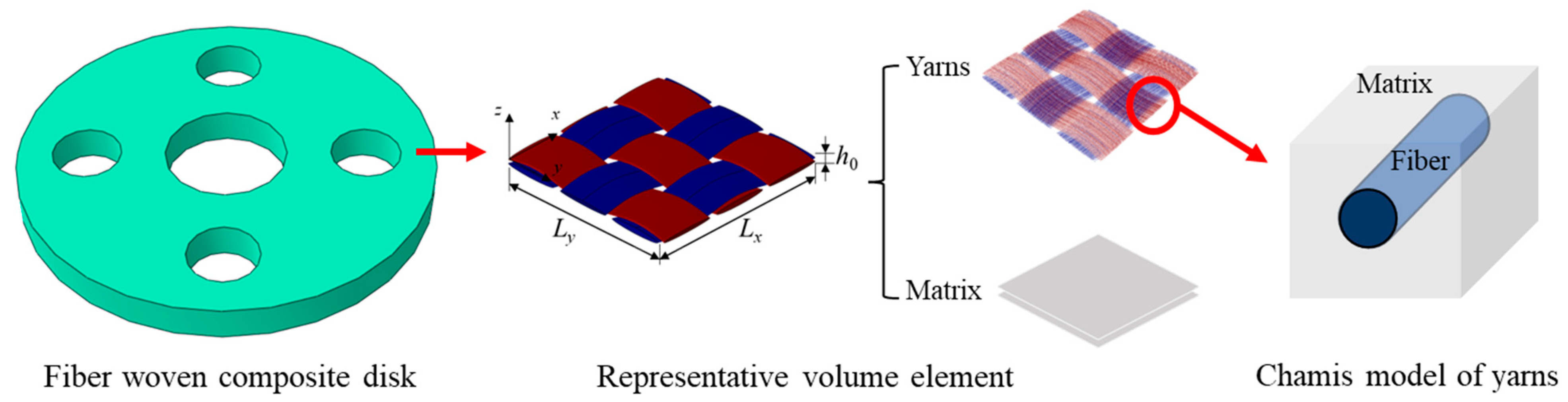
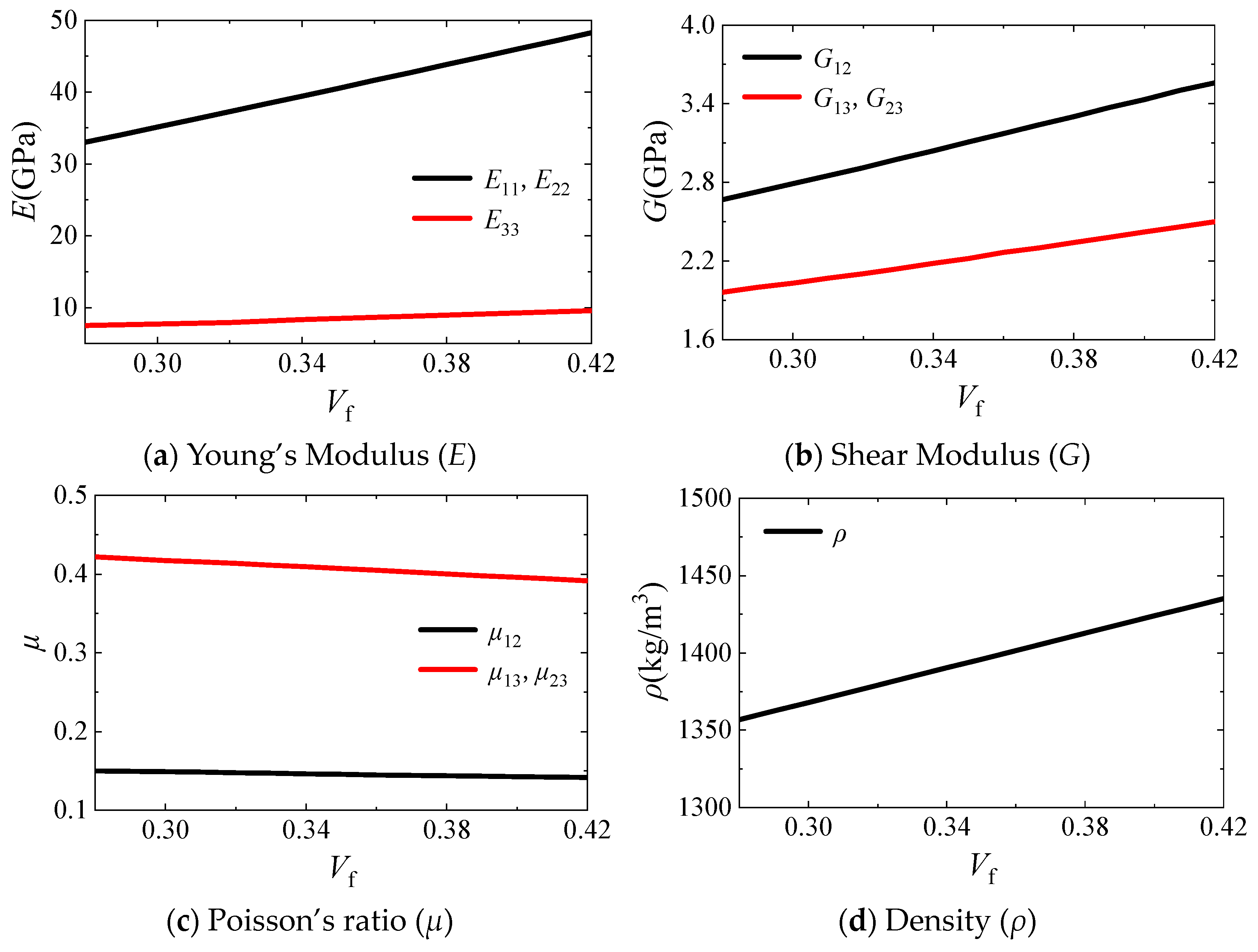
2.1. Application of Fiber Woven Composite
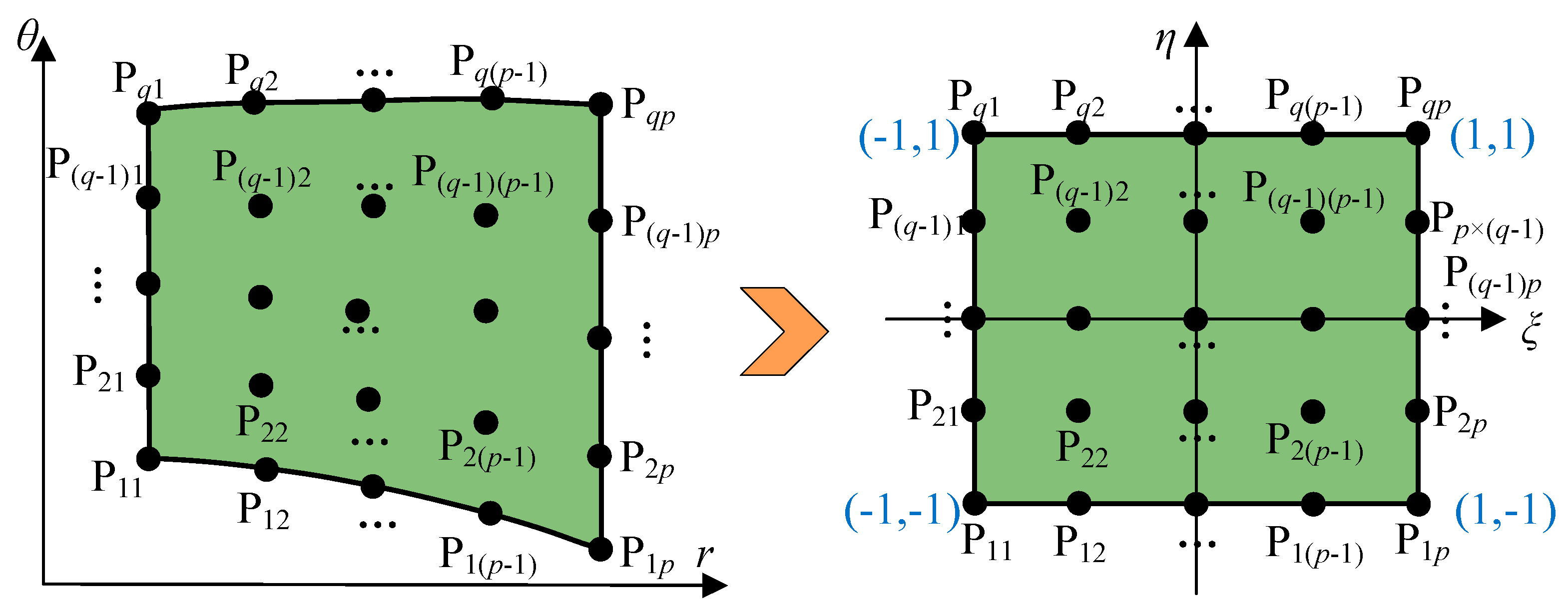
2.2. Domain Decomposition and Coordinate Mapping Technique for Perforated Webs
2.3. Energy Derivation of System Structure Units
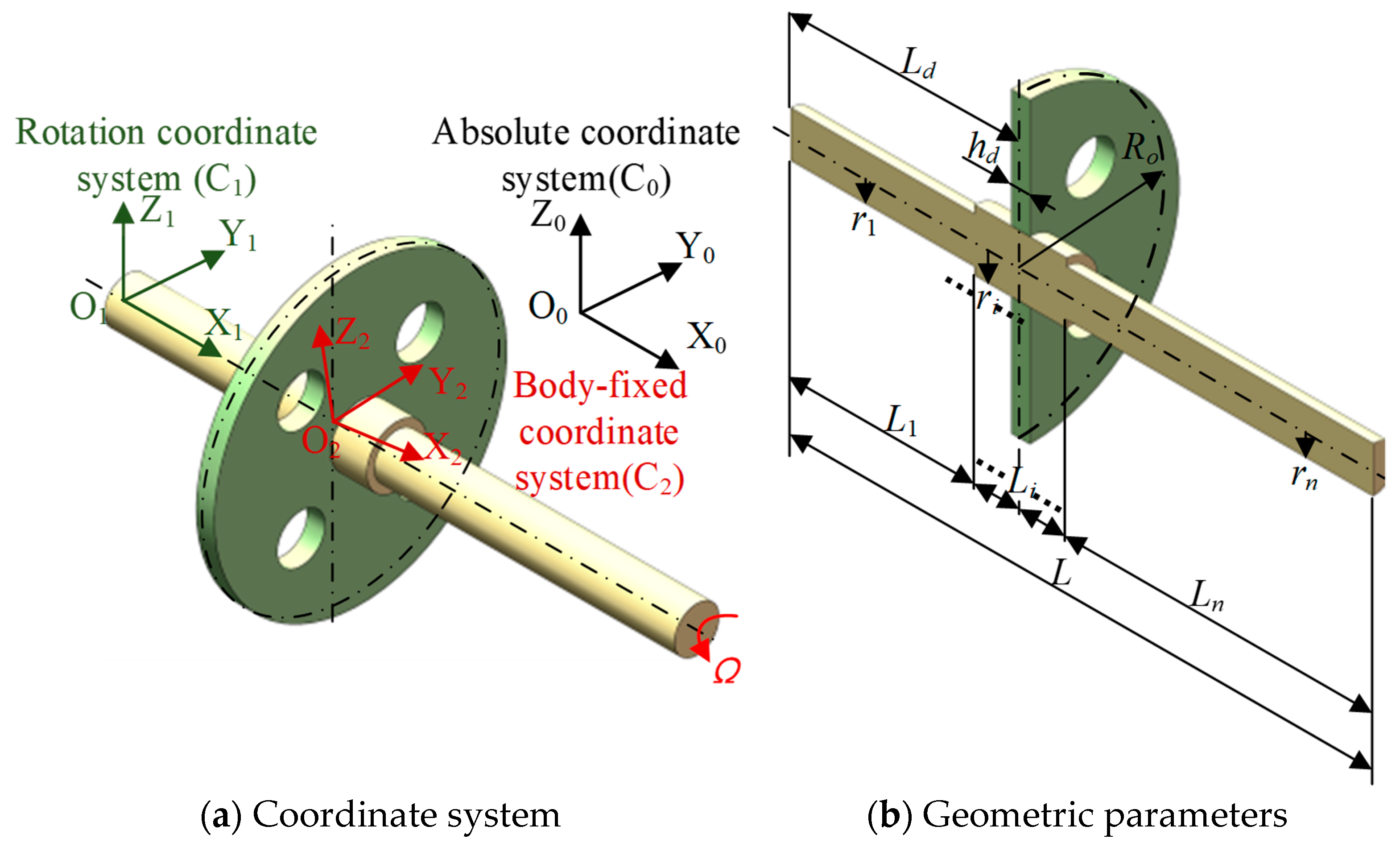
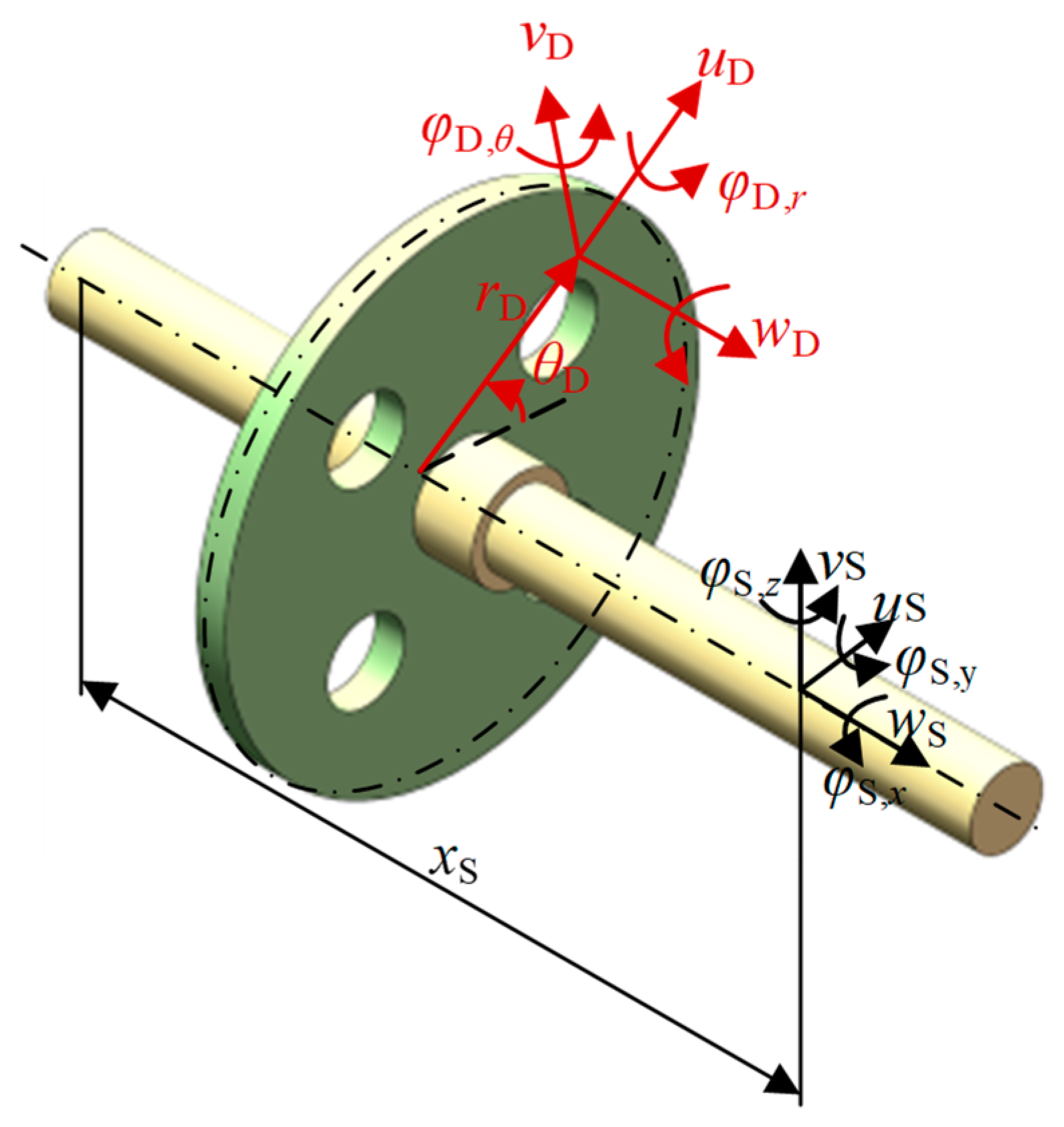
2.3.1. Potential and Kinetic Energy of the Rotating Shaft Units
2.3.2. Potential and Kinetic Energy of the Disk Units
2.4. Overall Model of the Rotor System
3. Numerical Analysis
3.1. Convergence Study
3.2. Verification
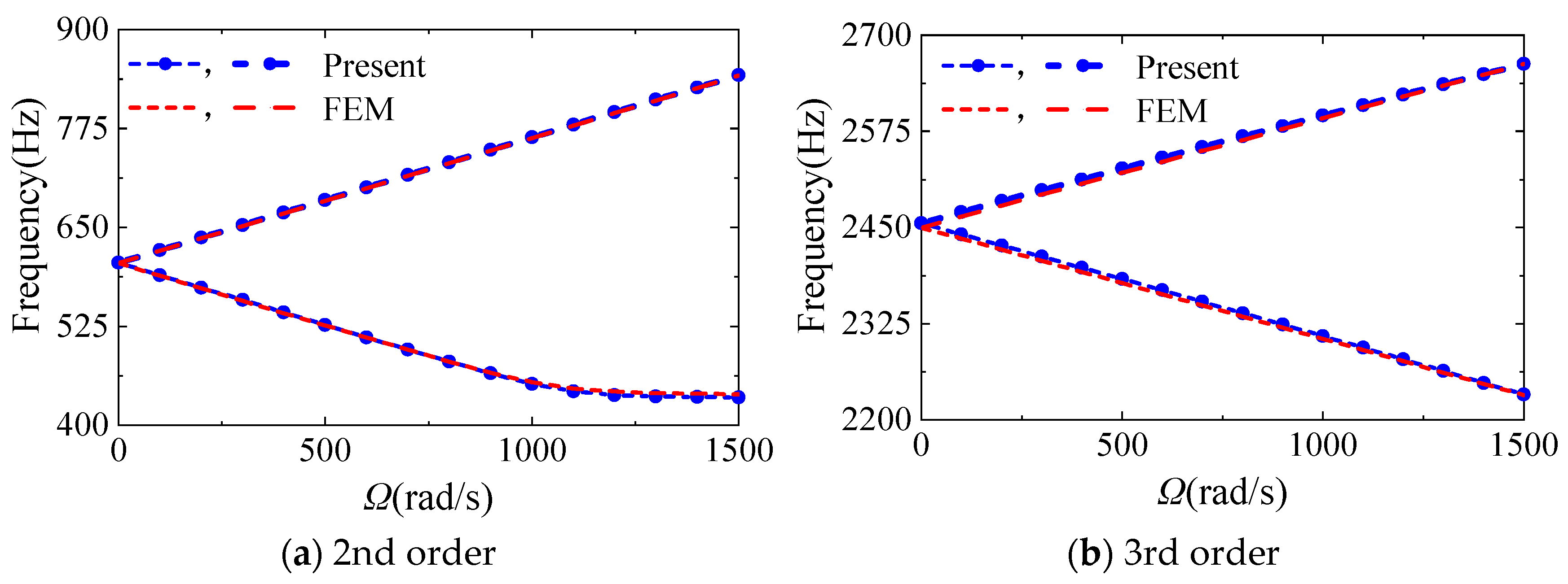
3.2.1. Validation of Literature and FEM
3.2.2. Experimental Verification
- (1)
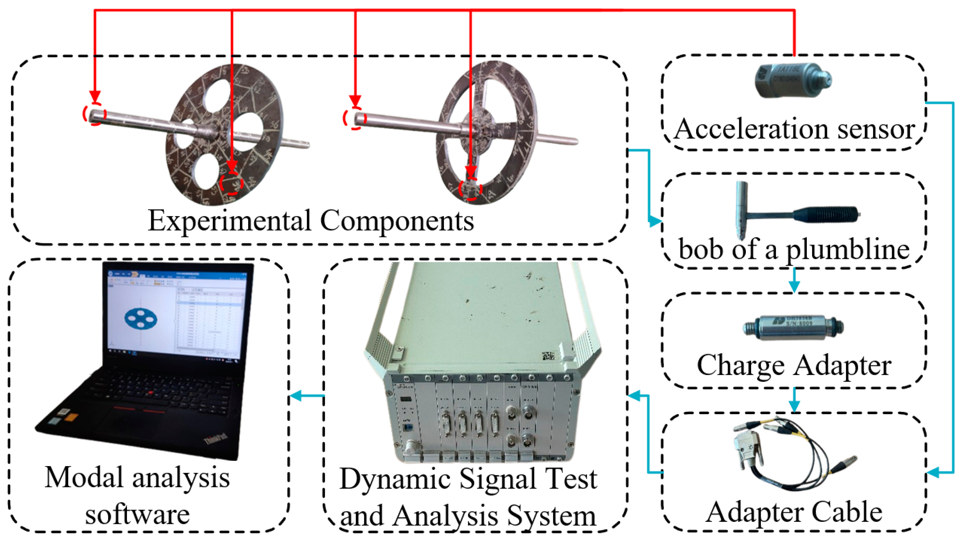
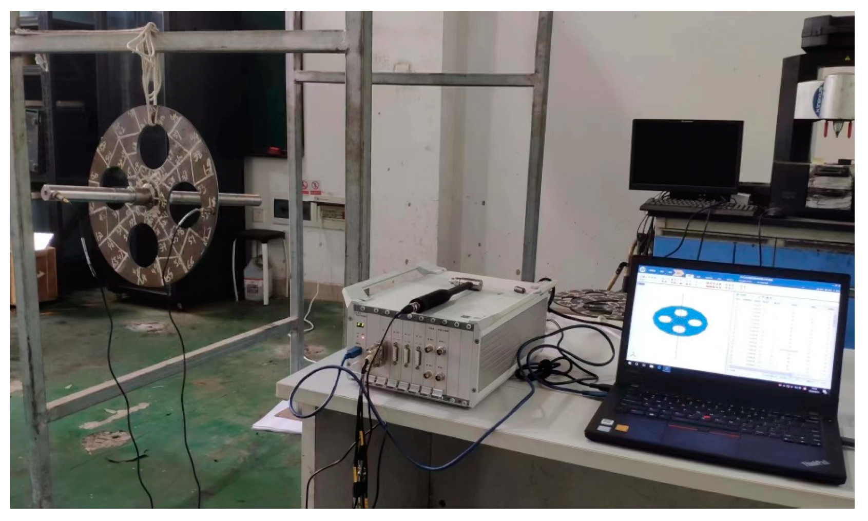
- Experimental pre-processing. The experimental parts are processed, and according to the size of the experimental parts in the modal analysis software, the model is drawn and the measurement point numbering is completed. Then, the corresponding measurement points are drawn. The experimental parts are set as the free boundary, and the elastic rope suspension is used to simulate the boundary conditions. The simulation of the experimental parts is completed and the nodes with large deformation in each order of the modal state are selected as the response test points in order to paste the sensor during the experiment.
- (2)
- Experimental measurement. The experiment of disk structure adopts the method of single-point vibration pickup; the experiment of shaft–disk structure adopts the method of single-point excitation and multi-point response, so the modal test of the disk only needs to place a single acceleration sensor on the response test point, while the shaft–disk system needs to select a measurement point on the shaft and the disk and paste acceleration sensors. Afterwards, the device connection is completed and the device parameters are debugged. Finally, the force hammer is used to tap each measurement point in turn to obtain and store the response data.
- (3)
- Post-experiment processing. After completing the experiment, the obtained data are processed through the modal analysis software, the intrinsic frequency is calculated, and the modal vibration pattern is plotted.
3.3. Parametric Studies
4. Conclusions
- (1)
- The existing fiber woven composite rotor model has good convergence and accuracy, while the disk’s mass is reduced by 82.6% and the first-order coupled natural frequency is slightly reduced compared to the steel rotor.
- (2)
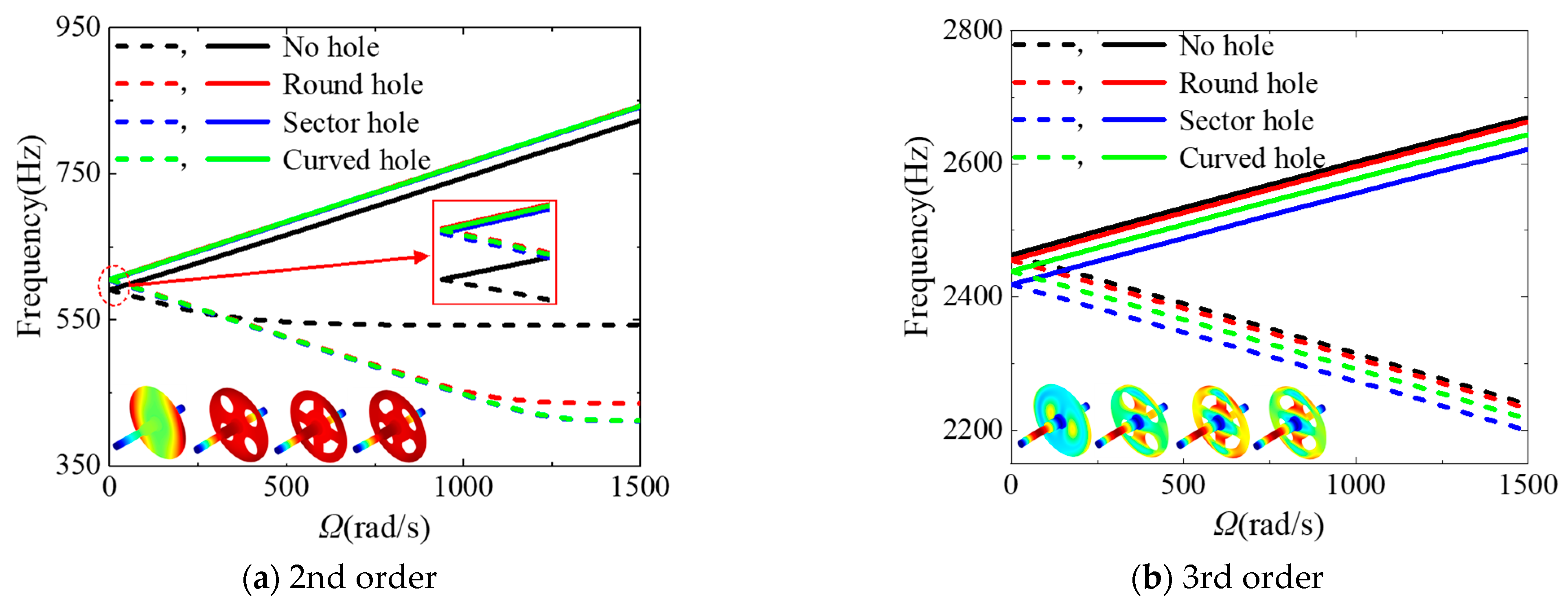
- The 1st and 4th coupled modes of the rotor are dominated by the displacement of the disk, while the 2nd- and 3rd-order modes contain the deformation of each structure, in which the disk displacement in the 2nd mode is mainly determined by the displacement of the coupling point on the shaft.
- (3)
- The hole type on the disk directly affect the 3rd critical speed of the rotor, which is ranked in descending order as “no hole > round hole > curved hole > sector hole”.
- (4)
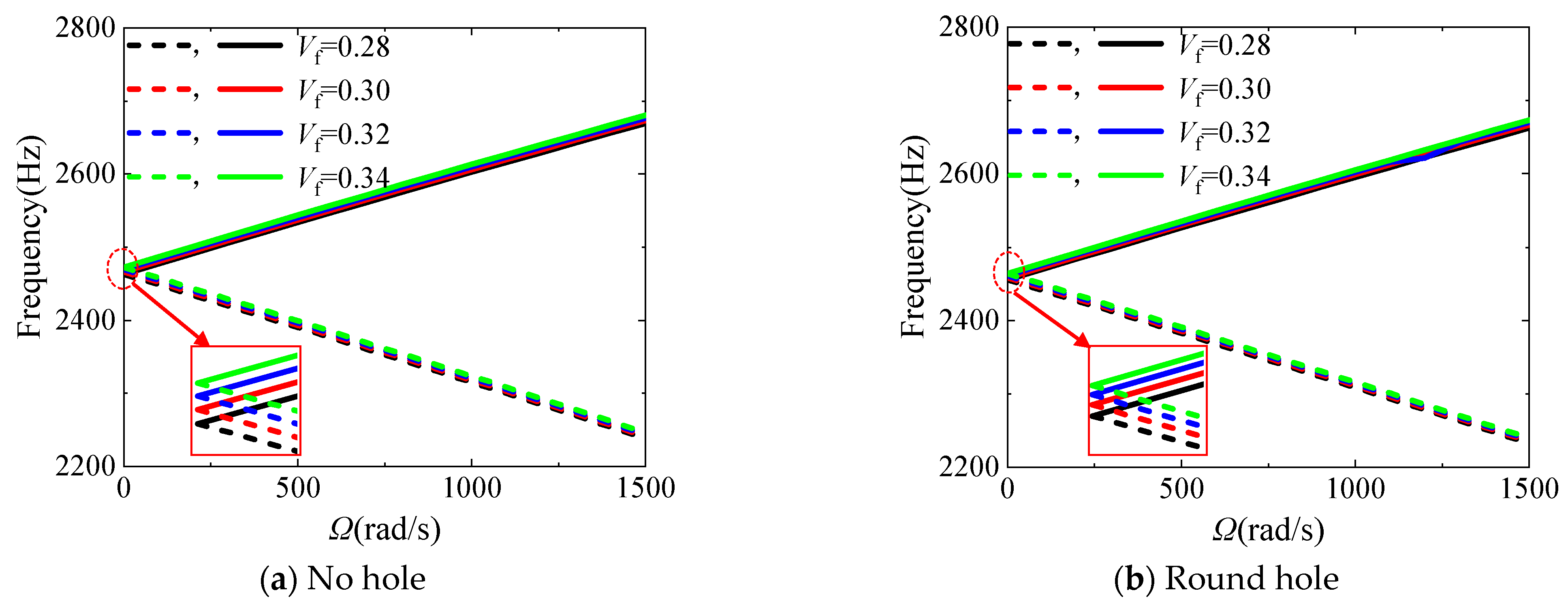
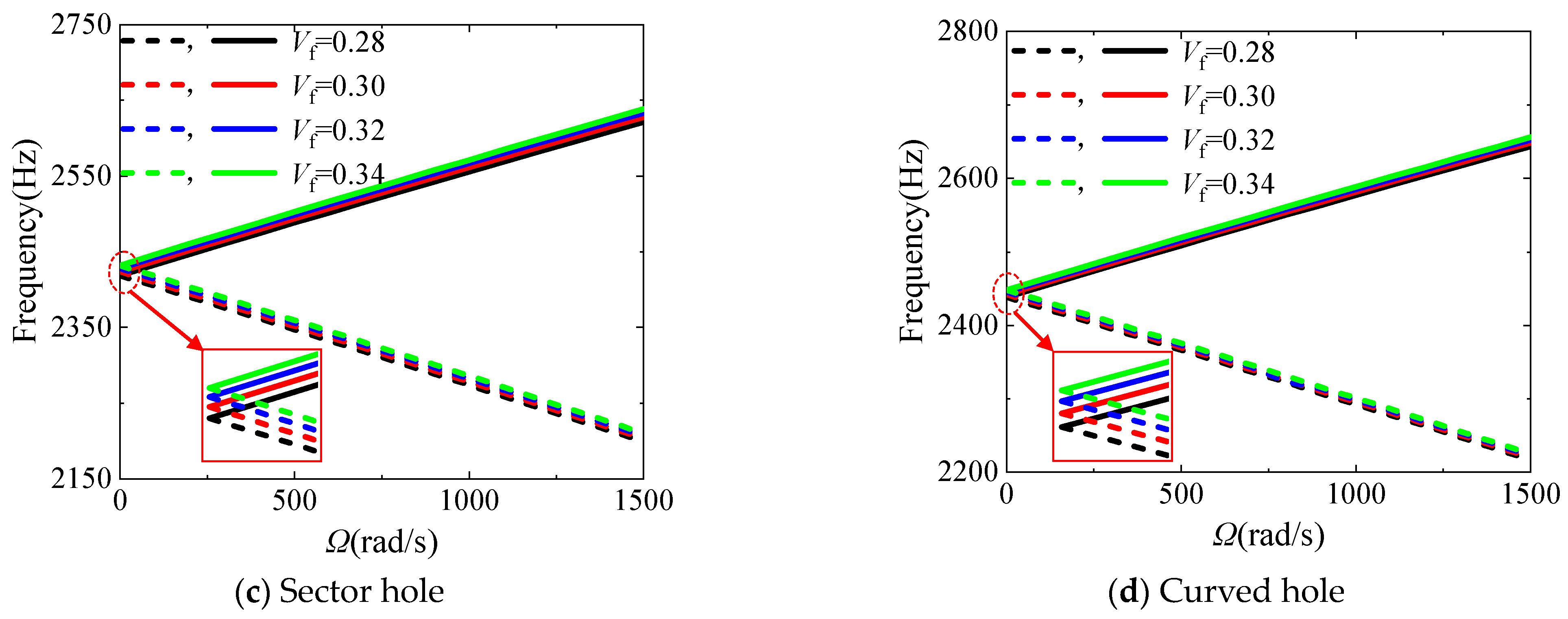
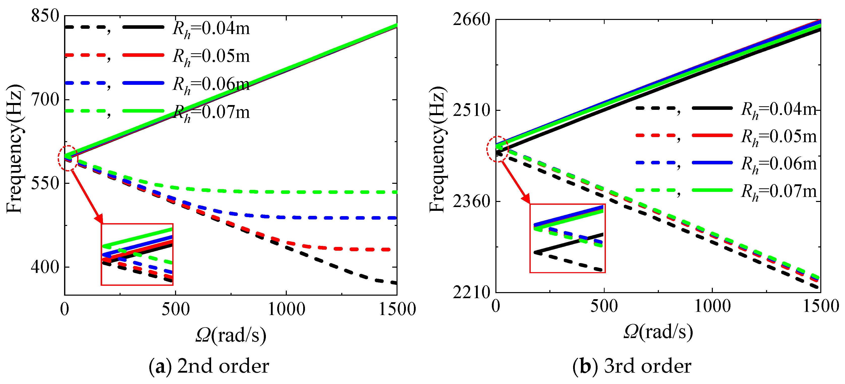
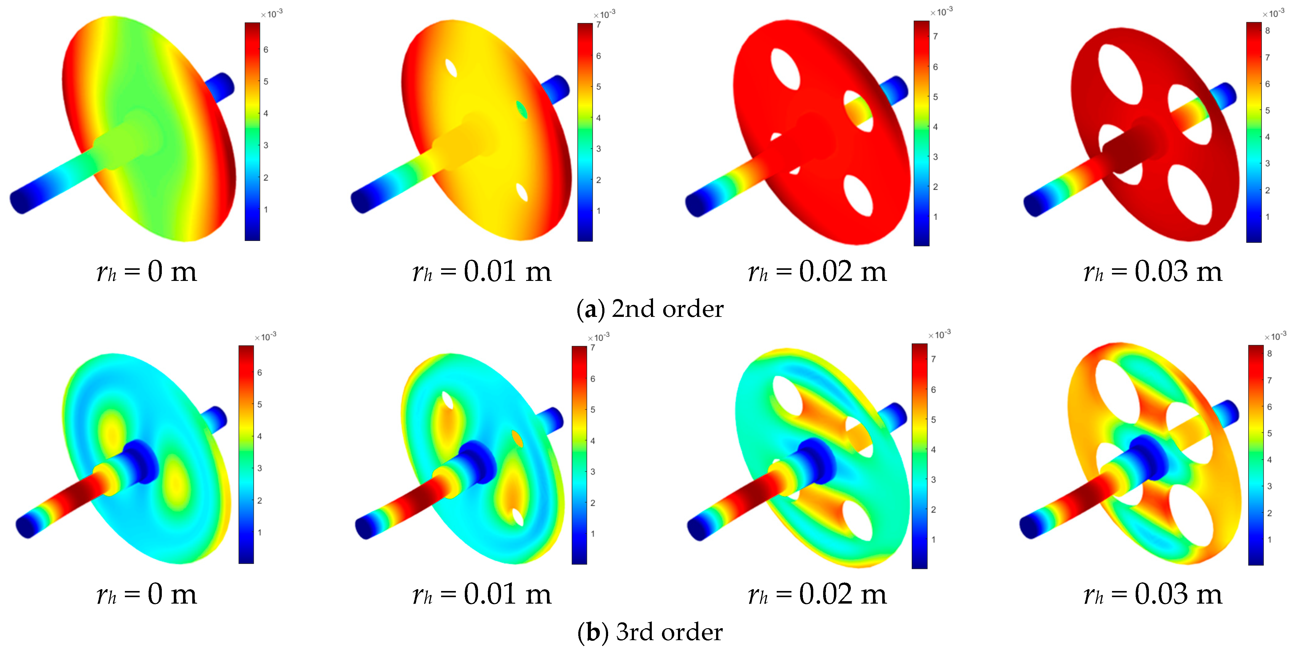
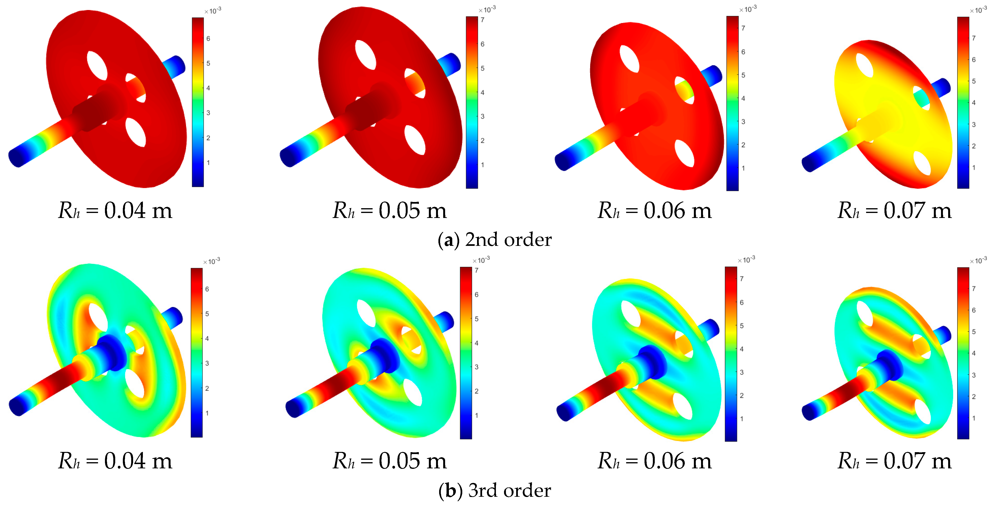
- Taking the rotor with circular holes as an example, the increase in the total fiber volume fraction Vf, the hole eccentricity Rh and the hole number N, as well as the decrease in the hole radius rh, all enhance the 3rd coupled natural frequency and the critical speed of the fiver woven composite rotor system. Among them, the effect of the hole radius is the most significant.
Author Contributions
Funding
Institutional Review Board Statement
Informed Consent Statement
Data Availability Statement
Acknowledgments
Conflicts of Interest
References
- Zhang, Y.; Li, H.; Liu, X.; Chen, Y.; Qin, C.; Fang, D. Prediction of mechanical properties of 3D tubular braided composites at different temperatures using a multi-scale modeling framework based on micro-CT. Compos. Sci. Technol. 2024, 245, 110349. [Google Scholar] [CrossRef]
- Huang, C.; Norton, M.; Joosten, M.W. Investigating the tensile properties of 3D printed semi-woven intraply hybrid composites reinforced with carbon/glass continuous fibres. Compos. Part A Appl. Sci. Manuf. 2024, 177, 107924. [Google Scholar] [CrossRef]
- Kumar, Y.; Rezasefat, M.; Amico, S.C.; Manes, A.; Dolez, P.I.; Hogan, J.D. Comparison of two progressive damage models for predicting low-velocity impact behavior of woven composites. Thin-Walled Struct. 2024, 197, 111611. [Google Scholar] [CrossRef]
- Grotz, L.; Kirane, K. Characterizing compressive failure mechanisms and their transitions in woven composites under on and off-axis loading. Compos. Struct. 2024, 330, 117848. [Google Scholar] [CrossRef]
- Poojary, U.R.; Hegde, S. Experimental Investigation of Influence of Fibre Orientation on the Dynamic Properties of Carbon Fibre and Intra-Ply Woven Carbon-Kevlar/Epoxy Hybrid Composite. J. Compos. Sci. 2024, 8, 78. [Google Scholar] [CrossRef]
- Zorko, D.; Tavčar, J.; Bizjak, M.; Šturm, R.; Bergant, Z. High cycle fatigue behaviour of autoclave-cured woven carbon fibre-reinforced polymer composite gears. Polym. Test. 2021, 102, 107339. [Google Scholar] [CrossRef]
- Huang, Q.; Gao, Y.; Hua, F.; Fu, W.; You, Q.; Gao, J.; Zhou, X. Free vibration analysis of carbon-fiber plain woven reinforced composite conical-cylindrical shell under thermal environment with general boundary conditions. Compos. Struct. 2023, 322, 117340. [Google Scholar] [CrossRef]
- Reddy, A.B.; Ram, K.S.S. Buckling of functionally graded carbon nanotube reinforced composite cylindrical shell panel with a cutout under uniaxial compression. Mater. Today Proc. 2022, 49, 1865–1869. [Google Scholar] [CrossRef]
- Wang, G.; Li, W.; Feng, Z.; Ni, J. A unified approach for predicting the free vibration of an elastically restrained plate with arbitrary holes. Int. J. Mech. Sci. 2019, 159, 267–277. [Google Scholar] [CrossRef]
- Wang, G.; Li, W.; Feng, Z.; Ni, J. Sound Transmission between Cavities Via an Elastically Mounted Panel with Apertures, 3rd ed.; Institute of Noise Control Engineering: Wakefield, MA, USA, 2019; Volume 259, pp. 6023–6028. [Google Scholar]
- Kwak, S.; Kim, K.; Yun, J.; Kim, S.; Ri, P. Free Vibration Analysis of Laminated Closed Conical, Cylindrical Shells and Annular Plates with a Hole Using a Meshfree Method. Structures 2021, 34, 3070–3086. [Google Scholar] [CrossRef]
- Song, Y. Free vibration of arbitrarily shaped plates with complex cutouts. Thin-Walled Struct. 2023, 190, 110979. [Google Scholar] [CrossRef]
- Sun, X.; Zhang, P.; Qiao, H.; Lin, K. High-order free vibration analysis of elastic plates with multiple cutouts. Arch. Appl. Mech. 2021, 91, 1837–1858. [Google Scholar] [CrossRef]
- Zhong, R.; Wang, Q.; Hu, S.; Qin, B.; Shuai, C. Spectral element modeling and experimental investigations on vibration behaviors of imperfect plate considering irregular hole and curved crack. J. Sound Vib. 2022, 529, 116924. [Google Scholar] [CrossRef]
- Zhong, R.; Wang, Q.; Huang, Z.; Chen, L.; Shao, W.; Shuai, C. In-plane dynamic analysis of complex-shaped laminated cracked plates with irregular holes. AIAA J. 2023, 61, 3172–3189. [Google Scholar] [CrossRef]
- Cui, Y.S.; Wang, Y.Q. Free vibrations of axially loaded thin-walled shaft-disk rotors subjected to non-uniform temperature field. Thin-Walled Struct. 2024, 196, 111461. [Google Scholar] [CrossRef]
- Phadatare, H.P.; Pratiher, B. Dynamic stability and bifurcation phenomena of an axially loaded flexible shaft-disk system supported by flexible bearing. Proc. Inst. Mech. Eng. Part C J. Mech. Eng. Sci. 2020, 234, 2951–2967. [Google Scholar] [CrossRef]
- Ri, K.; Han, W.; Pak, C.; Kim, K.; Yun, C. Nonlinear forced vibration analysis of the composite shaft-disk system combined the reduced-order model with the IHB method. Nonlinear Dyn. 2021, 104, 3347–3364. [Google Scholar] [CrossRef]
- Zhao, T.Y.; Wang, Y.X.; Pan, H.G.; Yuan, H.Q.; Cai, Y. Nonlinear forced vibration analysis of spinning shaft-disk assemblies under sliding bearing supports. Math. Methods Appl. Sci. 2021, 44, 12283–12301. [Google Scholar] [CrossRef]
- Heydari, H.; Khorram, A. Effects of location and aspect ratio of a flexible disk on natural frequencies and critical speeds of a rotating shaft-disk system. Int. J. Mech. Sci. 2019, 152, 596–612. [Google Scholar] [CrossRef]
- Tuzzi, G.; Schwingshackl, C.W.; Green, J.S. Study of coupling between shaft bending and disc zero nodal diameter modes in a flexible shaft-disc assembly. J. Sound Vib. 2020, 479, 115362. [Google Scholar] [CrossRef]
- Zhao, S.; Zhang, X.; Zhang, S.; Safaei, B.; Qin, Z.; Chu, F. A unified modeling approach for rotating flexible shaft-disk systems with general boundary and coupling conditions. Int. J. Mech. Sci. 2022, 218, 107073. [Google Scholar] [CrossRef]
- She, H.; Li, C.; Tang, Q.; Wen, B. Influence mechanism of disk position and flexibility on natural frequencies and critical speeds of a shaft-disk-blade unit. J. Sound Vib. 2020, 469, 115156. [Google Scholar] [CrossRef]
- Li, C.; She, H.; Tang, Q.; Wen, B. The coupling vibration characteristics of a flexible shaft-disk-blades system with mistuned features. Appl. Math. Model. 2019, 67, 557–572. [Google Scholar] [CrossRef]
- Heydari, H.; Khorram, A.; Afzalipour, L. The influences of stagger and pretwist angles of blades on coupling vibration in shaft-disk-blade systems. J. Vib. Acoust. 2020, 142, 011007. [Google Scholar] [CrossRef]
- Yang, T.; Ma, H.; Qin, Z.; Guan, H.; Xiong, Q. Coupling vibration characteristics of the shaft-disk-drum rotor system with bolted joints. Mech. Syst. Signal Process. 2022, 169, 108747. [Google Scholar] [CrossRef]
- Zhao, S.; Zhang, L.; Zhu, R.; Han, Q.; Qin, Z.; Chu, F. Modeling approach for flexible shaft-disk-drum rotor systems with elastic connections and supports. Appl. Math. Model. 2022, 106, 402–425. [Google Scholar] [CrossRef]
- Li, Z.; Zhao, T.; Kou, H.; Zhang, H.; Yuan, H. Vibration characteristics of multi-stage blade–disk–shaft integrated structure with three-dimensional crack. J. Vib. Eng. Technol. 2021, 9, 597–611. [Google Scholar] [CrossRef]
- Yang, L.; Mao, Z.; Chen, X.; Yan, R.; Xie, J.; Hu, H. Dynamic coupling vibration of rotating shaft–disc–blade system—Modeling, mechanism analysis and numerical study. Mech. Mach. Theory 2022, 167, 104542. [Google Scholar] [CrossRef]
- Yang, L.-H.; Mao, Z.; Wu, S.-M.; Chen, X.-F.; Yan, R.-Q. Steady-state coupling vibration analysis of shaft–disk–blade system with blade crack. Nonlinear Dyn. 2021, 105, 61–98. [Google Scholar] [CrossRef]
- Venkatachalam, R.; Prabu, S.B. Vibration characteristics of orthotropic shaft–disk system with different constrained damping layers: Experimental and numerical study. Int. J. Adv. Manuf. Technol. 2013, 65, 601–610. [Google Scholar] [CrossRef]
- Venkatachalam, R.; Balasivanandha Prabu, S. Vibration and damping analysis of orthotropic sandwich shaft-disc system using finite element method. Int. J. Mech. Mater. Des. 2012, 8, 287–296. [Google Scholar] [CrossRef]
- Wang, R.; Wang, Q.; Guan, X.; Zhang, Y.; Shao, W. Coupled free vibration analysis of functionally graded shaft-disk system by differential quadrature finite element method. Eur. Phys. J. Plus 2021, 136, 1–27. [Google Scholar] [CrossRef]
- Wang, R.; Wang, Q.; Guan, X.; Shao, W. The coupling free vibration characteristics of a rotating functionally graded shaft-disk system in thermal field. Thin-Walled Struct. 2022, 176, 109278. [Google Scholar] [CrossRef]
- Zhao, T.Y.; Ma, Y.; Zhang, H.Y.; Pan, H.G.; Cai, Y. Free vibration analysis of a rotating graphene nanoplatelet reinforced pre-twist blade-disk assembly with a setting angle. Appl. Math. Model. 2021, 93, 578–596. [Google Scholar] [CrossRef]
- Cai, Y.; Liu, Z.-F.; Zhao, T.-Y.; Yang, J. Parameter interval uncertainty analysis of internal resonance of rotating porous shaft–disk–blade assemblies reinforced by graphene nanoplatelets. Materials 2021, 14, 5033. [Google Scholar] [CrossRef] [PubMed]
- Filiz, S.; Bediz, B.; Romero, L.A.; Ozdoganlar, O.B. Three dimensional dynamics of pretwisted beams: A spectral-Tchebychev solution. J. Sound Vib. 2014, 333, 2823–2839. [Google Scholar] [CrossRef]
- Shen, M.; Wang, Q.; Wang, R. Investigation on the vibration mechanisms of a rotating FG-GPLRC shaft-disk-shell combined system. Structures 2023, 56, 105049. [Google Scholar] [CrossRef]


| Natural Frequency Order | Number of Shaft Units | ||||||
|---|---|---|---|---|---|---|---|
| 1 | 2 | 3 | 4 | 5 | 6 | 7 | |
| 1 | 565.25 | 565.05 | 565.03 | 565.03 | 565.03 | 565.03 | 565.03 |
| 2 | 646.35 | 646.35 | 646.35 | 646.35 | 646.35 | 646.35 | 646.35 |
| 3 | 696.87 | 696.87 | 696.87 | 696.87 | 696.87 | 696.87 | 696.87 |
| 4 | 793.65 | 793.65 | 793.65 | 793.65 | 793.65 | 793.65 | 793.65 |
| 5 | 1588.52 | 1588.52 | 1588.52 | 1588.52 | 1588.52 | 1588.52 | 1588.52 |
| Natural Frequency Order | Number of Nodes in the Disk Unit | ||||||
|---|---|---|---|---|---|---|---|
| 4 | 6 | 8 | 10 | 12 | 14 | 16 | |
| 1 | 572.86 | 567.67 | 565.23 | 565.03 | 565.01 | 565.00 | 565.01 |
| 2 | 666.23 | 649.99 | 646.77 | 646.35 | 646.28 | 646.28 | 646.28 |
| 3 | 811.67 | 702.49 | 697.43 | 696.87 | 696.78 | 696.74 | 696.73 |
| 4 | 824.67 | 794.71 | 793.82 | 793.65 | 793.63 | 793.62 | 793.64 |
| 5 | 1601.52 | 1589.62 | 1588.52 | 1588.36 | 1588.32 | 1588.31 | 1601.52 |
| Method | Dimensionless Natural Frequency Order | |||||
|---|---|---|---|---|---|---|
| 1 | 2 | 3 | 4 | 5 | 6 | |
| Present | 163.44 | 231.14 | 1109.97 | 1323.37 | 2744.02 | 3692.69 |
| Zhao et al. [22] | 164.17 | 232.24 | 1125.86 | 1331.65 | - | - |
| Heydari et al. [20] | 164.27 | 231.57 | 1124.41 | 1332.04 | 2796.71 | 3729.08 |
| FEM | 163.51 | 230.80 | 1107.20 | 1324.50 | 2727.20 | 3700.10 |
| Method | Order | |||
|---|---|---|---|---|
| 1 | 2 | 3 | 4 | |
| Present | 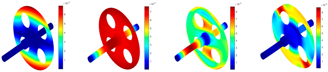 | |||
| 431.03 | 605.50 | 2455.57 | 4604.54 | |
| FEM | 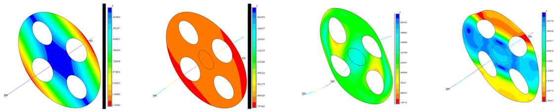 | |||
| 435.42 | 604.59 | 2449.22 | 4509.08 | |
| Difference | −1.01% | −0.14% | 0.26% | 2.12% |
| Present (made of steel) | 418.92 | 526.99 | 2352.40 | 4344.89 |
| Hole Type | Method | Order | |||
|---|---|---|---|---|---|
| 1 | 2 | 3 | 4 | ||
| Round hole | Present | 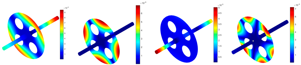 | |||
| 166.34 | 229.09 | 359.62 | 537.02 | ||
| Experiment | 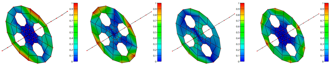 | ||||
| 170.46 | 231.5 | 359.33 | 545.44 | ||
| FEM | 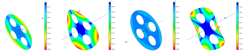 | ||||
| 166.23 | 228.87 | 359.24 | 536.53 | ||
| Difference 1 | −2.42% | −1.04% | 0.08% | −1.54% | |
| Difference 2 | 0.06% | 0.10% | 0.11% | 0.09% | |
| Sector hole | Present |  | |||
| 151.61 | 218.34 | 357.90 | 501.74 | ||
| Experiment | 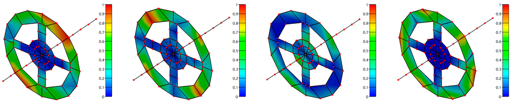 | ||||
| 154.09 | 213.77 | 354.16 | 493.34 | ||
| FEM |  | ||||
| 151.12 | 217.85 | 357.74 | 500.78 | ||
| Difference 1 | −1.61% | 2.14% | 1.06% | 1.70% | |
| Difference 2 | 0.32% | 0.23% | 0.05% | 0.19% | |
Disclaimer/Publisher’s Note: The statements, opinions and data contained in all publications are solely those of the individual author(s) and contributor(s) and not of MDPI and/or the editor(s). MDPI and/or the editor(s) disclaim responsibility for any injury to people or property resulting from any ideas, methods, instructions or products referred to in the content. |
© 2024 by the authors. Licensee MDPI, Basel, Switzerland. This article is an open access article distributed under the terms and conditions of the Creative Commons Attribution (CC BY) license (https://creativecommons.org/licenses/by/4.0/).
Share and Cite
Zhang, H.; Shen, M.; Liu, T.; Li, Z.; Wang, Q. Dynamic Modeling and Vibration Characteristic Analysis of Fiber Woven Composite Shaft–Disk Rotor with Weight-Reducing Holes. Appl. Sci. 2024, 14, 9148. https://doi.org/10.3390/app14199148
Zhang H, Shen M, Liu T, Li Z, Wang Q. Dynamic Modeling and Vibration Characteristic Analysis of Fiber Woven Composite Shaft–Disk Rotor with Weight-Reducing Holes. Applied Sciences. 2024; 14(19):9148. https://doi.org/10.3390/app14199148
Chicago/Turabian StyleZhang, Haibiao, Mengyu Shen, Tao Liu, Zhen Li, and Qingshan Wang. 2024. "Dynamic Modeling and Vibration Characteristic Analysis of Fiber Woven Composite Shaft–Disk Rotor with Weight-Reducing Holes" Applied Sciences 14, no. 19: 9148. https://doi.org/10.3390/app14199148
APA StyleZhang, H., Shen, M., Liu, T., Li, Z., & Wang, Q. (2024). Dynamic Modeling and Vibration Characteristic Analysis of Fiber Woven Composite Shaft–Disk Rotor with Weight-Reducing Holes. Applied Sciences, 14(19), 9148. https://doi.org/10.3390/app14199148