Article

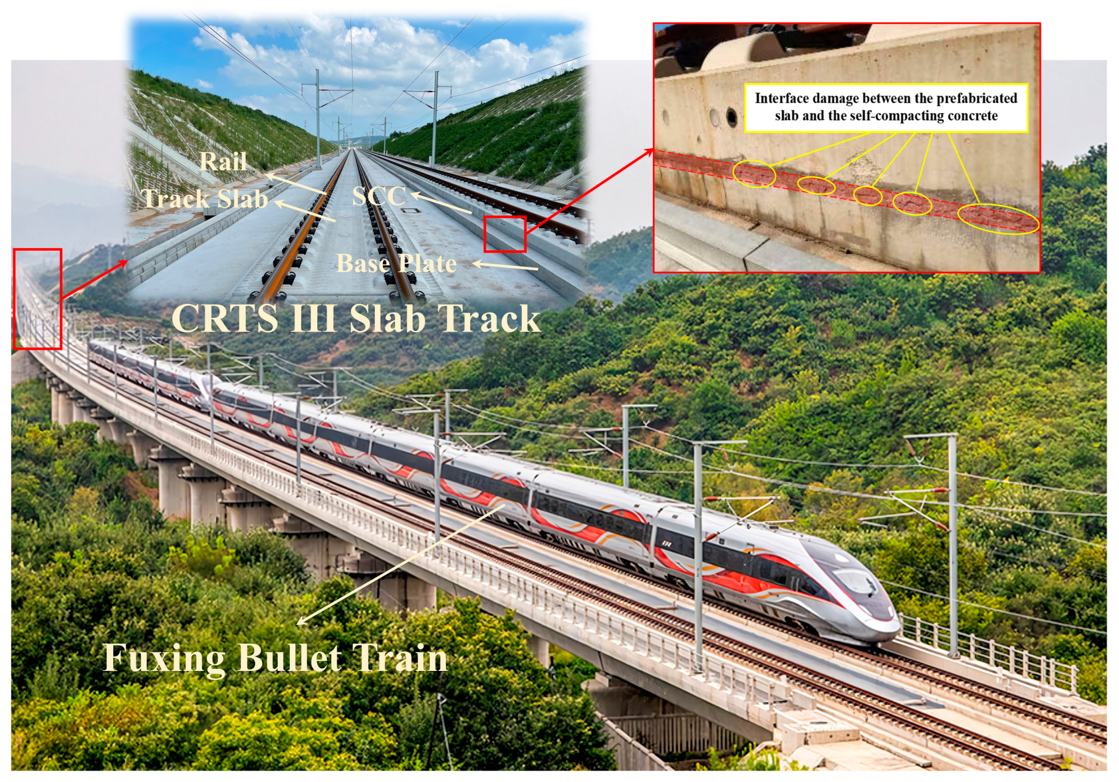
Evolution Mechanism of Interlayer Properties of CRTS III Slab Track during Construction

1
School of Civil Engineering, Beijing Jiaotong University, Beijing 100044, China
2
Zhejiang Institute of Intelligent Transportation, Zhejiang CICO, Hangzhou 310020, China
3
China Railway Engineering Design and Consulting Group Co., Ltd., Beijing 100055, China
4
Anhui Xingyu Track Equipment Co., Ltd., Bengbu 233000, China
*
Authors to whom correspondence should be addressed.
Appl. Sci. 2024, 14(2), 704; https://doi.org/10.3390/app14020704
Submission received: 16 November 2023 / Revised: 9 January 2024 / Accepted: 12 January 2024 / Published: 14 January 2024
(This article belongs to the Special Issue Structural Mechanics in Materials and Construction)

Abstract

:
The interlayer properties of the CRTS III slab track during construction directly affect its long-term service condition. This article introduces time-varying coefficients that characterize the early properties of the interface between track slab and SCC to improve the bilinear CZM. Based on this, an interlayer property evolution model of the CRTS III slab track during construction is established. The evolution mechanism of interlayer properties under complex loads and the influence mechanism of key parameters on them are revealed. The results show that after SCC pouring, the interlayer damage at the corner of the slab becomes a sensitive area due to the combined effects of SCC shrinkage and temperature gradients. Interlayer damage initially manifests at the corner of the slab before progressively spreading toward the center of the slab, influencing the composite performance and force transmission characteristics of the track structure. The interlayer bonding property, shrinkage performance of SCC, and construction temperature substantially affect interlayer damage evolution. To reduce the risk of damage, mineral admixtures and expansion agents can be added as additives to improve the bonding property and minimize shrinkage of SCC. Insulation measures should be taken for SCC during low-temperature construction, and SCC pouring construction below 0 °C and above 30 °C should be avoided.

1. Introduction

Over the past decade, China Railway Track System (CRTS) III slab track has been successfully applied on multiple high-speed railways in China and Indonesia, mainly consisting of track slab, cast-in-place self-compacting concrete (SCC) layers, base plate, etc. (Figure 1). Among them, SCC is poured between the track slab and the base plate [1]. Due to the isolation layer set on the base plate, SCC is only bonded to the lower surface of the track slab [2]. After the completion of construction, due to the combined effects of environmental temperature [3], pouring construction quality [4], and SCC shrinkage [5], the interface between track slab and SCC may produce initial separation [6,7], which is very detrimental to the long-term safe operation of high-speed railways. Therefore, it is necessary to research the evolution law and influencing factors of interface properties during the construction stage.
At present, a minority of researchers have conducted studies on the evolution of interlayer properties during the construction stage of the CRTS III slab track. Liu et al. [8] studied the interlayer stress between track slab and SCC during the construction stage under complex load and foundation deformation conditions and proposed the cause of interface cracking. Wei et al. [9] combined experimental and model simulation methods to study the temperature field and stress field development patterns of SCC with the rapid growth of elastic modulus under different environmental temperatures. Jiang et al. [4] characterized the interlayer quality defects of track slab-SCC using splitting tensile strength, providing a theoretical reference for improving the pouring construction quality of SCC. Some scholars have studied the properties of the track slab-SCC interface in the operation stage of the CRTS III slab track. These previous works can also offer valuable insights for the present study. Cai et al. [10] introduced the plastic damage theory of concrete to establish a nonlinear damage model for slab track and analyzed the interface failure characteristics of track structures under varying roadbed frost heave conditions. Du et al. [11] developed a finite element model to study interface contact loss in the SCC of a slab track under transient impact, achieving two-stage identification of interface damage. Zhu et al. [12] obtained the bonding strength between the prefabricated slab and SCC and analyzed the causes of the interface damage. Sun et al. [13] obtained the failure characteristics and strain evolution law of the interface between track slab and SCC through standard concrete tests. Sheng et al. [14] conducted fatigue tests on ballastless tracks on full-size bridges, and the results showed that the end of the track slab is the weak structural zone under fatigue load conditions. Wang et al. [15] proposed an improved fatigue cohesive zone model (CZM) considering time-varying factors, revealing the evolution mechanism of interface fatigue characteristics of slab tracks. Similar to the CRTS III slab track structure, the CRTS II slab track is also a multi-layer composite structure containing cast-in-place filling layers, and there is also a track slab-CA mortar layer interface. Research on the characteristics of this interface can also serve as a reference for this study. Zhong et al. [16] established a nonlinear cracking model for the interlayer of the CRTS II slab track and analyzed the development process of interlayer separation caused by construction factors such as temperature and tensioning operation. Cai et al. [17] analyzed the development process of joint damage at the end of the track slab and the mechanism of arch instability under the influence of interlayer separation. Zhang et al. [18] analyzed the interlayer separation mechanism of the CRTS II slab track under the coupling effect of temperature gradient and train load. Cui et al. [19] introduced the CZM to build the CRTS II slab track model and studied the effect of temperature on the damage and deformation of the interface between the track slab and CA mortar. Su et al. [20] accurately simulated the interfacial debonding process of a longitudinal continuous slab track by combining on-site experiments, finite element analysis, and machine learning methods. Zhou et al. [21] studied the effect of different temperatures and constraint conditions on the interfacial bonding properties of track slab-CA mortar. Shi et al. [22] proposed a method for accurately evaluating the time-varying reliability of interlayer damage in slab tracks. In addition, some scholars have conducted relevant research on the finite element modeling method of concrete fracture mechanics. Rosso et al. [23] studied the corrosion effects on the capacity and conductivity of concrete half-joint bridges using the finite element method. Li et al. [24] proposed a method for calculating the virtual crack propagation length based on experimental data and constructed a fracture analysis model for studying the parameter discreteness of roller compacted concrete materials. From the above research, it can be seen that the CZM, as a constitutive relationship that expresses the evolution of interlayer characteristics, can accurately reflect the evolution process of interlayer damage in slab tracks. Furthermore, for the CRTS III slab track, the hydration heat after pouring SCC will directly lead to the rapid evolution of the temperature field of the track structure. Therefore, it is crucial to accurately obtain the temperature field of the slab track structure. Zeng et al. [3] built a thermodynamic model for the CRTS III slab track, analyzing the temperature field of the track structure under solar radiation and environmental temperature conditions. Liu et al. [25] conducted full-scale temperature field tests on the CRTS III slab track and obtained its temperature variation characteristics in the natural environment. Zhong et al. [16], Zhang et al. [26], and Zhang et al. [27] analyzed the temperature field and thermal effects of a longitudinally connected slab track under typical climate conditions in Beijing through on-site testing and thermodynamic model simulation methods, respectively. In summary, there are relatively few studies that focus on the interface damage of CRTS III slab tracks during construction. Meanwhile, it should be noted that the constitutive parameters of the new-old concrete interface are theoretically time-varying with the increase in SCC age. In addition, the Young’s modulus, shrinkage load, and heat of cement hydration of the SCC are constantly changing during the construction phase. However, the existing constitutive models and finite element models of the CRTS III slab track pay less attention to this point.
In this paper, taking into account the time-varying parameters of the interface constitutive model between track slab and SCC, a novel multi-field coupled FEM of the CRTS III slab track under construction was established, based on which the interface damage evolution law and its influencing factors were investigated. Specifically, based on the evolution data of strength, stiffness, and fracture energy of new-old concrete with age, an interface time-varying coefficient was proposed, and a bilinear CZM was improved. A multi-field coupled finite element model for the evolution of interlayer damage to the CRTS III slab track during construction was established and validated. The evolution mechanism of interlayer damage to slab tracks during construction was revealed, and the mechanical response of track structures after interlayer damage was analyzed. The influence of key parameters such as interfacial bonding strength, shrinkage of SCC, and environmental temperature on the interlayer characteristics of slab tracks during early construction was discussed. This provides a theoretical reference for effectively controlling the interlayer gap of the slab track during construction.

2. Methods

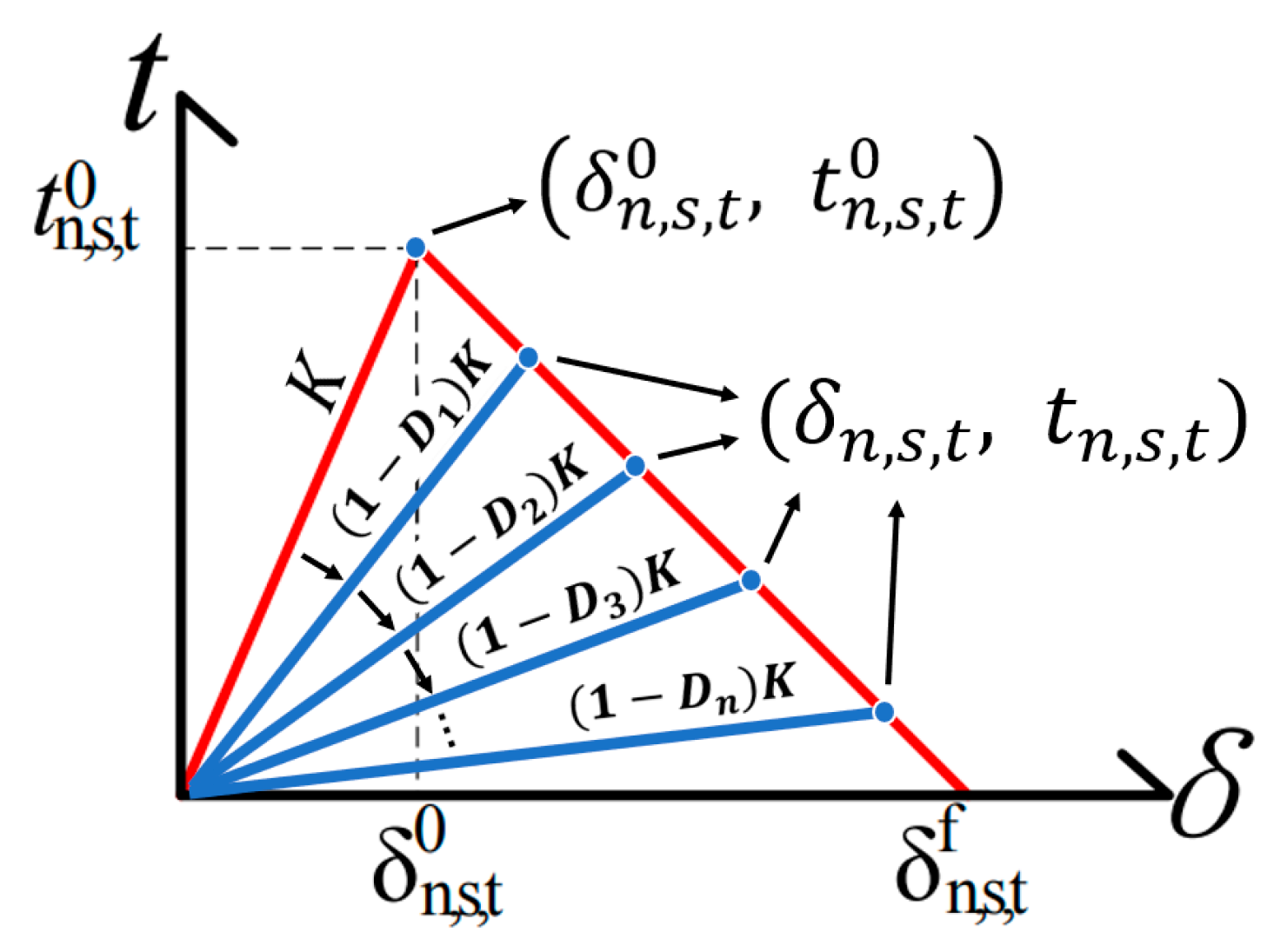
2.1. Interface Constitutive

The interface damage between the track slab and SCC manifests as brittle cracking at the interface between old and new concrete. To simulate such interfacial cracking, a bilinear CZM was employed. The constitutive model is shown in Figure 2.
To describe the constitutive characteristics before the occurrence of damage, the crack initiation factor “DI” was defined according to the quadratic nominal stress criterion [15], which can be expressed as follows:
D I = < t n > t n 0 2 + t s t s 0 2 + t t t t 0 2
where symbol < > indicates that the calculation is performed only when the normal tension is non-negative, and t n , t s , t t represent the stress in the normal direction and the two tangential directions, respectively. It is evident from Figure 2 and the provided formulas that δ n , s , t 0 ,   t n , s , t 0 acts as the demarcation point, delineating the conditions before and after the occurrence of interface damage. This signifies that interface damage initiation commences when the interfacial tension reaches the critical value t n , s , t 0 . Furthermore, the DI value progressively rises from 0 before the interfacial tension attains the interfacial strength t n , s , t 0 . Subsequently, DI increases to 1 precisely when the interfacial tension equals t n , s , t 0 , indicating the initiation of interface damage.
The constitutive parameters of the bilinear CZM encompass interface stiffness K, interface strength t n , t , s 0 , and interface fracture energy G n , t , s 0 . Following the casting of self-consolidating concrete, a contact interface emerges between the new and aged concrete. The CZM parameters K, t n , t , s 0 , and G n , t , s 0 for this interface exhibit an increment with the concrete’s age [28,29], as shown in Figure 3.
From Figure 3, the CZM parameters K, t n , t , s 0 , and G n , t , s 0 all exhibit logarithmic curve characteristics, and the three patterns are relatively similar. In order to facilitate the calculation of the changes in interfacial strength, interfacial stiffness, and interfacial fracture energy with age, a time-varying coefficient 𝜉 by fitting the logarithmic function curve is proposed, ranging from 0 to 1. By multiplying ξ with the original fixed value of the parameters (Table 1), the time-varying interface constitutive parameters that change with the age of SCC can be obtained. This extension enables the generalization of the bilinear CZM to the early-age period of slab track.

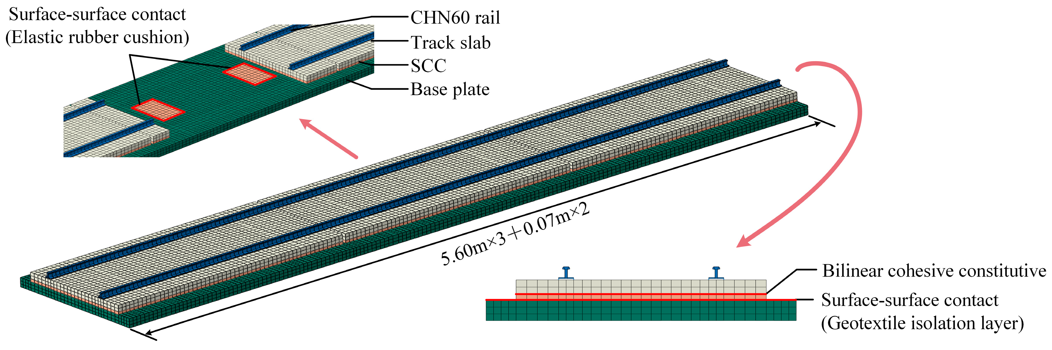
2.2. FEM of CRTS III Slab Track

To make the model more versatile, the finite element model (FEM) of the CRTS III slab track was established using ABAQUS v2021, and the previously developed bilinear CZM with time-varying parameters was implemented using the UFIELD subroutine, as shown in Figure 4.
In Figure 4, in order to eliminate the boundary effect, three track slabs were built, and the middle slab was taken as the research object. The FEM parameters of the main structures are shown in Table 2.
As an important structure of the CRTS III slab track, geotextiles are mainly laid between self-compacting concrete and base plates to reduce the vertical connection between the composite structure of the track slab and self-compacting concrete and the base plate in order to reduce the mechanical response of temperature gradients on the corners and other positions of the track slab. In addition, setting up geotextiles is also beneficial for improving the efficiency of maintenance and replacement of CRTS III slab tracks. To simulate the mechanical behavior of the geotextile between the SCC and the base plate, frictional contact was applied to simulate sliding and friction [32]. Considering the elastic buffering effect of the elastic rubber cushion on the convex platform, the contact between SCC and the convex platform was simulated by friction contact in the tangential direction and linear elastic contact in the normal direction [33,34]. Moreover, since this research focused on the interface damage between the track slab and SCC, the tie constraint was adopted to simplify the connection of the base plate and subgrade, which assumed that there was no debonding or slip between the concrete base and subgrade.

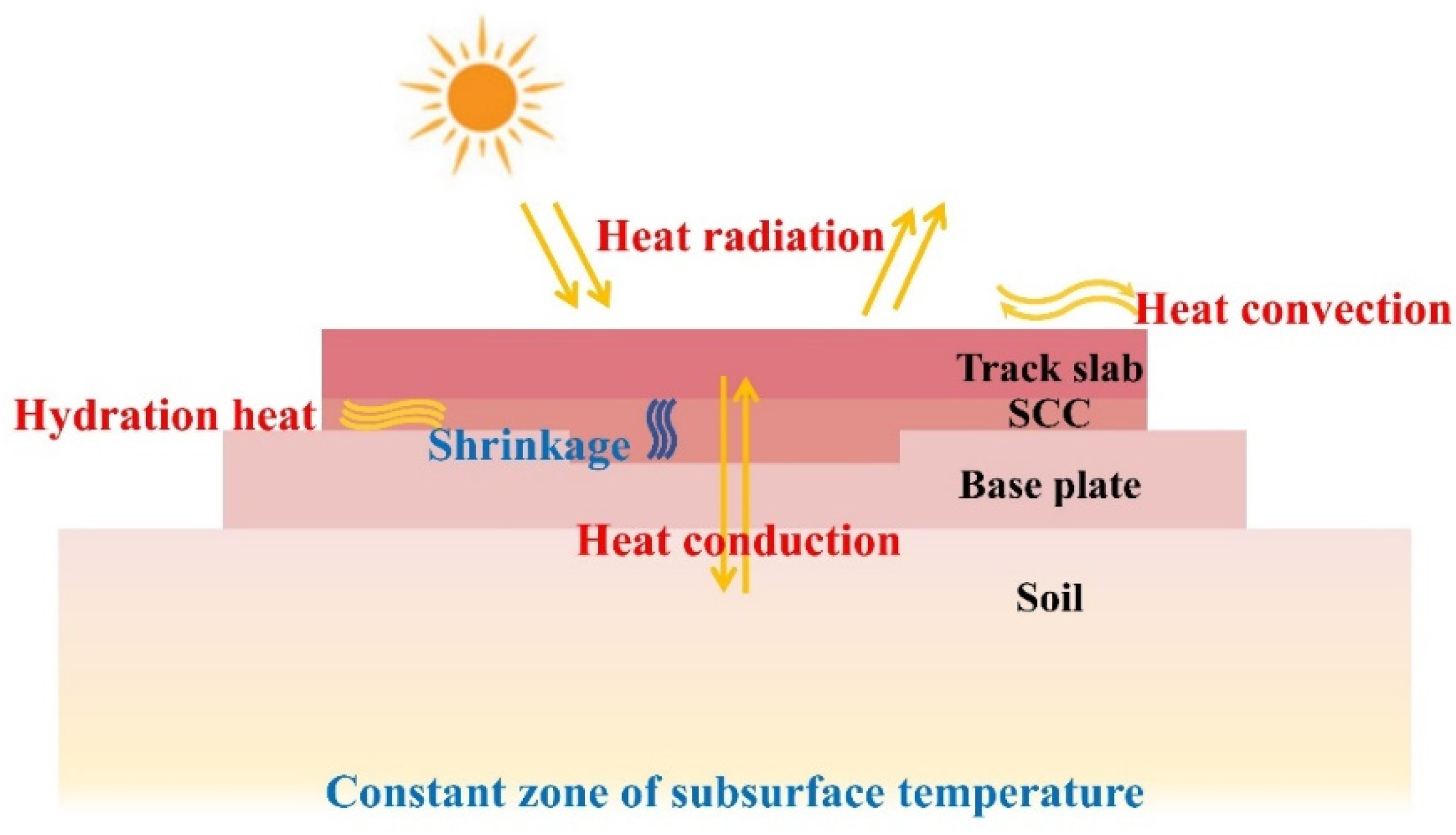
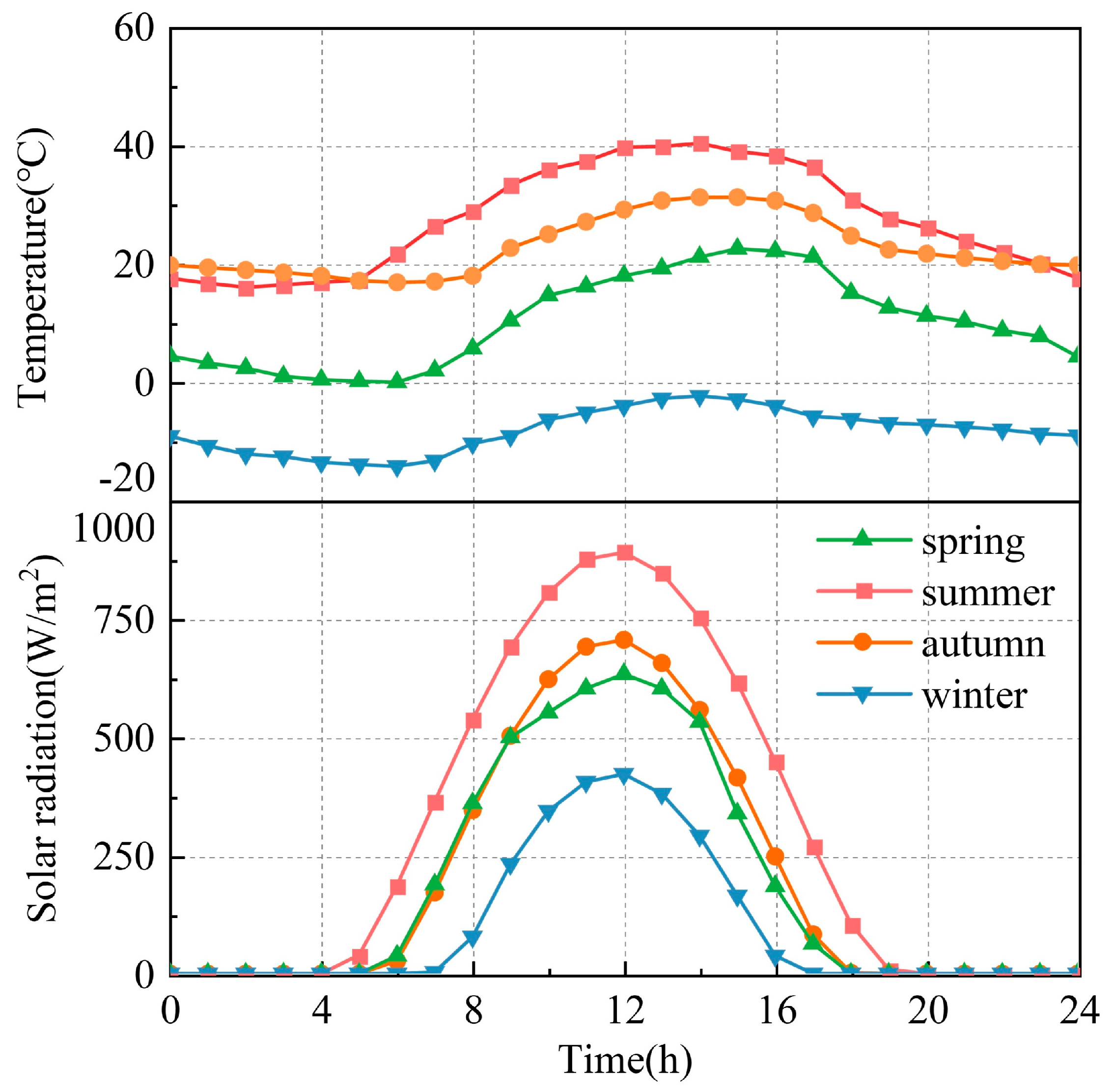
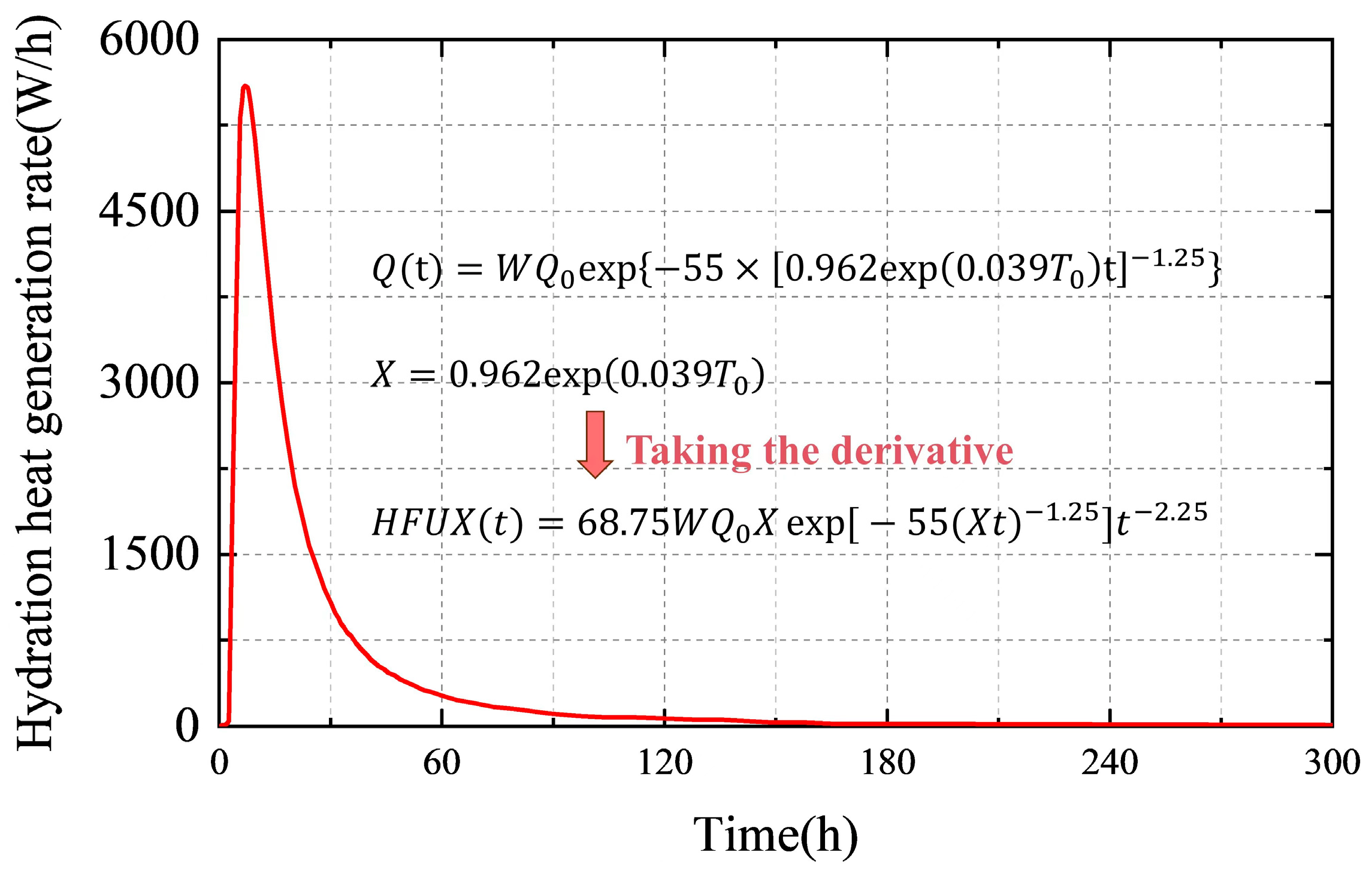
2.3. Coupling of Multiple Loads

Initiating the construction of SCC results in the prompt release of a substantial amount of heat, attributed to the exothermic reactions of concrete hydration. This phenomenon leads to a swift escalation in temperature, thereby amplifying the temperature differential between the track surface and the environmental air. Consequently, the heat exchange between the track surface and the surroundings intensifies. The track surface is subjected to continuous solar radiation, facilitating the substantial conduction of heat along the surface of the track plate into the interior of the track structure. Simultaneously, during the construction phase, a significant portion of heat is transferred from the track to the foundation. Furthermore, on-site investigations have revealed the presence of various issues, including non-standard construction practices, which have been observed to result in the occurrence of shrinkage within the self-consolidating concrete. This observed shrinkage phenomenon is considered a contributing factor to the initiation and progression of interlayer damage within slab track systems. Therefore, the thermal input model during the construction of the slab track is shown in Figure 5.
Heat conduction is primarily determined by the inherent characteristics of the track. Heat convection is primarily determined by solar radiation, the solar radiation absorption coefficient of the track slab, and the solar emissivity of the track slab. According to Ref. [35], the solar radiation absorption coefficient of the track slab was set at 0.65, and the solar emissivity of the track plate was set at 0.88. Heat convection is primarily determined by temperature and wind speed, with the wind speed set to the average value in the Beijing region, specifically 0.6 m/s. Due to the short construction period, there is no seasonal large temperature rise and drop during the construction period, so the daily temperature variation during the construction period is similar. To simplify calculations and mitigate the influence of extreme weather conditions, this study adopted the representative daily temperature and daily solar radiation for each season in the Beijing region, as shown in Figure 6.
According to the hourly cumulative heat of hydration formula proposed in Ref. [36], the rate of hydration heat generation was computed. As an illustrative example, a molding temperature of 20 °C was considered. The results are shown in Figure 7.
From Figure 7, the “Q(t) is called the heat generated by hydration of SCC, the “HFUX(t)” is called the hydration heat generation rate of SCC, the “W” is called the cement content per unit volume of SCC, the “ Q 0 ” is called the final heat of hydration per unit mass of cement, and the “ T 0 ” is called the molding temperature of self-compacting concrete. “t” is the molding time of self-compacting concrete. The hydration heat generation rate of SCC undergoes a substantial initial surge within the first 30 h, followed by a rapid and pronounced decrease. This phenomenon has the potential to induce significant temperature fluctuations within slab track systems over a short timeframe. The hydration heat generation rate curve can serve as a valuable resource for establishing parameters related to hydration heat generation rates in modeling.
Due to the poor quality of SCC pouring and other reasons, SCC may experience shrinkage during the early stages of construction. Therefore, different sets of shrinkage deformation curves for SCC were constructed based on test data [37,38]. Considering that the measured shrinkage curves typically represent real-time monitoring of shrinkage strain during the shrinkage tests without capturing the real-time stress state of concrete under varying elastic modulus, it is important to acknowledge that the stress field induced by concrete shrinkage is an accumulative response process, while the stress field induced by factors such as temperature load is a real-time response process. Neglecting the response characteristics of the shrinkage stress field and directly using the original shrinkage deformation curve in the model for shrinkage stress calculations can often lead to overestimated results. To attain stress results that align more closely with the on-site situation, it becomes necessary to adjust the shrinkage loads. In this study, grounded in Hooke’s law assumptions, an incremental approach was utilized to compute shrinkage and temperature-induced stresses considering time-varying elastic modulus. This study compared stress levels derived through two approaches: one considering cumulative effects (Method A) and the other neglecting cumulative effects (Method B). Stress levels obtained without accounting for cumulative effects were standardized to a reference value of 1 for comparison. The comparative results are shown in Figure 8.
From Figure 8, it is evident that the shrinkage stress levels obtained using Method A are significantly lower than those obtained using Method B. The maximum calculated stress value differs by 54% compared to the results obtained with Method B. This indicates that the cumulative effects of shrinkage loads and time-varying elastic modulus parameters should not be disregarded.
The SCC shrinkage load is considered an equivalent temperature load. The equivalent temperature is applied to the track using the equivalent cooling method. The calculation method for the equivalent temperature is as follows:
T shrinkage t = ε t α
In the above equation, α represents the linear coefficient of expansion for SCC.
From the analysis above, it is evident that the predominant loads sustained by the track during construction can be adequately characterized in the form of temperature loads. In this study, a multi-temperature field load coupling tool was developed, utilizing the UTEMP subroutine, to facilitate the simultaneous application of these loads.

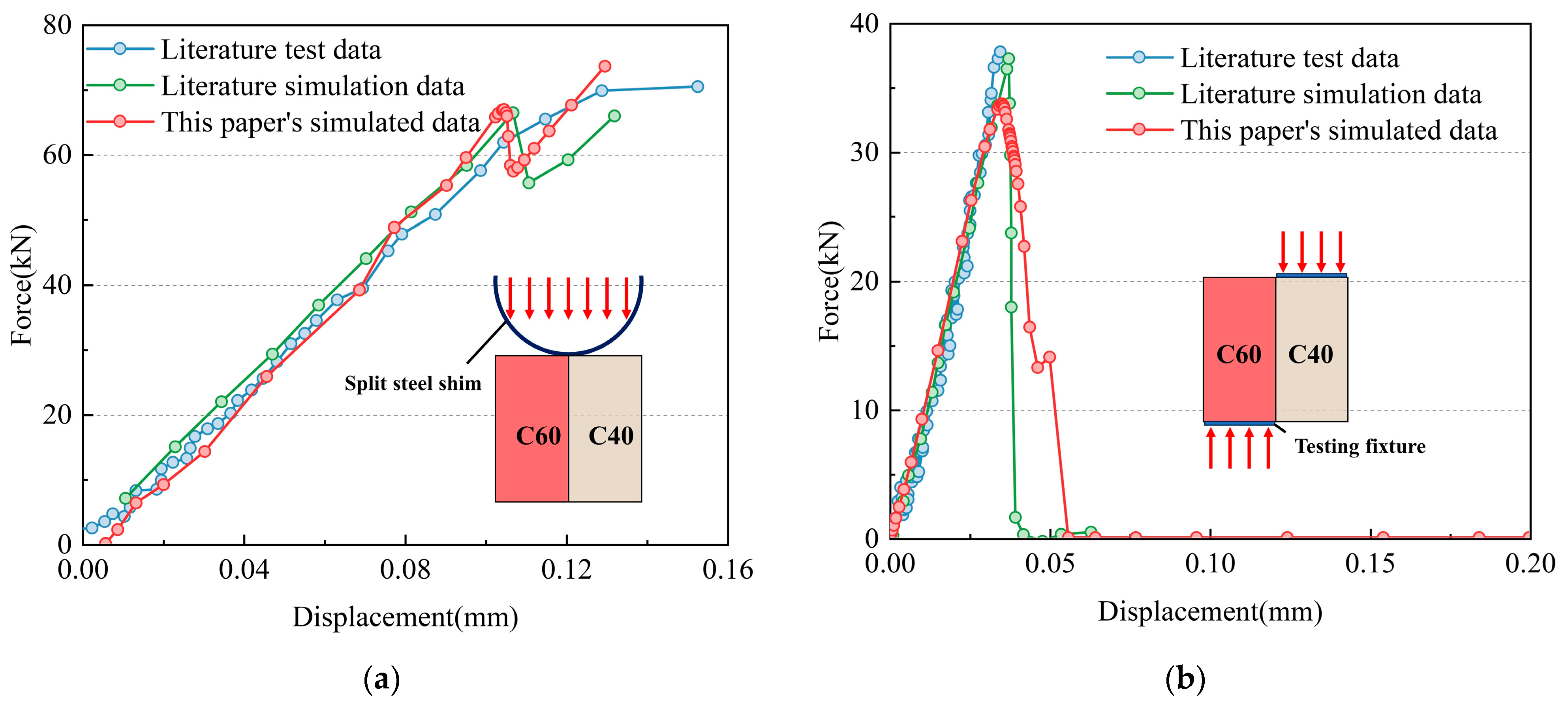
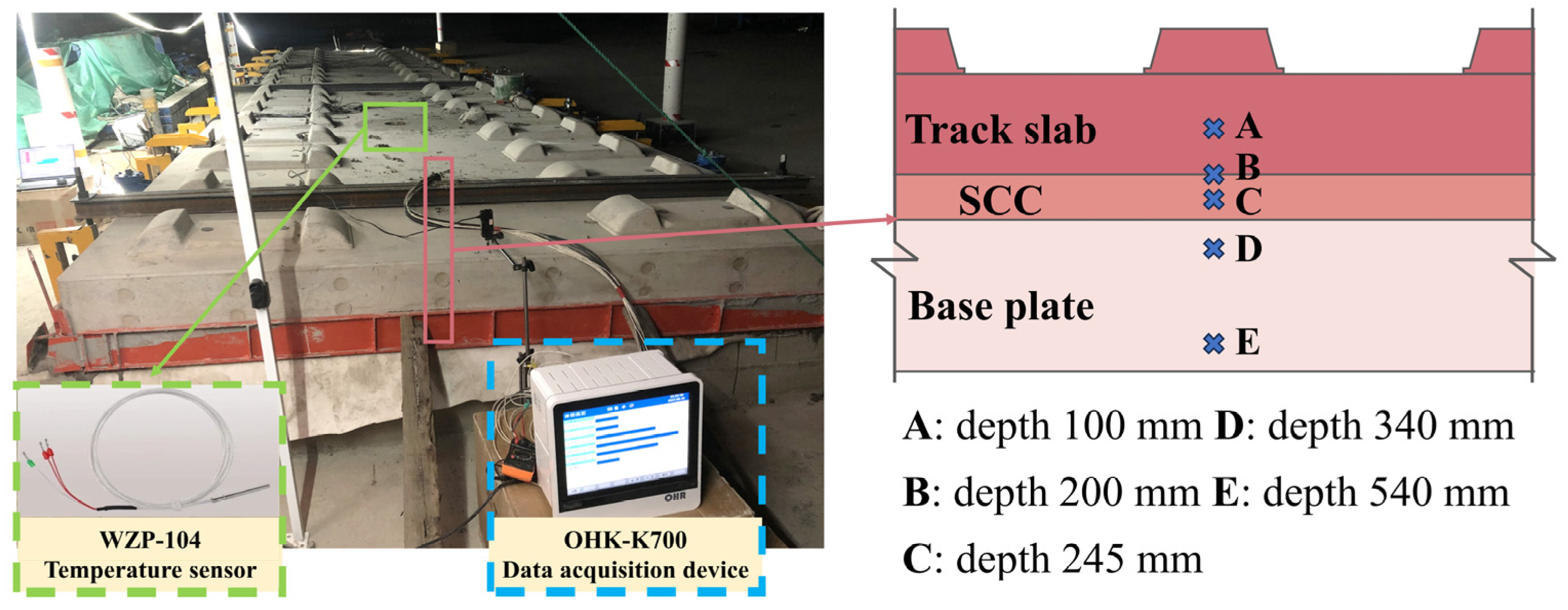
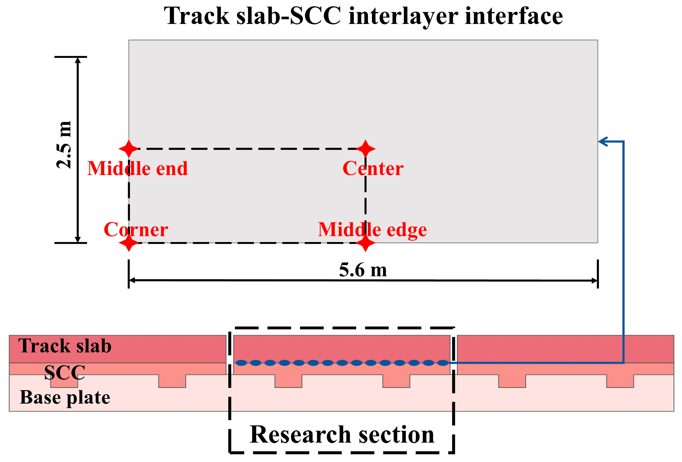
2.4. Model Verification

To validate the accuracy of the interfacial damage constitutive model, the normal tensile test and shear test specimen model based on the interfacial constitutive model proposed in this study were established, which were identical to the test in Ref. [39]. The force-displacement curves were obtained and compared to the test results, as shown in Figure 9.
From Figure 9, it is evident that the numerical model results in this study exhibit good consistency with the test and simulation data presented in the referenced literature. This confirms the validity and correctness of the interfacial damage constitutive model proposed in this study.
To further validate the precision of the thermal input model, real-time temperature monitoring was carried out on the CRTS III slab track, with measuring points positioned at the track’s center. Firstly, measuring points of the temperature sensor were pre-embedded at the grouting hole position of the CRTS III track slab; these measuring points were located at distances of 100 mm, 200 mm, 245 mm, 340 mm, and 540 mm, respectively, from the top surface of the track slab. After the self-compacting concrete layer of the slab track is grouted, the early temperature data of each measuring point can be obtained. In the experiment, a WZP-104 lead-type thermistor temperature sensor and an OHK-K700 type data acquisition instrument were used. The measurement time interval is 1 h, and the measurement accuracy is ±0.15 °C. The configuration of the experimental setup and the placement of the measuring points can be seen in Figure 10. Simultaneously, considering typical summer temperature conditions, the temperature distribution of the slab track was computed, and the track temperatures at various depths were extracted, taking the track’s center position as an example. The simulation results were then compared with the measured results, as shown in Figure 11.
From Figure 11, it was evident that the slab track demonstrates a notable temperature gradient within 0.2 m depth from the surface of the slab. Beyond a depth of 0.2 m, the temperature distribution gradually became more uniform. This can also be confirmed by the coefficient of variation of different measuring points. As the distance from the top surface of the track slab to the measuring points increases, the coefficient of variation of temperature gradually decreases, indicating that the degree of temperature dispersion gradually decreases. The maximum positive temperature gradient in the slab track occurs at 15 o’clock. The simulation results aligned well with the temperature test data obtained from the on-site CRTS III slab track, thereby affirming the precision of the thermal input model.

3. Results and Discussion

After the construction of SCC, under the influence of hydration heat and cyclic environmental temperature, the interface between the track slab and SCC is subjected to the stress caused by the temperature gradient. The high shrinkage characteristics of SCC also affect the stress field at the interface during construction. In the case where the interlayer bonding strength has not yet fully developed, there may be a risk of interlayer damage in the slab track. In addition, the processes, methods, and timing during the construction can also affect the interlayer bonding performance of the slab track. Therefore, it is necessary to explore the evolution characteristics of interlayer damage to the slab tracks and the effect of key construction factors on them.

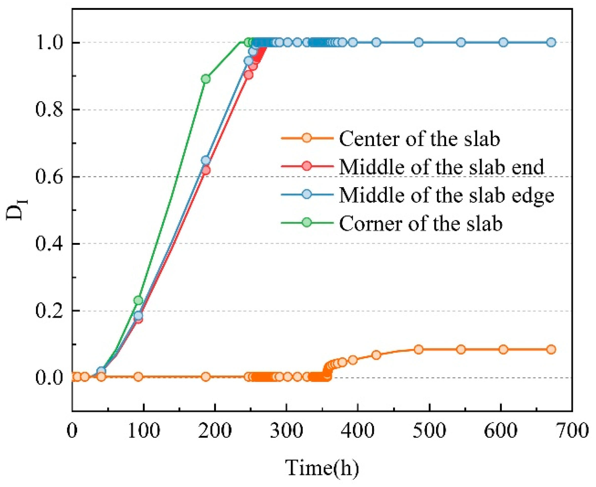
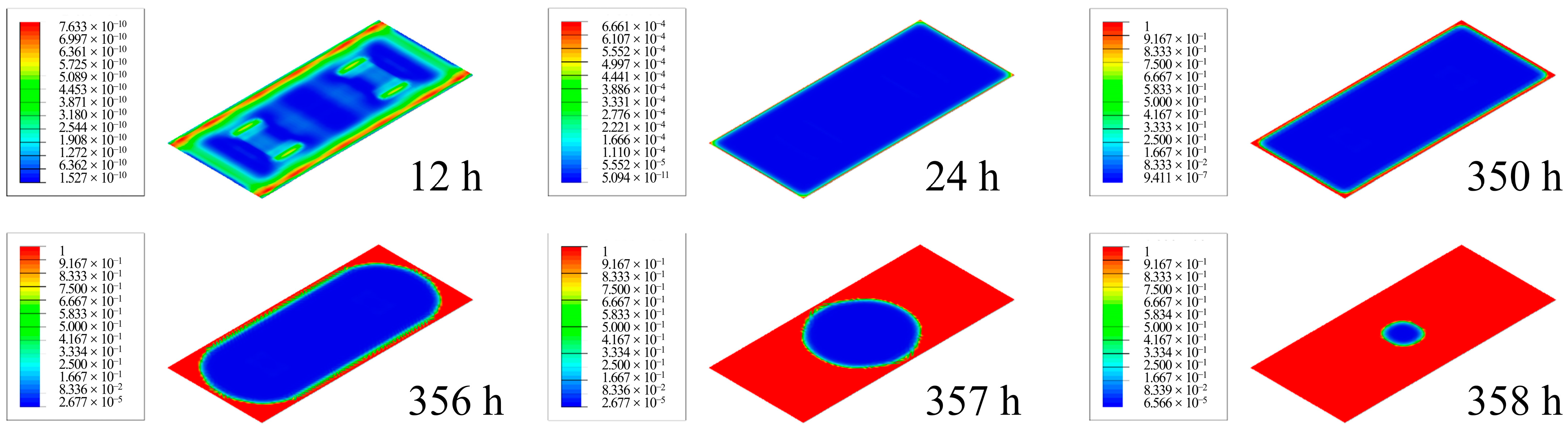
3.1. Evolution Process of Interlayer Damage

Based on the FEM of the slab track under construction and the high-risk position that will cause damage to the track slab-SCC of the CRTS III slab track under various adverse loads caused by temperature, concrete hydration heat, and concrete shrinkage during the construction period, the general regularity of damage development was explored, and the negative effects of damage on the mechanical characteristics of the track slab were also clarified. In this article, the crack damage at the interface between the track slab and SCC was studied. Therefore, the key points were selected as the corner of the slab, the middle of the slab end, the middle of the slab edge, and the center of the slab, as shown in Figure 12. Furthermore, DI time history curves at the four positions after pouring SCC are extracted, as shown in Figure 13.
As is shown in Figure 13, at the corner of the slab, the DI appears the earliest and develops the fastest, which indicates that the corner of the slab is the most sensitive position at the initial stage of SCC construction. The development of the DI at the end of the slab and the middle of the slab edge is slower. This is due to the different shrinkage amounts of SCC at different positions. At the middle of the slab end and the middle of the slab edge, SCC only experiences transverse or longitudinal unidirectional shrinkage, while at the corner of the slab, SCC experiences shrinkage in both longitudinal and transverse directions. Furthermore, the corners of the slab are subjected to significant stress due to temperature gradients, which increases the risk of damage to the area. However, the development of the DI at the center of the slab is very slow, which has not reached 1. It means that the cracking condition has not been achieved. To represent the overall characteristics of interlayer cracking intuitively, the distribution diagram of DI at different times on the interface is shown in Figure 14.
As is shown in Figure 14, the final setting of SCC ends at 12 h, and the interlayer has some self-healing ability. There is nearly no damage at the interface, and DI is basically in the order of 10−10. At 24 h, as the SCC shrinks, the cloud pattern distribution changes significantly, and the peak value of DI mainly appears in the narrow area around the interface. As the shrinkage continues to develop, the peak value of DI gradually increases to 1 around the interface, indicating that the interface has entered the crack stage. Subsequently, the peak distribution area of DI continuously expands towards the interior of the interface over time, but the rate is relatively low. At 350 h, the area where no damage occurred between layers was overall in a “chamfered rectangle” shape. This indicates that although SCC has a relatively fast shrinkage rate in the early stage after pouring, its lower elastic modulus has not been able to cause rapid cracking between layers. Furthermore, the cracking region of the interface begins to develop rapidly, especially at the corner of the slab, where the development rate of the cracking region is significantly faster than the middle of the slab edge. At 356 h, the area of the crack area showed significant and rapid growth, with the growth pattern approaching the center of the track board from the corners, and the fastest growth was in the diagonal direction. The development rate of the longitudinal direction is higher than that of the transverse direction, which is consistent with the phenomenon observed in the field. At this point, the uncracked area between layers gradually decreases from a “chamfered rectangle” to a “capsule-shaped” area, and the end of the slab has fully penetrated. At 357 h, the cracking region rapidly develops further into the slab and penetrates at the edge of the slab, ultimately causing extensive damage to the entire interface.
In summary, the shrinkage of SCC is the main cause of the initial crack at the corner of the slab of the CRTS III slab track. The corner of the slab is the most sensitive location for cracking, followed by the edges of the slab, and the center of the slab is the least sensitive. It is worth noting that to illustrate the general pattern of interlayer cracking between track slab and SCC, this paper has constructed a shrinkage curve with a high rate and large quantity. In practice, the shrinkage performance of SCC is not so poor. Based on the clear cracking pattern and its influencing factors, more detailed requirements for interlayer bonding performance will be proposed in the following text.

3.2. Mechanical Characteristics of Slab Track after Interlayer Damage

The interlayer damage will directly affect the overall stress state of the track structure. To clarify the impact of interlayer damage on the overall stress characteristics of the slab track, the vertical displacement of key positions of SCC with and without considering damage was extracted, as shown in Figure 15.
From Figure 15, it can be seen that the vertical displacement characteristics of SCC have significantly changed before and after considering damage. Before 356 h, the vertical displacement was basically the same, but after 356 h, the displacement at the corner of the slab considering damage increased significantly, suddenly reaching about 4.4 mm in just 2 h. The position at the center of the slab also plummeted to about 4.4 mm, and the displacement at these positions remained the same. If the damage is not considered, the vertical displacement at the center of the slab will continue to increase. This is because before 356 h, there was only damage at the corner of the interlayer, and the overall bonding performance still exists. Therefore, non-coordinated deformation occurred under the action of the shrinkage load. After 356 h, rapid cracking occurred at the interlayers, and there was no interface stiffness between the layers to coordinate the deformation of the upper and lower layers of the composite slab. When the cracking area extended to the slab, the bonding between the track slab and SCC had completely disappeared. The track slab and SCC rebounded due to the disappearance of bonding stress, and the disappearance of the bonding surface ultimately made the vertical deformation coordinated and consistent. Therefore, the shrinkage corresponding to 356 h can also be regarded as the critical shrinkage corresponding to an interlayer interface age coefficient of 1. Furthermore, to explain the general law of layer cracking between track slab and SCC, MISES stress distribution diagrams of the lower surface of the track slab with and without damage were extracted, respectively, as shown in Figure 16, to reveal the influence of cracking on the stress distribution of the interlayer.
As shown in Figure 16, it can be seen that the distribution pattern of MISES stress before cracking is basically consistent at different times, with the peaks of DI concentrated at the edge of the slab and slowly increasing over time. After considering interlayer damage, the stress distribution and magnitude are nearly the same as those without considering damage within 356 h after pouring SCC. However, after 356 h, the stress at the corner of the slab decreased sharply, and the peak of DI appeared range contracted from the edge to the center of the slab. The MISES stress at the center of the slab did not increase continuously but decreased to 25% at 672 h. This is because the accumulated strain energy overcame the fracture energy, and the strain energy was released. In summary, the interlayer cracking destroys the mechanical properties of the composite slab and changes the force transmission characteristics of the structure. and makes the limit of the multi-layer structural system entirely dependent on the friction force between the track slab and SCC.

3.3. Influence of Key Factors on the Evolution of Interlayer Damage

In Section 3.1, it has been determined that the corner of the slab track presents a high-risk area for interlayer cracking and damage. It is crucial to reduce the risk of cracking and damage at this location. Consequently, this section concentrates on two key parameters, namely DI and vertical displacement, to investigate the influence of different factors on the evolution mechanism of interlayer damage. Although the size parameters of the track slab may significantly affect the early properties of the interface, the CRTS III slab track has already been standardized and is not suitable for wide-ranging modifications in the future. Therefore, this paper mainly focuses on the influence of construction factors.

3.3.1. Interlayer Bonding Property

After the cast-in-place of SCC, the bonding performance at the interface between the track slab and SCC gradually develops. To investigate the influence of interlayer bonding performance between the track slab and SCC on the evolution of interlayer damage, four different working conditions were constructed with interlayer bonding performance reduction coefficients of 1/3, 1/2, 2/3, and 1. Among them, a smaller reduction coefficient represents better interlayer bonding performance, and when the reduction coefficient is 1, it indicates that no reduction has been performed. A comparison of DI and vertical displacement time-history curves at different reduction coefficients for the corner of the slab is shown in Figure 17.
From Figure 17a, it can be observed that there is a significant difference in the development rate of DI under different reduction coefficients, and it notably decreases with the growth of the interlayer bonding performance. This is because DI is mainly in the ascending segment of the CZM, and the development rate of this segment is primarily controlled by interfacial strength, and the interfacial strength exhibits a linear increase trend with the growth of the reduction coefficient, which results in a reduction in the development rate of DI. From Figure 17b, it can be seen that the shape of the vertical displacement curve of the corner of the slab remains relatively consistent under different bonding properties. With the increase in the reduction coefficient, the abrupt displacement time of the corner exhibits a nonlinear growth trend. When the reduction coefficient is 1/3, the corner experiences an abrupt displacement at 146.8 h, while for the reduction coefficient of 1, the corner experiences an abrupt displacement at 354.5 h. The magnitude of the abrupt vertical displacement also increases, with a value of 2.11 mm when the interfacial age reduction coefficient is 1/3 and 4.42 mm when it is 1. Overall, the values and times of abrupt displacement at the corner of the slab tend to exhibit nonlinear growth as the reduction coefficient increases. The rate of their development gradually decreases. This is because, with the increase in the reduction coefficient, the interlayer damage development rate at the corner of the slab continuously decreases. The equivalent critical shrinkage corresponding to extensive interlayer debonding also increases continuously, making interlayer debonding less likely to occur.

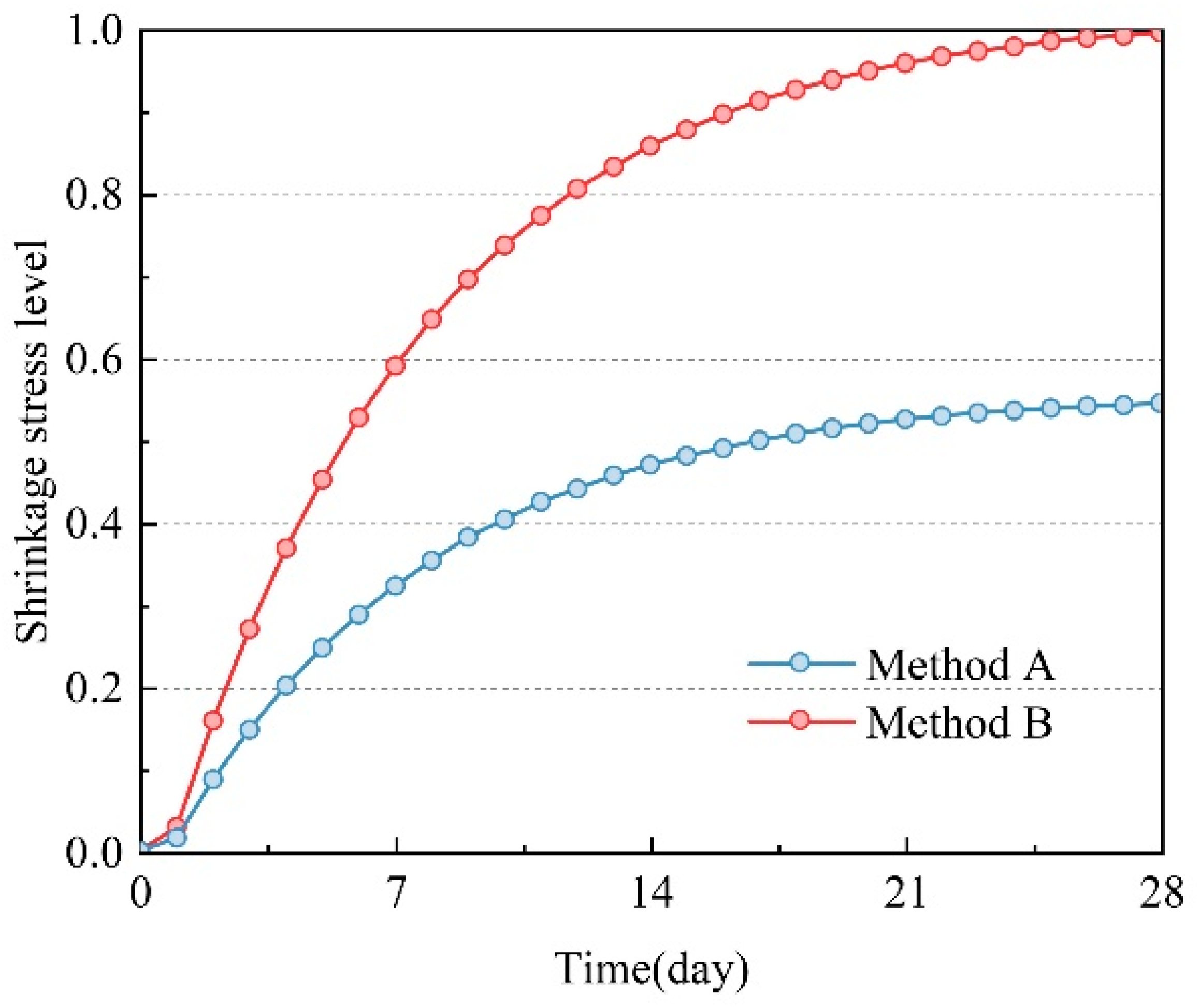
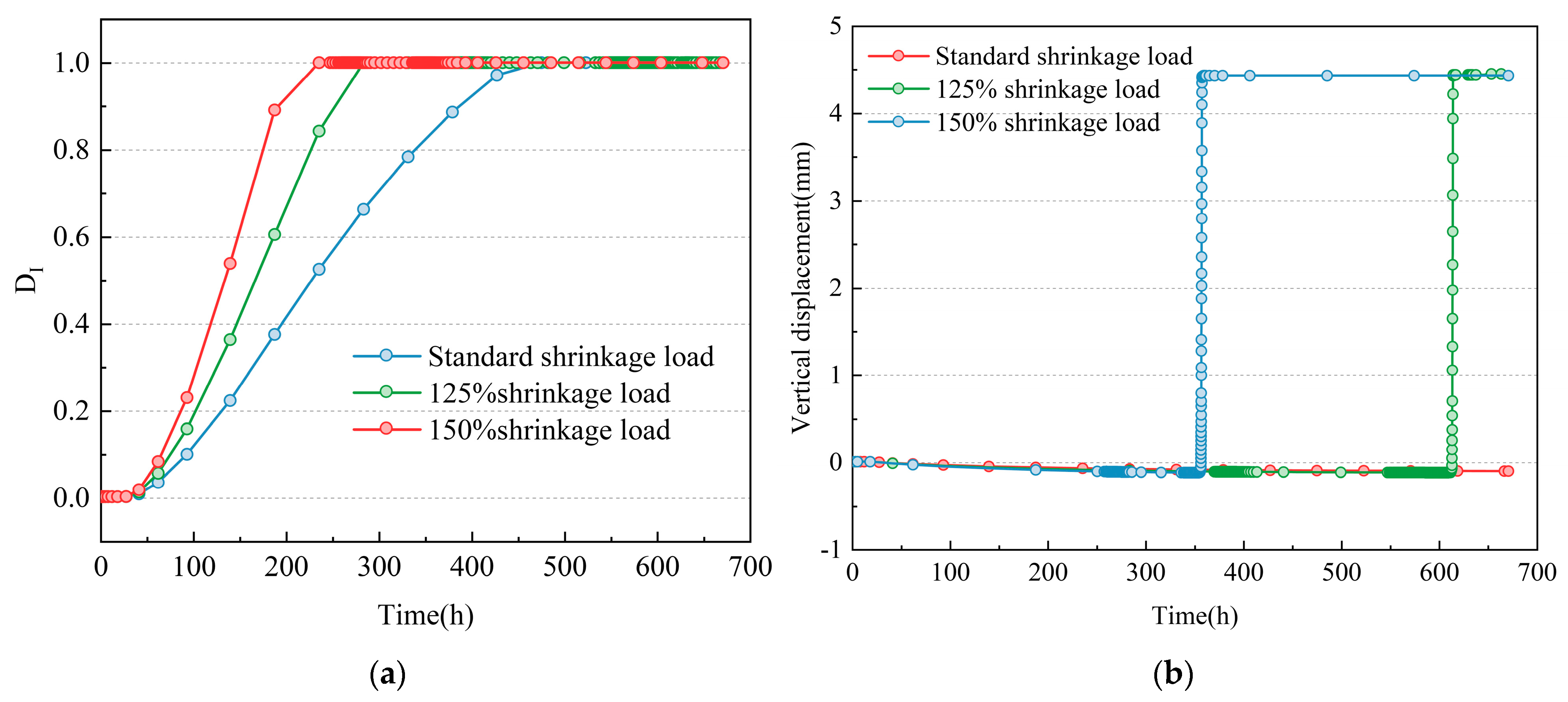
3.3.2. Shrinkage Performance of SCC

The shrinkage performance of SCC is related to the curing conditions. When improperly cured, the increment of shrinkage deformation can exceed 60% [40,41], directly affecting the interfacial cracking and damage. In this section, based on the standard shrinkage deformation with proper curing, shrinkage deformations of 125% and 150% were constructed to represent improper curing while keeping the bonding performance constant (the reduction coefficient is 1). The corner of the slab was the focus of the section, and the cracking factor and vertical displacement under different shrinkage loads were extracted, as shown in Figure 18.
From Figure 18a, it can be observed that with the increase in shrinkage load, the magnitude of DI at the same age increases, and the development rate becomes faster. In terms of magnitude, the relative cracking rate shows nonlinear growth with increasing shrinkage load. To facilitate the analysis of interfacial damage evolution rates under different shrinkage loads, the relative cracking rate is defined as follows:
Δ v c r a c k i n g = t s t a n d a r d c r a c k i n g t n c r a c k i n g
where t n c r a c k i n g represents the corner of the slab cracking time corresponding to the nth contraction load and t s t a n d a r d c r a c k i n g represents the slab cracking time corresponding to the standard shrinkage curve. By calculation, it can be concluded that when the shrinkage load is 1.25 times the original load, the relative cracking rate is 1.66 times that of the standard shrinkage load; when the shrinkage load is 1.5 times the original load, the relative cracking rate is 2.01 times that of the standard shrinkage load. The rate of increase in the relative cracking rate is much greater than the rate of increase in the shrinkage load. Therefore, in the process of formulating SCC, it is essential to strictly control the use of cementitious materials to ensure the volume stability of SCC and prevent excessive shrinkage deformation. From Figure 18b, it can be observed that under the standard shrinkage load, there is no abrupt vertical displacement of the slab corner, indicating that the standard shrinkage load has not reached the critical shrinkage displacement for interlayer debonding. When the shrinkage load increases to 125% of the standard shrinkage load, the corner displacement undergoes an abrupt change. Furthermore, as the shrinkage load further increases to 150%, the time of displacement abruptly changes. This is because the faster shrinkage load enables the SCC to reach the critical shrinkage displacement earlier, thereby advancing the timing of the abrupt change in displacement.

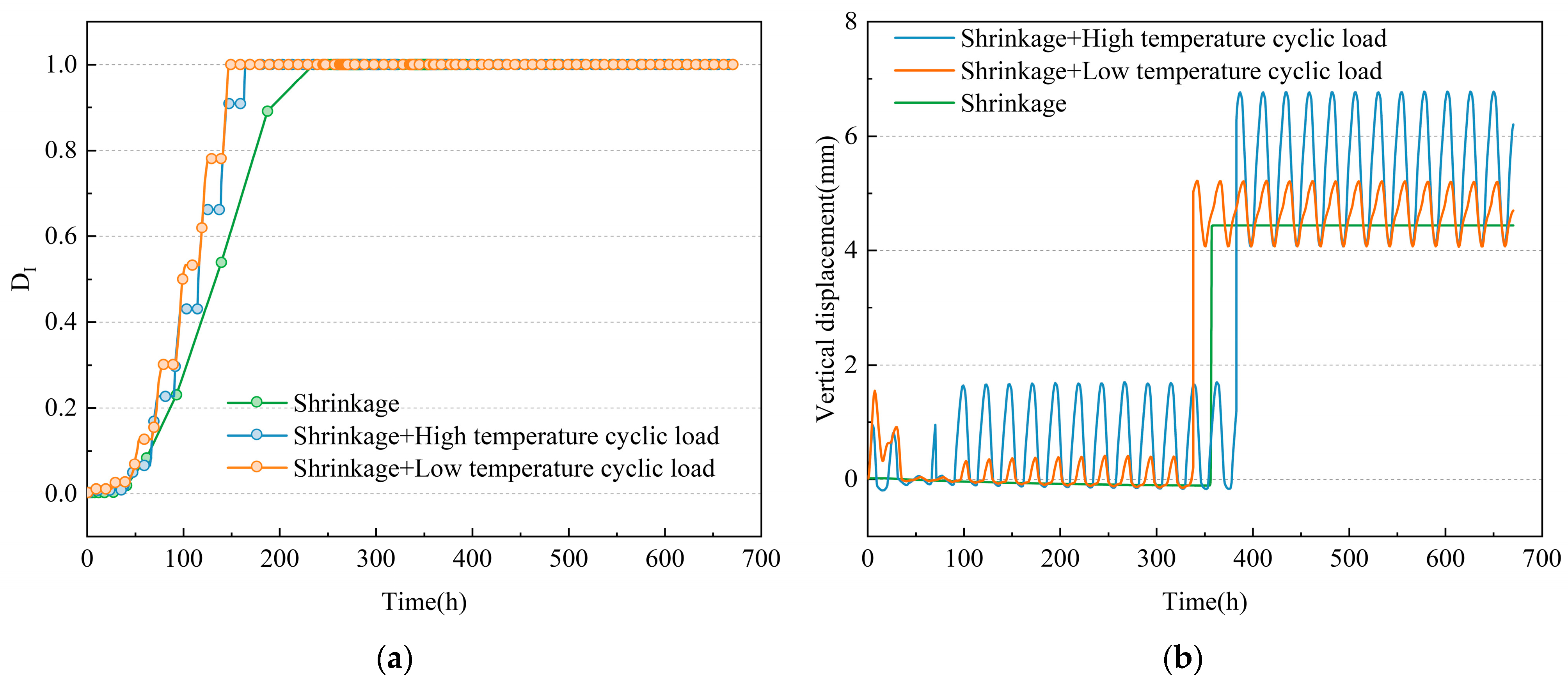
3.3.3. Construction Temperature

Furthermore, to clarify the influence of construction temperature on interfacial cracking characteristics, this section took the temperature characteristics of Beijing, as shown in Figure 6, as an example. It selected the daily temperature cyclic loads during the summer high-temperature period and winter low-temperature period with the largest temperature field difference in a year. It compared the effects of different construction temperatures on interlayer damage. It extracted DI and vertical displacement time history curves of the corner of the slab under standard shrinkage load, as shown in Figure 19.
From Figure 19a, it can be observed that under the combined influence of the winter low-temperature and summer high-temperature cyclic temperature fields, along with the shrinkage field in Beijing, DI exhibits distinct step-like characteristics. The development time and rate of DI for the corner of the slab during low-temperature operations are faster than during high-temperature operations. Moreover, the duration of the step-like plateau period of DI during low-temperature operations is shorter compared to high-temperature operations. This is mainly due to the superimposition of the shrinkage of SCC with low-temperature cyclic loads, making it more susceptible to environmental influences and resulting in a faster rate of damage development. From Figure 19b, it can be observed that interlayer debonding in high-temperature summer conditions occurs later than under the condition of shrinkage alone. In contrast, interlayer debonding in low-temperature winter conditions occurs earlier than under the condition of shrinkage alone. This indicates that casting SCC in the winter is more unfavorable for maintaining interlayer bonding performance. Considering the overall characteristics of Beijing’s summer and winter temperatures, construction during low-temperature conditions below 0 °C has a more adverse impact on maintaining interlayer bonding performance. Construction at low temperatures should strictly implement insulation measures to prevent rapid temperature decreases in the core of SCC, which can lead to interlayer cracking. In addition, to guarantee stable SCC performance, the construction temperature should not exceed 30 °C.

4. Conclusions

This paper focused on the issue of cracking between the slab track and the SCC of the CRTS III slab track during construction. A time-dependent damage model was established for the interlayer of the slab track during construction while considering time-varying parameters and loads between layers. Interlayer damage evolution and the influence of key factors on damage evolution were systematically analyzed. The conclusions are as follows:
A time-varying coefficient was proposed that can simultaneously reflect the interfacial strength, stiffness, and fracture energy evolution between track slab and SCC at an early age. Based on this, the bilinear CZM was modified and introduced into the interlayer damage evolution model of the CRTS III slab track during construction using a UFIELD subroutine. This model can better describe the time-dependent damage between the track slab and SCC during construction.
After SCC pouring construction is finished, the corner of the slab is a sensitive area for interlayer cracking, mainly due to the combined effect of longitudinal and transverse shrinkage of SCC as well as significant interfacial stress caused by temperature gradients.
Under unfavorable conditions of construction load, the interface cracks between the track slab and SCC appear first at the corner of the slab. Gradually, the cracking area extends towards the center of the slab and successively penetrates to the end and the edge of the slab. Interlayer cracking negatively impacts the composite performance and changes the force transmission characteristics of the track structure.
The interlayer bonding property and SCC shrinkage performance significantly affect the evolution process of interlayer damage. Specifically, the better the interlayer bonding property and the smaller the shrinkage performance of SCC, the later the occurrence of interlayer damage. To reduce the risk of cracking, the bonding and anti-shrinkage properties of SCC can be improved by adding viscosity modifiers, expansion agents, etc.
Low construction temperatures are less favorable for the interlayer properties of the slab track. Construction in low temperatures below 0 °C should be avoided as much as possible. During low construction temperatures, it is crucial to take strict insulation measures to prevent the SCC core temperature from dropping too fast and adopt strict and standardized concrete maintenance plans. In addition, to guarantee stable SCC performance, the construction temperature should not exceed 30 °C.

Author Contributions

Conceptualization, L.G.; methodology, J.W., L.W. and W.Z.; software, J.W., W.Z. and Y.Q.; validation, L.G. and W.Z.; investigation, J.W., L.W. and W.Z.; writing—original draft preparation, W.Z., C.H. and Y.L.; writing—review and editing, J.W., L.W. and Y.Q.; visualization, J.W. and L.W.; supervision, L.G.; project administration, L.G. All authors have read and agreed to the published version of the manuscript.

Funding

This research was funded by the Fundamental Research Funds for the Central Universities (Science and technology leading talent team project, 2022JBQY009), the Fundamental Research Funds for the Central Universities (No. 2020JBZD013), the 111 Project (B20040), the Science and Technology Research and Development Project of China State Railway Group Co., Ltd. (P2021G053), and the Research Program of the Shandong Department of Transportation (2021B99).

Institutional Review Board Statement

Not applicable.

Informed Consent Statement

Not applicable.

Data Availability Statement

The data presented in this study are available on request from the corresponding author. The data are not publicly available due to privacy.

Conflicts of Interest

The authors declare no conflicts of interest. The funders had no role in the design of the study; in the collection, analyses, or interpretation of data; in the writing of the manuscript; or in the decision to publish the results.

References

  1. Deng, S.; Zhang, Y.; Ren, J.; Yang, K.; Liu, K.; Liu, M. Evaluation index of CRTS III prefabricated slab track cracking condition based on interval AHP. Int. J. Struct. Stab. Dyn. 2021, 21, 2140013. [Google Scholar] [CrossRef]
  2. Cai, X.; Zhang, Q.; Wang, Q.; Cui, X.; Dong, B. Effects of the subgrade differential arch on damage characteristics of CRTS III slab track and vehicle dynamic response. Constr. Build. Mater. 2022, 327, 126982. [Google Scholar] [CrossRef]
  3. Zeng, R.; Zhang, J.; Hu, W.; Jin, C. Study on the Evolution Characteristics of Temperature Field in CRTS III Ballastless Track Slab. Railw. Stand. Des. 2022, 66, 35. [Google Scholar]
  4. Jiang, W.; Xie, Y.; Li, W.; Long, G. Influence of bubble defects on the bonding performance of the interlayer interface of the CRTS III slab ballastless track structure. Constr. Build. Mater. 2021, 307, 125003. [Google Scholar] [CrossRef]
  5. Liu, R.; Song, L.; Cao, J.; Xia, Z.; Yu, Z. Early warping deformation of high-speed railway CRTS III track slabs. Eng. Struct. 2023, 294, 116651. [Google Scholar] [CrossRef]
  6. Bhogone, M.; Subramaniam, K.V. Improvement in early-age cracking performance of concrete with hybrid steel-macropolypropylene fiber blends. Mater. Today Proc. 2022, 65, 1589–1593. [Google Scholar] [CrossRef]
  7. Li, L.; Dao, V.; Lura, P. Autogenous deformation and coefficient of thermal expansion of early-age concrete: Initial outcomes of a study using a newly-developed Temperature Stress Testing Machine. Cem. Concr. Compos. 2021, 119, 103997. [Google Scholar] [CrossRef]
  8. Shaofei, L. Cause Analysis of Interlayer Seams of CRTS III Slab Ballastless Track. Railw. Eng. 2017, 4, 106–109. [Google Scholar]
  9. Wei, C.; Yang, R.; Zhang, G.; Chang, F.; Sun, Z. Research on the Early Temperature Field of Self-compacting Concrete of Ballastless Track and its lnfluence. Railw. Stand. Des. 2021, 65, 22–27. [Google Scholar] [CrossRef]
  10. Cai, X.; Zhang, Q.; Zhang, Y.; Wang, Q.; Luo, B.; Yang, G.; Lau, A. Deformation law and control limit of CRTSIII slab track under subgrade frost heave. Appl. Sci. 2021, 11, 3520. [Google Scholar] [CrossRef]
  11. Du, W.; Ren, J.; Zhang, K.; Deng, S.; Zhang, S. Two-stage identification of interlayer contact loss for CRTS III prefabricated slab track based on multi-index fusion. J. Zhejiang Univ. Sci. A 2023, 24, 497–515. [Google Scholar] [CrossRef]
  12. Zhu, K.; Wu, B.; Zeng, Z.; Liu, B. Reason Analysis of the Gap between CRTS Slab and Self Compacting Concrete. In Proceedings of the International Conference on Education, Management, Computer and Society, Shenyang, China, 1–3 January 2016; pp. 626–629. [Google Scholar]
  13. Sun, S.; Xu, Q. Experimental study on the interface fatigue between track slab and self-compacting concrete for CRTS III slab track. Eng. Fail. Anal. 2023, 150, 107302. [Google Scholar] [CrossRef]
  14. Sheng, X.-W.; Zheng, W.-Q.; Zhu, Z.-H.; Qin, Y.-P.; Guo, J.-G. Full-scale fatigue test of unit-plate ballastless track laid on long-span cable-stayed bridge. Constr. Build. Mater. 2020, 247, 118601. [Google Scholar] [CrossRef]
  15. Wang, J.; Gao, L.; Zhao, W.; Zhong, Y.; Tong, F.; Wang, Q. Evolution mechanism of interlayer fatigue properties of CRTS III slab track. Constr. Build. Mater. 2022, 360, 129459. [Google Scholar] [CrossRef]
  16. Zhong, Y.; Gao, L.; Zhang, Y. Effect of daily changing temperature on the curling behavior and interface stress of slab track in construction stage. Constr. Build. Mater. 2018, 185, 638–647. [Google Scholar] [CrossRef]
  17. Cai, X.-P.; Luo, B.-C.; Zhong, Y.-L.; Zhang, Y.-R.; Hou, B.-W. Arching mechanism of the slab joints in CRTSII slab track under high temperature conditions. Eng. Fail. Anal. 2019, 98, 95–108. [Google Scholar] [CrossRef]
  18. Zhang, Y.; Wu, K.; Gao, L.; Yan, S.; Cai, X. Study on the interlayer debonding and its effects on the mechanical properties of CRTS II slab track based on viscoelastic theory. Constr. Build. Mater. 2019, 224, 387–407. [Google Scholar] [CrossRef]
  19. Cui, X.; Du, B.; Xiao, H.; Zhou, R.; Guo, G.; Liu, H. Interface damage and arching mechanism of CRTS II slab track under temperature load. Constr. Build. Mater. 2021, 291, 123258. [Google Scholar] [CrossRef]
  20. Su, M.; Xie, H.; Kang, C.; Li, S. Determination of the interfacial properties of longitudinal continuous slab track via a field test and ANN-based approaches. Eng. Struct. 2021, 246, 113039. [Google Scholar] [CrossRef]
  21. Zhou, R.; Zhu, X.; Ren, W.-X.; Zhou, Z.; Yao, G.; Ma, C.; Du, Y. Thermal evolution of CRTS II slab track under various environmental temperatures: Experimental study. Constr. Build. Mater. 2022, 325, 126699. [Google Scholar] [CrossRef]
  22. Shi, T.; Lou, P. Time-variant reliability of interlayer damage of CRTS-II slab track by combining the second-order fourth-moment and outcrossing method. Constr. Build. Mater. 2023, 400, 132790. [Google Scholar] [CrossRef]
  23. Rosso, M.M.; Asso, R.; Aloisio, A.; Di Benedetto, M.; Cucuzza, R.; Greco, R. Corrosion effects on the capacity and ductility of concrete half-joint bridges. Constr. Build. Mater. 2022, 360, 129555. [Google Scholar] [CrossRef]
  24. Li, L.; Wang, Y.; Guan, J.; Xie, C.; Khan, M. Normal statistical fracture analysis of Roller-compacted concrete on the basis of non-linear elastic fracture mechanics. Compos. Struct. 2023, 324, 117543. [Google Scholar] [CrossRef]
  25. Liu, H.; Song, L.; Liu, R.; Yu, Z. Temperature field and thermal effect analysis of CRTS III ballastless track structure under the outdoor natural environment. Constr. Build. Mater. 2022, 358, 129383. [Google Scholar] [CrossRef]
  26. Zhang, Q.; Cai, X.; Zhong, Y.; Chen, Z.; Wang, C. Temperature field and thermal effects of the longitudinal connected slab track based on the measurement data and thermal-fluid-structure coupling analysis. Constr. Build. Mater. 2022, 343, 128121. [Google Scholar] [CrossRef]
  27. Zhang, Q.; Cai, X.; Zhang, Y.; Wang, T.; Zhong, Y. Real-time temperature field and thermal deformation of slab track on cable-stayed bridge. Case Stud. Therm. Eng. 2023, 51, 103582. [Google Scholar] [CrossRef]
  28. Topkaya, C.; Yura, J.A.; Williamson, E.B. Composite shear stud strength at early concrete ages. J. Struct. Eng. 2004, 130, 952–960. [Google Scholar] [CrossRef]
  29. Han, J.; Zhao, G.; Zhang, L. Experimental research on fracture properties of adjerence for new to old concrete. China Civ. Eng. J. 2003, 36, 31–35. [Google Scholar]
  30. Li, X.; Ren, J.; Wang, J.; Yang, R.; Shi, L.; Liu, X. Drying shrinkage of early-age concrete for twin-block slab track. Constr. Build. Mater. 2020, 243, 118237. [Google Scholar] [CrossRef]
  31. Du, W.; Deng, S.-J.; Ren, J.-J.; Zhao, Z.-M.; Wei, Z.; Zhang, K.-Y.; Ye, W.-L. Debonding analysis and identification of the interface between sleeper and track slab for twin-block slab tracks. Int. J. Struct. Stab. Dyn. 2021, 21, 2140011. [Google Scholar] [CrossRef]
  32. Kaewunruen, S.; Ngamkhanong, C.; Papaelias, M.; Roberts, C. Wet/dry influence on behaviors of closed-cell polymeric cross-linked foams under static, dynamic and impact loads. Constr. Build. Mater. 2018, 187, 1092–1102. [Google Scholar] [CrossRef]
  33. Xin, T.; Ding, Y.; Wang, P.; Gao, L. Application of rubber mats in transition zone between two different slab tracks in high-speed railway. Constr. Build. Mater. 2020, 243, 118219. [Google Scholar] [CrossRef]
  34. Zbiciak, A.; Kraśkiewicz, C.; Dudziak, S.; Al-Sabouni-Zawadzka, A.; Pełczyński, J. An accurate method for fast assessment of under slab mats (USM) performance in ballastless track structures. Constr. Build. Mater. 2021, 300, 123953. [Google Scholar] [CrossRef]
  35. GB 50176-2016; Code for Thermal Design of Civil Building. Ministry of Housing and Urban-Rural Development: Beijing, China, 2017.
  36. Cristofari, C.; Notton, G.; Louche, A. Study of the thermal behaviour of a production unit of concrete structural components. Appl. Therm. Eng. 2004, 24, 1087–1101. [Google Scholar] [CrossRef]
  37. Tan, Y.; Li, H.; Xie, Y.; Yi, Z. Research on Deformation Properties of Scc Used In High Speed Railway Slab Ballastless Track of CRTSb. In Proceedings of the 3rd International Symposium on Design, Performance and Use of Self-Consolidating Concrete, Xiamen, China, 5–8 June 2014; p. 286. [Google Scholar]
  38. Niknezhad, D.; Kamali-Bernard, S.; Mesbah, H.-A. Self-compacting concretes with supplementary cementitious materials: Shrinkage and cracking tendency. J. Mater. Civ. Eng. 2017, 29, 04017033. [Google Scholar] [CrossRef]
  39. Zhu, S.; Wang, M.; Zhai, W.; Cai, C.; Zhao, C.; Zeng, D.; Zhang, J. Mechanical property and damage evolution of concrete interface of ballastless track in high-speed railway: Experiment and simulation. Constr. Build. Mater. 2018, 187, 460–473. [Google Scholar] [CrossRef]
  40. Oliveira, M.J.; Ribeiro, A.n.B.; Branco, F.G. Shrinkage of self-compacting concrete. A comparative analysis. J. Build. Eng. 2017, 9, 117–124. [Google Scholar] [CrossRef]
  41. Aslani, F.; Nejadi, S. Shrinkage behavior of self-compacting concrete. J. Zhejiang Univ. Sci. A 2012, 13, 407–419. [Google Scholar] [CrossRef]
Figure 1. Interface damage between the track slab and SCC.
Applsci 14 00704 g001
Figure 2. Bilinear cohesive zone model.
Applsci 14 00704 g002
Figure 3. The definition of the time-varying coefficient.
Applsci 14 00704 g003
Figure 4. FEM of the CRTS III slab track.
Applsci 14 00704 g004
Figure 5. Thermal model of the CRTS III slab track.
Applsci 14 00704 g005
Figure 6. Typical daily weather conditions in different seasons.
Applsci 14 00704 g006
Figure 7. Hydration heat generation rate of SCC at 20 °C molding temperature.
Applsci 14 00704 g007
Figure 8. Comparison of stress levels obtained by different calculation methods.
Applsci 14 00704 g008
Figure 9. Comparison of simulation and experimental results. (a) Normal tensile test; (b) shear test.
Applsci 14 00704 g009
Figure 10. Field testing of the temperature field in the slab track during the summer.
Applsci 14 00704 g010
Figure 11. Field test and comparison of the temperature field of the slab track in the summer.
Applsci 14 00704 g011
Figure 12. Analysis area of interface damage.
Applsci 14 00704 g012
Figure 13. Time history of DI at different positions.
Applsci 14 00704 g013
Figure 14. Diagram of interlayer DI at different times.
Applsci 14 00704 g014
Figure 15. Vertical displacement-time curves of SCC with and without damage were considered.
Applsci 14 00704 g015
Figure 16. Mises stress distribution of the slab at different moments with and without damage was considered. (a) Without damage; (b) with damage.
Applsci 14 00704 g016
Figure 17. Typical index at the corner of the slab under different interface reduction coefficients. (a) DI; (b) vertical displacement.
Applsci 14 00704 g017
Figure 18. Typical index at the corner of the slab under different shrinkage loads. (a) DI; (b) vertical displacement.
Applsci 14 00704 g018
Figure 19. Typical index at the corner of the slab under different temperatures. (a) DI; (b) vertical displacement.
Applsci 14 00704 g019
Table 1. Values of the key parameters in the bilinear CZM [30,31].
Parameter NameUnitValue
Normal interfacial stiffnessPa/m5 × 1011
Tangential interfacial stiffnessPa/m1.5 × 1011
Normal interfacial strengthMPa1.4
Tangential interfacial strengthMPa1.8
Normal interfacial fracture energyJ/m214
Tangential interfacial fracture energyJ/m240
Table 2. CRTS III slab track material parameters.
Main StructuresSize (m)Elastic
Modulus
(Pa)
Poisson’s RatioDensity
(kg/m3)
Specific Heat Capacity
J/(kg·°C)
Coefficient of Heat Conduction
W/(m·°C)
Rail16.943.65 × 10100.37830
Track slab5.6 × 2.5 × 0.22.05 × 10110.225009001.75
SCC5.6 × 2.5 × 0.09Time-varying0.2250010003.1
Convex platform0.7 × 1.0 × 0.1-----
Base plate16.94 × 3.1 × 0.32.8 × 10100.225009201.38
Disclaimer/Publisher’s Note: The statements, opinions and data contained in all publications are solely those of the individual author(s) and contributor(s) and not of MDPI and/or the editor(s). MDPI and/or the editor(s) disclaim responsibility for any injury to people or property resulting from any ideas, methods, instructions or products referred to in the content.

