3.1. Comparative Analysis of Velocity and Pressure Distribution on Different Disk Surfaces
In the early stage, the research group conducted experimental studies to compare the influences of the structure size and rotation speed of the three types of disk shapes, spherical, conical, and biconical, on the particle size distribution of the atomized powder under the same process conditions. It is known that the atomized disk shape has an important influence on the particle size distribution of atomized powder. Compared with other disk shapes, the spherical disk offers a higher yield and median diameter of atomized powder than the small-particle-size atomized powder. The yield of atomized powder with a narrow particle size distribution is higher [
8]. However, the mechanism and effect of the disk structure on the atomized molten metal is not clear, so it is necessary to carry out an atomization simulation of different disk structures to reveal the internal influence mechanism. The VOF method was first used to simulate the velocity distribution of the disk surface, with the results shown in
Figure 5. The atomized molten metal of the flat disk and spherical disk was spread and moved on the disk surfaces with a rotational speed of 10,000 rpm. It can be seen from
Figure 5 that, under the same atomization conditions, the molten metal speed at the edge of the spherical disk was approximately 15 m/s, and the molten metal speed at the edge of the flat disk was approximately 11 m/s. The molten metal speed of the boundary layer on the surface of the spherical disk was higher and the distribution was relatively more uniform.
In the process of atomization with different disk shapes, a cloud diagram of the pressure distribution on the surface of the disk was obtained, shown in
Figure 6, when the molten metal spread and moved on the surface of the disk. According to the color distribution of the cloud diagram, it can be seen that the pressure distribution on the surface of the spherical disk is more uniform than that on the flat disk. This is because the liquid film of the flat disk is continuous in the middle part, and in other areas it is in an independent ribbon state. The pressure distribution on the surface of the atomizing disk is related to the force exerted on the liquid metal film on the disk surface; in other words, the pressure distribution is related to the distribution state of the liquid film on the surface and the stress state of the liquid film. The pressure in the red area in the center of the rotating disk is higher, which is caused by the height of the liquid column where the molten metal is poured through the nozzle to the atomizing disk. There is a ring-shaped low-pressure area, where the liquid film thickness suddenly decreases; it appears in the outer ring of the high-pressure area in the center of the rotating disk. a bright and higher-pressure area appears in the outer ring of the low-pressure area, which then changes steadily. The above changes are mainly attributed to the fact that, when the molten metal flows to the rotating disk, the liquid flow momentum changes from axial to radial, the liquid impacts the disk surface, and the liquid film in the low-pressure area will suddenly become thinner. After this, under certain flow conditions, the thickness of the liquid film in the higher-pressure region will increase significantly to balance the change in momentum, resulting in the “hydraulic jump” phenomenon. The thickness distribution of the molten fluid film on the surface of the rotating disk is shown in
Figure 7 [
33]. In short, the change in pressure distribution in the center region of the rotating disk is attributed to the change in the liquid film caused by the hydraulic jump phenomenon. From the outer ring of the above area to the edge of the rotating disk, the pressure distributions on the surfaces of differently shaped disks reflect the different forces acting on the liquid film on the surfaces of the rotating disks, and these different forces lead to different motion characteristics of the liquid film on the surfaces of the different disks. The forces on the fluid micelles on differently shaped surfaces are shown in
Figure 8. We define dFα as the positive pressure perpendicular to the disk surface. It can be seen that the force on the fluid micelles on the surface of the spherical disk increases the positive pressure dF
α generated by the centrifugal force perpendicular to the disk surface, resulting in greater friction between the metal molten fluid film and the spherical disk surface, smaller sliding of the liquid film relative to the disk surface, and a more uniform spread and velocity distribution of the liquid film.
3.2. Comparative Analysis of Liquid Film on Disk Surface and Breakage during Different Disk Atomization Processes
Based on the VOF method, used to simulate the surface velocity and pressure distribution of the atomized molten metal in the spreading motion of flat and spherical plates, the VOF-DPM model was further used to simulate the surface spreading motion characteristics of different disk structures and the breakage law of the molten metal thin liquid film at 10,000 rpm. The liquid film spreading and breakage clouds in different disk atomization processes are shown in
Figure 9. It can be seen that the aluminum alloy melt is poured into the center of the rotating disk through the guide nozzle at the central position, where the liquid film is formed. The liquid film diffuses along the radial direction and remains in the state of a continuous liquid film within a certain diameter, which is defined as the boundary diameter of the continuous liquid film. When the liquid film exceeds the critical boundary, the liquid film begins to split into liquid bundles. As is shown, the boundary diameter of the continuous liquid film on the flat disk is 32 mm under the condition of 10,000 rpm, and the boundary diameter of the continuous liquid film on the spherical disk is 45 mm, which indicates an increase equal to 13 mm compared with the flat disk. The liquid filaments produced by the splitting of the spherical disk in the splitting region are thinner and more numerous.
According to further analysis of the simulation results, after the molten metal flows to the rotating disk, under the action of the friction and centrifugal force, the molten metal begins to move radially. In the process of motion, the speed of the liquid film gradually increases under the continuous action of the friction force and centrifugal force, and the thickness of the liquid film gradually decreases under the condition of a constant flow. When the speed of the liquid film increases to a certain value and the thickness of the liquid film decreases to a certain value, the resultant force of the stress on the liquid film is sufficient to overcome the surface tension of the molten metal, resulting in the splitting of the continuous liquid film. The edge of the critical liquid film is partially raised and gradually extended to form a liquid filament, which is defined as primary crushing. After further observation and analysis of the liquid film separated into liquid filaments on the rotating disk, as shown in
Figure 9, it can be seen that the liquid filaments maintain continuous motion under the comprehensive action of the supporting force, gravity, centrifugal force, friction force, and molten metal surface tension on the disk surface. However, when the liquid filament reaches the edge and continues to move to the outer area of the disk, it becomes unstable and is broken into small droplets after moving away from the disk edge, completing the secondary crushing. The atomized broken droplets travel in a cool inert atmosphere, shrink and spheroidize, and then solidify to form a powder, which completes the atomization process.
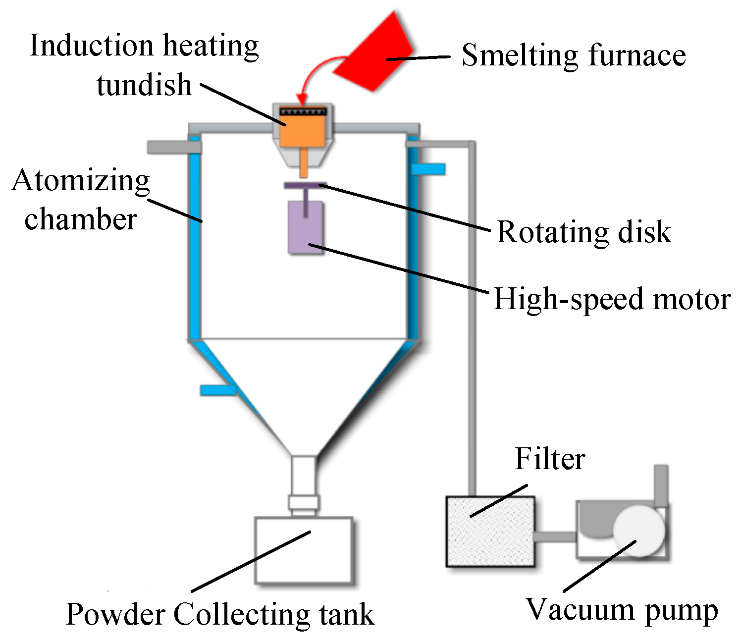
On the basis of the above numerical simulation, the self-developed centrifugal atomization experimental device was used with a flat disk and spherical disk with the same structure and size, as in the numerical simulation. AlSi10Mg, which is the most used material in the field of additive manufacturing, was selected as the research material for experimental verification. After the preparation of the experimental device, the atomization chamber was evacuated and filled with nitrogen after the vacuum degree reached 1 × 10
−2 Pa. The atmosphere preparation was completed if the oxygen content was less than 500 PPm as detected by the online oxygen meter, and then the atomization experiment was started. The method can be described as follows. The AlSi10Mg alloy was added to the melting furnace, we heated the alloy into a melt, and then the molten metal was sent to the induction heating tundish at the upper part of the atomization chamber. The molten metal was delivered to the atomizing rotating disk through the guide tube at the bottom of the induction heating tundish. We adjusted the speed of the high-speed motor to 10,000 rpm and drove the atomization rotating disk to break the molten metal into uniform and stable metal droplets under the action of centrifugal force. After atomization, the atomization disk was removed for photo analysis. The experimental results are shown in
Figure 10. The experimental results show that the diameter of the continuous liquid film boundary of the flat disk is 35 mm, and that of the continuous liquid film boundary of the spherical disk is 42 mm. Although there is a slight error in the simulation results, the diameter of the continuous liquid film boundary of the spherical disk is larger than that of the flat disk, and the liquid filaments produced by the liquid film splitting on the rotating disk are thinner and more numerous, which proves the accuracy of the simulation and its conclusion.
The velocity distribution characteristics of the liquid film on different disk surfaces under the working condition of 10,000 rpm were further analyzed on the basis of the above research. As shown in
Figure 11, the velocity distribution of the molten fluid film on the surface of the flat disk, as well as the radial and tangential velocity distributions, shows that the liquid film velocity, including the radial and tangential velocity of the flat disk, increases with the increasing diameter, and the liquid film gradually accelerates along the radial direction under the action of centrifugation. In other words, the inner circle velocity is relatively small, the outer circle velocity gradually increases, and the maximum velocity is reached at the outer edge. The maximum liquid film velocity is approximately 13.0 m/s, the maximum radial velocity is approximately 5.7 m/s, and the maximum tangential velocity is approximately 11.5 m/s.
The velocity distribution of the liquid film on the surface of the spherical disk is shown in
Figure 12. The velocity distribution of the liquid film, including the radial and tangential velocities, on the spherical disk increases with the increase in the diameter. This means that the velocity of the inner circle is relatively small, that of the outer circle gradually increases, and the velocity reaches the maximum at the outer edge of the disk. The maximum liquid film velocity is approximately 15.5 m/s, the maximum radial velocity is approximately 6.7 m/s, and the maximum tangential velocity is approximately 13.5 m/s. Compared with the flat disk, the liquid film velocity, including the radial and tangential velocity, of the spherical disk is increased by approximately 17–20%. Due to the different forces acting on the fluid film on the surface of the spherical disk, the spherical arc will lead to greater positive pressure between the molten metal and the disk surface, and the liquid film will be subjected to greater friction and relatively less slip, and will have a greater speed. At the same rotational speed, the liquid film on the spherical disk will obtain more energy and achieve a higher energy utilization rate.
3.3. Liquid Film Characteristics with Disk Structure at Different Speeds
The above research involved the spreading and breakage of the liquid film when the molten metal was spread on the disk surface, but it only studied the influence law of different disk shapes under the working condition of 10,000 rpm. Thus, the key factor of the rotating disk speed was not considered. Therefore, the influence of the disk structure on the liquid film characteristics under different rotation-speed conditions is studied. In the previous study, the VOF method was used to capture the gas–liquid interface of aluminum alloy liquid film formation, but the simulation of the thin liquid film distribution formed by high-speed rotation could not be performed by the VOF method. Because the capture of the liquid film by the VOF method requires that the mesh size is less than 1/5 of the thickness of the liquid film, but the thickness of the liquid film formed by the high-speed atomization disk is at the micron level, the application of the VOF method to capture the liquid film requires a large number of grids, which cannot be achieved using the existing resources. In this case, the Fluid Film model of the STAR-CCM+ 2022.1.0 software is used to capture the micron liquid film of the atomizing disk, in order to study the liquid film characteristics on the surface of the rotating disk at a high speed. However, the Fluid Film model cannot be used alone but should be combined with the VOF model. The VOF model should be used first to capture the initial thick liquid film, which gradually becomes thinner as the liquid film expands, and then the Fluid Film model can be used to further capture the later development characteristics of the thin liquid film.
The Fluid Film model was used to simulate and study the characteristics of the liquid film on the surface of the atomizing disk under the rotational speeds of 10,000 rpm, 30,000 rpm, and 60,000 rpm. The obtained calculation results of the liquid film distribution on the surface of the flat disk and the spherical disk are shown in
Figure 13 and
Figure 14. The liquid film distribution mainly consists of a thick liquid film, including a liquid filament (gray), calculated by the VOF method, and a thin liquid film (color) calculated by the Fluid Film method. In
Figure 13 and
Figure 14, it can be seen that the characteristics of the molten metal forming a liquid film on the surface of the rotating disk are basically the same at different rotational speeds. First, the molten metal is poured onto the center of the rotating disk through the diversion nozzle, and a continuous thick liquid film is formed within a certain diameter of the central region (the gray circular region of the cloud image), whose diameter is the boundary diameter of the continuous liquid film, defined above. The outside of the gray circular area is a colored region representing the thickness distribution of the liquid film with different colors. In
Figure 13 and
Figure 14, it can be seen that the liquid film begins to split into liquid bundles when the boundary diameter of the continuous liquid film is exceeded, and when the rotational speed increases from 10,000 rpm to 60,000 rpm, the gray liquid filaments obtained by the VOF method gradually disappear and a liquid filament obtained by the Fluid Film method is gradually formed. The liquid filaments formed by splitting maintain a relatively continuous liquid filament state and move radially in the disk direction, and the motion trajectory is approximately involute.
Based on the analysis and study of the general characteristics of the liquid film on the surface of the atomizing disk at different speeds, the different characteristics of the liquid film formed by different disk shapes at different speeds were further analyzed. In
Figure 13 and
Figure 14, the continuous liquid film boundary diameters of different atomizing disks at different rotational speeds show that the continuous liquid film boundary diameter widths of flat and spherical disks gradually decrease with increases in rotational speed, and the continuous liquid film boundary diameter widths of the flat disk decrease by 28.7%, from 36.5 mm to 26 mm, when the rotational speed increases from 10,000 rpm to 30,000 rpm. The continuous liquid film boundary diameter width of the spherical disk is reduced by 32.9%, from 47 mm to 31.5 mm. When the rotational speed increases from 30,000 rpm to 60,000 rpm, the boundary diameter width of the continuous liquid film of the flat disk decreases from 26 mm to 19 mm, by approximately 25.9%, and the boundary diameter width of the continuous liquid film of the spherical disk decreases from 31.5 mm to 24.5 mm, by approximately 22.2%. By analyzing the above data, it can be concluded that the variation amplitude of the boundary diameter of different disk-shaped continuous liquid films is not notably different under the same speed variation amplitude, and the difference in the variation amplitude is less than 5%. Moreover, in
Figure 15, the boundary diameters of the continuous liquid films on the flat and spherical disks at different speeds can be seen to decrease with increasing speed, and the slope and change law of the curve are almost the same, further proving that the boundary diameters of different continuous liquid films with different disk shapes are almost the same at the same speed. Therefore, it is proven that the continuous liquid film boundary diameter is most affected by the speed of the atomizing disk, while it is less affected by the disk shape. However, it can also be seen from
Figure 15 that, under the same working conditions, the overall boundary diameter of the continuous liquid film of the spherical disk is approximately 21–29% larger than that of the flat disk, i.e., the shape of the disk plays a decisive role in the overall boundary diameter of the continuous liquid film, which is consistent with the characteristics of the liquid film on the flat disk and the spherical disk obtained by the VOF method. The accuracy of the result is proven.
As for the distribution clouds of the liquid film on the surfaces of different disk shapes at different speeds shown in
Figure 13 and
Figure 14, the comparative analysis shows that, compared with the flat disk, the thickness of the liquid film on the surface of the spherical disk is relatively uniform, and the liquid filaments are finer and greater in number. After further processing of the simulation results, the average liquid film thickness data for different speeds were obtained, as shown in
Figure 16. It can be seen from
Figure 16 that the average liquid film thickness on the surfaces of the flat and spherical disks gradually decreases with the increase in the rotational speed. When the rotational speed increases from 10,000 rpm to 30,000 rpm, the average thickness of the liquid film on the surface of the flat disk decreases from 14 μm to 13 μm, and the average thickness of the liquid film on the surface of the spherical disk decreases from 9.8 μm to 9.1 μm. The reduction amplitudes of the two disk shapes are almost the same, decreasing by approximately 7%. When the rotation speed increases from 30,000 rpm to 60,000 rpm, the average thickness of the liquid film on the surface of the flat disk decreases from 13 μm to 8.7 μm, with a decrease of 33.1%, and that of the spherical disk decreases from 9.1 μm to 8.4 μm, with a decrease of approximately 7.7%. The reduction amplitudes of the two disk shapes are quite different. Therefore, in general, compared with the flat disk, the liquid film thickness on the spherical disk decreases more slowly and stably with the increase in the rotational speed. At the same time, it can be seen from
Figure 16 that the average liquid film thickness on the spherical disk is thinner under the same working conditions. Moreover, the thickness difference in the liquid film on the two disk-shaped surfaces decreases from 4.2 μm to 0.3 μm as the rotational speed increases from 10,000 rpm to 60,000 rpm. In other words, the influence of the disk shape on the thickness of the liquid film becomes smaller when the rotational speed increases to a certain range, but the distribution uniformity and stability of the liquid film are still mainly affected by the atomizing disk shape.
3.4. Study of the Evolution Law of Molten Metal Atomization into Droplets on the Surface of Rotating Disk
The above numerical simulation was used to systematically study the motion state of the liquid film on the surfaces of different disk shapes and the distribution characteristics of the liquid film on the surface of the rotating disk at different rotational speeds. However, the law by which the liquid film breaks and evolves into liquid droplets is still unclear. Therefore, the evolution process of molten metal atomization into droplets in the rotating disk is studied in this section.
The geometric model and specific structural parameters of the simulation model used in this part of the research were further simplified on the basis of the previous model. In order to capture the whole process of the liquid film on the surface of the rotating disk, the liquid filaments formed by fracturing, and their further breakage into droplets, as well as to reduce the calculation amount, only the liquid injection port and atomization disk were retained in the model, and the atomization disk was selected as a flat disk with its diameter reduced to 50 mm. Other components were also simplified and omitted. In order to highlight the evolution law of atomization crushing, the atomization flow rate was increased and the inlet liquid flow rate was set to 5.0 m/s, while the atomization speed was reduced to 2000 rpm. By increasing the flow rate and reducing the speed, the liquid film on the surface of the atomization disk is made to become thicker and easier to capture. At the same time, the modified liquid material is selected as the research object, and its material performance parameters are shown in
Table 3, exhibiting the characteristics of high viscosity and large surface tension. Thus, it is easier to form a liquid filament state during atomization. Under the condition of high viscosity, more regular changes, such as necking, fracture, and spheroidization, will occur, and the formation and evolution phenomenon will be more obvious. The simulation was divided into two parts, the small-angle fluid domain and the whole-circle fluid domain, in which we studied the evolution law of the single liquid filament and the whole disk liquid film spreading and splitting into liquid filaments and breaking into liquid droplets. The advantage of small-angle domain (angle 10°) calculation is that the grid is finer and the result is of higher precision.
For the small-angle fluid domain (angle 10°) and the whole-circle fluid domain, we adopted the cutting body mesh; the mesh size was 1.2 mm, and the atomization disk, the inlet area, and the disk edge area were encrypted with a mesh size of 0.0625 mm. To accurately capture the air–liquid interface and particles, the number of meshes was 1.72 million and 32.69 million, respectively. The mesh model is shown in
Figure 17 and
Figure 18, and its boundary conditions are shown in
Figure 19.
The results obtained from the above simulation research, which aimed to capture the liquid film on the surface of the rotating disk, and the liquid film splitting to form liquid filaments and finally breaking into droplets, are shown in
Figure 20 and
Figure 21. According to the cloud image of the evolution process of the separation and fragmentation of the liquid film in the small-angle atomization of the rotating disk in
Figure 20, it can be seen that the liquid in the small-angle fluid domain is poured onto the surface of the rotating disk and gradually spread on the surface of the atomization disk to form a continuous liquid film with a free surface. When the liquid film spreads and moves a certain distance, local bulges begin to form and the initial shape of the liquid filament is formed, as shown in
Figure 20b; t = 2.2 s. After the initial liquid filament is formed, the liquid filament gradually expands and extends, and the diameter of the tip gradually shrinks. At this time, interface stress (such as surface tension, etc.) has a significant impact on the liquid filament, and the tip begins to shrink, as shown in
Figure 20c; t = 2.4 s. Because of the influence of surface tension, the tip of the liquid filament shrinks. The R–T interface becomes unstable due to the interaction of the gas–liquid two-phase interface, and an interfacial wave along the liquid column is generated [
34]. The disturbance of the interfacial wave is formed along the tip and spreads upstream. The tip absorbs upstream fluid through contraction, and it begins to grow and forms large droplets at the end of the liquid filament, as shown in
Figure 20d; t = 2.6 s. When the diameter of the necking area of the liquid filament shrinks to a certain extent, the tip separates from the main liquid filament to form discrete droplets under the influence of circumferential surface tension, as shown in
Figure 20e; t = 2.8 s. After the tip of the liquid filament is broken and formed into small droplets, the liquid flow at the back of the liquid filament is continuously supplied, and the tip droplets are continuously broken and dispersed to form atomized droplets. The atomized droplets move away from the atomization zone along the movement track and gradually evolve into spherical droplets under the action of surface tension; finally, spheroidal droplets are formed, as shown in
Figure 20f; t = 3.2 s.
The evolution processes of atomization to form a single liquid filament and breakage to form a droplet have been analyzed. The global motion characteristics of the liquid film on the rotating disk and the evolution process of the separation liquid filament breaking into droplets are shown in
Figure 21. Based on the cloud image of the evolution process of global liquid film formation, separation, and crushing in
Figure 21, it can be seen that the liquid is poured from the nozzle onto the rotating disk to form a circular, continuous liquid film at the center of the disk, as shown in
Figure 21a; t = 0.3 s. With the gradual growth of the liquid film, the continuous liquid film gradually expands on all sides and forms a local bulge at the front end of the liquid film, as shown in
Figure 21b; t = 1.2 s. The thickness of the local liquid film at the convex vertex will gradually increase, and the adjacent area will become thinner. The mass of the local liquid film and the centrifugal force will gradually increase. Finally, the liquid film will break at the local liquid film under the condition of insufficient surface tension, and it will finally separate to form a liquid filament, as shown in
Figure 21c; t = 2.4 s. At the initial stage of liquid filament formation, the roots of the liquid filament are thicker at the edge of the disk, and they are gradually narrowed and refined with the evolution of the liquid filament, as shown in
Figure 21d; t = 3.6 s. With the destruction of the surface tension at the roots of the liquid filament, another liquid filament is produced and gradually extends and becomes longer under the centrifugal force, as shown in
Figure 21e; t = 4.8 s. With the further development of the liquid film and liquid filaments, the number of liquid filaments gradually increases, as shown in
Figure 21f; t = 6.0 s. The liquid filament moving away from the disk edge does not break immediately but extends radially outward to a certain distance, and a liquid filament flow will be formed on the disk edge, as shown in
Figure 21g; t = 8.0 s. After the liquid filament is formed, it is first stretched to the limit length to maintain the same length, and the diameter of the tip is gradually reduced. Moreover, the liquid filament is unstable at the R–T interface and generates an interface wave disturbance along the direction of the liquid filament, and the end of the liquid filament breaks and forms atomized droplets, as shown in
Figure 21h; t = 10.0 s. The radial velocity of the liquid filament is very small compared with the tangential velocity of the liquid filament at the edge of the rotating disk, and the running track of the liquid filament is similar to an involute line. Droplets formed by atomization will fly and disperse along the original movement track and gradually evolve into a ball, as shown in
Figure 21i; t = 15.0 s.


