Article

Water Flow Boiling in Micro/Mini Channels Using Volume of Fluid Model

by
Muhammad Umer Khan Mughal
1,
Khalid Waheed
1,
Muhammad Imran Sadiq
2,
Altaf Hossain Molla
2,
Zambri Harun
2,* and
Amin Etminan
3,*
1
Department of Mechanical Engineering, Pakistan Institute of Engineering and Applied Sciences (PIEAS), Islamabad 46000, Pakistan
2
Department of Mechanical and Manufacturing Engineering, Faculty of Engineering and Built Environment, Universiti Kebangsaan Malaysia (UKM), Bangi 43600, Malaysia
3
Department of Mechanical Engineering, Faculty of Engineering and Applied Science, Memorial University of Newfoundland (MUN), St. John’s, NL A1B 3X5, Canada
*
Authors to whom correspondence should be addressed.
Appl. Sci. 2024, 14(2), 759; https://doi.org/10.3390/app14020759
Submission received: 26 November 2023 / Revised: 31 December 2023 / Accepted: 3 January 2024 / Published: 16 January 2024
(This article belongs to the Section Applied Thermal Engineering)

Abstract

:
Recent advancements in computational fluid dynamics (CFD) have triggered research in the field of heat exchangers. Driven by the need to decrease the size of heat exchangers, many researchers have exploited the higher heat transfer achieved by replacing single-phase flow systems with boiling counterparts. The concept of using mini-channels to provide compact heat exchangers while maintaining heat transfer performance is relatively new. A minimal number of researchers have reported simulations of water-steam systems in mini-channels. This paper presents a numerical study of the heat transfer performance (HTP) of mini channels in a water-steam system using the volume of fluid (VOF) model coupled with the Lee phase change model on commercial CFD software ANSYS. The numerical model consisted of a 1   mm   ×   1.5   mm   ×   52   mm channel with boundary conditions: top adiabatic; constant heat flux at the bottom surface; left/right periodic; mass flow inlet and pressure outlet. A mesh independence study was carried out for the proposed model, and simulations were validated against the experimental results of heat transfer versus vapor quality for a wide range of mass and heat fluxes. The VOF model best predicts experimental HTC at high mass fluxes, although the results at low mass fluxes were predicted with reasonable accuracy. Based on the agreement of numerical and numerical results, the VOF model turned out to be a promising candidate for designing compact micro/mini channel heat exchangers.

1. Introduction

The conventional heat dissipation systems relied on single-phase flow, based on natural and forced convection, to exchange heat. Single-phase heat transfer coefficients (HTC) were limited by power and system size requirements. Further technological advancement required light-weight and compact thermal systems. As a result, two-phase flow boiling (FB) systems, such as shell and tube heat exchangers, boilers, and helical coil steam generators, were designed. These two-phase systems were based on high HTC dominated by the nucleate boiling (NB) mechanism at low-volume fractions and convection currents generated by the mist flow regime at high-volume fractions.
The higher heat transfer dictated by two-phase flow has numerous applications in the nuclear and aerospace industries. Silvi et al. [1] used the VOF model to investigate FB in water in a boiling water reactor (BWR). Various flow regimes, including nucleate boiling, transition boiling, flow boiling, and complete local dry-out, were simulated inside the circular rod assembly of BWR, and HTC was worked out at 30 bar. Konishi et al. [2] reviewed the literature on FB and condensation under reduced gravity to explore their viability for aerospace applications. In lieu of developing energy-efficient air/space vehicles, Wang et al. [3] reviewed aerospace-oriented spray cooling—that employs boiling—and made recommendations for incorporating gas-atomized spray cooling. A study in [4] reviewed pool boiling (PB) and FB of dielectric fluids with an emphasis on mitigating the heat dissipation requirements of electrical equipment. The effect of surface enhancement on the HTP of dielectric fluid was also considered. Liu et al. [5] elucidated FB of ammonium dinitramide using VOF coupled with the Lee phase change model to design electronic spacecraft thrusters.
Researchers have also employed the VOF model to study FB of refrigerants to design efficient cooling systems. Using the VOF model along with the level set (LS) scheme, the authors in [6] defined a criterion for estimating bubble departure diameter during FB of refrigerant R314a. Hu et al. [7] similarly investigated HTC and flow instabilities during FB of R314a using VOF. They concluded that a discrete heat source was better at suppressing the instability than a continuous heat source. The VOF was also used by Fsadni et al. [8] to simulate a three-phase FB consisting of water liquid, water arising in gas from the liquid phase, and embedded nanoparticles such as aluminum oxide, and titanium oxide, separately. The addition of nanoparticles enhanced heat transfer.
The helical coil heat exchangers had a compact design, ease of manufacture, and high heat transfer efficiency. All these advantages render helical coil heat exchangers promising candidates for the nuclear and power generation industries [9]. Owhadi et al. [9] were the first to experimentally study FB in helical coil heat exchangers. It was reported that forced convection evaporation was the dominant heat transfer mechanism (HTM) at high vapor quality, while the NB mechanism was present at low vapor quality. The experimental data showed good agreement with FB correlation for straight tubes proposed by Chen [10].
Steiner et al. [11] presented a correlation for FB in large-diameter vertical tubes. The correlation was suitable for straight vertical tubes in a system with a pressure lower than 7 MPa. Researchers [9,10] separately carried out FB experiments in helical coil tubes using system pressure over 3.5 MPa. At low mass flux and high heat flux, the helical tubes were covered by regions of vapor quality lower than 0.1, and NB was the main heat dissipation mechanism. Both researchers reported good agreement with the correlation for straight vertical tubes proposed by [12].
Using helically coiled tubes heated by high-temperature water, Tanaka [13] reported experiments spanning an extensive range of data points: steam quality in the range of 0–1, system pressure 0.5–2.1 MPa, heat flux varying from 151–348 kW/m2, and mass fluxes in the range of 161–486 kg/(m2.s). Supporting the observations made by [10], forced convection was the main HTM, and the HTC was correlated for the abovementioned range of experimental conditions. Guo et al. [14] researched boiling HTC in helical coils by varying their orientation axially. The analysis covered three regimes: NB, forced convection, and the post-dry-out. It was concluded that, with the exception of the post-dry-out region, the HTC was a strong function of system pressure, and as a result, the presented correlation showed good alignment with experimental data with an accuracy of ±15%.
Zhao et al. [15] observed that NB and convection mechanisms played equal roles in heat transfer through their experimental investigation of small-diameter helical tubes. Their study was conducted for tube diameters less than 12 mm and steam quality greater than 0.1. A correlation for HTC based on the Lockhart-Martinelli parameter was proposed with an accuracy of ±12%. In a similar investigation on small-diameter tubes, Yi et al. [16] proposed that, as opposed to straight tubes, the pulsation and secondary flow induced by bubbly flow regimes in helical tubes enhanced heat transfer. Their correlations for HTC in pre-dry-out and post-dry-out regimes showed great accuracy with experimental data.
The availability of advanced manufacturing techniques, such as surface mechanical machining, chemical etching, surface coating techniques, and micro-electro-mechanical system techniques, allowed the preparation of microchannels for two-phase boiling heat transfer. These microchannels range in size from several microns to a few millimeters and provide very high surface area-to-volume ratios. Chen et al. [17] performed PB experiments on rectangular grooves with sizes in hundreds of microns that were prepared by CNC machining on copper plates. The HTC was presented as a function of the capillary effect produced by microgrooves. Hendricks et al. [18] manufactured nanostructured surfaces on copper and aluminum using the micro-reactor-assisted nanomaterial deposition (MAND) technique, with a surface roughness of 80–6000 nm and a pore size of 50–100 nm. The HTC in NB and critical heat flux (CHF) regimes were studied on these channels using water as the working fluid. Kim et al. [19] concluded that, as compared to flat surfaces, the increase in heat transfer could be attributed to changes in bubble nucleation pattern, enlargement of the available surface area, and mechanism of bubble growth through their experimental investigation of micro- and nanostructured surfaces on silicon wafers. Ahn et al. [20] manufactured micro- and nanostructured surfaces on zircaloy-4 tubes using chemical etching and performed water PB experiments.
The empirical correlations have inherent shortcomings; they are valid for one or two fluids, specific geometrical patterns, and flow patterns. Even if a correlation is valid for a wide range of conditions, it requires a large set of data points, making the experimentation very costly and compromising its efficiency for a specific problem. To tackle these problems, researchers used CFD to solve boiling HTM. Most of the research on boiling heat transfer was focused on NB and film boiling HTM. The FB heat transfer phenomenon is very complicated; it depends on various parameters such as flow patterns in the channel (bubble, slug, annular, mist, and pure vapor), channel orientation, channel size, inlet temperature, inlet quality, and channel pressure drop. As a result, very few studies have reported CFD of FB, specifically in mini-channels. Etminan et al. [21] recently conducted a comprehensive review of the hydrodynamics of Taylor flow, showing different flow patterns. The available correlations in the literature for prediction flow pattern transitions have been collected and presented in [22].
Mukherjee et al. [22] coupled the LS method for tracking volume fraction with an energy jump condition for the phase change to investigate vapor bubble growth in a 200 µm square microchannel. Using the constant contact angle assumption, it was reckoned that the bubble departure rate accelerated with the degree of superheat and deteriorated with increasing mass flux. Mukherjee et al. [23] employed the same model to predict that for micro-channels with inlet flow constriction, bubble growth decreased and the constriction increased flow reversal. Lee et al. [24] also used the LS method, coupled with energy jump conditions for mass transfer and a simplified model for micro-layer evaporation, to reproduce the water bubble growth rate in micro-channels as predicted by experiments. The heat transfer increased for a channel size smaller than the bubble departure diameter. A CFD study of two-phase jet impingement was carried out by the authors of [25,26]. Hassan et al. [27] and Faris et al. [28] used nanofluids for heat transfer enhancement.
Using a new method called “pseudo boiling”, Zu et al. [29] investigated FB of water in micro-channels using the VOF model. In this method, water bubbles were introduced from small pores on the wall. By matching the bubble injection and growth rate with experimental data, they could predict bubble distortion and trajectory. Similarly, Garoosi [30] improved the efficiency of interface capture in VOF by adopting the total variation diminishing (TVD) flux-limiter algorithm in conservation equations. By incorporating the correlation of interfacial mass and energy transfer for different stages of boiling, Zhuan et al. [31] solved the VOF model for water in microchannels, which showed good agreement with experimental results. Mulbah et al. [32] addressed challenges while using the VOF model to capture bubble interfacial departure and proposed a criterion for selecting the proper VOF method. Zhao et al. [33] incorporated accurate jump conditions for heat and mass transfer across the interface, thus providing better large eddy simulation (LES) with VOF. They also benchmarked their model for the Leidenfrost phenomenon. Zhang et al. [34] proposed a novel mixture model that was computationally less expensive than the VOF model and was used to simulate subcooled FB in microchannels. Vaishnavi et al. [35] studied bubble generation using the VOF water channel by injecting air through a 1 mm-diameter hole. Lin et al. [36] considered different geometries—convergent, divergent, and normal microtubes—for their effect on water FB in terms of pressure drop. VOF and a sharp interface capturing scheme were employed for the direct numerical simulation of the evaporation and condensation [37,38]. The capability of VOF in phase interface prediction was carefully studied by Etminan et al. [39] in microchannels with a diameter of 250 microns. Interface modeling using VOF was also performed by Tang et al. [40] and Sadiq et al. [41].
In the subcooled boiling regime, the core consists of subcooled liquid, and the vapor bubbles formed at the heated wall condense as they detach from the wall and reach the subcooled core. Zhuan et al. [42] performed CFD of subcooled boiling water using the VOF model coupled with condensation correlation provided by Warrier et al. [43]. The computational flow regimes matched the experimental flow regimes, and the predicted HTC was acceptable. A similar study using the VOF model was performed by Pan et al. [44], in which phase change was based on Nusselt, Reynolds, Prandtl, and Fourier numbers. They reproduced the bubble size and deformation obtained from experiments. Unlike other researchers, Wu et al. [45] used the Eulerian phased change model to solve conservation equations for each phase separately and coupled them with pressure and interphase exchange coefficients. The working fluid (R141b) entered the horizontal tube and was subcooled at 30 °C. The results agreed well with the experimental data. Through their research on the FB of water in vertical vapor-vented micro-channels, using the VOF model in Fluent, Fang et al. [46] showed that vapor-vented micro-channels had a lower pressure drop than non-vapor-vented channels up to the critical value (defined as the value where vapor generation exceeds vapor venting rate). Chen et al. [47] numerically investigated CHF during subcooled FB inside vertical mini-channels and proposed that as the length of the dry patch generated by CHF increased, the heat transfer deteriorated. Rabhi et al. [48] separately used CFD to study the onset of nucleate boiling (ONB) in vertical mini-channels and proposed correlations to better predict ONB that are valid for a range of flow conditions. Jain et al. [49] proposed a one-dimensional numerical to incorporate the effect of pressure fluctuations on HTC for FB inside rectangular microchannels. Additionally, heat transfer under flow reversals and instability caused by pressure fluctuations are also considered. Chen et al. [50] elucidated the microlayer evaporation phenomenon for FB inside mini-channels and demonstrated various heat transfer modes during microlayer evaporation.
Wang et al. [51] carried out a numerical study of a two-phase system consisting of oil-water emulsion and superposed both electric field and flow to study the effect of electric field on oil-water separation. Similarly, Qi et al. [52] employed a numerical approach to study two-phase oil-water separation in oilfield production. Bard et al. [53] performed Fb experiments on 12 working fluids for a range of flow conditions and then employed a machine learning approach to predict HTC in micro/mini-channels.
Liu et al. [54] performed an experimental study on the thermal hydraulics of straight mini-channels and micro-channels chemically etched on brass plates. The brass plate was heated by cartridge heaters, and thermos-couples were used to find steam temperatures. The HTC was plotted against local quality for both channel sizes. The results showed that micro-channels had a higher HTC than mini-channels for constant mass flow rate and heat flux. Experimentation for the occurrence of three types of instabilities in micro-channels: Ledinbegg instability, pressure-drop oscillation, and density-wave oscillation, was carried out by Shin et al. [55]. They proposed that the instability occurrence could be minimized by increasing the form loss coefficient K at the inlet.
There is a lack of research literature on FB of water, and few researchers have investigated FB of water in mini-channels. A computational study for FB of water using parallel mini-channels under a wide range of mass flux and heat flux has not yet been reported. The results from experimental data have to extrapolate temperature at the solid-liquid interface, while the numerical study could cater to the lack of data at the interface, thus providing designers with greater flexibility. Therefore, this paper presents a computational study of FB in parallel mini-channels using the VOF model coupled with the Lee phase change model in the commercial CFD software ANSYS Fluent 15. The computational model consisted of a single rectangular mini-channel of 1   mm   ×   1.5   mm   ×   52   mm . The effect of parallel channels was incorporated by using periodic boundary conditions on side walls; other boundary conditions included mass flow inlet, pressure outlet, adiabatic wall at the top surface, and constant wall heat flux at the bottom surface. A mesh independence study was carried out for the proposed model, and simulations were validated against the results of heat transfer versus vapor quality, as reported by Liu et al. [54], for an extensive range of mass and heat fluxes. The numerical results demonstrated good agreement with the experimental study, and the maximum error was within ±16%. This research proposes a VOF model for modeling two-phase flows occurring in steam generators, thus making them compact and increasing their efficacy.

2. Numerical Solution

2.1. Governing Equations

The experimental setup in the reference [54] consisted of 20 parallel mini-channels with dimensions of 1   mm   ×   1.5   mm   ×   52   mm . The mini-channels were fabricated by electric discharge machining (EDM) on brass blocks. The top surface of the brass block was insulated by silicon, and the bottom surface was heated by cartridge heaters. The numerical study of 20 mini-channels would have been very expensive computationally. To simplify the numerical model, the domain was reduced to a single mini-channel by using periodic boundary conditions. As shown in Figure 1, the boundary conditions of the 3D model consisted of top-side adiabatic, constant heat flux at the bottom, and periodic walls at both sides.
The VOF model is the most common method used to simulate FB. It is an inherently conservative method that captures the interface between two phases by assigning a color function α to each phase. The value of α varies from 0 to 1, where 0 means the cell is filled by one phase and 1 means the cell is filled by another phase. A piecewise linear interface capture (PLIC) scheme was used with the VOF method to capture the interface. The PLIC captures the interface as a straight line whose direction is given by a normal vector. The normal vector is oriented by interrogating the volume fraction of neighboring cells, and its direction is so selected that the volume fraction of cells is maintained [56]. The conservation equations are solved as follows [56]:
Continuity:
1 ρ q t α q ρ q + · α q ρ q v = S q + p = 1 n m l v ˙ m v l ˙
where primary phase volume is computed based on the following:
q = 1 n α q = 1
where α q is the volume fraction of qth phase, S q is a source term for each phase and is usually zero, m l v ˙ is the mass transfer rate from phase l to phase v and m v l ˙ is the mass transfer rate from phase v to phase l . The Lee phase change model was selected to simulate evaporation. The phase change in the Lee model is directly proportional to the deviation from the saturation temperature, T s a t . It is assumed that phase change occurs at constant pressure- the temperature of phases and interface is maintained at T s a t . Using the Lee model [57], the mass transfer rates are given as follows:
If T l > T s a t (evaporation),
m l v ˙ = r i α l ρ l T l T s a t T s a t
If T l < T s a t (condensation),
m v l ˙ = r i α v ρ v T s a t T v T s a t
The coefficient r i is called the mass transfer intensity factor and has the unit of s−1. There is a significant variation in the choice of r i value. Researchers have used an extensive range of r i values, ranging from 0.1 to 1   ×   10 7 s−1, to fine-tune the deviation of T s a t , according to their experimental data.
Momentum:
t ρ v + · ρ v v = p + · μ v + v T + ρ g + F
where ρ is the mixture density, and μ is the mixture viscosity given by the following:
ρ = α l ρ l + α v ρ v
μ = μ l ρ l + μ v ρ v
Energy:
t ρ E + · v ρ E + p = · k e T + S e ,
where S e is the energy source term, and k e is the effective thermal conductivity of the mixture given by the following:
k e = α l k l + α v k v
E is the specific internal energy given by the following:
E = α v ρ v E v + α l ρ l E l α l ρ l + α v ρ v
where E v and E l are determined as follows:
E i = c v , i ( T T s a t ) ,   i = v o r l
where c v is the constant specific heat and T s a t is the saturation temperature.
The source term for the energy equation is given by the following:
S e = h l v S l
where h l v is the latent heat of vaporization of water at a given temperature and pressure.
The thermal conductivity equation in the solid region is given by the following:
λ T = 0
where λ is the thermal conductivity of the solid wall.
The overall HTC was worked out based on local wall temperatures and heat flux. To calculate the local parameters horizontal lines were drawn at various lengths along the channel, and quantities were line averaged as follows:
T b = 0 l T b x . d x
T w = 0 l T w x . d x
q = 0 l q x . d x
h = q T w T b
where q is wall heat flux, T w is wall temperature and T b is near wall temperature.
The quality at a given line segment was evaluated using an area-weighted average as follows:
x = 1 A x . d A

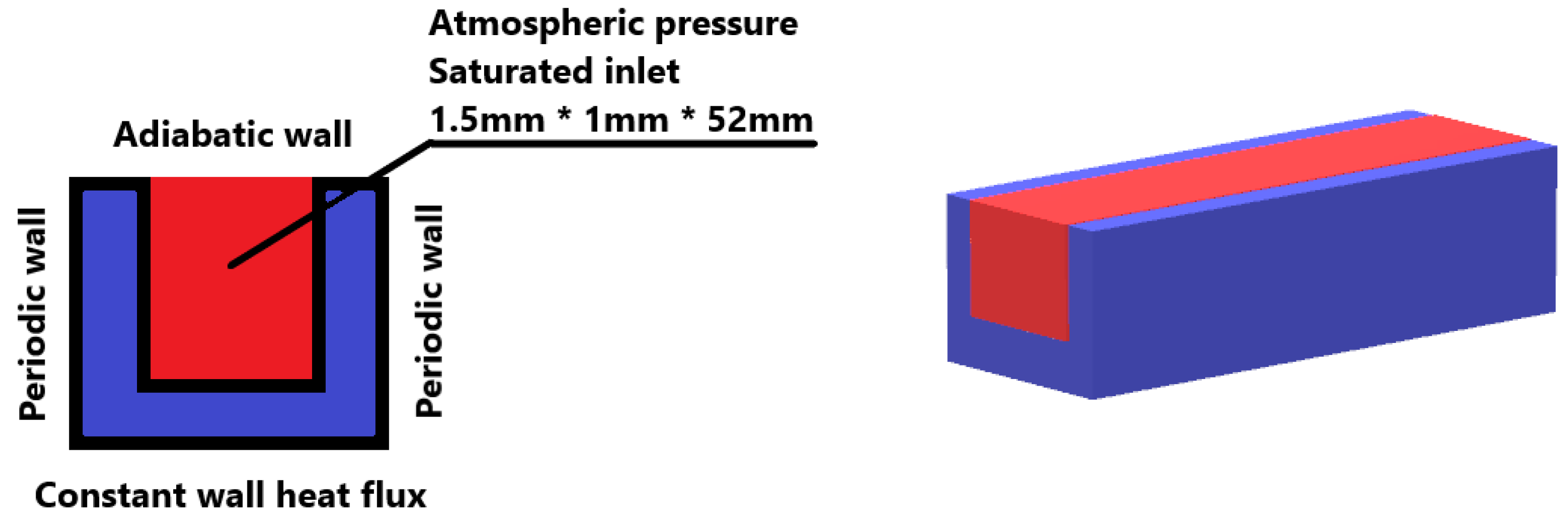
2.2. Computational Model

The numerical analysis for FB in mini-channels was performed by varying the channel mass flux and bottom surface heat flux. The mass flux was changed from 11.09 to 44.36 kg/(m2.s), and the heat flux was varied from 5 to 50 W/cm2, similar to the reference paper by Liu et al. [54].
The flow chart of our research methodology is shown in Figure 2. After the fluid flow geometry was constructed, meshing was done using ANSYS Mesher. Thereafter, boundary conditions were applied, and the model was solved. The mesh was subsequently refined until the values of line average HTC and area average quality converged. Then, the model was benchmarked against the experimental data, and finally, the viability of the computational model was corroborated.

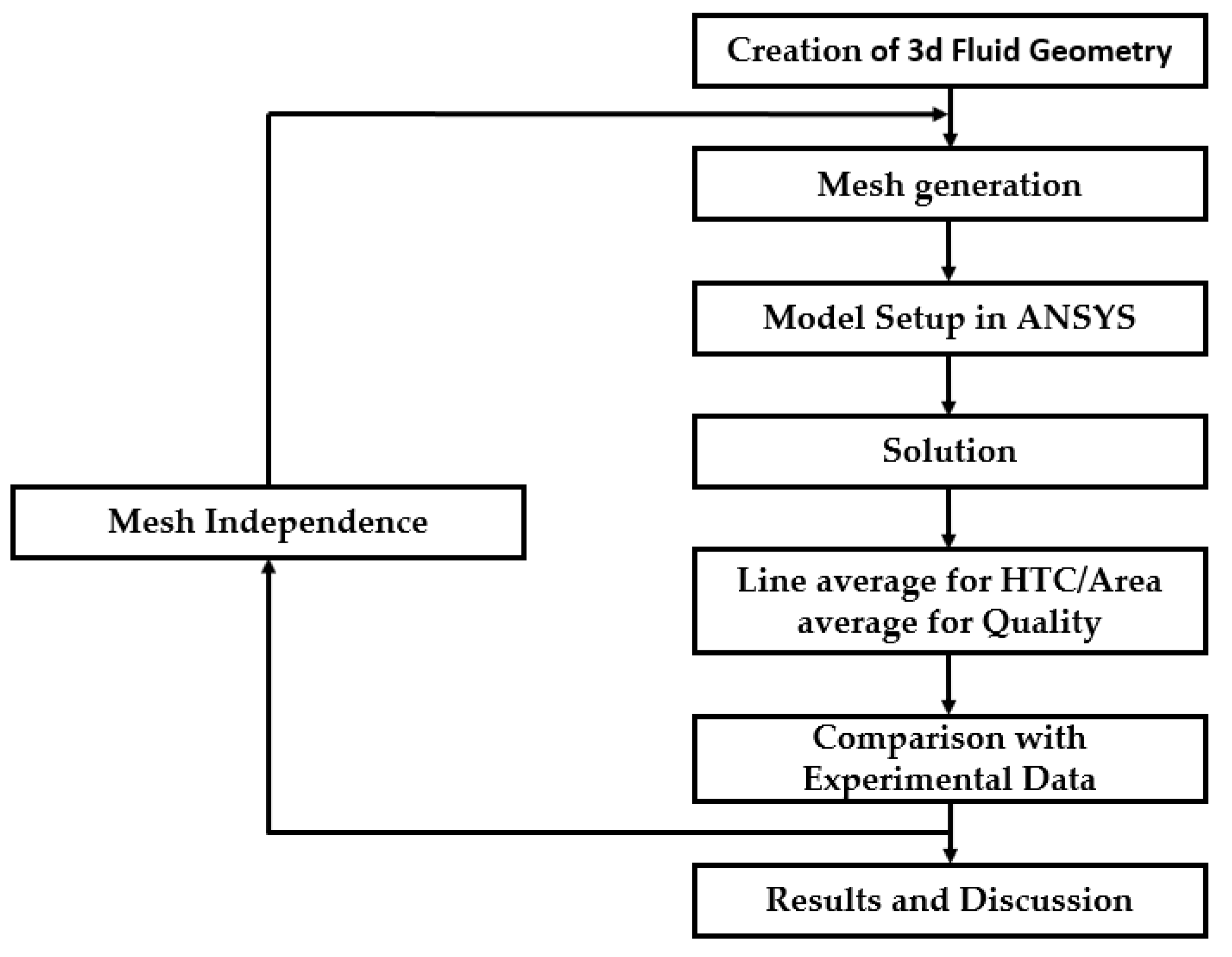
2.3. Mesh Independence Study

The computational domain was meshed with hexahedral elements using the ANSYS Fluent built-in mesh generator. The generated mesh had an element quality of 0.9. The mesh independence was done using the same variables as mentioned in the reference [54]. Local HTC was plotted against vapor fraction, and a mesh independence study was performed at mesh counts of 0.8, 1.2, 1.8, 2.1, and 2.5 million. Mesh independence was reached at 2.5 million elements, as shown in Figure 3. As seen from Figure 3, the difference between the results of tetra mesh with 2.1 and 2.5 million elements was 1.2%. So, a hexahedral mesh with 2.1 million elements was used in the numerical simulations.

3. Results and Discussion

At a low mass flux of 11.09 kg/(m2.s), the simulation results follow the experimental data, but the numerical model predicts a linear variation of HTC with vapor quality. As seen from Figure 4 and Figure 5, the experimental HTC is low at the start of NB and increases as the bubble density increases, but the numerical HTC shows a linear decrease. This deviation could be attributed to the Lee phase change model [57]; it predicts mass transfer depending upon the linear deviation of the bulk temperature from the saturation temperature. The deviation from experimental results decreases as the heat flux increases at the same mass flux.
The initial hump in HTC is because during nucleate boiling, the HTC increases owing to very small droplets evaporating from the surface of the channel. But as the fluid moves along the channel, the bubbles elongate in size, changing the flow pattern from minute-sized bubbles to annals or slugs of vapor covering most of the channels, and therefore, the HTC drops both in numerical and experimental data [58].
The numerical results come closer to the experimental data at a moderately higher mass flux of 22.18 kg/(m2.s). The initial deviation that was seen at low mass fluxes is very small at this mass flux. As seen from Figure 6 and Figure 7, the numerical curves follow the experimental curve very closely at the start of the NB regime. Furthermore, at high bottom heat flux, the numerical results under-predict HTC. This deviation increases as the heat flux increases. The HTC in FB depends on the combined effect of nucleate and convection boiling mechanisms, as suggested by Liu et al. [54]. At high vapor quality, convection heat transfer dominates, and HTC deteriorates compared to the NB regime.
At a further higher mass flux of 33.27 kg/(m2.s), the model shows very good overlap with the experimental results. At this mass flux, the experimental results show a linear trend of HTC with vapor quality. This is the region where the Lee model starts to predict experimental results very well. The maximum error comes down to +9%. Although at low heat flux, a small deviation is seen in the NB regime, this deviation vanishes at higher heat fluxes. The results are shown in Figure 8 and Figure 9. The under-prediction of HTC at moderate mass flux is minimal at high mass flux.
At the highest mass flux of 44.36 kg/(m2.s), the HTC follows the same general trend. The HTC deviates at low heat flux in the NB regime, but at high heat flux, the HTC exactly overlaps the experimental data. The maximum error in this case is further lower, at +7%. As shown in Figure 10 and Figure 11, the Lee model best predicts the HTC at the highest mass flux. Moreover, the deviation at low heat flux in the present case is not pronounced as much as it was for the case of lower mass flux (for the same heat flux).

4. Conclusions

There was a paucity of literature on FB of water in parallel micro/mini channels. This paper investigated the VOF model built into ANSYS Fluent to predict the heat transfer performance of water FB in parallel mini-channels. The suggested model was validated for the range of mass flux from 11.09–44.36 kg/(m2.s) and heat flux from 5–50 W/cm2 (using experimental data of Liu et al. [54]). The results showed that the proposed model agreed well with the experimental data. The maximum deviation from the experimental data was +16%, and the overall error was ±10%. The following were the main findings:
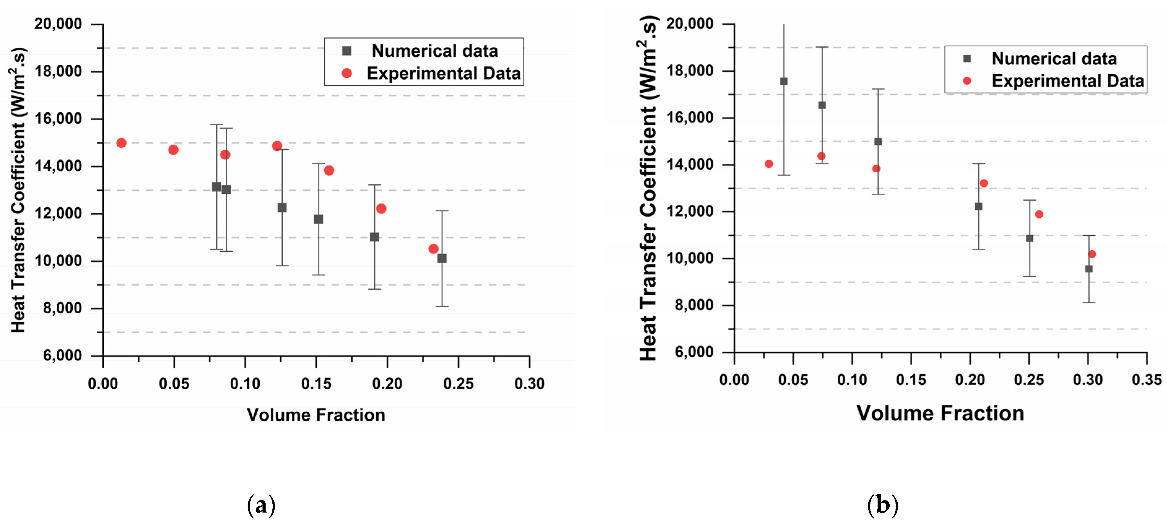
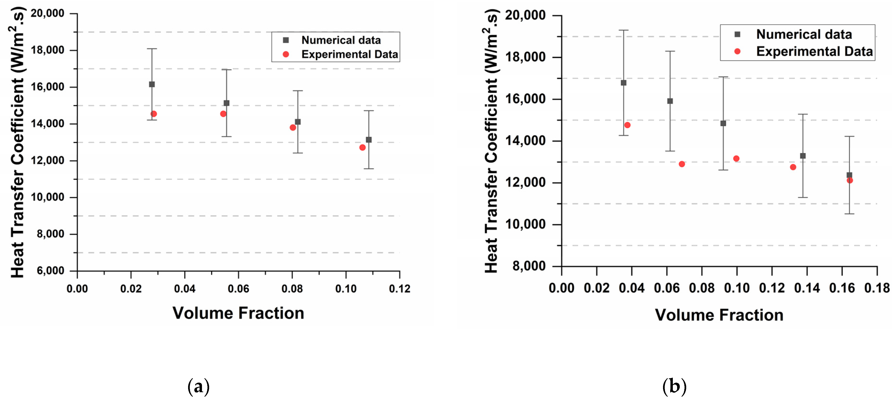
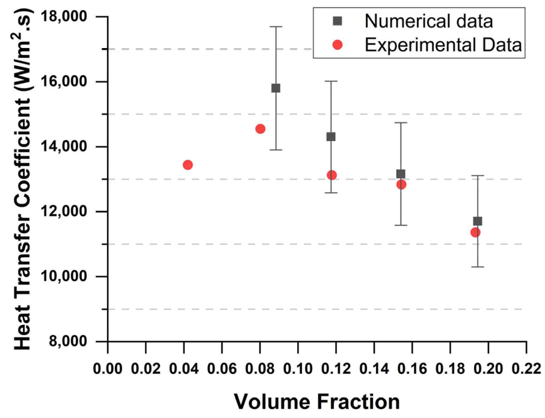
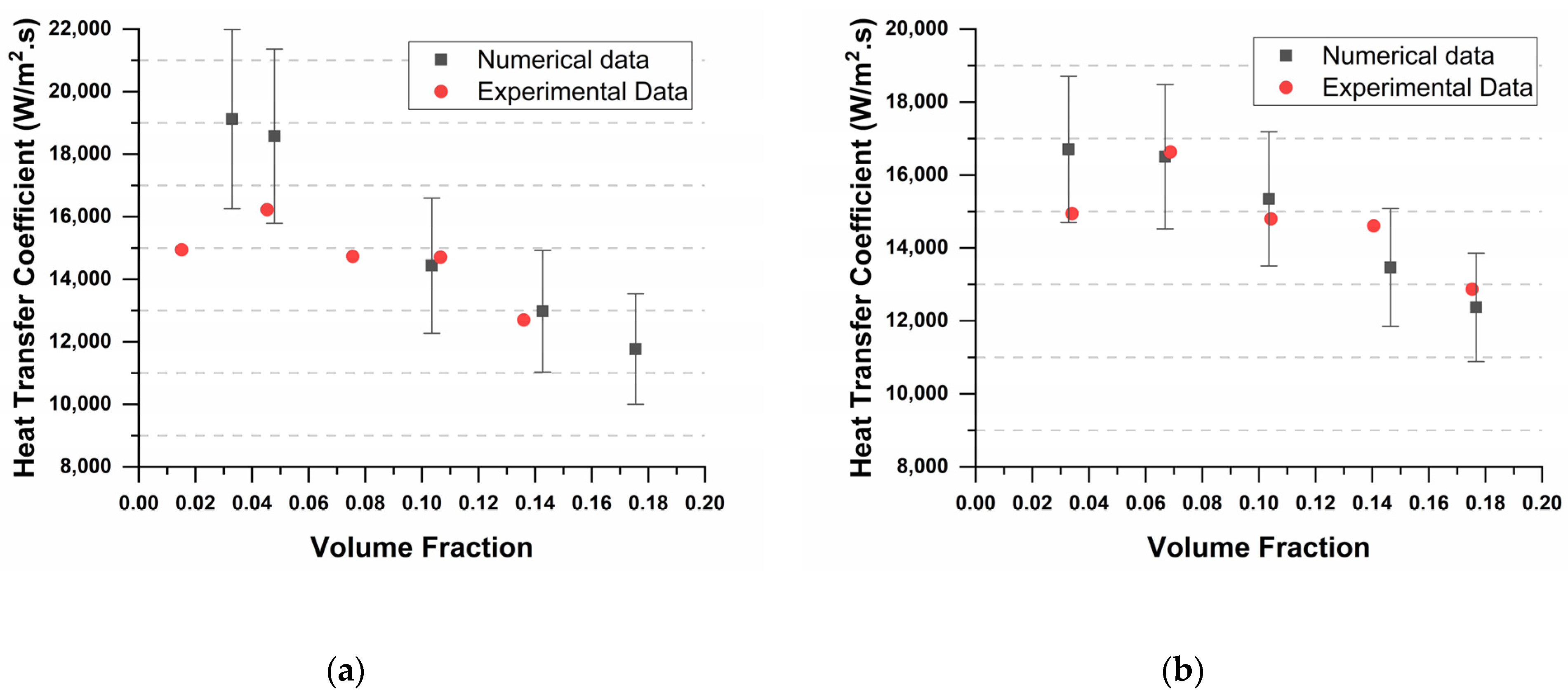
  • At a low mass flux of 11.09 kg/(m2.s), the VOF model over-predicts HTC in the NB regime and predicts linear variation of HTC. This could be attributed to the Lee phase change model, which depends on the linear deviation of bulk temperature from saturation temperature.
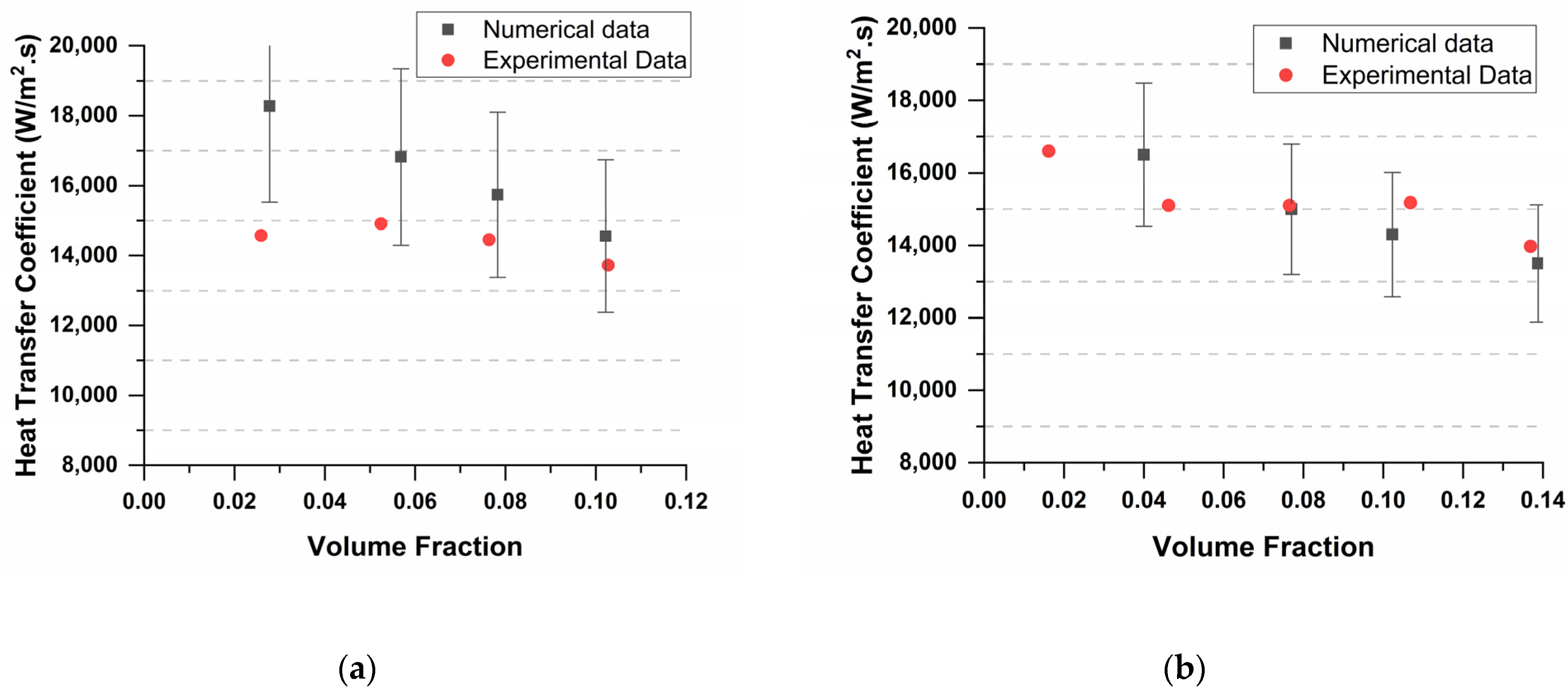
  • At moderate mass fluxes, the model shows a decrease in over-prediction, and a slight under-prediction of HTC is seen in convection boiling regimes.
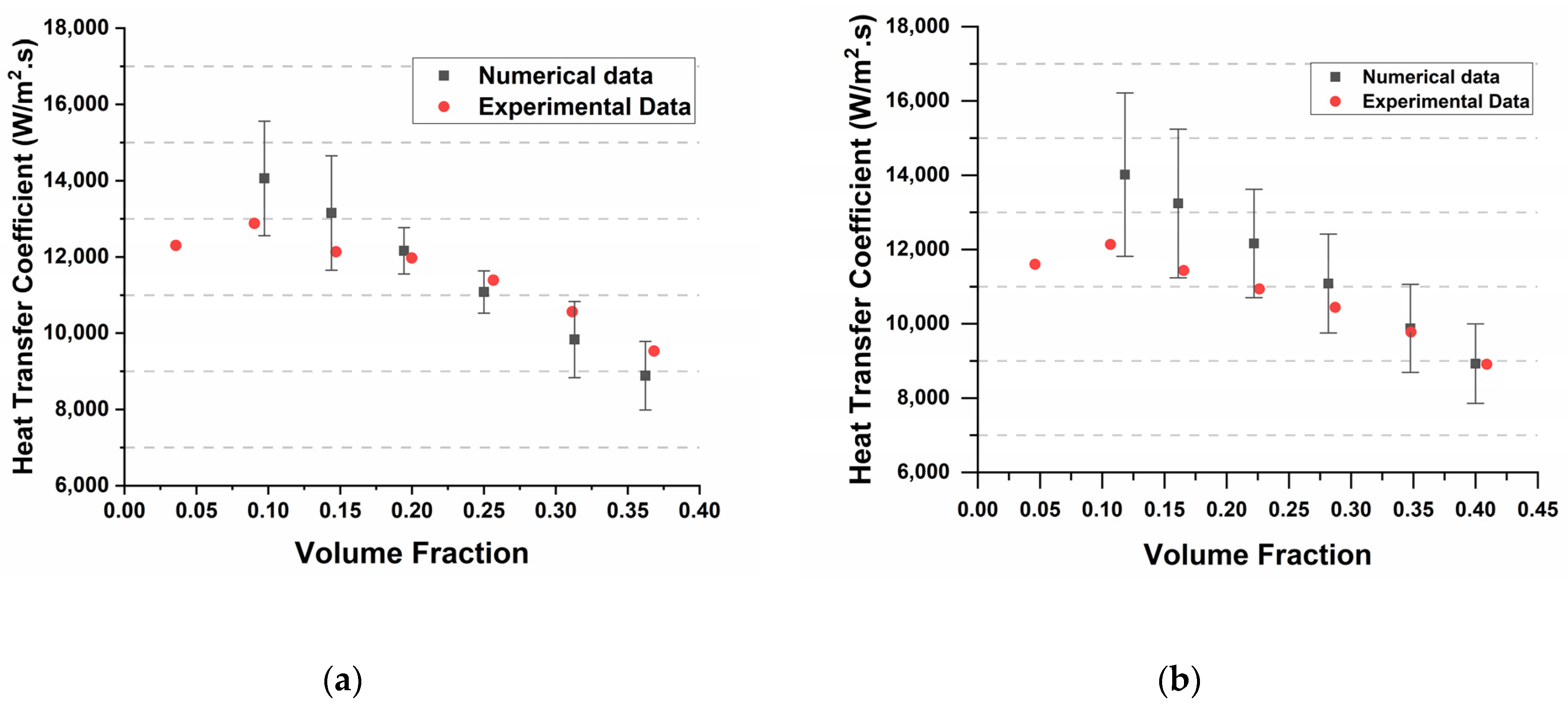
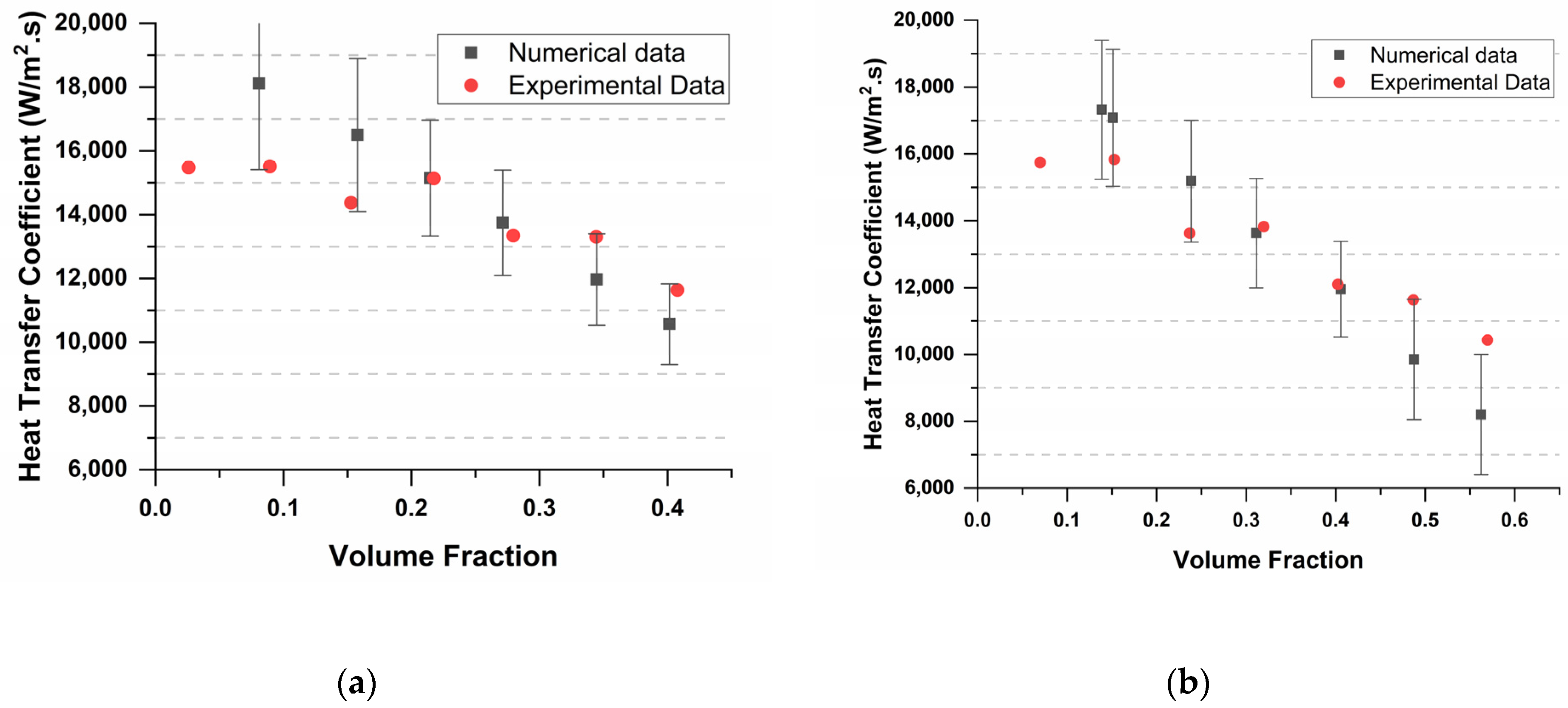
  • The model best predicts HTC at high mass fluxes, wherein numerical results exactly follow experimental results. The maximum error also comes down to +7%.
The results show that the VOF model, coupled with the Lee phase change model, can predict the heat transfer performance of a parallel mini-channel. Thus, the VOF model can be applied to designing two-phase heat transfer systems such as steam generators with reasonable accuracy. Furthermore, this model could also be used to avoid failures in these systems when the HTC drops below the minimum values as dictated by the overall system design.

Author Contributions

Conceptualization, K.W. and M.I.S.; methodology, M.U.K.M.; software, M.U.K.M.; validation, M.U.K.M. and A.E.; formal analysis, M.U.K.M.; investigation, M.U.K.M. and A.E.; resources, M.U.K.M. and M.I.S.; data curation, M.U.K.M.; writing—original draft preparation, M.U.K.M.; writing—review and editing, M.U.K.M., A.H.M. and A.E.; visualization, K.W., M.U.K.M., Z.H. and A.H.M.; supervision, K.W., A.E. and Z.H.; project administration, M.I.S., Z.H. All authors have read and agreed to the published version of the manuscript.

Funding

This research was supported by the Transdisciplinary Research Grant Scheme TRGS/1/2020/UKM/02/1/1 and the UKM internal grant GUP-2018-012.

Informed Consent Statement

Informed consent was obtained from all subjects involved in the study.

Data Availability Statement

The raw data supporting the conclusions of this article will be made available by the authors on request.

Conflicts of Interest

The authors declare no conflict of interest.

References

  1. Silvi, L.D.; Chandraker, D.K.; Ghosh, S.; Das, A.K. Understanding Dry-out Mechanism in Rod Bundles of Boiling Water Reactor. Int. J. Heat Mass Transf. 2021, 177, 121534. [Google Scholar] [CrossRef]
  2. Konishi, C.; Mudawar, I. Review of Flow Boiling and Critical Heat Flux in Microgravity. Int. J. Heat Mass Transf. 2015, 80, 469–493. [Google Scholar] [CrossRef]
  3. Wang, J.X.; Guo, W.; Xiong, K.; Wang, S.N. Review of Aerospace-Oriented Spray Cooling Technology. Prog. Aerosp. Sci. 2020, 116, 100635. [Google Scholar] [CrossRef]
  4. Leong, K.C.; Ho, J.Y.; Wong, K.K. A Critical Review of Pool and Flow Boiling Heat Transfer of Dielectric Fluids on Enhanced Surfaces. Appl. Therm. Eng. 2017, 112, 999–1019. [Google Scholar] [CrossRef]
  5. Liu, X.; Su, G.; Yao, Z.; Yan, Z.; Yu, Y. Numerical Study of Flow Boiling of ADN-Based Liquid Propellant in a Capillary. Materials 2023, 16, 1858. [Google Scholar] [CrossRef] [PubMed]
  6. Wang, J.; Wang, B.; Xie, J.; Lei, K.; Yu, B.; Sun, Y. Numerical Simulation Research of Bubble Characteristics and Bubble Departure Diameter in Subcooled Flow Boiling. Mathematics 2022, 10, 4103. [Google Scholar] [CrossRef]
  7. Hu, C.; Wang, R.; Yang, P.; Ling, W.; Zeng, M.; Qian, J.; Wang, Q. Numerical Investigation on Two-Phase Flow Heat Transfer Performance and Instability with Discrete Heat Sources in Parallel Channels. Energies 2021, 14, 4408. [Google Scholar] [CrossRef]
  8. Fsadni, A.M.; Whitty, J.P.M. A Review on the Two-Phase Heat Transfer Characteristics in Helically Coiled Tube Heat Exchangers. Int. J. Heat Mass Transf. 2016, 95, 551–565. [Google Scholar] [CrossRef]
  9. Owhadi, A.; Bell, K.J.; Crain, B. Forced Convection Boiling inside Helically-Coiled Tubes. Int. J. Heat Mass Transf. 1968, 11, 1779–1793. [Google Scholar] [CrossRef]
  10. Chen, J.C. Correlation for Boiling Heat Transfer to Saturated Fluids in Convective Flow. Ind. Eng. Chem. Process Des. Dev. 1966, 5, 322–329. [Google Scholar] [CrossRef]
  11. Steiner, D.; Taborek, J. Flow Boiling Heat Transfer in Vertical Tubes Correlated by an Asymptotic Model. Heat Transf. Eng. 1992, 13, 43–69. [Google Scholar] [CrossRef]
  12. Niu, X.; Yuan, H.; Zhao, L. Experimental Study on Critical Heat Flux during Flow Boiling of R134a in a Vertical Helically Coiled Tube. Proc. Inst. Mech. Eng. Part C J. Mech. Eng. Sci. 2020, 234, 3094–3101. [Google Scholar] [CrossRef]
  13. Tanaka, K. NII-Electronic Library Service. Chem. Pharm. Bull. 1977, 57, 364–370. [Google Scholar]
  14. Guo, L., Chen. Forced Convection Boiling Heat Transfer and Dryout Characteristics in Helical Coiled Tubes with Various Axial Angles. In Proceedings of the 11th Conference IHTC, Kyongju, Republic of Korea, 23–28 August 1988; Volume 2, pp. 261–266. [Google Scholar]
  15. Zhao, L.; Guo, L.; Bai, B.; Hou, Y.; Zhang, X. Convective Boiling Heat Transfer and Two-Phase Flow Characteristics inside a Small Horizontal Helically Coiled Tubing Once-through Steam Generator. Int. J. Heat Mass Transf. 2003, 46, 4779–4788. [Google Scholar] [CrossRef]
  16. Yi, J.; Liu, Z.-H.; Wang, J. Heat Transfer Characteristics of the Evaporator Section Using Helical Coiled Pipes in a Looped Heat Pipe. Appl. Therm. Eng. 2003, 23, 89–99. [Google Scholar] [CrossRef]
  17. Chen, S.W.; Hsieh, J.C.; Chou, C.T.; Lin, H.H.; Shen, S.C.; Tsai, M.J. Experimental Investigation and Visualization on Capillary and Boiling Limits of Microgrooves Made by Different Processes. Sens. Actuat. 2007, A139, 78–87. [Google Scholar] [CrossRef]
  18. Hendricks, T.J.; Krishnan, S.; Choi, C.; Chang, C.H.; Paul, B. Enhancement of Pool Boiling Heat Transfer Using Nanostructured Surfaces on Aluminum and Copper. ASME Int. Mech. Eng. Congr. Expo. Proc. 2010, 12, 1025–1033. [Google Scholar] [CrossRef]
  19. Kim, S.; Kim, H.D.; Kim, H.; Ahn, H.S.; Jo, H.; Kim, J.; Kim, M.H. Effects of Nano-Fluid and Surfaces with Nano Structure on the Increase of CHF. Exp. Therm. Fuild Sci. 2010, 34, 487–495. [Google Scholar] [CrossRef]
  20. Ahn, H.S.; Park, G.; Kim, J.M.; Kim, J.; Kim, M.H. The Effect of Water Absorption on Critical Heat Flux Enhancement during Pool Boiling. Exp. Therm. Fluid Sci. 2012, 42, 187–195. [Google Scholar] [CrossRef]
  21. Etminan, A.; Muzychka, Y.S.; Pope, K. A Review on the Hydrodynamics of Taylor Flow in Microchannels: Experimental and Computational Studies. Processes 2021, 9, 870. [Google Scholar] [CrossRef]
  22. Mukherjee, A.; Kandlikar, S.G. Numerical Simulation of Growth of a Vapor Bubble during Flow Boiling of Water in a Microchannel. Microfluid. Nanofluidics 2005, 1, 137–145. [Google Scholar] [CrossRef]
  23. Mukherjee, A.; Kandlikar, S.G. The Effect of Inlet Constriction on Bubble Growth during Flow Boiling in Microchannels. Int. J. Heat Mass Transf. 2009, 52, 5204–5212. [Google Scholar] [CrossRef]
  24. Lee, W.; Son, G. Bubble Dynamics and Heat Transfer during Nucleate Boiling in a Microchannel. Numer. Heat Transf. Part Appl. 2008, 53, 1074–1090. [Google Scholar] [CrossRef]
  25. Ewe, W.E.; Fudholi, A.; Sopian, K.; Solomin, E.; Yazdi, M.H.; Asim, N.; Fatima, N.; Pikra, G.; Sudibyo, H.; Fatriasari, W.; et al. Jet Impingement Cooling Applications in Solar Energy Technologies: Systematic Literature Review. Therm. Sci. Eng. Prog. 2022, 34, 101445. [Google Scholar] [CrossRef]
  26. Etminan, A.; Harun, Z. Forced Convective Heat Transfer Analysis for Two-Dimensional Slot Jet of Water-CuO Nanofluid. J. Kejuruter. 2021, 33, 229–238. [Google Scholar] [CrossRef] [PubMed]
  27. Hasan, H.; Alquziweeni, Z.; Sopian, K. Heat Transfer Enhancement Using Nanofluids for Cooling a Central Processing Unit (CPU) System. J. Adv. Res. Fluid Mech. Therm. Sci. 2018, 51, 145–157. [Google Scholar]
  28. Faris Abdullah, M.; Zulkifli, R.; Harun, Z.; Abdullah, S.; Wan Ghopa, W.A.; Soheil Najm, A.; Humam Sulaiman, N. Impact of the TiO2 Nanosolution Concentration on Heat Transfer Enhancement of the Twin Impingement Jet of a Heated Aluminum Plate. Micromachines 2019, 10, 176. [Google Scholar] [CrossRef]
  29. Zu, Y.Q.; Yan, Y.Y.; Gedupudi, S.; Karayiannis, T.G.; Kenning, D.B.R. Confined Bubble Growth during Flow Boiling in a Mini-/Micro-Channel of Rectangular Cross-Section Part II: Approximate 3-D Numerical Simulation. Int. J. Therm. Sci. 2011, 50, 267–273. [Google Scholar] [CrossRef]
  30. Garoosi, F.; Hooman, K. Numerical Simulation of Multiphase Flows Using an Enhanced Volume-of-Fluid (VOF) Method. Int. J. Mech. Sci. 2022, 215, 106956. [Google Scholar] [CrossRef]
  31. Zhuan, R.; Wang, W. Simulation on Nucleate Boiling in Micro-Channel. Int. J. Heat Mass Transf. 2010, 53, 502–512. [Google Scholar] [CrossRef]
  32. Mulbah, C.; Kang, C.; Mao, N.; Zhang, W.; Shaikh, A.R.; Teng, S. A Review of VOF Methods for Simulating Bubble Dynamics. Prog. Nucl. Energy 2022, 154, 104478. [Google Scholar] [CrossRef]
  33. Zhao, S.; Zhang, J.; Ni, M.-J. Boiling and Evaporation Model for Liquid-Gas Flows: A Sharp and Conservative Method Based on the Geometrical VOF Approach. J. Comput. Phys. 2022, 452, 110908. [Google Scholar] [CrossRef]
  34. Zhang, J.; An, J.; Lei, L.; Wang, X.; Xin, G.; Wu, Z. Numerical Investigation of Heat Transfer and Pressure Drop Characteristics of Flow Boiling in Manifold Microchannels with a Simple Multiphase Model. Int. J. Heat Mass Transf. 2023, 211, 124197. [Google Scholar] [CrossRef]
  35. Vaishnavi, G.N.V.S.; Ramarajan, J.; Jayavel, S. Numerical Studies of Bubble Formation Dynamics in Gas-Liquid Interaction Using Volume of Fluid (VOF) Method. Therm. Sci. Eng. Prog. 2023, 39, 101718. [Google Scholar] [CrossRef]
  36. Lin, C.-W.; Lin, Y.-C.; Kumar, R.; Lin, M.-C.; Hsu, H.-Y. A Numerical Study of Microtube Geometry Effect on Flow Boiling Using the Volume of Fluid Method. Int. J. Heat Mass Transf. 2022, 199, 123477. [Google Scholar] [CrossRef]
  37. Bureš, L.; Sato, Y. Direct Numerical Simulation of Evaporation and Condensation with the Geometric VOF Method and a Sharp-Interface Phase-Change Model. Int. J. Heat Mass Transf. 2021, 173, 121233. [Google Scholar] [CrossRef]
  38. Shang, X.; Zhang, X.; Nguyen, T.-B.; Tran, T. Direct Numerical Simulation of Evaporating Droplets Based on a Sharp-Interface Algebraic VOF Approach. Int. J. Heat Mass Transf. 2022, 184, 122282. [Google Scholar] [CrossRef]
  39. Etminan, A.; Muzychka, Y.S.; Pope, K. CFD Modelling for Gas-Liquid and Liquid-Liquid Taylor Flows in the Entrance Region of Microchannels. In Proceedings of the Fluids Engineering Division Summer Meeting, Virtual Conference, Online, 10–12 August 2021. [Google Scholar]
  40. Tang, T.L.; Salleh, H.; Sadiq, M.I.; Mohd Sabri, M.A.; Ahmad, M.I.M.; Ghopa, W.A.W. Experimental and Numerical Investigation of Flow Structure and Heat Transfer Behavior of Multiple Jet Impingement Using MgO-Water Nanofluids. Materials 2023, 16, 3942. [Google Scholar] [CrossRef]
  41. Sadiq, M.I.; Ghopa, W.A.W.; Nuawi, M.Z.; Rasani, M.R.; Mohd Sabri, M.A. Experimental and Numerical Investigation of Static and Dynamic Characteristics of Bio-Oils and SAE40 in Fluid Film Journal Bearing. Materials 2022, 15, 3595. [Google Scholar] [CrossRef] [PubMed]
  42. Zhuan, R.; Wang, W. Simulation of Subcooled Flow Boiling in a Micro-Channel. Int. J. Refrig. 2011, 34, 781–795. [Google Scholar] [CrossRef]
  43. Warrier, G.R.; Basu, N.; Dhir, V.K. Interfacial Heat Transfer during Subcooled Flow Boiling. Int. J. Heat Mass Transf. 2002, 45, 3947–3959. [Google Scholar] [CrossRef]
  44. Pan, L.; Tan, Z.; Chen, D.; Xue, L. Numerical Investigation of Vapor Bubble Condensation Characteristics of Subcooled Flow Boiling in Vertical Rectangular Channel. Nucl. Eng. Des. 2012, 248, 126–136. [Google Scholar] [CrossRef]
  45. Wu, H.L.; Peng, X.F.; Ye, P.; Eric Gong, Y. Simulation of Refrigerant Flow Boiling in Serpentine Tubes. Int. J. Heat Mass Transf. 2007, 50, 1186–1195. [Google Scholar] [CrossRef]
  46. Fang, C.; David, M.; Rogacs, A.; Goodson, K. Volume of Fluid Simulation of Boiling Two-Phase Flow in a Vapor Venting Microchannel. Front. Heat Mass Transf. 2010, 1, 013002. [Google Scholar] [CrossRef]
  47. Chen, Y.J.; Ling, K.; Jin, S.Q.; Lu, W.; Yu, B.; Sun, D.; Zhang, W.; Tao, W.Q. Numerical Investigation of Critical Heat Flux during Subcooled Flow Boiling in a Vertical Rectangular Mini-Channel. Appl. Therm. Eng. 2023, 221, 119862. [Google Scholar] [CrossRef]
  48. Rabhi, A.; Aslanidou, I.; Kyprianidis, K.; Bel Fdhila, R. Onset of Nucleate Boiling Model for Rectangular Upward Narrow Channel: CFD Based Approach. Int. J. Heat Mass Transf. 2021, 165, 120715. [Google Scholar] [CrossRef]
  49. Jain, S.; Jayaramu, P.; Gedupudi, S. Modeling of Pressure Drop and Heat Transfer for Flow Boiling in a Mini/Micro-Channel of Rectangular Cross-Section. Int. J. Heat Mass Transf. 2019, 140, 1029–1054. [Google Scholar] [CrossRef]
  50. Chen, Y.; Jin, S.; Yu, B.; Ling, K.; Sun, D.; Zhang, W.; Jiao, K.; Tao, W. Modeling and Study of Microlayer Effects on Flow Boiling in a Mini-Channel. Int. J. Heat Mass Transf. 2023, 208, 124039. [Google Scholar] [CrossRef]
  51. Wang, Z.; Qi, X.; Zhuang, Y.; Wang, Q.; Sun, X. Effect of Flow Field and Electric Field Coupling on Oil-Water Emulsion Separation. Desalination Water Treat. 2023, 283, 79–96. [Google Scholar] [CrossRef]
  52. Qi, X.; Zhang, H.; Sun, X.; Wang, Z. Numerical Investigation on Flow-Field Characteristics towards Removal of Free-Water by A Separator with Coalescing Plates. J. Adv. Appl. Comput. Math. 2023, 10, 1–17. [Google Scholar] [CrossRef]
  53. Bard, A.; Qiu, Y.; Kharangate, C.R.; French, R. Consolidated Modeling and Prediction of Heat Transfer Coefficients for Saturated Flow Boiling in Mini/Micro-Channels Using Machine Learning Methods. Appl. Therm. Eng. 2022, 210, 118305. [Google Scholar] [CrossRef]
  54. Liu, D.Y.; Weng, X.; Xu, X.G. Experimental Study on the Heat Transfer Coefficient of Water Flow Boiling in Mini/Microchannels. Exp. Therm. Fluid Sci. 2011, 35, 1392–1397. [Google Scholar] [CrossRef]
  55. Shin, C.W.; No, H.C. Experimental Study for Pressure Drop and Flow Instability of Two-Phase Flow in the PCHE-Type Steam Generator for SMRs. Nucl. Eng. Des. 2017, 318, 109–118. [Google Scholar] [CrossRef]
  56. Ahmad, T.; Plee, S.L.; Myers, J.P. ANSYS Fluent Theory Guide; Ansys Inc.: Canonsburg, PA, USA, 2011. [Google Scholar]
  57. Lee, W.H. A Pressure Iteration Scheme for Two-Phase Flow Modeling. Multiph. Transp. Fundam. React. Saf. Appl. 1980, 1, 162–198. [Google Scholar] [CrossRef]
  58. Todreas, N.E.; Kazimi, M.S. Nuclear Systems: Thermal Hydraulic Fundamentals, 2nd ed.; CRC Press: Boca Raton, FL, USA, 2012; Volume 1, ISBN 978-1-4398-0888-7. [Google Scholar]
Figure 1. Boundary conditions for the computational domain.
Applsci 14 00759 g001
Figure 2. Research methodology.
Applsci 14 00759 g002
Figure 3. Mesh independence study.
Applsci 14 00759 g003
Figure 4. Distributions of the heat transfer coefficients versus volume fraction at G = 11.09 kg/(m2.s) (a) Q = 11.75 W/cm2 (b) Q = 14.81 W/cm2 (Numerical data versus Experimental data Liu et al. [54]).
Applsci 14 00759 g004
Figure 5. Variation of the heat transfer coefficients versus volume fraction at G = 11.09 kg/(m2.s) (a) Q = 17.88 W/cm2 (b) Q = 19.57 W/cm2 (Numerical data versus Experimental data Liu et al. [54]).
Applsci 14 00759 g005
Figure 6. Distribution of the heat transfer coefficients against volume fraction at G = 22.18 kg/(m2.s) (a) Q = 16.90 W/cm2 (b) Q = 20.65 W/cm2 (Numerical data versus Experimental data Liu et al. [54]).
Applsci 14 00759 g006
Figure 7. Distribution of the heat transfer coefficients versus volume fraction at G = 22.18 kg/(m2.s) (a) Q = 41.35 W/cm2 (b) Q = 53.93 W/cm2 (Numerical data versus Experimental data Liu et al. [54]).
Applsci 14 00759 g007
Figure 8. Distribution of the heat transfer coefficients versus volume fraction at G = 33.27 kg/(m2.s) (a) Q = 24.85 W/cm2 (b) Q = 29.54 W/cm2 (Numerical data versus Experimental data Liu et al. [54]).
Applsci 14 00759 g008
Figure 9. Distribution of the heat transfer coefficients versus volume fraction at G = 33.27 kg/(m2.s) and Q = 36.47 W/cm2 (Numerical data versus Experimental data Liu et al. [54]).
Applsci 14 00759 g009
Figure 10. Distribution of the heat transfer coefficients versus volume fraction at G = 44.36 kg/(m2.s) (a) Q = 41.42 W/cm2 (b) Q = 45.86 W/cm2 (Numerical data versus Experimental data Liu et al. [54]).
Applsci 14 00759 g010
Figure 11. Distribution of the heat transfer coefficients versus volume fraction at G = 44.36 kg/(m2.s) and Q = 48.65 W/cm2 (Numerical data versus Experimental data Liu et al. [54]).
Applsci 14 00759 g011
Disclaimer/Publisher’s Note: The statements, opinions and data contained in all publications are solely those of the individual author(s) and contributor(s) and not of MDPI and/or the editor(s). MDPI and/or the editor(s) disclaim responsibility for any injury to people or property resulting from any ideas, methods, instructions or products referred to in the content.

