

Designing and Manufacturing an Affordable and Easy to Use Visual Bio Feedback Device to Fix Forward Head Posture: A Pilot Study Involving Female Students


Abstract
1. Introduction
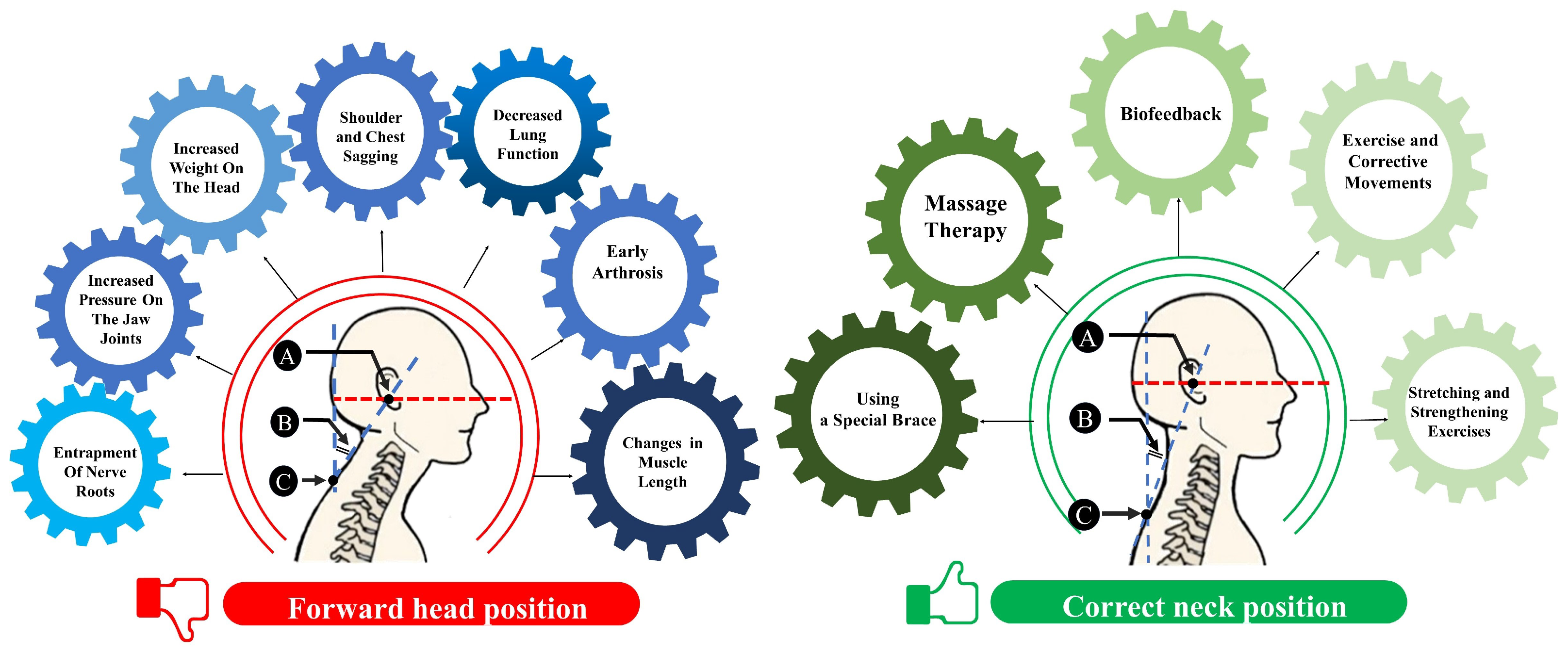
1.1. FHP Reasons and Causes
1.2. Treatment Modalities and Strategies
2. Related Works
- Apply biofeedback (visual feedback) techniques in an innovative manner to address anatomical issues related to the cervical vertebrae.
- Develop a pioneering system that utilizes accelerometer sensors to comprehensively characterize neck angular behavior.
- Seamlessly integrate the developed system with the MATLAB program’s graphical interface.
- Provide individuals with a visual representation of their neck behavior to enhance awareness.
- Enable individuals to observe and gain awareness of maladaptive neck positioning.
- Foster a pathway for self-correction of neck angle anomalies.
- Empower individuals to actively participate in improving their health and wellbeing through visual feedback methodologies.
3. Materials and Method
3.1. Participants
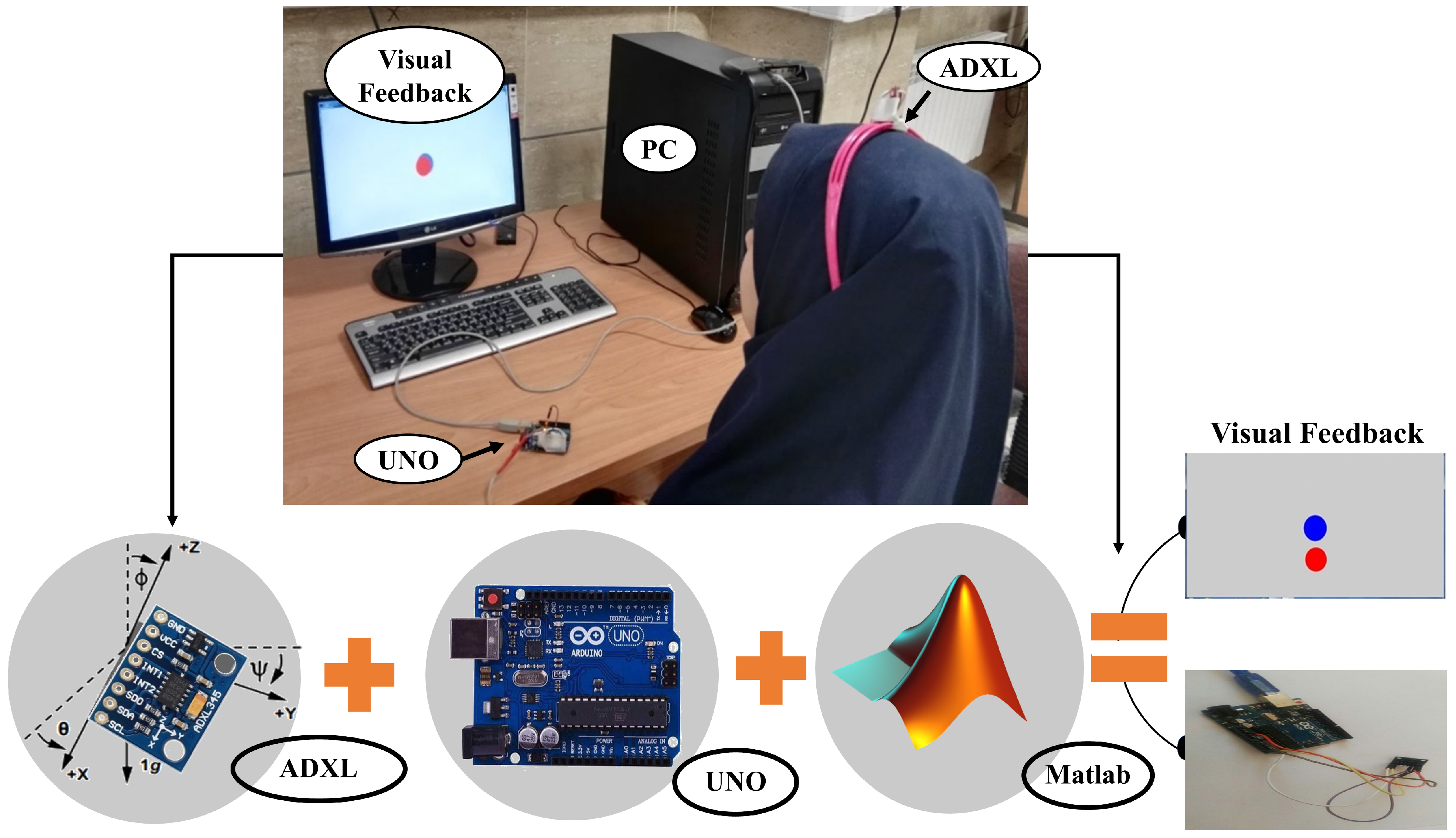
3.2. Hardware
3.3. Software
- Data Acquisition: data from the Arduino are read from the file using the ‘fscanf’ command. The program defines parameters related to the accelerometer sensor, including ‘MaxValue’, ‘Resolution’, ‘Fs’ (sampling frequency), and ‘MaxAcc_g’.
- Data Storage Loop: a loop is established to collect accelerometer sensor values, specifically, the acceleration values in the Earth’s gravity direction (x, y, and z axes); these values are stored in the ‘xyz’ variable over a period of 120 s.
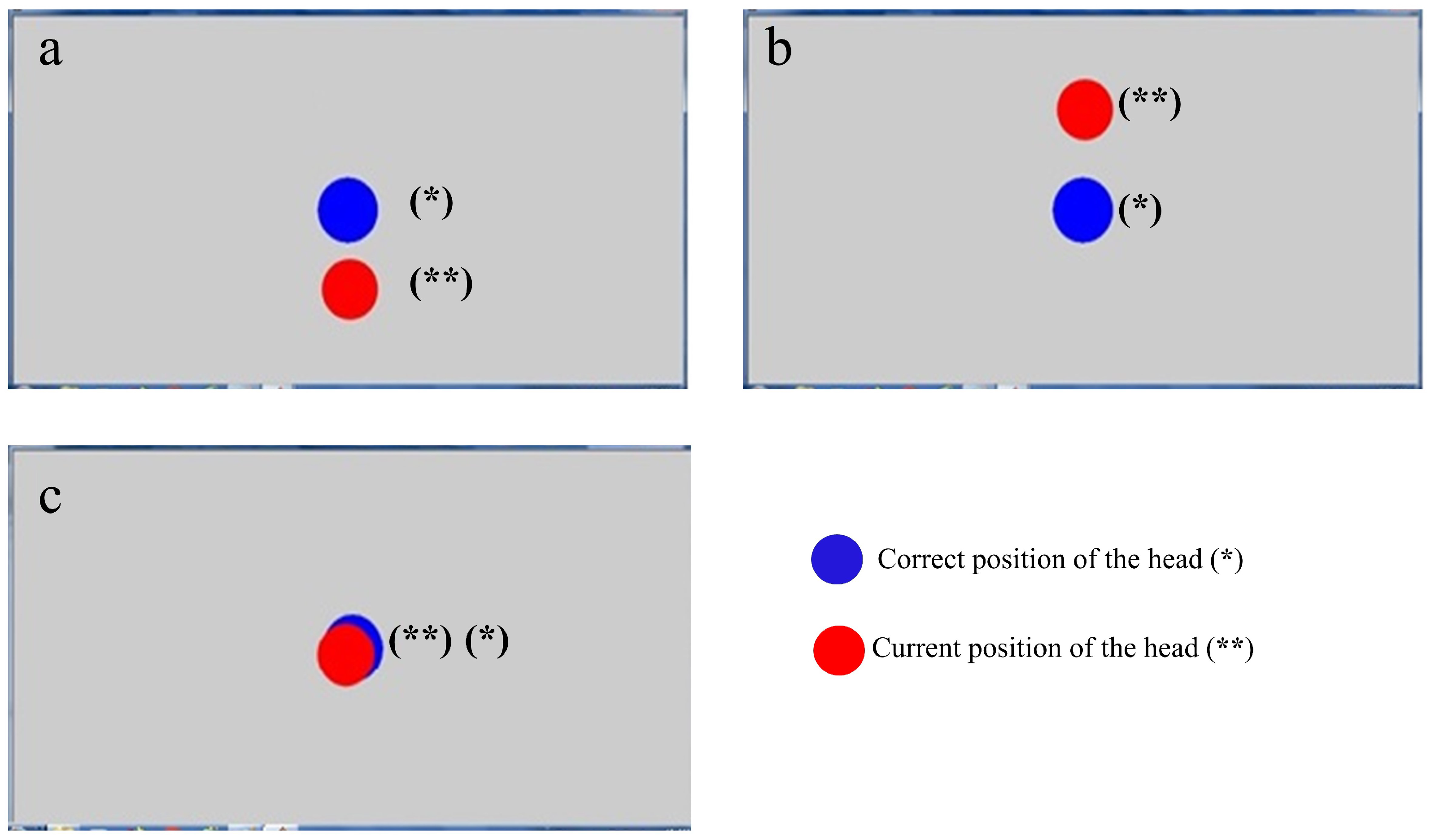
- Visualization Step: the program employs the ‘plot’ command to draw a blue circle at the center of the monitor screen to serve as a reference point, and maintains it on the screen using the ‘hold on’ command.
- Angle Calculation: the accelerometer sensor supplies data regarding the Earth’s gravitational acceleration in the x, y, and z directions. Using these values, the program computes the head’s angle for both forward and backward bending as well as left and right bending directions using Equations (2) and (3), respectively.
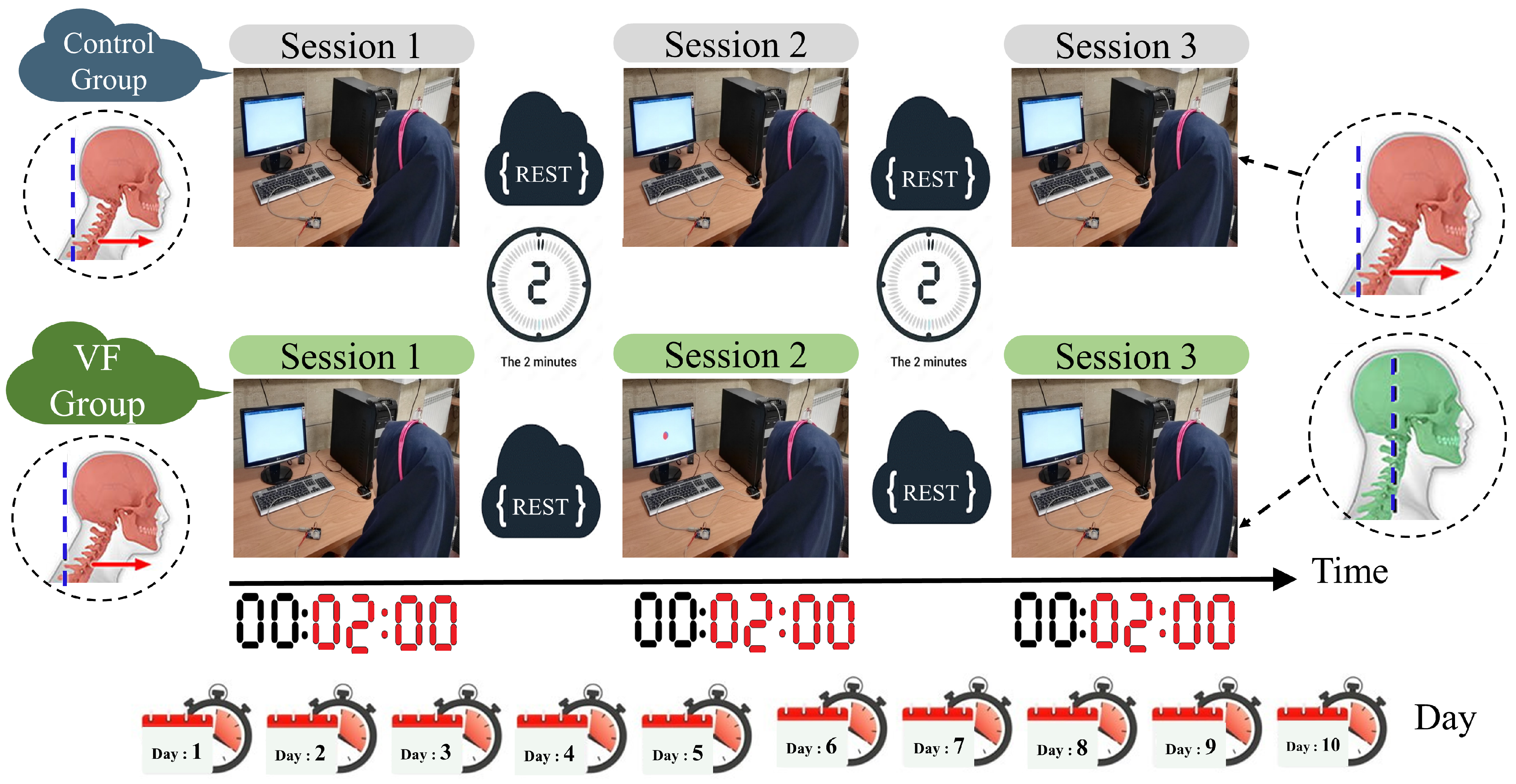
3.4. Data Collection and Protocol
3.5. Metrics
DFA Number
3.6. Statistical Analysis and Results
4. Results
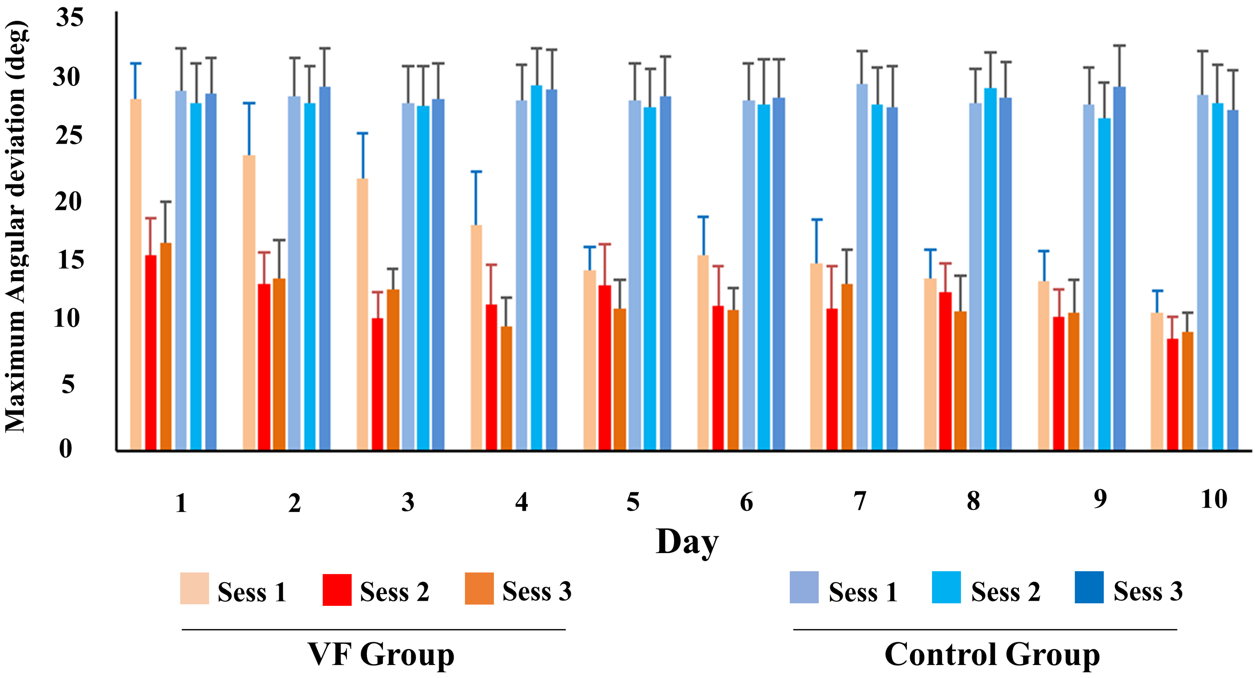
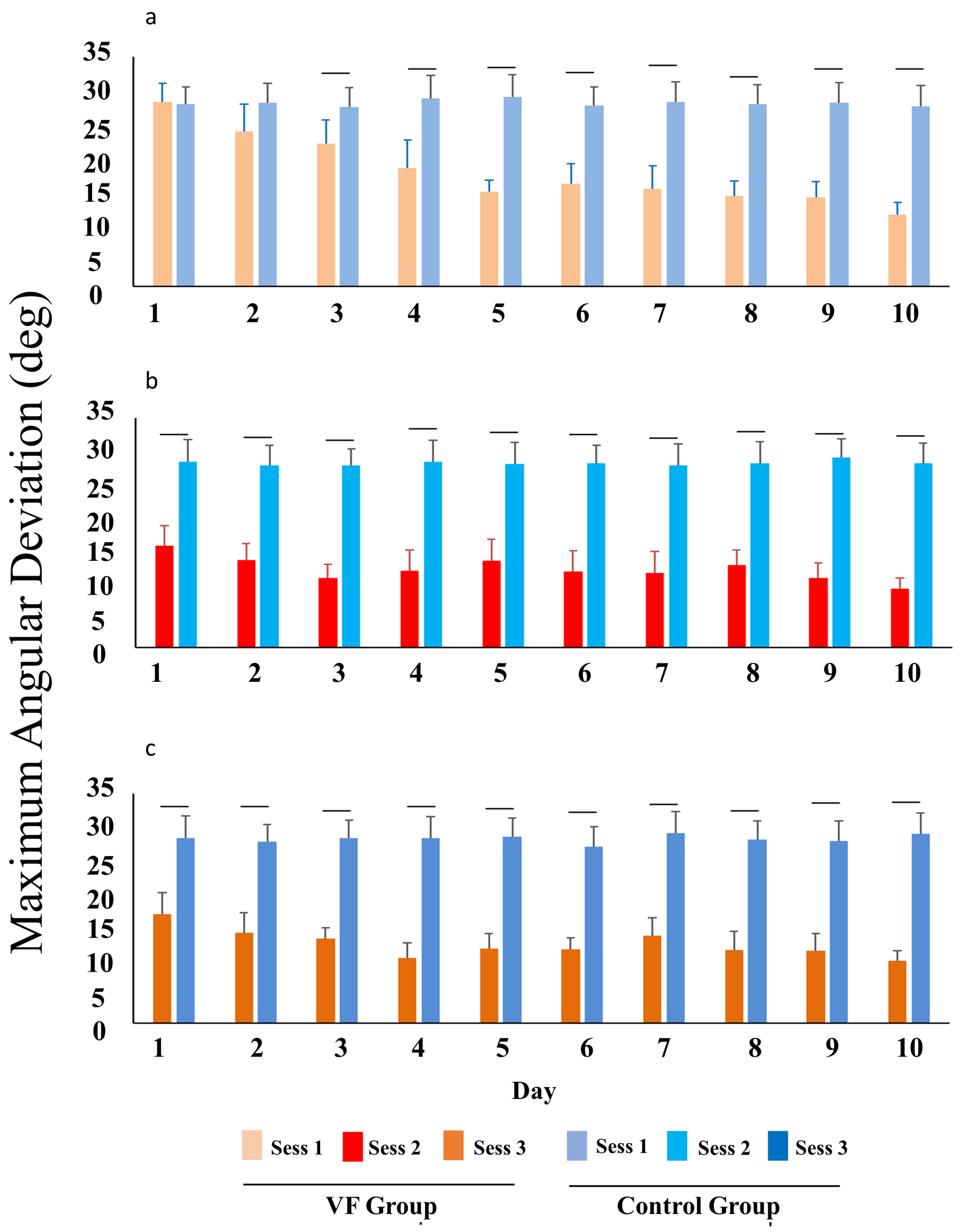
4.1. Maximum Head Angle Deviation
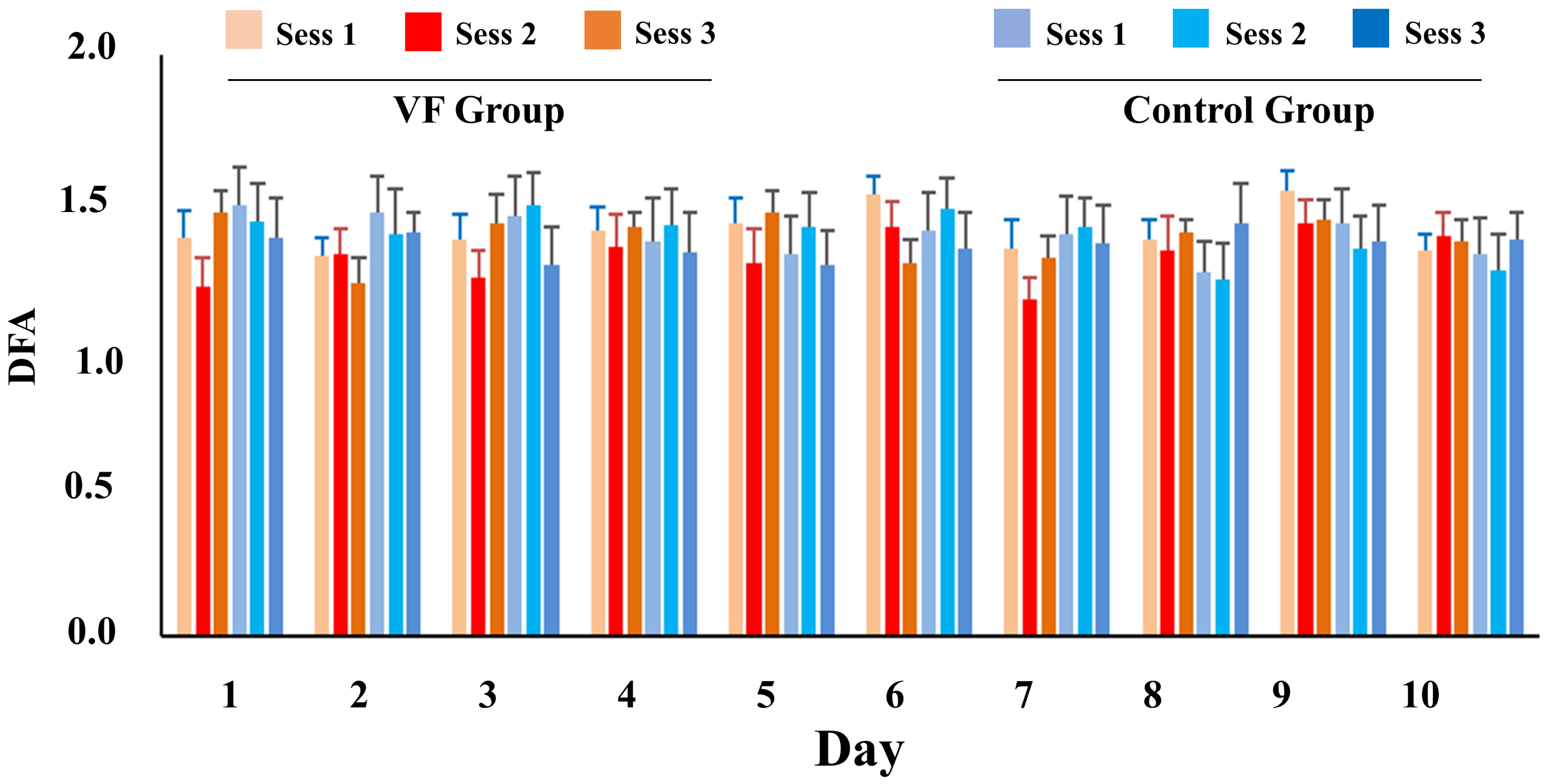
4.2. DFA Number
5. Conclusions and Suggestions
Author Contributions
Funding
Institutional Review Board Statement
Informed Consent Statement
Data Availability Statement
Acknowledgments
Conflicts of Interest
References
- Yip, C.H.T.; Chiu, T.T.W.; Poon, A.T.K. The relationship between head posture and severity and disability of patients with neck pain. Man. Ther. 2008, 13, 148–154. [Google Scholar] [CrossRef]
- Chansirinukor, W.; Wilson, D.; Grimmer, K.; Dansie, B. Effects of backpacks on students: Measurement of cervical and shoulder posture. Aust. J. Physiother. 2001, 47, 110–116. [Google Scholar] [CrossRef]
- Kang, J.H.; Park, R.Y.; Lee, S.J.; Kim, J.Y.; Yoon, S.R.; Jung, K.I. The effect of the forward head posture on postural balance in long time computer based worker. Ann. Rehabil. Med. 2012, 36, 98–104. [Google Scholar] [CrossRef]
- Kullgren, A.; Krafft, M.; Nygren, Å.; Tingvall, C. Neck injuries in frontal impacts: Influence of crash pulse characteristics on injury risk. Accid. Anal. Prev. 2000, 32, 197–205. [Google Scholar] [CrossRef]
- Daneshmandi, H.; Majalan, A.S.; Babakhani, M. The comparison of head and neck alignment in children with visual and hearing impairments and its relation with anthropometrical dimensions. Phys. Treat. 2014, 4, 69–76. [Google Scholar]
- Guevara, C.; Jadán-Guerrero, J.; Bonilla-Jurado, D.; Salvador-Ullauri, L.; Acosta-Vargas, P.; Calle-Jimenez, T.; Lara-Alvarez, P. Fuzzy Model for Back Posture Correction During the Walk. In Proceedings of the International Conference on Applied Human Factors and Ergonomics, Washington, DC, USA, 24–28 July 2019; Springer: Cham, Switzerland, 2019; pp. 299–305. [Google Scholar]
- Han, G.H.; Yi, C.H.; Kim, S.H.; Kim, S.B.; Lim, O.B. Test–retest Reliability and Concurrent Validity of a Headphone and Necklace Posture Correction System Developed for Office Workers. Phys. Ther. Korea 2023, 30, 174–183. [Google Scholar] [CrossRef]
- Mahmoud, N.F.; Hassan, K.A.; Abdelmajeed, S.F.; Moustafa, I.M.; Silva, A.G. The relationship between forward head posture and neck pain: A systematic review and meta-analysis. Curr. Rev. Musculoskelet. Med. 2019, 12, 562–577. [Google Scholar] [CrossRef]
- Fernández-de-Las-Peñas, C.; Cuadrado, M.L.; Pareja, J.A. Myofascial trigger points, neck mobility and forward head posture in unilateral migraine. Cephalalgia 2006, 26, 1061–1070. [Google Scholar] [CrossRef]
- Ruivo, R.M.; Pezarat-Correia, P.; Carita, A.I. Effects of a resistance and stretching training program on forward head and protracted shoulder posture in adolescents. J. Manip. Physiol. Ther. 2017, 40, 1–10. [Google Scholar] [CrossRef]
- Cole, A.K.; McGrath, M.L.; Harrington, S.E.; Padua, D.A.; Rucinski, T.J.; Prentice, W.E. Scapular bracing and alteration of posture and muscle activity in overhead athletes with poor posture. J. Athl. Train. 2013, 48, 12–24. [Google Scholar] [CrossRef] [PubMed]
- Avery, R.M. Massage therapy for cervical degenerative disc disease: Alleviating a pain in the neck? Int. J. Ther. Massage Bodyw. 2012, 5, 41. [Google Scholar]
- Kim, D.; Cho, M.; Park, Y.; Yang, Y. Effect of an exercise program for posture correction on musculoskeletal pain. J. Phys. Ther. Sci. 2015, 27, 1791–1794. [Google Scholar] [CrossRef] [PubMed]
- Abdollahzade, Z.; Shadmehr, A.; Malmir, K.; Ghotbi, N. Effects of 4 week postural corrective exercise on correcting forward head posture. J. Mod. Rehabil. 2017, 11, 85–92. [Google Scholar]
- Frank, D.L.; Khorshid, L.; Kiffer, J.F.; Moravec, C.S.; McKee, M.G. Biofeedback in medicine: Who, when, why and how? Ment. Health Fam. Med. 2010, 7, 85. [Google Scholar]
- Mohamed, A.A.; Jan, Y.K.; Raoof, N.A.; Kattabei, O.; Moustafa, I.; Hosny, H. Effect of biofeedback corrective exercise on reaction time and central somatosensory conduction time in patients with forward head posture and radiculopathy: A randomized controlled study. J. Chiropr. Med. 2022, 21, 39–50. [Google Scholar] [CrossRef] [PubMed]
- Peper, E.; Shaffer, F. Biofeedback history: An alternative view. Biofeedback 2018, 46, 80–85. [Google Scholar] [CrossRef]
- Afzal, M.R.; Oh, M.K.; Yoon, J. Development of a multimodal biofeedback system for balance training. In Proceedings of the IEEE International Conference of Advanced Intelligent Mechatronics (AIM), Busan, Republic of Korea, 7–11 July 2015; pp. 658–663. [Google Scholar]
- Al Osman, H.; Eid, M.; El Saddik, A. U-biofeedback: A multimedia-based reference model for ubiquitous biofeedback systems. Multimed. Tools Appl. 2014, 72, 3143–3168. [Google Scholar] [CrossRef]
- Giggins, O.M.; Persson, U.M.; Caulfield, B. Biofeedback in rehabilitation. J. Neuro Eng. Rehabil. 2013, 10, 60. [Google Scholar] [CrossRef]
- Tsai, P.S.; Chang, N.C.; Chang, W.Y.; Lee, P.H.; Wang, M.Y. Blood pressure biofeedback exerts intermediate-term effects on blood pressure and pressure reactivity in individuals with mild hypertension:a randomized controlled study. J. Altern. Complement. Med. 2007, 13, 547–554. [Google Scholar] [CrossRef] [PubMed]
- Patel, C.; Datey, K.K. Relaxation and biofeedback techniques in the management of hypertension. Angiology 1976, 27, 106–113. [Google Scholar] [CrossRef]
- Joshi, S.; Chawla, B.; Pawalia, A. Exercises in the management of forward head posture: Much needed posture care for online way of life. Physiother. Q. 2022, 30, 41–51. [Google Scholar] [CrossRef]
- Lee, K.J.; Oh, J.S.; Kim, S.G. Effect of Biomechanical Feedback Device Utilizing Tilt and Tension Sensors on Young Adults Balance Control Ability, Proprioception and Craniovertebral Angle (CVA). J. Reatt. Ther. Dev. Divers. 2023, 6, 526–534. [Google Scholar]
- Breen, P.P.; Nisar, A.; ÓLaighin, G. Evaluation of a single accelerometer based biofeedback system for real-time correction of neck posture in computer users. In Proceedings of the 2009 Annual International Conference of the IEEE Engineering in Medicine and Biology Society, Minneapolis, MN, USA, 3–6 September 2009; pp. 7269–7272. [Google Scholar]
- Lee, J.; Cho, E.; Kim, M.; Yoon, Y.; Choi, S. PreventFHP: Detection and warning system for forward head posture. In Proceedings of the 2014 IEEE Haptics Symposium (HAPTICS), Houston, TX, USA, 23–26 February 2014; pp. 295–298. [Google Scholar]
- Liao, D.Y. Design of a secure, biofeedback, head-and-neck posture correction system. In Proceedings of the 2016 IEEE First International Conference on Connected Health: Applications, Systems and Engineering Technologies (CHASE), Washington, DC, USA, 27–29 June 2016; pp. 119–124. [Google Scholar]
- Oh, H.J.; Song, G.B. Effects of neuro feedback training on the cervical movement of adults with forward head posture. J. Phys. Ther. Sci. 2016, 28, 2894–2897. [Google Scholar] [CrossRef]
- Kuo, Y.L.; Wang, P.S.; Ko, P.Y.; Huang, K.Y.; Tsai, Y.J. Immediate effects of real-time postural biofeedback on spinal posture, muscle activity, and perceived pain severity in adults with neck pain. Gait Posture 2019, 67, 187–193. [Google Scholar] [CrossRef] [PubMed]
- Andani, M.E.; Salehi, Z. An affordable and easy-to-use tool to diagnose knee arthritis using knee sound. Biomed. Signal Process. Control 2024, 88, 105685. [Google Scholar] [CrossRef]
- Alcan, V.; Zinnuroğlu, M. Current developments in surface electromyography. Turk. J. Med. Sci. 2023, 53, 1019–1031. [Google Scholar] [CrossRef]
- Thurzo, A.; Strunga, M.; Havlínová, R.; Reháková, K.; Urban, R.; Surovková, J.; Kurilová, V. Smartphone-Based Facial Scanning A Viable Tool Facially Driven Orthodontics? Sensors 2022, 12, 7752. [Google Scholar] [CrossRef] [PubMed]
- Ko, M.J.; Koo, M.S.; Jung, E.J.; Jeong, W.J.; Oh, J.S. Effect of Pelvic Floor Muscle Training Using Pressure Biofeedback on Pelvic Floor Muscle Contraction and Trunk Muscle Activity in Sitting in Healthy Women. Healthcare 2022, 10, 570. [Google Scholar] [CrossRef] [PubMed]
- Cesari, P.; Cristani, M.; Demrozi, F.; Pascucci, F.; Picotti, P.M.; Pravadelli, G.; Zenti, L. Towards Posture and Gait Evaluation through Wearable-Based Biofeedback Technologies. Electronics 2023, 12, 644. [Google Scholar] [CrossRef]
- Hribernik, M.; Umek, A.; Tomažič, S.; Kos, A. Review of real-time biomechanical feedback systems in sport and rehabilitation. Sensors 2022, 22, 3006. [Google Scholar] [CrossRef]
- Kibushi, B.; Okada, J. Auditory sEMG biofeedback for reducing muscle co-contraction during pedaling. Physiol. Rep. 2022, 10, e15288. [Google Scholar] [CrossRef]
- Toledo-Peral, C.L.; Vega-Martínez, G.; Mercado-Gutiérrez, J.A.; Rodríguez-Reyes, G.; Vera-Hernández, A.; Leija-Salas, L.; Gutiérrez-Martínez, J. Virtual/Augmented reality for rehabilitation applications using electromyography as control/biofeedback: Systematic literature review. Electronics 2022, 11, 2271. [Google Scholar] [CrossRef]
- Baer, J.L.; Vasavada, A.; Cohen, R.G. Posture biofeedback increases cognitive load. Psychol. Res. 2022, 86, 1892–1903. [Google Scholar] [CrossRef]
- Moshayedi, A.J.; Hosseinzadeh, M.; Joshi, B.P.; Emadi Andani, M. Recognition System for Ergonomic Mattress and Pillow: Design and Fabrication. IETE J. Res. 2023, 1–19. [Google Scholar] [CrossRef]
- Moshayedi, A.J.; Uddin, N.M.I.; Khan, A.S.; Zhu, J.; Emadi Andani, M. Designing and Developing a Vision-Based System to Investigate the Emotional Effects of News on Short Sleep at Noon: An Experimental Case Study. Sensors 2023, 23, 8422. [Google Scholar] [CrossRef]
- Faul, F.; Erdfelder, E.; Lang, A.G.; Buchner, A. G* Power 3: A flexible statistical power analysis program for the social, behavioral, and biomedical sciences. Behav. Res. Methods 2007, 39, 175–191. [Google Scholar] [CrossRef] [PubMed]
- Cohen, J. Statistical Power Analysis for the Behavioral Sciences, 2nd ed.; Lawrence Erlbaum Associates: Hillsdale, NJ, USA, 1988. [Google Scholar]
- Emadi Andani, M.; Villa-Sánchez, B.; Raneri, F.; Dametto, S.; Tinazzi, M.; Fiorio, M. Cathodal cerebellar tDCS combined with visual feedback improves balance control. Cerebellum 2020, 19, 812–823. [Google Scholar] [CrossRef] [PubMed]
- Moshayedi, A.J.; Sambo, S.K.; Kolahdooz, A. Design and development of cost-effective Exergames for activity incrementation. In Proceedings of the 2022 2nd International Conference on Consumer Electronics and Computer Engineering (ICCECE), Guangzhou, China, 14–16 January 2022. [Google Scholar] [CrossRef]
- Cueva, J.H.; Castillo, D.; Espinós-Morató, H.; Durán, D.; Díaz, P.; Lakshminarayanan, V. Detection and classification of knee osteoarthritis. Diagnostics 2022, 12, 2362. [Google Scholar] [CrossRef]
- Hausdorff, J.M.; Peng, C.K.; Ladin, Z.V.I.; Wei, J.Y.; Goldberger, A.L. Is walking a random walk? Evidence for long-range correlations in stride interval of human gait. J. Appl. Physiol. 1995, 78, 349–358. [Google Scholar] [CrossRef] [PubMed]
- Peng, C.K.; Mietus, J.; Hausdorff, J.M.; Havlin, S.; Stanley, H.E.; Goldberger, A.L. Long-range anticorrelations and non-Gaussian behavior of the heartbeat. Phys. Rev. Lett. 1993, 70, 1343. [Google Scholar] [CrossRef] [PubMed]
- Terrier, P.; Deriaz, O. Kinematic variability, fractal dynamics and local dynamic stability of treadmill walking. J. Neuroeng. Rehabil. 2011, 8, 12. [Google Scholar] [CrossRef] [PubMed]
- Hausdorff, J.M.; Schaafsma, J.D.; Balash, Y.; Bartels, A.L.; Gurevich, T.; Giladi, N. Impaired regulation of stride variability in Parkinson’s disease subjects with freezing of gait. Exp. Brain Res. 2003, 149, 187–194. [Google Scholar] [CrossRef] [PubMed]


| Neck Angular Position | Intensity of Pressure in the Neck (kg) |
|---|---|
| 4–5 | Head in normal position |
| 12 | Head forward =15 degrees |
| 18 | Head forward = 30 degrees |
| 22 | Head forward = 45 degrees |
| 27 | Head forward = 60 degrees |
| Method | Principle |
|---|---|
| Surface Electromyography (sEMG) | Measures muscle activity in the neck and upper back, offering feedback on muscle activation during poor posture [32]. |
| Pressure Biofeedback | Utilizes a device under the neck or upper back to measure pressure changes, aiding in teaching individuals how to maintain proper posture [33]. |
| Wearable Posture Sensors | Devices such as posture correctors or sensors provide real-time alerts or reminders when users deviate from correct posture, encouraging better habits [34]. |
| Visual Feedback Systems | Mirrors, video monitoring, or software applications offer visual cues about current posture, allowing users to adjust and correct their alignment [35]. |
| Auditory Feedback Devices | Devices produce sounds or alerts when posture deviates, serving as a reminder to adjust and maintain proper alignment [36]. |
| Virtual Reality (VR) Augmented Reality (AR) | Postures is simulated to provide interactive feedback in order to help individuals learn to correct their forward head posture [37]. |
| Day | VF Group | Control Group | ||||
|---|---|---|---|---|---|---|
| Session 1 | Session 2 | Session 3 | Session 1 | Session 2 | Session 3 | |
| 1 | 28.11 ± 2.76 | 15.57 ± 3.02 | 16.56 ± 3.30 | 28.97 ± 3.36 | 27.39 ± 2.78 | 27.72 ± 3.56 |
| 2 | 23.57 ± 4.16 | 13.30 ± 2.51 | 13.79 ± 3.02 | 27.86 ± 3.04 | 28.54 ± 2.99 | 28.20 ± 3.52 |
| 3 | 21.77 ± 3.60 | 10.57 ± 2.07 | 12.85 ± 1.68 | 28.40 ± 3.12 | 28.01 ± 2.74 | 28.54 ± 3.04 |
| 4 | 17.99 ± 4.25 | 11.71 ± 3.14 | 9.89 ± 2.29 | 28.42 ± 2.99 | 28.56 ± 2.88 | 27.68 ± 2.80 |
| 5 | 14.41 ± 1.80 | 13.20 ± 3.28 | 11.38 ± 2.29 | 27.69 ± 3.34 | 27.90 ± 2.78 | 29.27 ± 2.83 |
| 6 | 15.60 ± 3.04 | 11.55 ± 3.19 | 11.26 ± 1.74 | 28.24 ± 3.21 | 27.60 ± 3.14 | 28.15 ± 2.82 |
| 7 | 14.91 ± 3.49 | 11.38 ± 3.30 | 13.34 ± 2.69 | 29.08 ± 2.91 | 27.26 ± 2.96 | 27.46 ± 3.70 |
| 8 | 13.73 ± 2.29 | 12.64 ± 2.26 | 11.12 ± 2.81 | 28.60 ± 2.74 | 28.66 ± 3.28 | 27.44 ± 2.91 |
Disclaimer/Publisher’s Note: The statements, opinions and data contained in all publications are solely those of the individual author(s) and contributor(s) and not of MDPI and/or the editor(s). MDPI and/or the editor(s) disclaim responsibility for any injury to people or property resulting from any ideas, methods, instructions or products referred to in the content. |
© 2024 by the authors. Licensee MDPI, Basel, Switzerland. This article is an open access article distributed under the terms and conditions of the Creative Commons Attribution (CC BY) license (https://creativecommons.org/licenses/by/4.0/).
Share and Cite
Emadi Andani, M.; Lotfalian, B.; Moshayedi, A.J. Designing and Manufacturing an Affordable and Easy to Use Visual Bio Feedback Device to Fix Forward Head Posture: A Pilot Study Involving Female Students. Appl. Sci. 2024, 14, 781. https://doi.org/10.3390/app14020781
Emadi Andani M, Lotfalian B, Moshayedi AJ. Designing and Manufacturing an Affordable and Easy to Use Visual Bio Feedback Device to Fix Forward Head Posture: A Pilot Study Involving Female Students. Applied Sciences. 2024; 14(2):781. https://doi.org/10.3390/app14020781
Chicago/Turabian StyleEmadi Andani, Mehran, Bahar Lotfalian, and Ata Jahangir Moshayedi. 2024. "Designing and Manufacturing an Affordable and Easy to Use Visual Bio Feedback Device to Fix Forward Head Posture: A Pilot Study Involving Female Students" Applied Sciences 14, no. 2: 781. https://doi.org/10.3390/app14020781
APA StyleEmadi Andani, M., Lotfalian, B., & Moshayedi, A. J. (2024). Designing and Manufacturing an Affordable and Easy to Use Visual Bio Feedback Device to Fix Forward Head Posture: A Pilot Study Involving Female Students. Applied Sciences, 14(2), 781. https://doi.org/10.3390/app14020781