1. Introduction
Conventional piles such as precast–prestressed concrete, steel, timber, and composite piles are options commonly available for pile foundations. Concrete and steel piling are used more frequently [
1]. Concrete piles with conventional steel can be cast in place, but precast prestressed concrete piles (PPCPs) and steel piles are typically fabricated in plants and driven at the site. There are some limitations associated with these pile types. Steel piles are susceptible to corrosion and are undesirable in marine environments, splicing is often not encouraged for timber piles, and the presence of corrosive soil or water accelerates corrosion in concrete piles in coastal areas [
2]. Concrete piles made using UHPC are recently proposed to overcome some challenges associated with other conventional pile options.
UHPC material is made of Portland cement, fine aggregate, silica fume, fibers (typically steel), high water-reducing admixture, and water to form a cementitious mixture [
2,
3,
4]. There are a variety of proprietary (prebagged and commercially available) and non-proprietary (open-recipe mix from locally available constituent materials) UHPC mixtures that have been developed and used for different applications in bridge construction [
2,
3,
4,
5,
6,
7,
8,
9]. In general, the mechanical properties of UHPC include compressive strength ranging from 117 MPa to 152 MPa and sustained post-cracking tensile strength greater than 4.96 MPa. UHPC has a very low water–binder ratio, a high packing density, low porosity that resulted in increased resistance to harmful medium erosion, decreased permeability, enhanced wear-resistance, and a discontinuous pore structure that reduces liquid ingress [
10,
11,
12]. These properties give UHPC pile comparative advantages over other pile options, especially in corrosive or marine environments. It should be noted that although the production cost of UHPC pile is initially high, the extraordinarily high durability of UHPC is expected to cut the maintenance expenses considerably, resulting in a decrease in the bridge’s total lifecycle cost [
13].
Pile-splicing refers to any method used to join pile segments in the field during driving to continue the operation. The method can be performed for preplanned (prepared from the precast plant) or unplanned (prepared on the field during installation) situations. Splices are typically designed to resist compression, tension, bending, and shear normally equivalent to that of the pile at the point of the joint [
14]. There are quite a number of pile splices which generally rely on the principles and concepts of welding, bolting, and dowelling, as well as some new methods that have recently been proposed. Effective splicing of the piles can reduce or eliminate many problems associated with the installation of long piles relating to time and preparation. Also, proper splicing methods eliminate the need to predict precise pile lengths and allow for the extensions of piles when necessary [
15].
Just as with other types of piles, splicing becomes desirable and, in some cases, necessary also for UHPC piles. Splicing may be needed for several reasons: (1) ease of handling, transporting, and driving of shorter pile segments; (2) possible concrete cracking reduction during transportation; (3) facilitating pile extension in the field during unplanned situations; (4) reduction in transportation time and costs; (5) when there is limited headroom for driving; and (6) ease of storage at the precast plant and on the field during construction [
16,
17]. For conventional prestressed precast concrete and steel piles, a variety of pile-splicing systems have been developed that can be utilized in the splicing of UHPC piles. This paper aims to investigate the applicable splicing systems for connecting UHPC piles. Accordingly, various driven piles are briefly discussed, and all the available information on splicing systems are compiled and analyzed to help form an effective approach when considering the development of new alternatives.
2. Types of Driven Piles Used in Foundation
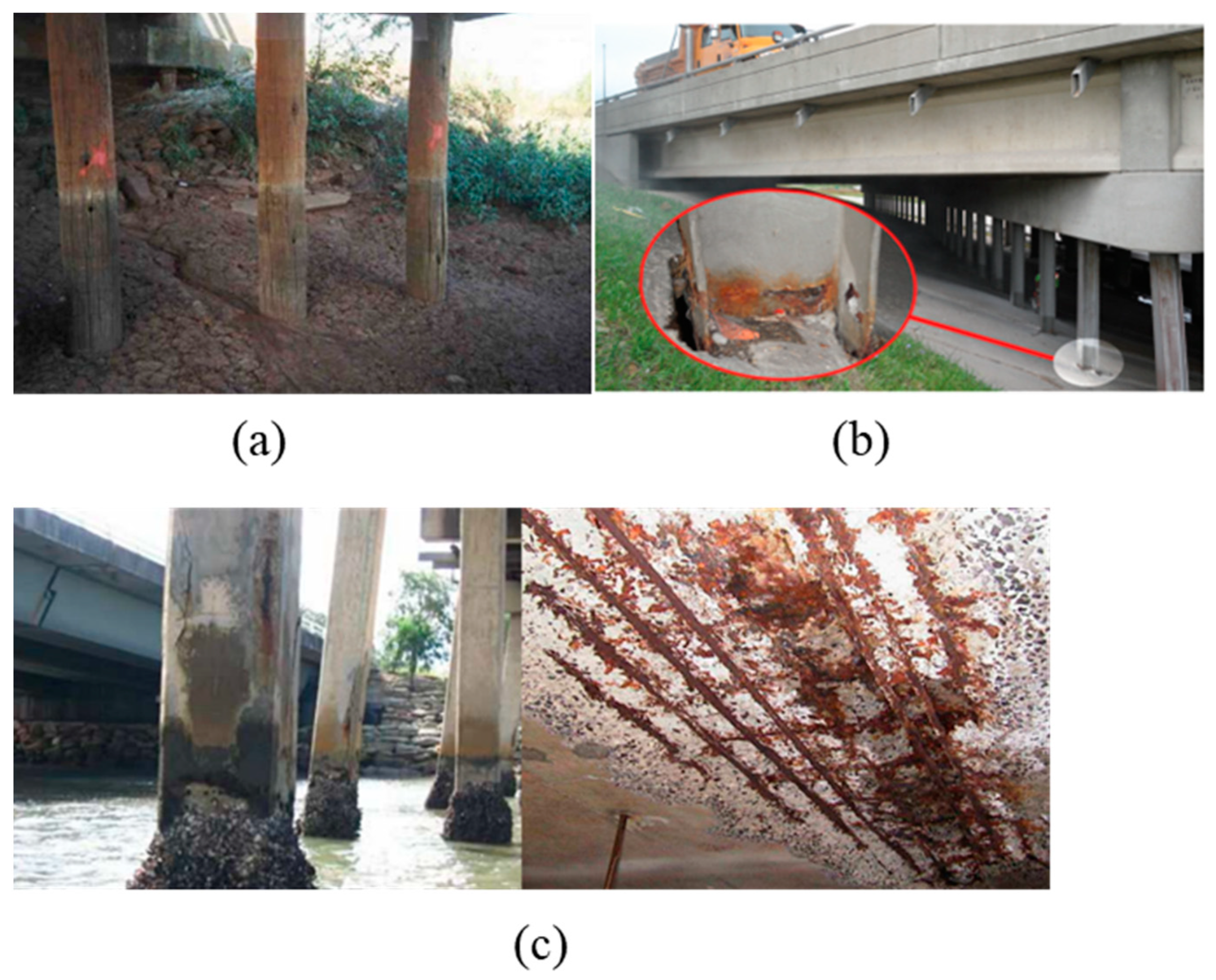
Driven piles are generally categorized into timber, steel, concrete, and composite piles. These piles have been adopted in many pile foundation projects for bridges and buildings. Timber piles provide a green method of construction; however, their application has been limited as they experience significant deterioration due to the fungal decay of the wood; an example is shown in
Figure 1a [
18]. The use of steel piles always raises the issue of corrosion [
19] affecting their performance during service. An example of steel pile corrosion observed in one of the bridges in Missouri is shown in
Figure 1b [
20]. On the other hand, although composite piles provide good durability and service performance, their application has been limited due to the high cost for their production and installation. Among all types of driven piles, concrete piles, specifically prestressed–precast concrete piles (PPCPs), are the most common ones used in foundation projects [
21]. Recent studies indicate that PPCPs have a tendency to crack during driving due to the presence of large tensile stresses; they can also fail due to the compressive stress developed using a large driving hammer [
22,
23]. Cracking can also occur in concrete piles due to the corrosion of embedded steel reinforcement bars and prestressing strands, and exposure to contaminated groundwater or seawater can initiate chemical deterioration that leads to cracking [
24,
25]. An example of concrete deterioration is shown in
Figure 1c [
26]. To address these issues, Ultra-High-Performance Concrete (UHPC) piles have recently been developed. The research findings on the use of these piles are explained in the following sections.
Comparison of Various Available Driven Piles Used in Pile Foundation
Table 1 presents a summary of the advantages and disadvantages, as well as some applications, of various available driven piles used in pile foundation.
3. UHPC Piles
The Federal Highway Administration (FHWA) [
31] defines Ultra-High-Performance Concrete (UHPC) as a “cementitious composite material composed of an optimized gradation of granular constituents, a water-to-cementitious materials ratio less than 0.25, and a high percentage of discontinuous internal fiber reinforcement.” UHPC is typically distinguished from other types of concrete based on its mechanical performance. Accordingly, many other definitions of UHPC also include a minimum tensile strength and/or ductility requirement, and many also specify minimum durability criteria [
32,
33,
34,
35,
36,
37].
Because of the superior properties of UHPC materials, PPCPs using UHPC material promise to address the limitations of other piling solutions. The high strength of UHPC (117 MPa to 152 MPa) enables smaller sections and the more efficient use of materials. Piles using UHPC have been used in marine environments due to durability associated with UHPC when compared with piles with other materials. Multiple studies on the durability of UHPC [
9,
10,
38,
39,
40] have reached the conclusion that UHPC class material is more durable than conventional concrete and can be used to extend the service life of concrete structures. UHPC piles have excellent lateral and axial stiffness due to their high elastic modulus of approximately 55,000 MPa, even when reduced sections are used. UHPC piles allow for the application of high prestressing and reduce the spacing between strands [
41]. Voort et al. [
42] report that UHPC piles can be driven with more ease than conventional piles.
Current research typically considers developing UHPC pile standards for use as either a direct replacement for or a higher performance option in comparison with currently available conventional concrete and steel H-pile standards. UHPC piles developed as direct replacements aim to have similar or improved moment capacity, weight, and driveability compared with currently used steel H-pile or conventional precast–prestressed concrete pile options.
UHPC plies come in different shapes and configurations. The common shapes are square, cylinder, H-shaped, modified H-shaped, and octagonal. Various institutions in the concrete industry are standardizing their manufacturing specifications and designs at present.
3.1. Previous Research on UHPC Piles
UHPC pile research to date has mostly aimed at developing UHPC pile details to replace steel H-piles. A summary of the UHPC pile cross-sections that have been or are currently being investigated is shown in
Figure 2 [
13,
43] and
Figure 3. There is ongoing research by the Alabama Department of Transportation (ALDOT) and the Prestressed/Precast Concrete Institute (PCI) investigating prestressed UHPC H-piles; these works are investigating 12-inch (305 mm), 14-inch (355.6 mm), and 16-inch (406 mm) UHPC H-piles with high precompression.
Figure 2b [
43] shows the details of two of the UHPC H-pile sections.
Figure 2a [
13] shows a section of a completed research work conducted at Iowa State University.
The Florida Department of Transportation (FDOT) is currently investigating several UHPC piles with different shapes. The configuration and shape of some of the UHPC pile sections are shown in
Figure 3.
Voort et al. [
13] developed a tapered H-shaped UHPC pile section aimed at replacing an HP 10 × 57-inch (254 × 1448 mm) steel pile, as shown in
Figure 4 [
13]. The outside dimensions of the piles are almost identical, which allowed them to be driven using similar equipment.
The section properties of the UHPC and steel H-piles used in their study are shown in
Table 2. The UHPC piles had a much larger cross-sectional area and slightly heavier weight compared to steel H-pile.
The moment–axial load interaction diagrams for these UHPC H-piles and HP 10 × 57-inch (254 × 1448 mm) steel piles are shown in
Figure 5 [
13]. The axial load applied to generate 6 ksi (41 MPa) compressive stress in the piles is highlighted, as this was the axial stress limit used in the design in Iowa where the research was conducted. Voort et al. [
13] highlighted that although the moment capacity of the UHPC pile was less, the axial load at 6 ksi (41 MPa) axial stress is over three times greater for the UHPC pile compared to steel H-pile. They mentioned that the axial capacity is more significant since it typically controls the design.
Garder et al. [
41] also investigated the cracking performance of UHPC piles, as the piles would lose their long-term durability performance if cracking was to occur. They assumed a strain versus crack width relationship, as shown in
Figure 6 [
13,
41]. Based on the results from Voort et al. [
13] for the strains when micro-cracking started, cracking started when cracks exceeded 0.012 in. (0.305 mm).
They also compared the moment curvature analysis results for both UHPC and HP 10 × 57-inch (254 × 1448 mm) piles at strong and weak axis bending for four different axial load cases. They suggested that the service moment should be considered for UHPC pile design to ensure that cracking does not occur in UHPC piles in service [
41].
3.2. UHPC Pile Application in Foundation Construction
UHPC piles have already been used in several construction projects. They were used for one abutment for Lily River Detour Bridge (Highway 11) in Ontario, Canada, in 2020 [
45]. One abutment utilized UHPC H-piles, and the other abutment implemented steel H-piles with the same outside dimensions. Photographs of the bridge during construction are shown in
Figure 7 [
45].
The Florida Department of Transportation (FDOT) [
46] included a 30-inch (762 mm) UHPC H-pile in the CR 339 over Waccasassa River Bridge. The 30-inch (762 mm) UHPC H-pile was used as a substitute for a 20-inch (508 mm) square prestressed concrete pile that was used for the rest of the piles in the structure. Photographs of the driving process are shown in
Figure 8 [
46].
Garder et al. [
41] reported the field implementation of a single UHPC H-pile on a bridge project in Sac County, Iowa, near the intersection of US 20 over US 71. The bridge has three spans, a total length of 6.1 m, 12.2 m width, and 24-degree skew. The lifting and installation process is illustrated in
Figure 9 [
41].
4. UHPC Pile Splices
During construction, for various reasons, it may be beneficial or necessary to cast piles with shorter lengths and splice them at the site to form a longer pile length. In preplanned situations, piles may be equipped in advance with connection parts and devices to facilitate splicing at the site. In unplanned situations, piles may be joined with more efforts at the site involving drilling and other modifications. Pile splice must be capable of resisting stresses induced by driving and service loads. Splices should be effective without a significant increase in the project time, be durable, and cost effective [
41].
In the next section, the available splicing methods that can be applied to UHPC piles are reviewed. Accordingly, it first discusses the splicing technique that is solely developed for UHPC piles. Then, it explores some of the splicing methods that have been developed for conventional PPCPs in general but can also be implemented for UHPC piles. Lastly, some new splicing systems [
47,
48,
49,
50] using advanced materials such as fiber-reinforced polymer (FRP) sheet or jacket, Near-Surface-Mounted (NSM) FRP, and the use of mechanical couplers are introduced.
4.1. Previous Work on UHPC Pile Splice
Garder et al. [
41] developed a splice detail for UHPC piles involving a steel embedment in the ends of each pile, shown in
Figure 10 [
41], with field welding of the embedment on both sides to create the splice. The splice was designed to develop the full moment and shear capacity of the UHPC pile section. They adopted the welded pile splice option, which is typically common to steel H-pile splice, so there were no concerns with field welding being a new practice for splicing UHPC piles.
Garder et al. [
41] tested the developed splice detail in direct tension, flexure, and shear. The specimen failed in the initial direct tension test at a load of 103 kips (458 kN), 27.4% of the unspliced pile tension capacity, toward one of the supports (outside of the splice region).
The failure of the test specimens occurred due to the fracture of the weld between the corner angle and the 0.5-inch (12.7 mm) end plate of the pile splice, shown in
Figure 11 [
41]. It was concluded that the shop welding at the precast plant had a shorter length between the corner angle and end plate than specified, which led to the failure of the splice. They recommend a full penetration weld between the edge angles and end plate.
At the time of writing, this is the sole published work on the welded splice method for UHPC pile.
4.2. Other PPCP Splices Applicable to UHPC Piles
Splice systems that have been used for conventional PPCPs and can be further implemented for UHPC piles are discussed in this section.
4.2.1. Bolted Splices
The Japanese bolted splice discussed by Bruce and Hebert [
15] includes an embedded end plate with threaded rods extending into the splice region and creating the field splice, as shown in
Figure 12 [
15]. The end plates have recesses in the concrete that provide spaces for tightening the bolt hex nuts and threaded rods.
Another type of bolted connection is the NU chuck splice system, shown in
Figure 13 [
17,
51]. This system also has strands anchored to the end plates, with the splicing of piles occurring through large threaded rods and four hex nuts. Experimental research showed that the splices could reach sufficient capacity, but a brittle failure mechanism and strand slippage at the end plates were observed [
17,
51].
This splicing method can satisfy the required capacity, and the main disadvantage is that the recess area in the concrete restricts the configuration of the strands.
4.2.2. Epoxy-Bonded Dowel Splices
Epoxy-bonded dowel splices are created by casting or drilling holes in the top of the lower pile to receive dowel rebars protruding out of the lower end of the upper pile. Dowel bars can be made of carbon steel, stainless steel (SS), carbon fiber-reinforced polymer (CFRP), or glass fiber-reinforced polymer (GFRP). The dowel rebars must have adequate length to bond with the other pile segment. Different types of resin and cementitious grouts can be used as filler and bonding agents to connect the pile segments [
52,
53].
Corrosion-resistant dowel bars are often chosen as they can increase the durability of pile splices [
54]. One drawback of this splice type is that the epoxy must be cured before driving of the spliced pile can resume to ensure that the pile splice has sufficient tensile strength. This can be overcome by placing a cushion between the pile segments and continuing to drive while the epoxy is still wet [
14]. Also, the in-place flexural strength of the pile splices is limited for this option, especially in an unplanned situation. An example of an epoxy dowel pile splice is shown in
Figure 14 [
53].
This method is commonly used for splicing in the field and requires low material and labor. Epoxy-bonded dowel splices are the most common splicing technique used in the state of Florida [
14].
4.2.3. Post-Tensioned Splices
Post-tensioning ducts can be used to form a connection between two pile segments. Splice is achieved by running post-tensioning strands through this duct across the two-pile segment. The strands are then tensioned and stressed to form connections. Post-tensioned splices can increase the tensile capacity near the ends of the prestressed pile and the splice region [
52] and provide good bending and tensile strengths [
17]. Mullins and Sen [
14] developed a post-tensioned splice detail where embedded anchors are provided in the ends of the piles (dually embedded anchors), as shown in
Figure 15 [
14].
For this detail, strands were inserted into the anchors on each side, see
Figure 16a [
14], and then post-tensioned from the end of the top pile, see
Figure 16b [
14]. The post-tensioned strands were grouted after tensioning.
Some drawbacks associated with this splice option usage are that it is susceptible to corrosion, and this limits its implementation in marine environments, the cost of materials and the technicality involved makes it an expensive option, and it will be difficult to use in unplanned situations [
14,
17,
55].
4.2.4. Fiber-Reinforced Polymer (FRP) Sheet/Jacket
The FRP sheet/jacket concept has been introduced by Khedmatgozar Dolati and Mehrabi [
47,
50] as an innovative alternative to the existing methods for connecting driven pile segments both in preplanned and unplanned situations. The splicing system consists of an alignment bar and FRP sheet (layers of carbon fiber-reinforced polymer or glass fiber polymer), which are bonded to the pile segment with resin/epoxy, as presented in
Figure 17a [
47].
The FRP material can also be made in a jacket form with four sides already connected like a box. In a preplanned situation, the jacket can be pre-fitted and pre-attached to the upper pile segment at the precast plant, as illustrated in
Figure 17b [
47]. To account for the shear resistance, confinement, and premature pealing of FRP, bi-directional FRP strips can be used as shown in this figure. In preplanned situations, concrete can be recessed in the splicing area to avoid a larger cross-section for splice in the case of soils with frictional resistance. The system has excellent corrosion resistance.
4.2.5. Near-Surface-Mounted Fiber-Reinforced Polymer (NSM FRP)
For this method, external grooves are cut and installed with FRP (or other material) bars and bonded to the concrete pile with epoxy adhesives to create connections, as shown in
Figure 18 [
48]. The grooves can be cut in or formed during casting. An alignment bar is used between the two pile segments [
48,
49,
56]. The alignment holes and segment interfaces are sealed with epoxy or other bonding agents. NSM FRP splice offers an economical, labor friendly, durable option for pile-splicing and can be used in both unplanned and planned pile-splicing situations.
4.2.6. Mechanical Coupler
In this connection system, sleeves (coupler) are inserted into the lower pile segment and are connected to the upper segment by splicing steel reinforcement. The space between the bars and sleeve is filled with grouts. There are different types of couplers available on the market, which include shear screw couplers, headed bar couplers, grouted sleeve couplers, threaded couplers, and swaged couplers [
17,
57,
58,
59]. The most common type of mechanical couplers are grouted splice couplers, as shown in
Figure 19 [
60].
Handling and installation are easier with this method, and it is an economical alternate method to other available options. Due to the advance preparation needed in the lower segment of the pile, this connection system is suitable only for preplanned situations, and it can fully develop the required strength needed for this situation.
5. Discussion
This paper examines various forms of driven piles utilized in the construction of pile foundations. The UHPC pile is a viable alternative to traditional piles (such as timber, steel, concrete, and composite piles) due to its superior durability, performance, and driveability. UHPC piles in different forms have been effectively devised and employed in numerous projects, with other projects exploring UHPC as a possible alternative for conventional steel piles or PPCPs.
After reviewing the existing choices, many pile-splicing methods suitable for UHPC piles have been identified. These pile-splicing methods may be regarded as a viable choice for UHPC piles if they satisfy the standard requirements for the strength of pile splices in both preplanned and unplanned situations. Welded, bolted, post-tensioned, epoxy-bonded dowel, FRP sheet or jacket, NSM FRP, and mechanical coupler pile splice methods have been studied, and a comparison of these options is presented in
Table 3 based on the following criteria:
Unplanned situation: the possibility to perform the splice system in an unforeseen situation.
Capacity: the system’s ability to resist the required level of tension, compression, and flexure.
Preparations: the time and effort for preparing before installation of the system.
Installation: the time and effort for installation of the system.
Durability: system functionality in extreme conditions, such as a corrosive environment.
Cost: the system’s overall cost in terms of manufacturing and installation.
Numerous variables influence the pile-splicing technique selected for a given project, including materials, cost, construction feasibility, and method of construction schedule. Diverse pile splice methods may be integrated to accomplish the design objective.
6. Conclusions
This study aimed to explore options for connecting segments of Ultra-High-Performance Concrete (UHPC) piles in planned and unplanned scenarios. After reviewing the driven piles, this paper thoroughly investigated splicing systems for UHPC piles, assessing prior research and field applications. The applicable splices were then introduced and evaluated based on criteria like capacity, durability, affordability, and ease of application. The following main conclusions can be drawn:
Pile-splicing is necessary to join two segments of piles during driving; the advantages relate to reduction in installation and transportation time and preventing damage to precast concrete during construction.
Welded, bolted, post-tensioning, epoxy-bonded dowel, FRP sheet/jacket, NSM FRP, and mechanical coupler were identified to have the potential for use in splicing UHPC piles.
All identified pile-splicing options can be used in preplanned situations. However, epoxy-bonded dowel, FRP sheet/jacket, and NSM FRP can also be utilized in the case of unplanned situations on the field.
FRP sheet/jacket and NSM FRP pile splice options have a good corrosion resistance that is especially in demand in corrosive environments.
Mechanical coupler is very easy to install and is quick. Welded, bolted, epoxy-bonded dowel, FRP sheet/jacket, and NSM FRP are other options that require moderate time for installation.
Welded, epoxy-bonded dowel, FRP sheet/jacket, NSM FRP, and mechanical coupler have a low cost of production.
FRP sheet/jacket method takes less time to prepare compared to other options. Welded, bolted, epoxy-bonded dowel, FRP sheet/jacket, and NSM FRP are other options that take a moderate amount of time to prepare.
7. Recommendation for Future Research
Ultra-High-Performance Concrete (UHPC) as a pile material is a relatively new innovative material, and the standard guidelines for design and construction are currently at different advanced stages with regulatory institutions in the concrete industry. To provide enough guidelines for the analysis and design of UHPC piles splices, various splice system designs must consider the characteristics of UHPC class materials.
As driveability during construction is a significant concern with conventional concrete, it is necessary to investigate the driveability of UHPC piles with pile splices. Additionally, the debonding effect of Fiber-Reinforced Polymer (FRP) materials during pile driving and the effects of soil friction on spliced piles need to be investigated. Also, the shear capacity of the UHPC pile splice section is another topic to investigate.
Several of the splice systems reviewed in this paper have not been tested adequately in the laboratory and the field. Therefore, future experimental work is recommended for those systems.
Author Contributions
Conceptualization, M.O., S.S.K.D., A.M. and D.G.; methodology, M.O., S.S.K.D., A.M. and D.G.; software, M.O. and S.S.K.D.; formal analysis, M.O., S.S.K.D., A.M. and D.G.; investigation, M.O., S.S.K.D., A.M. and D.G.; resources, M.O., S.S.K.D., A.M. and D.G.; data curation M.O., S.S.K.D. and A.M.; writing—original draft preparation, M.O., S.S.K.D., A.M. and D.G.; writing—review and editing, M.O., S.S.K.D., A.M. and D.G.; visualization, M.O., S.S.K.D. and A.M.; supervision, A.M. All authors have read and agreed to the published version of the manuscript.
Funding
This research was funded by the Florida Department of Transportation (FDOT), grant number BED29 977-03.
Data Availability Statement
Not applicable.
Acknowledgments
This project for which this study was performed is supported by the Florida Department of Transportation (FDOT). The opinions, findings, and conclusions expressed in this publication are those of the author(s) and not necessarily those of the Florida Department of Transportation or the U.S. Department of Transportation.
Conflicts of Interest
The authors declare that they have no known competing financial interests or personal relationships that could have appeared to influence the work reported in this paper.
References
- Pando, M.A.; Ealy, C.D.; Filz, G.M.; Lesko, J.J.; Hoppe, E.J. A Laboratory and Field Study of Composite Piles for Bridge Substructures; Federal Highway Administration: Honolulu, HI, USA, 2006. [Google Scholar]
- Russell, H.G.; Graybeal, B.A. Ultra-High Performance Concrete: A State-of-the-Art Report for the Bridge Community; FHWA-HRT-13-060; Federal Highway Administration (FHWA): Honolulu, HI, USA, 2013. [Google Scholar]
- Graybeal, B.A. Material Property Characterization of Ultra-High Performance Concrete; FHWA: Honolulu, HI, USA, 2006. [Google Scholar]
- El-Tawil, S.; Tai, Y.-S.; Ii, J.A.B.; Rogers, D. Open-Recipe Ultra-High- Performance Concrete. Concr. Int. 2020, 42, 33–38. [Google Scholar]
- Shahrokhinasab, E.; Garber, D. Development of ‘ABC-UTC Non-Proprietary UHPC’ Mix. Miami, Final Report ABC-UTC-2016-C2-FIU01-Final; Florida International University: Miami, FL, USA, 2021. [Google Scholar]
- Schmidt, M.; Fehling, E. (Eds.) Ultra high performance concrete (UHPC): Proceedings of the International Symposium on Ultra High Performance Concrete, Kassel, Germany, 13–15 September 2004. In Schriftenreihe Baustoffe und Massivbau; No. Heft 3; Kassel University Press: Kassel, Germany, 2004. [Google Scholar]
- Graybeal. Development of Non-Proprietary UHPC for Use in Highway Bridge Sector; FHWA: Honolulu, HI, USA, 2013. [Google Scholar]
- Giesler, A.J.; Applegate, S.B.; Weldon, B.D. Implementing Nonproprietary, Ultra-High-Performance Concrete in a Precasting Plant. PCI J. 2016, 61, 68–80. [Google Scholar] [CrossRef]
- Abbas, S.; Nehdi, M.L.; Saleem, M.A. Ultra-High Performance Concrete: Mechanical Performance, Durability, Sustainability and Implementation Challenges. Int. J. Concr. Struct. Mater. 2016, 10, 271–295. [Google Scholar] [CrossRef]
- Yan, P.-Y. Development and Present Situation of Ultra-high Performance Concrete (UHPC) Concrete. Concr. World 2010, 9, 36–41. [Google Scholar] [CrossRef]
- Arora, A.; Yao, Y.; Mobasher, B.; Neithalath, N. Fundamental insights into the compressive and flexural response of binder- and aggregate-optimized ultra-high performance concrete (UHPC). Cem. Concr. Compos. 2019, 98, 1–13. [Google Scholar] [CrossRef]
- Berry, M. Feasibility of Non-Proprietary Ultra-High Performance Concrete (UHPC) for Use in Highway Bridges in Montana: Phase II Field Application; Montana Department of Transportation: Missoula, MT, USA, 2018. [Google Scholar]
- Voort, T.V.; Suleiman, M.; Sritharan, S. Design and Performance Verification of Ultra High Performance Concrete Piles for Deep Foundations; Iowa Department of Transportation: Iowa, IA, USA, 2008. [Google Scholar]
- Mullins, G.; Sen, R. Investigation and Development of an Effective, Economical and Efficient Concrete Pile Splice (Final Report); Florida Department of Transportation: Tallahassee, FL, USA, 2015. [Google Scholar]
- Bruce, R.N.; Hebert, D.C. Splicing of Precast Prestressed Concrete Piles: Part I—Review and Performance of Splices. PCI J. 1974, 19, 70–97. [Google Scholar] [CrossRef]
- Venuti, W.J. Efficient Splicing Technique for Precast Prestressed Concrete Piles. PCI J. 1980, 25, 102–124. [Google Scholar] [CrossRef]
- Dolati, S.S.K.; Mehrabi, A. Review of available systems and materials for splicing prestressed-precast concrete piles. Structures 2021, 30, 850–865. [Google Scholar] [CrossRef]
- Emerson, R.N. In Situ Repair Technique for Decayed Timber Piles. In Structures 2004; American Society of Civil Engineers: Nashville, TN, USA, 2004; pp. 1–9. [Google Scholar] [CrossRef]
- Ohsaki, Y. Corrosion of steel piles driven in soil deposits. Soil Found 1982, 22, 37–76. [Google Scholar]
- Ehsani, M.; Croarkin, M. Missouri DOT Pioneers the Implementation of the Next Generation of FRP Products. Available online: https://pilemedic.com/wp-content/uploads/2023/02/a-novel-solution-for-restoration-of-deteriorated-piles.pdf (accessed on 15 November 2023).
- Grand, B.A. Types of Piles: Their Characteristics and General Use. In Proceedings of the 49th Annual Meeting of the Highway Research Board, Washington, DC, USA, 12–16 January 1970. [Google Scholar]
- Richardson, J.G. Supervision of Concrete Construction; Taylor & Francis: Abingdon, UK, 1986; Volume 1. [Google Scholar]
- Salgado, R. The Engineering of Foundations; McGraw-Hill Education: New York, NY, USA, 2006. [Google Scholar]
- Shaia, H.A. Behaviour of Fibre Reinforced Polymer Composite Piles: Experimental and Numerical Study; University of Manchester: Manchester, UK, 2013. [Google Scholar]
- Suleiman, M.T.; Voort, T.V.; Sritharan, S. Behavior of Driven Ultrahigh-Performance Concrete H-Piles Subjected to Vertical and Lateral Loadings. J. Geotech. Geoenviron. Eng. 2010, 136, 1403–1413. [Google Scholar] [CrossRef]
- Wang, X.; Nguyen, M.; Stewart, M.G.; Syme, M.; Leitch, A. Analysis of Climate Change Impacts on the Deterioration of Concrete Infrastructure—Part 1: Mechanisms, Practices, Modelling and Simulations—A Review; CSIRO: Canberra, Australia, 2010. [Google Scholar]
- Abebe, A.; Smith, D.I.G. Pile Foundation Design: A Student Guide; Napier University: Edinburgh, UK, 1999. [Google Scholar]
- Sharma, R. Feasibility Studies on the Design and Usage of Steel Pipe Piles for ALDOT BRidges.pdf; Auburn University: Auburn, AL, USA, 2023. [Google Scholar]
- Zyka, K.; Mohajerani, A. Composite piles: A review. Constr. Build. Mater. 2016, 107, 394–410. [Google Scholar] [CrossRef]
- Iskander, M.G.; Hassan, M. State of the practive review in FRP composite piling. J. Compos. Constr. 1998, 2, 116–120. [Google Scholar] [CrossRef]
- Graybeal, B.; El-Helou, R.G. Development of an AASHTO Guide Specification for Ultra-High Performance Concrete. In High Performance Concrete; Iowa State University Digital Press: Iowa, IA, USA, 2019. [Google Scholar]
- Ultra-High-Performance Concrete: An Emerging Technology Report (ACI 239R-18); American Concrete Institute: Farmington Hills, MI, USA, 2018.
- ASTM-C1856-C1856M-17; Standard Practice for Fabricating and Testing Specimens of Ultra-High Performance Concrete. American Society for Testing and Materials (ASTM): West Conshohocken, PA, USA, 2017.
- Graybeal, B. Design and Construction of Field-Cast UHPC Connections; Federal Highway Administration: Honolulu, HI, USA, 2014. [Google Scholar]
- Tadros, M.; Lawler, J. Implementation of Ultra-High Performance Concrete in Long-Span Precast Pretensioned Elements for Concrete Buildings and Bridges; Precast/Prestressed Concrete Institute: Chicago, IL, USA, 2021. [Google Scholar] [CrossRef]
- Canadian Standards Association. CSA A23.1 Concrete materials and methods of concrete construction, Annex U—Ultra-high Performance Concrete (UHPC); Mississauga, Ontario. Canadian Standard Association: Toronto, AB, Canada, 2019. [Google Scholar]
- Swiss Society of Engineers and Architects (SIA). SIA 2052 Béton Fibré Ultra-Performant (BFUP)—Matériaux, Dimensionnement et Exécution (Ultra-High Performance Fibre Reinforced Cement-Based Composites [UHPFRC]-Construction Material, Dimensioning and Application); Swiss Society of Engineers and Architects (SIA): Zurich, Switzerland, 2016. [Google Scholar]
- Wang, B. Corrosion Behavior of Corrosion-Resistant Steel Reinforcements in High and Ultra-High Performance Concrete in Chloride Attack Environments; University of Houston: Houston, TX, USA, 2019. [Google Scholar]
- Roux, N.; Andrade, C.; Sanjuan, M.A. Experimental Study of Durability of Reactive Powder Concretes. J. Mater. Civ. Eng. 1996, 8, 1–6. [Google Scholar] [CrossRef]
- Mostafa, S.A.; EL-Deeb, M.M.; Farghali, A.A.; Faried, A.S. Evaluation of the nano silica and nano waste materials on the corrosion protection of high strength steel embedded in ultra-high performance concrete. Sci. Rep. 2021, 11, 2617. [Google Scholar] [CrossRef]
- Garder, J.; Aaleti, S.; Zhong, L.; Sritharan, S. Connection Details and Field Implementation of UHPC Piles—Phase II; IHRB Project TR-615; Iowa Department of Transportation: Iowa, IA, USA, 2019. [Google Scholar]
- Voort, T.L.V.; Sritharan, S.; Suleiman, M. A precast uhpc pile for substructural applications. In Proceedings of the PCI National Bridge Conference, 53rd PCI Annual Convention, Phoenix, AZ, USA, 22–24 October 2007. [Google Scholar]
- Smart Up UHPC. ALDOT Researching UHPC for H-Piles. 2023. Available online: https://www.smartupuhpc.com/case-studies/aldot-investigating-use-of-uhpc-h-piles (accessed on 1 March 2023).
- Sritharan, S.; Aaleti, S. Experimental and Analytical Investigation of UHPC Pile-to-Abutment Connections. In First International Interactive Symposium on UHPC; Iowa State University Digital Press: Iowa, IA, USA, 2016. [Google Scholar] [CrossRef]
- Walbridge, S.; Nik-Bakht, M.; Ng KT, W.; Shome, M.; Alam, M.S.; El Damatty, A.; Lovegrove, G. (Eds.) Proceedings of the Canadian Society of Civil Engineering Annual Conference 2021: CSCE21 General Track Volume 1. In Lecture Notes in Civil Engineering; Springer Nature: Singapore, 2023; Volume 239. [Google Scholar] [CrossRef]
- Transportation, F.D.O. FDOT Transportation Innovation Initiative: UHPC—Design Innovations. Available online: http://www.fdot.gov/structures/innovation.shtm (accessed on 13 February 2020).
- Dolati, S.S.K.; Mehrabi, A. FRP sheet/jacket system as an alternative method for splicing prestressed-precast concrete piles. Case Stud. Constr. Mater. 2022, 16, e00912. [Google Scholar]
- Dolati, S.S.K.; Mehrabi, A. NSM FRP Pile-Splice System for Prestressed Precast Concrete Piles. Pract. Period. Struct. Des. Constr. 2022, 27, 04022046. [Google Scholar] [CrossRef]
- Mehrabi, A.; Dolati, S.S.K. NSMB Pile Splice System for Precast Concrete Piles. U.S. Patent 11,319,689, 3 May 2022. [Google Scholar]
- Mehrabi, A.; Dolati, S.S.K. FRP Splice System for Joining Structural Elements. U.S. Patent 11,319,706, 3 May 2022. [Google Scholar]
- Ansley, M.; Abalo, V.; Potter, W. Testing Square Precast Concrete Pile Splices; Florida Department of Transportation (FDOT): Tallahassee, FL, USA, 2011. [Google Scholar]
- Mullins, G.; Johnson, K.; Sen, R. Post-Tensioned Splice System for Precast, Prestressed Concrete Piles: Part 1, Conceptual design. PCI J. 2018, 63, 26–39. [Google Scholar] [CrossRef]
- Wu, Z.; Johnson, K.; Mullins, G.; Sen, R. Post-Tensioned Splice System for Precast, Prestressed Concrete Piles: Part 3, Capacity Verification from Laboratory and Full-Scale Testing. PCI J. 2018, 63, 19–35. [Google Scholar] [CrossRef]
- Mehrabi, A.; Farhangdoust, S.; Dolati, S.S.K.; Tabiatnejad, D.; Lee, S.J.; Garber, D. Epoxy-Dowel Pile Splice Evaluation (FDOT Report); Florida Department of Transportation: Tallahassee, FL, USA, 2022. [Google Scholar]
- Wu, Z. Effective Post-Tensioned Splicing System for Prestressed Concrete Piles. University of South Florida. 2016. Available online: https://digitalcommons.usf.edu/cgi/viewcontent.cgi?article=7802&context=etd (accessed on 5 February 2023).
- Dolati, S.S.K.; Mehrabi, A. Two New Methods for Establishing Simple Yet Durable Connection System for Precast Elements. In Structures Congress 2023; American Society of Civil Engineers: Reston, VA, USA, 2023; pp. 293–303. [Google Scholar]
- Coogler, K.L.; Harries, K.A.; Gallick, M. Evaluation of Offset Mechanical Reinforcing Bar Splice Systems; University of Pittsburgh: Pittsburg, PA, USA, 2006. [Google Scholar]
- Korin, U.; Kalman, G. Mechanical Splicer for Precast, Prestressed Concrete Piles. PCI J. 2004, 49, 78–85. [Google Scholar] [CrossRef]
- Dolati, S.S.K.; Mehrabi, A. Alternative Systems and Materials for Splicing Prestressed-Precast Concrete Piles. Transp. Res. Rec. 2021, 036119812110529. [Google Scholar] [CrossRef]
- Henin, E.; Morcous, G. Non-proprietary bar splice sleeve for precast concrete construction. Eng. Struct. 2015, 83, 154–162. [Google Scholar] [CrossRef]
- Gamble, W.L.; Bruce, R.N. Tests of 24 in. Square Prestressed Piles Spliced with ABB Splice Units. PCI J. 1990, 35, 56–73. [Google Scholar] [CrossRef]
| Disclaimer/Publisher’s Note: The statements, opinions and data contained in all publications are solely those of the individual author(s) and contributor(s) and not of MDPI and/or the editor(s). MDPI and/or the editor(s) disclaim responsibility for any injury to people or property resulting from any ideas, methods, instructions or products referred to in the content. |
© 2024 by the authors. Licensee MDPI, Basel, Switzerland. This article is an open access article distributed under the terms and conditions of the Creative Commons Attribution (CC BY) license (https://creativecommons.org/licenses/by/4.0/).


