Article

Conversion of a Small-Size Passenger Car to Hydrogen Fueling: 0D/1D Simulation of EGR and Related Flow Limitations

by
Adrian Irimescu
1,*,
Bianca Maria Vaglieco
1,
Simona Silvia Merola
1,
Vasco Zollo
2 and
Raffaele De Marinis
2
1
Institute of Science and Technology for Sustainable Energy and Mobility STEMS-CNR, Via G. Marconi 4, 80125 Naples, Italy
2
Demax SRL, Strada Statale 7 Appia km 251, 82014 Ceppaloni, Italy
*
Author to whom correspondence should be addressed.
Appl. Sci. 2024, 14(2), 844; https://doi.org/10.3390/app14020844
Submission received: 18 December 2023 / Revised: 12 January 2024 / Accepted: 16 January 2024 / Published: 19 January 2024
(This article belongs to the Section Mechanical Engineering)

Abstract

:
Hydrogen is seen as a prime choice for complete replacement of gasoline so as to achieve zero-emissions energy and mobility. Combining the use of this alternative fuel with a circular economy approach for giving new life to the existing fleet of passenger cars ensures further benefits in terms of cost competitiveness. Transforming spark ignition (SI) engines to H2 power requires relatively minor changes and limited added components. Within this framework, the conversion of a small-size passenger car to hydrogen fueling was evaluated based on 0D/1D simulation. One of the methods to improve efficiency is to apply exhaust gas recirculation (EGR), which also lowers NOx emissions. Therefore, the previous version of the quasi-dimensional model was modified to include EGR and its effects on combustion. A dedicated laminar flame speed model was implemented for the specific properties of hydrogen, and a purpose-built sub-routine was implemented to correctly model the effects of residual gas at the start of combustion. Simulations were performed in several operating points representative of urban and highway driving. One of the main conclusions was that high-pressure recirculation was severely limited by the minimum flow requirements of the compressor. Low-pressure EGR ensured wider applicability and significant improvement of efficiency, especially during partial-load operation specific to urban use. Another benefit of recirculation was that pressure rise rates were predicted to be more contained and closer to the values expected for gasoline fueling. This was possible due to the high tolerance of H2 to the presence of residual gas.

1. Introduction

Forecasts for the future of passenger car propulsion predict that battery electric vehicles will be dominant [1]. A valid alternative is to use hydrogen as an energy carrier [2], with significant benefits in terms of employing/adapting existing infrastructure. The properties of this fuel render it a zero-carbon energy conversion solution (i.e., it contains only hydrogen atoms in its molecules) with a high mass-based energy density of 120 MJ/kg, a wide flammability range of 4 to 76%vol, and a laminar flame speed around 10 times higher at ambient pressure temperature compared to other fuels such as gasoline [3]. Internal combustion engines (ICEs) fueled with hydrogen may play an important part in heavy-duty applications [4], given that range requires a high weight/volume of batteries. On the other hand, converting the legacy fleet to H2 power is a valid approach for achieving zero-GHG emissions with minimum cost.
The use of hydrogen in ICEs raises many issues that need to be covered, with combustion properties being one of the defining aspects [5,6]. Improved efficiency is ensured by high laminar flame speed, along with better stability [7], whereas pressure rise rate limits constrain power density [8]. This parameter is also influenced by lower volumetric efficiency [9] compared to “classic” fuels, resulting in the need to apply super- or turbo-charging. Direct injection further improves performance [10] and reduces the risk of backfire [11]. Port fuel injection (PFI), on the other hand, maximizes fuel tank emptying and does not require a dedicated high-pressure pump; one important issue is that injector placement needs to be carefully assessed [12] in order to minimize the chances of causing abnormal combustion [13]. Even if all of these aspects highlight several difficulties of applying hydrogen fueling in ICEs, a demonstration of close-to-commercial H2 vehicles [14] has shown that practically zero emissions is possible.
One particular property of H2 is that it has very good tolerance to dilution, be it with fresh air or exhaust gas recirculation (EGR) [15]. This is directly related to its high laminar flame speed [16], which allows the engine to be operated with relatively high concentrations of inert gas without significant effects on combustion stability. Even low concentrations of H2 used as an additional fuel can bring significant benefits for gasoline- [17,18] or biogas-based engines [19]. In addition to the benefits of ultra-lean operation [20] (well known for ensuring low NOx emissions [21]), EGR can improve combustion characteristics [22]; it also allows for the application of three-way catalytic converters, which is less complex than the after-treatment solutions required for lean fueling [23]. It has further beneficial effects with respect to margins for controlling abnormal combustion [24,25,26]. Recirculation can be employed as load control as well, with improved margins [27].
Within this context, the present work studies the specifics of converting a small-size passenger car to H2 operation. The approach is control oriented and based on 0D/1D simulations aimed at evaluating the benefits of applying EGR. Compared to previous versions of the model, the components related to gas recirculation were added and attention was paid to the residual gas effect, as well as thermal aspects directly linked with the application of EGR. Two recirculation configurations were under scrutiny in the form of high- and low-pressure recirculation. Apart from full-load characteristics, four conditions representative of urban and highway driving were considered. A wide range of EGR rates of up to 30% concentration in the intake manifold was investigated in light of the high tolerance of H2 to diluted combustion. Boosting requirements and combustion characteristics were analyzed and compared to gasoline fueling, which was taken as the reference.

2. Materials and Methods

The turbocharged SI engine considered for the study powers a two-seater vehicle weighting 720 kg. It outputs 40 kW peak power, which ensures a 135 km/h top speed. The overall concept feasibility was previously validated with respect to driving range and peak power operation [28]. A rough estimate of the range was found to be around 100 km with a 30 L H2 container at 700 bar (fitted alongside the 22 L OEM gasoline tank), which is comparable to the 130 km-range figure of the electric version of the vehicle [29]. An even higher range of around 170 km would be possible if the gasoline tank were substituted with H2 bottles [30] (of course, if all aspects related to gas line routing and safety were mitigated successfully).
The full-load condition was chosen as the starting point for the analysis. Urban and highway use was also considered by calculating equivalent engine output at 30, 50, 90, and 130 km/h constant vehicle speed. The passenger car features an automated manual gearbox, and a gear shift strategy of around 3000 rpm was taken as representative. Engine speed and load were calculated for each of the four vehicle velocity points. Given the purpose of the passenger car, urban driving is most likely, and even if the 2480, 3130, and 2940 rpm values used for 30, 50, and 90 km/h in 3rd, 4th, and 5th gear, respectively [30], seem elevated, they fit the aforementioned gear shift strategy designed to ensure acceptable vehicle dynamics with contained engine torque.
Figure 1 shows an overall layout of the power unit, with highlighted components and gas flow paths, including EGR. Table 1 shows its main specifications. The gas injectors are shown to be located upstream in the intake runners (only for illustration purposes), but the actual location in the simulations was considered close to the intake port.
A 0D/1D model was built using OEM data and measurements performed on a disassembled unit. The overall concept is that components are represented as combinations of simple volumes (e.g., series of pipes, splits, and so on) [31]. Figure 2 illustrates the overall model layout and the control-oriented approach, for which injection, ignition, wastegate, and EGR valve actuation was performed by PID controllers. Most model specifics are available in [28,30]. Basically, the control logic acts on the throttle during partial-load operation (while keeping a compressor pressure ratio of 1) and on the wastegate when boosting is required (with the throttle wide open). A compressor surge limit was implemented in the PID-turbo component, and the PID-spark element featured a target of 9 deg aTDC for the 50% MFB combustion-phasing parameter. A reduction in the spark advance was implemented as a limit in the PID controller when knocking was predicted.
Compared to previous versions of the model [28,30], the recirculation circuit was added (including routing components and valve), as well as a heat exchanger; this was chosen so as to minimize the negative effects of charge heating. Special attention was paid to modeling as accurately as possible the geometry of the intercooler and EGR cooling module so as to obtain results that included the related thermal effects as much as possible. Another modification was to more thoroughly define the compressor map based on data found in [32] so as to improve predictions close to the surge line.
Model validation was based only on the fact that the compressor pressure ratio was modeled very close to the 1.5 value specified by the turbocharger OEM for gasoline operation at full load. This was due to the fact that there were no measurements available. Nonetheless, the relative differences between different operating conditions still provide valuable insight into the effects of using EGR with H2 fueling.
One specific requirement of the model was to include fuel chemistry effects; therefore, the predictive EngCylCombSITurb combustion sub-model [31] was chosen. This was done by using the software’s built-in laminar flame speed correlation for gasoline and for hydrogen by applying the correlation found in [33], taken as representative of conditions usually found during combustion in SI engines. In addition, several applications of the correlation in CFD simulations were found to accurately model H2 combustion in stoichiometric and lean conditions [34], which was another reason for the aforementioned choice.
Another particular aspect that needed to be considered for this study was the effect of residual gas on combustion. This was implemented as a look-up table that changes the dilution exponent multiplier (DEM) in Equation (1),
f x r = 1 2.06 · x r 0.77 · D E M
which directly influences the laminar flame speed value calculated with Equation (2),
S L = B m + B Φ · Φ Φ m 2 · T u T r e f α · p p r e f β · f x r
where f(xr) is the dilution effect term; xr is the residual gas concentration; SL is the laminar flame speed in m/s; Bm and Bϕ are the maximum and roll-off values, respectively; Φ is the equivalence ratio; Φm is the value at maximum speed; Tu and Tref are the unburned mixture temperature and reference value in K, respectively; α and β are the temperature and pressure exponents, respectively; and p and pref are the in-cylinder and reference pressure measured in Pa, respectively.
More to the point, the code simply looks up a DEM value in each cycle based on Φ and xr so as to obtain the correct residual gas term expression when using hydrogen [35]. This is even more important for the intended use of EGR; more to the point, during non-recirculating operation, in-cylinder residual gas ranges from 3 to 17%, whereas with 30% EGR, this value goes up to 30–40%. For this reason, great care was taken to model the influence of EGR on combustion as closely as possible.

3. Results and Discussion

The starting point for the analysis was to evaluate the two EGR configurations, i.e., low- and high-pressure circuits. Figure 3 shows the full-load operating points at 3000 rpm and peak power (i.e., 5250 rpm) in the compressor map domain; more to the point, it illustrates how the compressor rpm–pressure ratio points shifted from the situation with gasoline fueling (dark blue points) to hydrogen without EGR (light green points) and then at the end of the longer arrows when operating with H2 at the maximum achievable recirculation level.
Evidently, the use of H2 required higher boost levels, which needed to be further augmented when also applying EGR. In the high-pressure (HP) configuration, the exhaust stream needed to be routed from upstream of the turbine; this had the advantage of a shorter circuit and avoided possible issues with impurities that could have damaged the compressor. On the other hand, this also reduced the flow to both components while requiring higher boost pressure to circulate the additional flow through the engine. Figure 3 illustrates this two-step passage (i.e., switching from gasoline to H2 and then applying EGR), which basically moved the operating point closer to the surge line. It also highlights the fact that low-pressure (LP) EGR tended to move the operating point to a more favorable region of the map, with higher compressor efficiency and away from the surge line (albeit with a longer circuit and possible complications). Initial evaluations of the actual space available in the engine bay for placing the EGR heat exchanger and other routing components revealed that both configurations were feasible, even if low-pressure recirculation required a longer circuit. Another advantage of the LP configuration is that lower pressure in the recirculation circuit favored implementation (i.e., even if the circuit is longer, low pressure can be more easily implemented). For these reasons, the LP version was considered for further analysis.
Simulations were performed throughout the engine speed range at full load in three configurations, i.e., gasoline (reference), H2 fueling, and H2 with LP EGR. The maximum recirculation potential was sought after; therefore, for the EGR case, the wastegate was simply kept closed and the EGR valve was used as a means of controlling the engine output. More to the point, the controller opened the recirculation valve once the imposed brake power was achieved so the compressor would aspirate air mixed with recirculated exhaust gas, resulting in a lower energy input.
Figure 4 shows the results for the three configurations. The model predicted that the same level of engine power (i.e., full-load OEM data) could be obtained in all three cases for a crankshaft speed of above 2500 rpm. Below this threshold, the boosting required for compensating the loss in volumetric efficiency could not be achieved when using H2. This was due to the fact that the model predicted surge margins close to zero and limited wastegate closure. Indeed, there was no EGR potential for this range (i.e., between 1000 and 2500 rpm). At the higher end of the engine speed range, significant EGR of close to 30% could be used. This figure is well within the dilution tolerance of hydrogen [36], and therefore, there should not be any issues with combustion stability.
As expected, there was a benefit in efficiency when switching from gasoline to hydrogen. Figure 5 shows that relative gains of up to 10% were predicted, mainly due to the fact that stoichiometric H2 operation was considered possible due to less evident knock limitations compared to gasoline. In other words, the properties of hydrogen that enable much faster flame propagation with respect to “classical” fuels were considered to fully mitigate possible auto-ignition phenomena. Even if the relatively simple approach of imposing a RON value of 130 in the knock sub-model cannot give detailed insight into such complex and highly stochastic phenomena, the fact that the model predicted a reduced auto-ignition tendency of hydrogen suggests that full-load lambda 1 operation could be possible.
Applying EGR ensured a further slight improvement in efficiency, especially in the mid-rpm and peak power region. Evidently, increased boost levels would be needed with an intake pressure of around 30% higher when switching from gasoline to H2 and of close to 60% when applying EGR. Such elevated manifold pressure (absolute values of close to 2.5 bar) is not uncommon in state-of-the-art automotive SI engines but would be a point to consider when evaluating the conversion of an existing power unit. More to the point, even if the turbine–compressor assembly were capable of operating in the region predicted to ensure the intended boost pressure for EGR, control limitations may prevent actual implementation. Therefore, the control system may require additional hardware modifications (e.g., the pneumatic actuator that controls the wastegate) and not just ECU remapping. The actual relative gain in efficiency of up to 3% compared to non-diluted operation is, however, another important positive aspect, especially as it can be achieved in the high-load region, i.e., most likely to be used during highway driving and therefore with a significant impact on vehicle range.
Another essential influence of using H2 is that its high laminar flame speed results in increased peak pressure, as well as a higher pressure rise rate. Indeed, much higher values were predicted throughout the engine speed range, especially at low rpm (Figure 6; please note that only the results for cylinder #1 are shown). The maximum difference was recorded at 2500 rpm, for which peak pressure was almost double for H2 compared to gasoline. This can be explained by the fact that, at low rpm, the laminar flame speed exerted a more significant influence on combustion development, and therefore, the difference between the two fuel types was much more evident. This effect would be even more prominent at a lower crankshaft speed, but the lack of boost in that operating region resulted in lower in-cylinder pressure during the cycle. When looking at the relative difference between H2 and the H2 EGR case, it is evident that peak pressure was completely comparable throughout the range; this can be seen as a positive aspect, meaning that even if higher boosting is required when recirculating the exhaust gas, the actual stress on the cranktrain is not augmented significantly. There would still be an increase with respect to the reference level with gasoline, but overall, it could be acceptable. The maximum pressure rise rate (PRR) was instead predicted to be significantly different when using EGR. Recirculation almost lowered this parameter to levels comparable to those recorded for gasoline operation and close to the 6–7 bar/deg range usually recommended as acceptable in terms of combustion noise [37]. Instead, at a low rpm, the PRRmax figure was predicted to be well over this threshold and even over levels usually encountered during HCCI operation. Nonetheless, one of the main conclusions is that EGR has the potential to significantly reduce full-load pressure rise rates while ensuring benefits in terms of efficiency; the only shortcoming is that it requires higher boost levels so as to render possible the augmented flow through the engine.
Once the full-load potential of EGR was evaluated, the analysis was directed towards selected operating points that can be seen as representative of automotive use. As previously mentioned, four vehicle speeds were chosen, at 30, 50, 90, and 130 km/h. Even if they do not cover a wide range of conditions in terms of vehicle dynamics, constant speed operation at these four power levels gives an idea of the relative difference between the three configurations under scrutiny. A maximum EGR level of 30% (monitored in the int-man-2 element highlighted in Figure 2; it should be noted that residual gas concentrations below 1% were predicted in this component for the cases without EGR, and therefore, the actual absolute recirculation values were slightly lower) was chosen as the top threshold, as it is well within the dilution tolerance of H2 and was predicted to be achievable even at full load. Compared to the initial analysis that yielded the results shown in Figure 4, Figure 5 and Figure 6, the target for the boost controller was set at 1 bar for throttled points and the various EGR rates resulted in variations of intake pressure (e.g., at 30 km/h, the intake pressure increased from 0.41 bar with 0% EGR to over 0.48 bar for 30% recirculation).
Figure 7 shows the results obtained for the four vehicle speed values, with gasoline operation as the reference and four different levels of EGR with H2. A surprising result is that the model predicted lower efficiency for H2 0% EGR compared to gasoline for all vehicle conditions except 130 km/h. Stoichiometric operation was considered for all three points (given the reduced load), and therefore, the main advantage of the gaseous fuel in full load conditions was no longer exploitable. High laminar flame speed reduces losses due to finite combustion time [38], but also significantly augments heat transfer [39]. Indeed, the model predicted an increase in this loss category of 20–30% for 30, 50, and 90 km/h, thus explaining the main mechanism behind the observed trend. It should be noted that the flow-based model of in-cylinder heat transfer was chosen for the simulations, as this was found to ensure the fundamental background required for predicting this specific effect when using hydrogen. A positive aspect is that applying EGR was predicted to ensure complete recovery of the lost efficiency at 30 and 50 km/h. This directly translates into an expected range that is directly proportional to the gas tank volume without other fuel effects.
At 90 km/h, the maximum level of 30% EGR was found to still be below the efficiency mark calculated for gasoline fueling, and complete mitigation would require recirculation rates of around 40%, thus moving closer to the acceptable dilution limit [36]. Nonetheless, the main conclusion that EGR allows for the mitigation of negative effects when using H2 is a positive aspect that highlights the benefits of this configuration during partial-load operation as well. The 130 km/h condition was quite close to the full-load level, and therefore, significant benefits in terms of efficiency were predicted for H2 compared to gasoline (which was taken as running the engine at a relative air–fuel ratio of 0.9). Simply switching from the liquid to the gaseous fuel provided an increase of about 3% in fuel economy, whereas applying EGR increased benefits by up to 8%. Again, this translates to a significant augmentation of range, an essential aspect when considering that the 130 km/h condition was representative of highway driving (i.e., during urban use, finding a refueling station within a few kilometers is more likely compared to longer distances between refilling points, specific to highways).

4. Conclusions

The conversion of a small-size passenger car to H2 fueling was investigated in terms of brake efficiency and boosting requirements when applying EGR. An overall conclusion was that higher boosting levels are required when recirculating the exhaust gas stream and that significant improvements in efficiency can be obtained during urban and highway driving compared to non-diluted operation with H2. Other specific conclusions include:
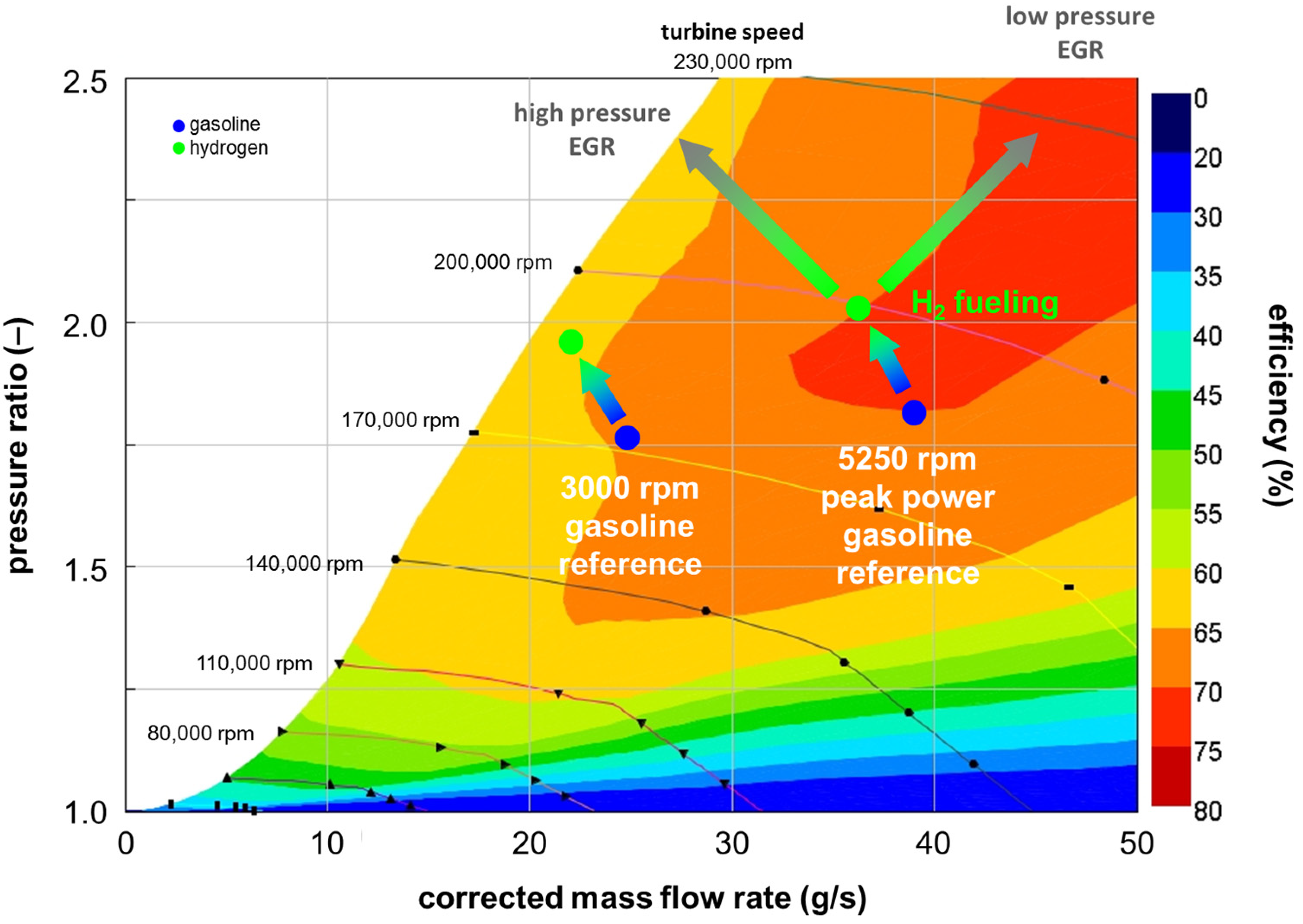
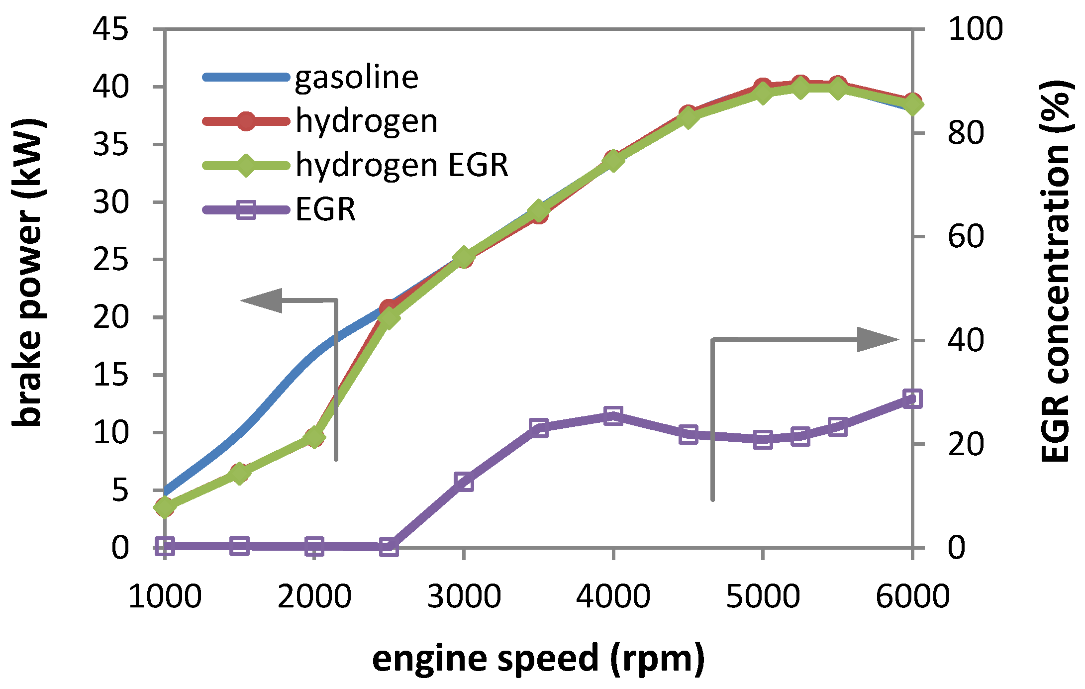
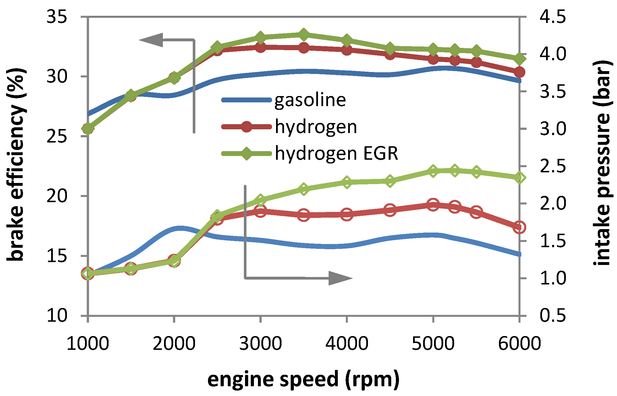
  • Full-load characteristics revealed that only the low-pressure recirculation configuration was favorable, as the high-pressure variant would move the compressor operating point close to the surge line even at peak power. Maximum recirculation levels were predicted to be close to 30%, but only at high rpm. Minor improvements in efficiency could be obtained with EGR, whereas the most consistent full-load relative gains of around 10% came from the fact that the engine was operated stoichiometrically compared to the AFRrel of 0.9 for gasoline. A major benefit was found in the form of contained maximum pressure rise rates, which were predicted to be below 10 bar/deg when using EGR and directly comparable to those calculated for the reference fuel.
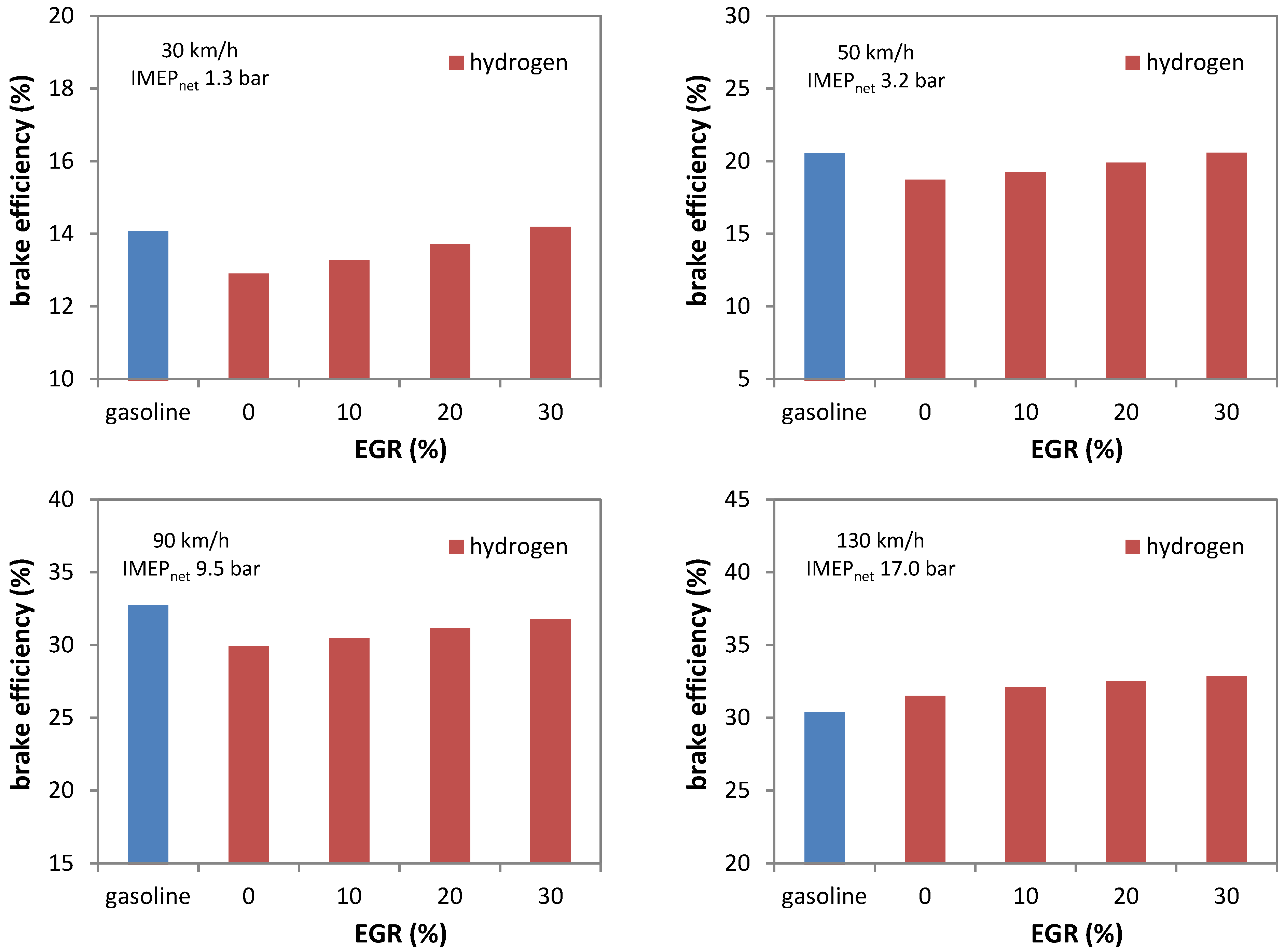
  • High heat losses were found to be a determining factor during urban driving. A positive aspect of EGR was that it could fully mitigate this negative effect at 30 and 50 km/h vehicle speed with recirculation rates of up to 30%; higher values would be required for the 90 km/h condition.
  • Highway driving at 130 km/h was found to be a condition that further emphasizes the potential of EGR when using H2, with an increase in efficiency of close to 8% compared to the gasoline reference case.

Author Contributions

Conceptualization, A.I., R.D.M. and V.Z.; methodology, A.I., B.M.V. and V.Z.; formal analysis, A.I.; data curation, A.I. and S.S.M.; writing—original draft preparation, A.I. and S.S.M.; writing—review and editing, A.I., R.D.M. and S.S.M.; supervision, B.M.V. All authors have read and agreed to the published version of the manuscript.

Funding

The authors from STEMS-CNR acknowledge the funding received within the SAYH2 PoC project financed by the European Union—NextGenerationEU (National Sustainable Mobility Center CN00000023, Italian Ministry of University and Research Decree n. 1033—17/06/2022, Spoke 12).

Data Availability Statement

Datasets generated as direct results of the simulations will be made available by the authors on request.

Conflicts of Interest

Author Vasco Zollo and Raffaele De Marinis were employed by the company Demax SRL. The remaining authors declare that the research was conducted in the absence of any commercial or financial relationships that could be construed as a potential conflict of interest.

Abbreviations

0D/1DZero-/one-dimensional
CFDComputational fluid dynamics
DEMDilution exponent multiplier
ECUElectronic control unit
EGRExhaust gas recirculation
GHGGreenhouse gas
HCCIHomogenous charge compression ignition
HPHigh pressure
ICEInternal combustion engine
LPLow pressure
MFBMass fraction burned
OEMOfficial equipment manufacturer
PFIPort fuel injection
PIDProportional integral derivative
PRRPressure rise rate
SISpark ignition
TDCTop dead center, with a for after and b for before

References

  1. Sacchi, R.; Bauer, C.; Cox, B.; Mutel, C. When, where and how can the electrification of passenger cars reduce greenhouse gas emissions? Renew. Sustain. Energy Rev. 2022, 162, 112475. [Google Scholar] [CrossRef]
  2. Le, T.T.; Sharma, P.; Bora, B.J.; Tran, V.D.; Truong, T.H.; Le, H.C.; Nguyen, P.Q.P. Fueling the future: A comprehensive review of hydrogen energy systems and their challenges. Int. J. Hydrog. Energ. 2024, 54, 791–816. [Google Scholar] [CrossRef]
  3. Rolo, I.; Costa, V.A.F.; Brito, F.P. Hydrogen-Based Energy Systems: Current Technology Development Status, Opportunities and Challenges. Energies 2024, 17, 180. [Google Scholar] [CrossRef]
  4. Mills, S.J. Heavy duty hydrogen ICE: Production realization by 2025 and system operation efficiency assessment. In Powertrain Systems for Net-Zero Transport, 1st ed.; CRC Press: Boca Raton, FL, USA, 2021; ISBN 9781003219217. [Google Scholar]
  5. Verhelst, S.; Wallner, T. Hydrogen-fueled internal combustion engines. Prog. Energ. Combust. Sci. 2009, 35, 490–527. [Google Scholar] [CrossRef]
  6. Molina, S.; Novella, R.; Gomez-Soriano, J.; Olcina-Girona, M. Experimental Activities on a Hydrogen-Fueled Spark-Ignition Engine for Light-Duty Applications. Appl. Sci. 2023, 13, 12055. [Google Scholar] [CrossRef]
  7. Kosmadakis, G.M.; Rakopoulos, D.C.; Rakopoulos, C.D. Assessing the cyclic-variability of spark-ignition engine running on methane-hydrogen blends with high hydrogen contents of up to 50%. Int. J. Hydrog. Energ. 2021, 46, 17955–17968. [Google Scholar] [CrossRef]
  8. Irimescu, A.; Cecere, G.; Sementa, P. Combustion Phasing Indicators for Optimized Spark Timing Settings for Methane-Hydrogen Powered Small Size Engines; SAE Technical Paper 2022-01-0603; SAE International: Warrendale, PA, USA, 2022. [Google Scholar] [CrossRef]
  9. Stępień, Z.A. Comprehensive Overview of Hydrogen-Fueled Internal Combustion Engines: Achievements and Future Challenges. Energies 2021, 14, 650. [Google Scholar] [CrossRef]
  10. Fischer, M.; Sterlepper, S.; Pischinger, S.; Seibel, J.; Kramer, U.; Lorenz, T. Operation principles for hydrogen spark ignited direct injection engines for passenger car applications. Int. J. Hydrog. Energ. 2021, 47, 5638–5649. [Google Scholar] [CrossRef]
  11. Gao, J.; Wang, X.; Song, P.; Tian, G.; Ma, C. Review of the backfire occurrences and control strategies for port hydrogen injection internal combustion engines. Fuel 2022, 307, 121553. [Google Scholar] [CrossRef]
  12. Yang, Z.; Zhang, F.; Wang, L.; Wang, K.; Zhang, D. Effects of injection mode on the mixture formation and combustion performance of the hydrogen internal combustion engine. Energy 2018, 147, 715–728. [Google Scholar] [CrossRef]
  13. Diéguez, P.M.; Urroz, J.C.; Sáinz, D.; Machin, J.; Arana, M.; Gandía, L.M. Characterization of combustion anomalies in a hydrogen-fueled 1.4 L commercial spark-ignition engine by means of in-cylinder pressure, block-engine vibration, and acoustic measurements. Energ. Convers. Manag. 2018, 172, 67–80. [Google Scholar] [CrossRef]
  14. Wallner, T.; Lohse-Busch, H.; Gurski, S.; Duoba, M.; Thiel, W.; Martin, D.; Korn, T. Fuel economy and emissions evaluation of BMW Hydrogen 7 Mono-Fuel demonstration vehicles. Int. J. Hydrog. Energ. 2008, 33, 7607–7618. [Google Scholar] [CrossRef]
  15. Verhelst, S.; Vancoillie, J.; Naganuma, K.; De Paepe, M.; Dierickx, J.; Huyghebaert, Y.; Wallner, T. Setting a best practice for determining the EGR rate in hydrogen internal combustion engines. Int. J. Hydrog. Energ. 2013, 38, 2490–2503. [Google Scholar] [CrossRef]
  16. Wang, S.; Zhai, Y.; Wang, Z.; Hou, R.; Zhang, T.; Ji, C. Comparison of air and EGR with different water fractions dilutions on the combustion of hydrogen-air mixtures. Fuel 2022, 324, 124686. [Google Scholar] [CrossRef]
  17. Kim, J.; Chun, K.M.; Song, S.; Baek, H.; Lee, S.W. The effects of hydrogen on the combustion, performance and emissions of a turbo gasoline direct-injection engine with exhaust gas recirculation. Int. J. Hydrog. Energ. 2017, 42, 25074–25087. [Google Scholar] [CrossRef]
  18. Yu, X.; Guo, Z.; He, L.; Dong, W.; Sun, P.; Du, Y.; Li, Z.; Yang, H.; Wang, S.; Wu, H. Experimental study on lean-burn characteristics of an SI engine with hydrogen/gasoline combined injection and EGR. Int. J. Hydrog. Energ. 2019, 44, 13988–13998. [Google Scholar] [CrossRef]
  19. Pukalskas, S.; Kriaučiūnas, D.; Rimkus, A.; Przybyła, G.; Droździel, P.; Barta, D. Effect of Hydrogen Addition on the Energetic and Ecologic Parameters of an SI Engine Fueled by Biogas. Appl. Sci. 2021, 11, 742. [Google Scholar] [CrossRef]
  20. Bao, L.; Sun, B.; Luo, Q. Optimal control strategy of the turbocharged direct-injection hydrogen engine to achieve near-zero emissions with large power and high brake thermal efficiency. Fuel 2022, 325, 124913. [Google Scholar] [CrossRef]
  21. Zhu, H.; Duan, J. Research on emission characteristics of hydrogen fuel internal combustion engine based on more detailed mechanism. Int. J. Hydrog. Energ. 2019, 44, 5592–5598. [Google Scholar] [CrossRef]
  22. Novella, R.; García, A.; Gomez-Soriano, J.; Fogué-Robles, A. Exploring dilution potential for full load operation of medium duty hydrogen engine for the transport sector. Appl. Energ. 2023, 349, 121635. [Google Scholar] [CrossRef]
  23. Sterlepper, S.; Fischer, M.; Claßen, J.; Huth, V.; Pischinger, S. Concepts for Hydrogen Internal Combustion Engines and Their Implications on the Exhaust Gas Aftertreatment System. Energies 2021, 14, 8166. [Google Scholar] [CrossRef]
  24. Guo, H.; Zhou, S.; Zou, J.; Shreka, M. A Numerical Investigation on De-NOx Technology and Abnormal Combustion Control for a Hydrogen Engine with EGR System. Processes 2020, 8, 1178. [Google Scholar] [CrossRef]
  25. Dhyani, V.; Subramanian, K.A. Control of backfire and NOx emission reduction in a hydrogen fueled multi-cylinder spark ignition engine using cooled EGR and water injection strategies. Int. J. Hydrog. Energ. 2019, 44, 6287–6298. [Google Scholar] [CrossRef]
  26. Meng, H.; Ji, C.; Shen, J.; Yang, J.; Xin, G.; Chang, K.; Wang, S. Analyzing the effects of cooled EGR on the knock of hydrogen-fueled Wankel rotary engine. Int. J. Hydrog. Energ. 2022, 47, 33094–33104. [Google Scholar] [CrossRef]
  27. Meng, H.; Ji, C.; Shen, J.; Yang, J.; Xin, G.; Chang, K.; Wang, S. Analysis of combustion characteristics under cooled EGR in the hydrogen-fueled Wankel rotary engine. Energy 2023, 263, 125815. [Google Scholar] [CrossRef]
  28. Irimescu, A.; Vaglieco, B.M.; Merola, S.S.; Zollo, V.; De Marinis, R. Conversion of a Small Size Passenger Car to Hydrogen Fueling: Focus on Rated Power and Injection Phasing Effects; SAE Technical Paper 2022-24-0031; SAE International: Warrendale, PA, USA, 2022. [Google Scholar] [CrossRef]
  29. Smart EQ ForTwo. Available online: www.smart.mercedes-benz.com (accessed on 15 August 2022).
  30. Irimescu, A.; Vaglieco, B.M.; Merola, S.S.; Zollo, V.; De Marinis, R. Conversion of a Small-Size Passenger Car to Hydrogen Fueling: Simulation of CCV and Evaluation of Cylinder Imbalance. Machines 2023, 11, 135. [Google Scholar] [CrossRef]
  31. Gamma Technologies. GT-SUITE Flow Theory Manual, Version 7.4; Gamma Technologies: Westmont, IL, USA, 2013. [Google Scholar]
  32. Cuturi, N.; Sciubba, E. Design of a Tandem Compressor for the Electrically-Driven Turbocharger of a Hybrid City Car. Energies 2021, 14, 2890. [Google Scholar] [CrossRef]
  33. Gerke, U.; Steurs, K.; Rebecchi, P.; Boulouchos, K. Derivation of burning velocities of premixed hydrogen/air flames at engine-relevant conditions using a single-cylinder compression machine with optical access. Int. J. Hydrog. Energ. 2010, 35, 2566–2577. [Google Scholar] [CrossRef]
  34. Rakopoulos, C.D.; Kosmadakis, G.M.; Demuynck, J.; De Paepe, M.; Verhelst, S. A combined experimental and numerical study of thermal processes, performance and nitric oxide emissions in a hydrogen-fueled spark-ignition engine. Int. J. Hydrog. Energ. 2011, 36, 5163–5180. [Google Scholar] [CrossRef]
  35. Verhelst, S.; Woolley, R.; Lawes, M.; Sierens, R. Laminar and Unstable Burning Velocities and Markstein Lengths of Hydro-gen-Air Mixtures at Engine-Like Conditions. Proc. Combust. Inst. 2005, 30, 209–216. [Google Scholar] [CrossRef]
  36. Kosmadakis, G.M.; Rakopoulos, C.D.; Demuynck, J.; De Paepe, M.; Verhelst, S. CFD modeling and experimental study of combustion and nitric oxide emissions in hydrogen-fueled spark-ignition engine operating in a very wide range of EGR rates. Int. J. Hydrog. Energ. 2012, 37, 10917–10934. [Google Scholar] [CrossRef]
  37. Hunicz, J.; Mikulski, M.; Geca, M.S.; Rybak, A. An applicable approach to mitigate pressure rise rate in an HCCI engine with negative valve overlap. Appl. Energ. 2019, 257, 114018. [Google Scholar] [CrossRef]
  38. Heywood, J.B. Internal Combustion Engine Fundamentals; McGraw Hill: New York, NY, USA, 1988; ISBN 9780070286375. [Google Scholar]
  39. Demuynck, J.; De Paepe, M.; Huisseune, H.; Sierens, R.; Vancoillie, J.; Verhelst, S. On the applicability of empirical heat transfer models for hydrogen combustion engines. Int. J. Hydrog. Energ. 2011, 36, 975–984. [Google Scholar] [CrossRef]
Figure 1. Illustration of the engine setup considered for simulation and the added EGR components in the LP configuration.
Applsci 14 00844 g001
Figure 2. Overview of the 0D/1D simulation model, with selected components highlighted and EGR routing.
Applsci 14 00844 g002
Figure 3. Compressor map used for the simulations and illustration of the operating points with gasoline (dark symbols) and H2 (light symbols) at 3000 rpm full load as well as peak power; the paths for achieving high- (long arrow pointing left) or low-pressure EGR (long arrow pointing right) are also highlighted.
Applsci 14 00844 g003
Figure 4. Full-load power curve with gasoline, hydrogen, and maximum achievable EGR.
Applsci 14 00844 g004
Figure 5. Full-load brake efficiency and absolute intake pressure.
Applsci 14 00844 g005
Figure 6. Full-load peak pressure and its maximum rise rate in cylinder #1.
Applsci 14 00844 g006
Figure 7. Brake efficiency at four different vehicle speed values and four levels of EGR for H2.
Applsci 14 00844 g007
Table 1. Engine specifications.
Displacement599 cm3
Number of cylinders3
Rated power40 kW @ 5250 rpm
Rated torque80 Nm @ 2000–4400 rpm
Bore × Stroke63.5 mm × 63.0 mm
Connecting rod length114 mm
Compression ratio9.5:1
Number of valves2 per cylinder
Intake valve opening/closure363/164 deg bTDC
Exhaust valve opening/closure157/349 deg a/bTDC
Fuel systemPort fuel injection at 3.5 bar for gasoline and 5 bar for gas H2
IgnitionInductive discharge, 2 spark plugs per cylinder
Disclaimer/Publisher’s Note: The statements, opinions and data contained in all publications are solely those of the individual author(s) and contributor(s) and not of MDPI and/or the editor(s). MDPI and/or the editor(s) disclaim responsibility for any injury to people or property resulting from any ideas, methods, instructions or products referred to in the content.

