Analysis of Lateral Forces for Assessment of Safety against Derailment of the Specialized Train Composition for the Transportation of Long Rails
Abstract
1. Introduction
- Reducing the share of road transport, with 50% of all medium-distance transport being carried out through rail and water transport;
- By 2030, 30% of freight transport over 300 km should be carried out through rail or water transport, and by 2050, over 50%;
- By 2050, most of the passenger transport over more than 300 km should be carried out through rail transport.
- The derailment phenomenon has a distinctly stochastic character. It depends on many factors, which at a certain moment in a complex combination can lead to its occurrence. Current research addresses the issue of derailment from the point of view of theory enrichment by accounting for one or more additional factors that could influence the occurrence of the adverse event. This effort to clarify the mechanism of the process is undeniably positive for two main reasons: first, although the wagons commissioned into operation meet the requirements of the regulatory documents, in practice, railway accidents caused by derailments often occur; and second, it could lead to an adjustment of national or international standards, which would reduce the likelihood of derailment.
- Although the proposed criteria are generally valid for the cases of examination of railway vehicles in a loaded or empty state, the safety assessment against derailment is carried out on an unloaded wagon. The reasons for this are logical—with a full wagon, the vertical force Q increases significantly (especially for freight wagons up to 3–4 times), while the lateral force Y increases less or in the same order under the influence of centrifugal forces.
- Currently, there are regulatory documents that, regardless of their shortcomings, should be respected to reduce the likelihood of derailment.
- In most analyzed publications and in all normative documents related to the derailment process, the evaluation is reduced to the application of Nadal’s criterion [21]. The limit value of the ratio (Y/Q) at a coefficient of friction equal to 0.36 was determined via Nadal’s criterion using Equation (1):
- Determination of the lateral forces acting on the central bearings of the bogies, obtained because of the elastic deformations of the long rails transported.
- Application of the method for theoretical assessment of safety against derailment, considering the permissible vertical load and the total values of lateral forces resulting from the movement of the train composition in a curved section of the track and from the elastic deformation of the transported rails.
- Development of a computational model for the research object;
- Numerical solution for determining the interaction forces between the deformed rails and the vertical columns of the wagon;
- Determination of the additional forces acting on the central bearings of the bogies.
2. Computational Model
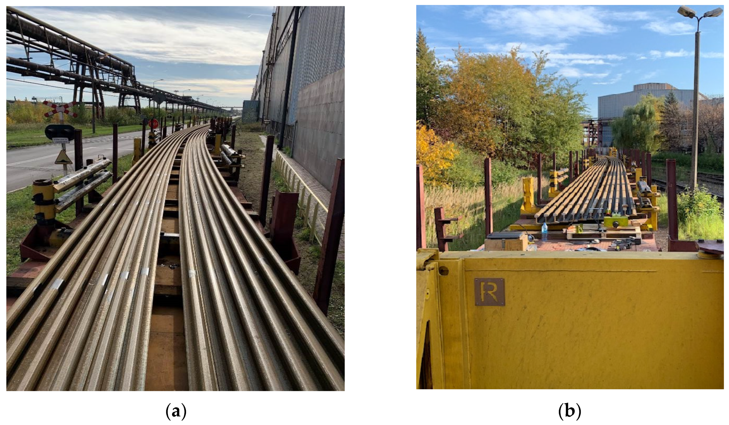
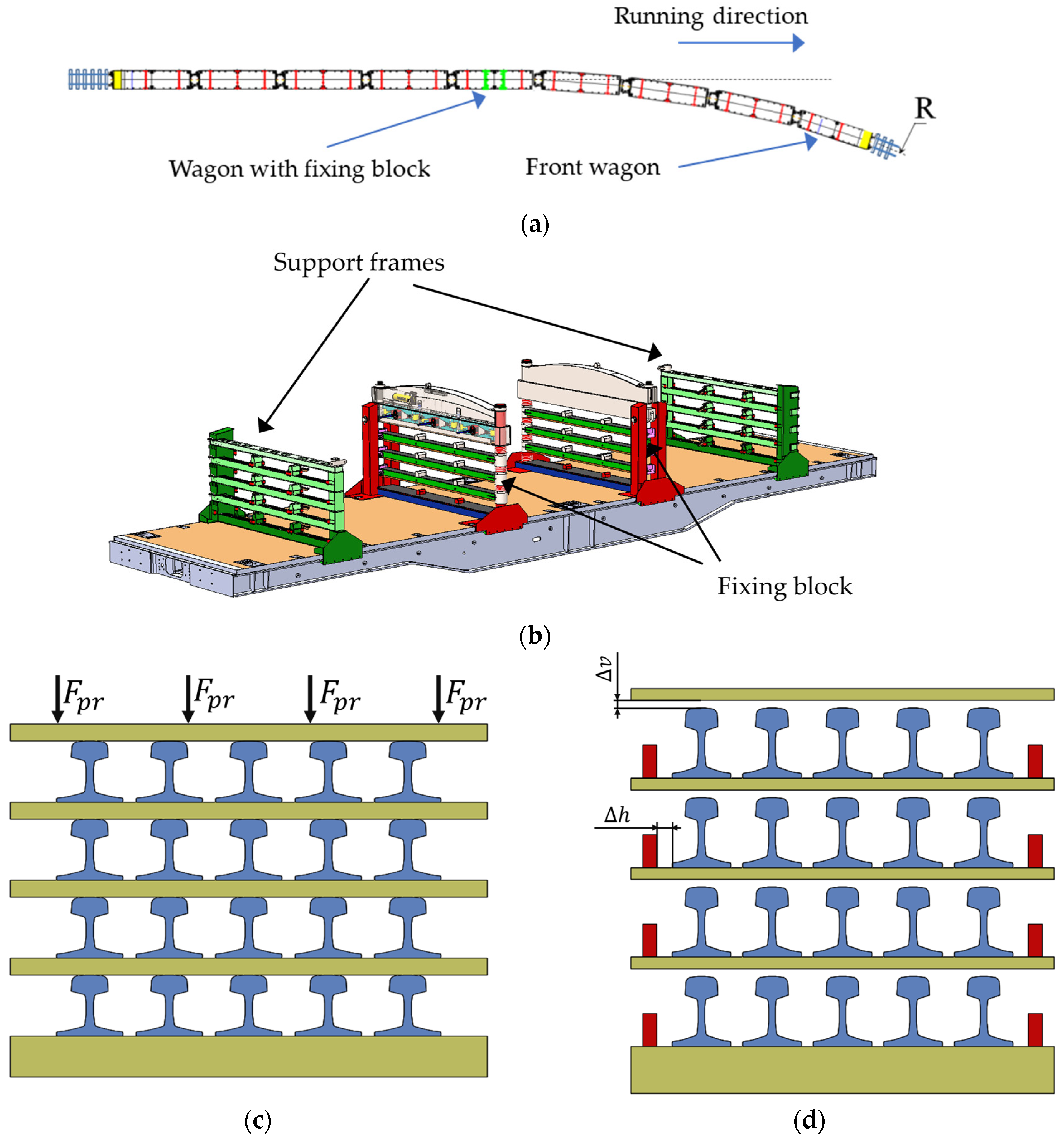
- The composition consists of nine wagons; the rails are located on support frames (Figure 2b) and are grouped in separate sections of five rails each.
- It is assumed that the first four wagons have entered the curve.
- The friction between the rails is neglected due to the peculiarities of the investigated structure.
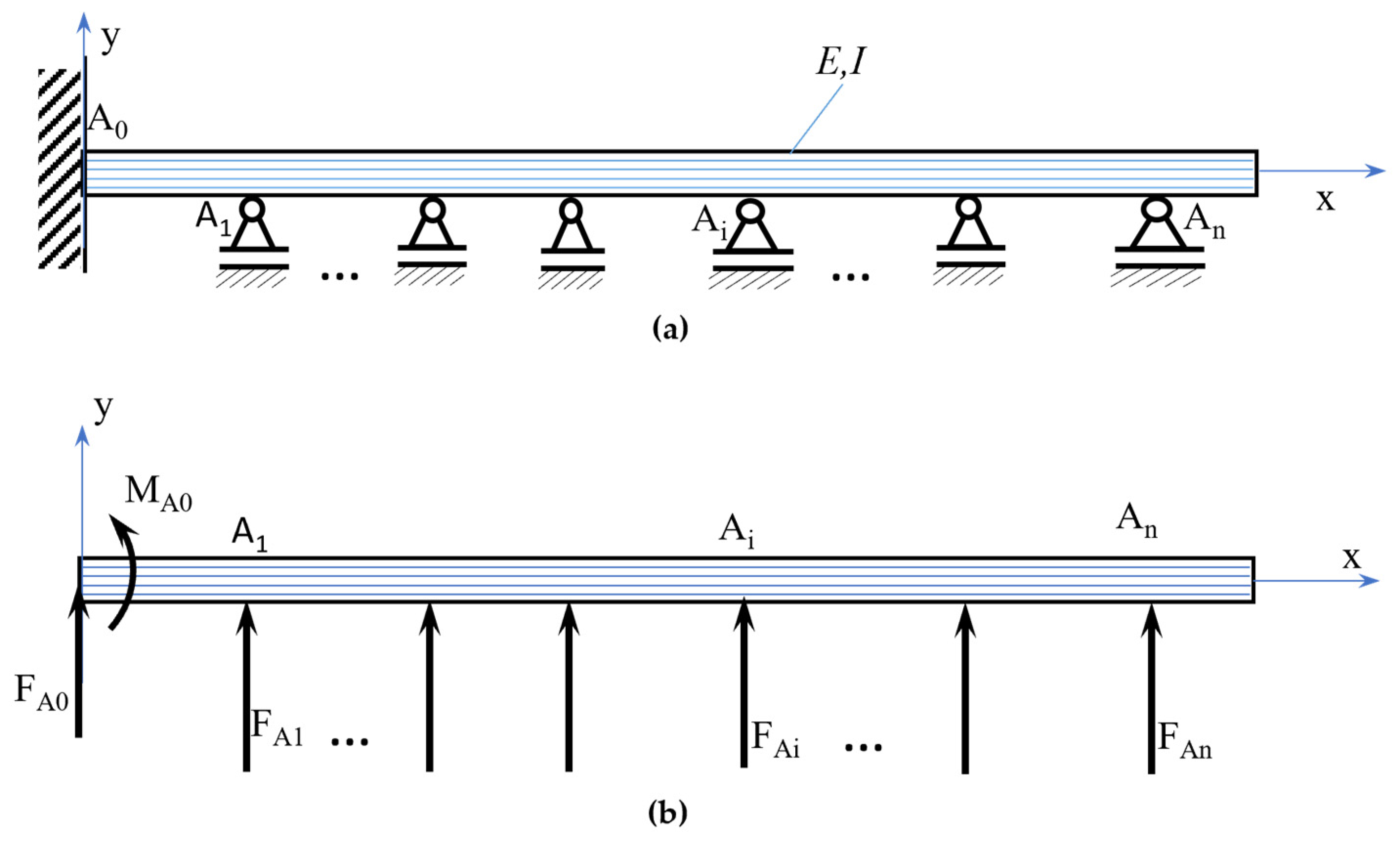
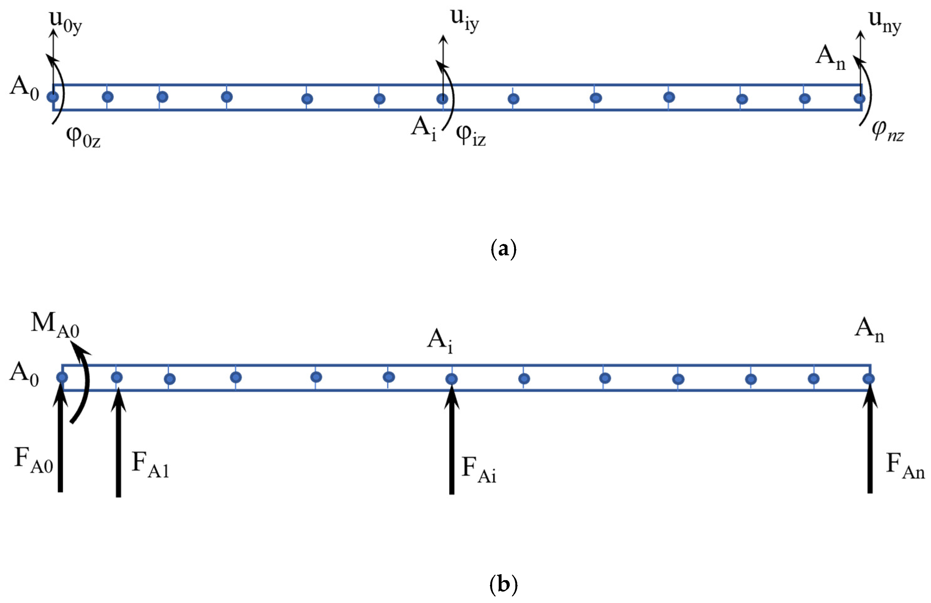
- In the wagon with the fixing blocks, it is assumed that the rails are immovably fixed, i.e., in the fixing block, it is assumed that we have a fixed beam (Figure 5a);
- At the locations of the supports Ai, it is assumed that unknown forces caused by the deformation of the beam act on the lateral direction (y axis) as shown in Figure 5b. The forces are directed perpendicular to the beam axis (x axis);
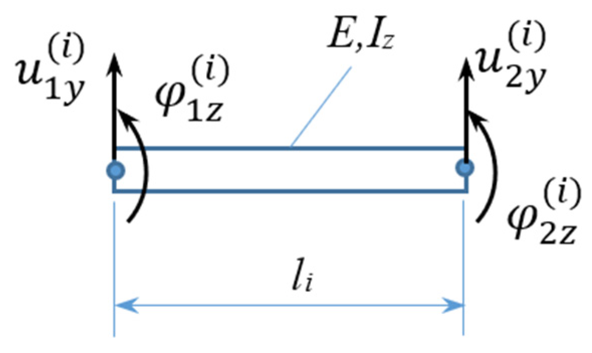
- Because of the large dimensions and deformations of the system and considering that the task is statically indeterminate, it is solved with a linear analysis method for the approximate determination of the forces in the supports. The obtained results contain some inaccuracies, which can be estimated by the studies presented in [25,27];
- When moving in a curve with radius R = 150 m, the speed of the train composition is small; therefore, the inertial forces are neglected.
3. Results from the Numerical Calculations
3.1. Results from Calculation of Lateral Forces between Rails and Vertical Columns of the Wagon
| Point | Coordinate x (m) | Coordinate y = uiy (m) | Reaction Identifier (Unit) | Value |
|---|---|---|---|---|
| A0 | 0 | 0 | MA0 (kN·m) | −20.9627 |
| A0 | 0 | 0 | FA0 (kN) | −20.9627 |
| A1 | 3.000 | 0 | FA1 (kN) | 15.4067 |
| A2 | 8.190 | −0.168 | FA2 (kN) | 28.7388 |
| A3 | 12.690 | −0.525 | FA3 (kN) | −45.0839 |
| A4 | 17.190 | −0.883 | FA4 (kN) | 22.1165 |
| A5 | 22.380 | −1.540 | FA5 (kN) | 21.0936 |
| A6 | 26.880 | −2.320 | FA6 (kN) | −42.6837 |
| A7 | 31.380 | −3.100 | FA7 (kN) | 21.6934 |
| A8 | 36.570 | −4.241 | FA8 (kN) | 20.7446 |
| A9 | 41.070 | −5.436 | FA9 (kN) | −43.0170 |
| A10 | 45.570 | −6.631 | FA10 (kN) | 25.6134 |
| A11 | 50.760 | −8.245 | FA11 (kN) | 4.9837 |
| A12 | 56.260 | −10.200 | FA12 (kN) | −8.6432 |
| Point | Coordinate x (m) | Coordinate y = uiy (m) | Reaction Identifier (Unit) | Value |
|---|---|---|---|---|
| A0 | 0 | 0 | MA0 (kN·m) | −21.8257 |
| A0 | 0 | 0 | FA0 (kN) | −21.8257 |
| A1 | 3.000 | 0 | FA1 (kN) | 22.8997 |
| A2 | 8.190 | −0.1436 | FA2 (kN) | −1.0583 |
| A3 | 12.690 | −0.4350 | FA3 (kN) | 1.3180 |
| A4 | 17.190 | −0.8733 | FA4 (kN) | −1.0934 |
| A5 | 22.380 | −1.5400 | FA5 (kN) | −1.1026 |
| A6 | 26.880 | −2.2530 | FA6 (kN) | 1.1627 |
| A7 | 31.380 | −3.1000 | FA7 (kN) | −0.0952 |
| A8 | 36.570 | −4.2410 | FA8 (kN) | −0.2744 |
| A9 | 41.070 | −5.3690 | FA9 (kN) | −0.4341 |
| A10 | 45.570 | −6.6274 | FA10 (kN) | 1.2717 |
| A11 | 50.760 | −8.2450 | FA11 (kN) | 4.8339 |
| A12 | 56.260 | −10.1100 | FA12 (kN) | −5.6022 |
3.2. Results from Calculation of Additional Lateral Forces in Wheel–Rail Contact
4. Assessment of Safety against Derailment
- The vertical load from the weight of 60 (4 rows × 15 rails per row) rails of type 60E1 with a length of 120 m (on the entire train composition) was applied;
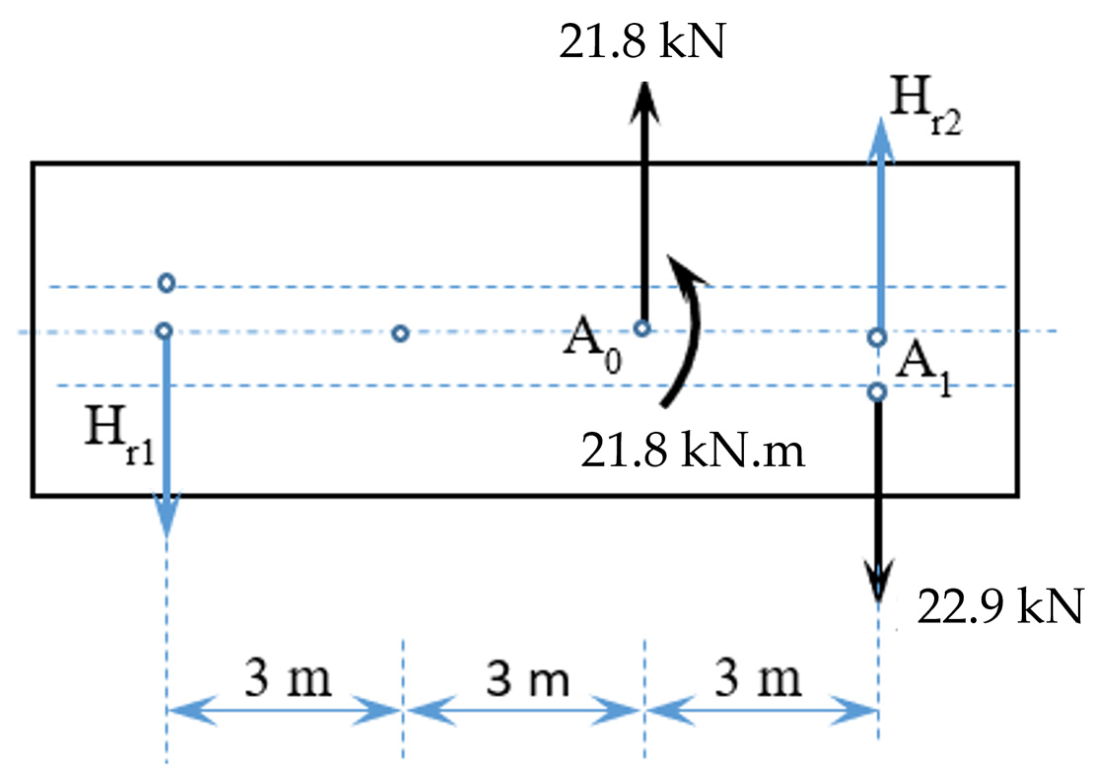
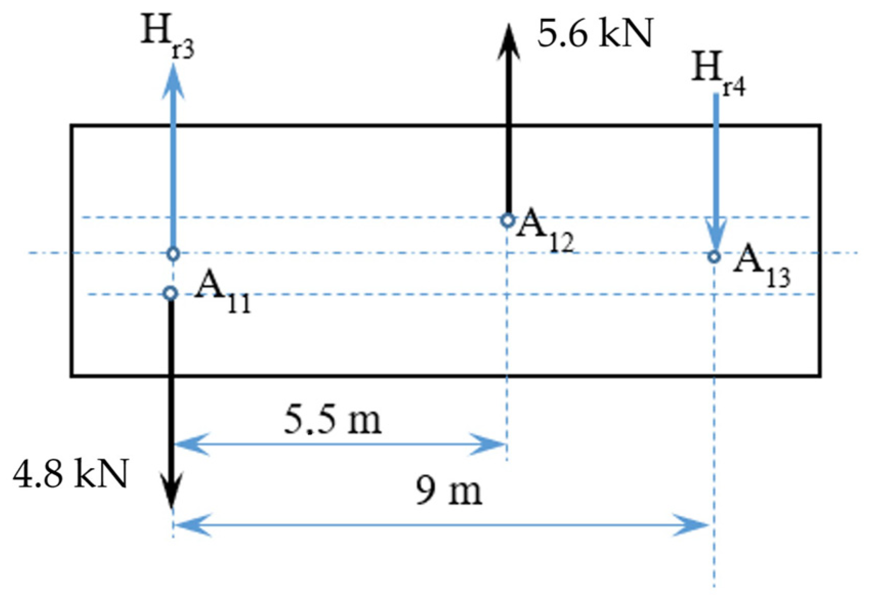
- The horizontal forces from Table 3 are applied in the central bearings of the wagon.
- The tare weight of each wagon is 21 tons;
- The distance between pivots is 9000 mm;
- The maximum load capacity is 69 tons;
- The maximum permissible load capacity when transporting rails is 0.8 × 69 tons = 49.6 tons according to [29];
- The wagon gauge is G1;
- The weight of two fixing blocks at the middle wagon is 2 × 2.5 tons = 5 tons;
- The weight of one support frame is 1 ton.
- The wagon equipped with fixing block to limit the longitudinal movements of the rails during transportation—the reason for this is that this is the wagon with the maximum tare weight (taking into account the weight of the installed frames) and in it, the lateral forces FA0 and FA1 (Table 2), respectively, and the lateral force Hri have a maximum values;
- Front wagon with protective walls. It has a reduced weight of the payload, which is placed asymmetrically on the wagon;
- Intermediate wagon (heaviest loaded wagon of all the wagons discussed above).
| Criterion | Wagon with Fixing Block | Front Wagon | Intermediate Wagon | Empty Wagon |
|---|---|---|---|---|
| 1.0698 | 0.8024 | 0.8295 | 0.8268 |
5. Conclusions
- Four different types of train composition wagons were considered: a wagon with fixing blocks, front wagon, intermediate wagon, and an empty wagon. The analysis of the results shows that the wagon with fixing blocks is most at risk of derailment. The obtained value (Table 4) fully corresponds to the requirements of the normative documents not only for real tests (<1.2), but also for theoretical studies (<1.08).
- The front and intermediate wagons have criterion values very close to that of the empty wagon. This shows that the emerging horizontal elastic forces do not significantly influence the derailment process.
- The developed model allows us to evaluate the influence of individual factors like pivot distance, own weight, number of rails, movement speed, overhang of the outer rail of the track, friction coefficient, etc., on the safety against derailment criterion.
- The transportation of long rails can be carried out with wagons that have different parameters (length, base, width, own weight, load capacity, etc.). After analyzing the mentioned parameters, the authors propose the most efficient version of the specialized train composition for 120 m long rails. When using another modification in the wagons or another rail length, the mentioned efficiency cannot be guaranteed.
- The obtained results show that the transportation of long rails with specialized train composition can be realized on four levels. This will significantly increase the efficiency of operators when delivering long new rails.
Author Contributions
Funding
Institutional Review Board Statement
Informed Consent Statement
Data Availability Statement
Acknowledgments
Conflicts of Interest
References
- An Official Website of the European Union. Roadmap to a Single European Transport Area: Towards a Competitive and Resource-Efficient Transport System. Available online: https://eur-lex.europa.eu/EN/legal-content/summary/roadmap-to-a-single-european-transport-area-towards-a-competitive-and-resource-efficient-transport-system.html (accessed on 24 November 2023).
- Jagadeep, B.; Kumar, P.-K.; Subbaiah, K.-V. Stress Analysis on Rail Wheel Contact. Int. J. Res. Eng. 2018, 1, 47–52. [Google Scholar]
- Bosso, N.; Magelli, M.; Zampieri, N. Simulation of wheel and rail profile wear: A review of numerical models. Rail. Eng. Sci. 2022, 30, 403–436. [Google Scholar] [CrossRef]
- Gao, Y.; Wang, P.; Wang, K.; Xu, J.; Dong, Z. Damage tolerance of fractured rails on continuous welded rail track for high-speed railways. Rail. Eng. Sci. 2021, 29, 59–73. [Google Scholar] [CrossRef]
- Milković, D.; Simić, G.; Radulović, S.; Lučanin, V.; Kostić, A. Experimental approach to assessment of safety against derailment of freight wagons. In Experimental Research and Numerical Simulation in Applied Sciences. CNNTech 2022; Lecture Notes in Networks and Systems, 564; Mitrovic, N., Mladenovic, G., Mitrovic, A., Eds.; Springer: Cham, Switzerland, 2023. [Google Scholar]
- Zeng, J.; Wu, P. Study on the wheel/rail interaction and derailment safety. Wear 2008, 265, 1452–1459. [Google Scholar] [CrossRef]
- Matsumoto, A.; Michitsuji, Y.; Ichiyanagi, Y.; Sato, Y.; Ohno, H.; Tanimoto, M.; Iwamoto, A.; Nakai, T. Safety measures against flange-climb derailment in sharp curve-considering friction coefficient between wheel and rail. Wear 2019, 432–433, 202931. [Google Scholar] [CrossRef]
- Lai, J.; Xu, J.; Liao, T.; Zheng, Z.; Chen, R.; Wang, P. Investigation on train dynamic derailment in railway turnouts caused by track failure. Eng. Fail. Anal. 2022, 134, 106050. [Google Scholar] [CrossRef]
- Yang, Z.; Li, Z. Wheel-rail dynamic interaction. In Woodhead Publishing Series in Civil and Structural Engineering—Rail Infrastructure Resilience; Calçada, R., Kaewunruen, S., Eds.; Woodhead Publishing: Cambridge, UK, 2022; pp. 111–135. ISBN 9780128210420. [Google Scholar] [CrossRef]
- Huang, J.-Y. Nadal’s Limit (L/V) to Wheel Climb and Two Derailment Modes. Eng. Phys. 2021, 5, 8–14. [Google Scholar] [CrossRef]
- Atmadzhova, D. Analysis of mathematical expressions for determine the criteria derailment of railway wheelset. Mech. Transp. Comm. 2011, 3, 42–49. [Google Scholar]
- Song, I.-H.; Koo, J.-S.; Shim, J.-S.; Bae, H.-U.; Lim, N.-H. Theoretical Prediction of Impact Force Acting on Derailment Containment Provisions (DCPs). Appl. Sci. 2023, 13, 3899. [Google Scholar] [CrossRef]
- Santamaria, J.; Vadillo, E.-G.; Gomez, J. Influence of creep forces on the risk of derailment of railway vehicles. Veh. Syst. Dyn. 2009, 47, 721–752. [Google Scholar] [CrossRef]
- Liu, X.; Saat, R.; Barkan, C. Analysis of Causes of Major Train Derailment and Their Effect on Accident Rates. Trans. Res. Rec. J. Trans. Res. Board. 2012, 2289, 154–163. [Google Scholar] [CrossRef]
- Ishida, M.; Ban, T.; Iida, K.; Ishida, H.; Aoki, F. Effect of moderating friction of wheel/rail interface on vehicle/track dynamic behaviour. Wear 2008, 265, 1497–1503. [Google Scholar] [CrossRef]
- Sala, A.J.; Felez, J.; de Dios Sanz, J.; Gonzalez, J. New Anti-Derailment System in Railway Crossings. Machines 2022, 10, 1224. [Google Scholar] [CrossRef]
- Anderson, R.-T.; Barkan, C.-P.-L. Derailment Probability Analyses and Modeling of Mainline Freight Trains. In Proceedings of the 8th International Heavy Haul Conference, Rio de Janeiro, Brazil, 14–16 June 2005; pp. 491–497. [Google Scholar]
- Diana, G.; Sabbioni, E.; Somaschini, C.; Tarsitano, D.; Cavicchi, P.; Di Mario, M.; Labbadia, L. Full-scale derailment tests on freight wagons. Veh. Syst. Dyn. 2021, 60, 1849–1866. [Google Scholar] [CrossRef]
- Kalivoda, J.; Neduzha, L. Simulation of Safety Against Derailment Tests of an Electric Locomotive. In Proceedings of 25th International Conference Engineering Mechanics, Svratka, Czech Republic, 13–16 May 2019; pp. 177–180. [Google Scholar]
- Ju, S.-H.; Ro, T.-I. Vibration and Derailment Analyses of Trains Moving on Curved and Can’t Rails. Appl. Sci. 2021, 11, 5106. [Google Scholar] [CrossRef]
- Wilson, N.; Fries, R.; Wittea, M.; Haigermoser, A.; Wrang, M.; Evans, J.; Orlova, A. Assessment of safety against derailment using simulations and vehicle acceptance tests: A worldwide comparison of state-of-the-art assessment methods. Veh. Syst. Dyn. 2011, 49, 1113–1157. [Google Scholar] [CrossRef]
- Wikaranadhi, P.; Handoko, Y.A. Curving Performance Analysis of a Freight Train Transporting 50-Meter-long Rail Using Multibody Dynamics Simulation. J. Eng. Tech. Sci. 2023, 55, 189–199. [Google Scholar] [CrossRef]
- Shvartsman, B.-S. Direct method for analysis of flexible cantilever beam subjected to two follower forces. Int. J. Non. Lin. Mech. 2009, 44, 249–252. [Google Scholar] [CrossRef]
- Ghuku, S.; Saha, K.-N. A theoretical and experimental study on geometric nonlinearity of initially curved cantilever beams. Eng. Sci. Tech. Int. J. 2016, 19, 135–146. [Google Scholar] [CrossRef]
- Beléndez, T.; Neipp, C.; Beléndez, A. Large and small deflections of a cantilever beam. Eur. J. Phys. 2002, 23, 371–379. [Google Scholar] [CrossRef]
- Kocatürk, T.; Akbaş, Ş.-D.; Şimşek, M. Large deflection static analysis of a cantilever beam subjected to a point load. Int. J. Eng. Appl. Sci. 2010, 2, 1–13. [Google Scholar]
- Wang, C.-M.; Lam, K.-Y.; He, X.-Q.; Chucheepsakul, S. Large deflections of an end supported beam subjected to a point load. Int. J. Non. Lin. Mech. 1997, 32, 63–72. [Google Scholar] [CrossRef]
- EN 14363:2019; Railway Applications—Testing and Simulation for the Acceptance of Running Characteristics of Railway Vehicles—Running Behaviour and Stationary Tests. European Committee for Standardization: Brussels, Belgium, 2019.
- Loading Guidelines. Code of Practice for the Loading and Securing of Goods on Railway Wagons, Goods, 7th ed.; International Union of Railways (UIC): Paris, France, 2023; Volume 2. [Google Scholar]
- EN 13674-1:2011; Railway Applications—Track—Rail—Part 1: Vignole Railway Rails 46 kg/m and Above. European Committee for Standardization: Brussels, Belgium, 2011.
- Specifications Of UIC 60 Steel Rail. Available online: https://www.railroadpart.com/news/specifications-of-uic-60-steel-rail.html (accessed on 16 November 2023).
- Merkel, M.; Öchsner, A. Eindimensionale Finite Elemente, 2nd ed.; Springer-Verlag: Berlin Heidelberg, Germany, 2015; pp. 79–83. [Google Scholar]
- Rao, S.-S. The Finite Element Method in Engineering, 5th ed.; Butterworth-Heinemann: Oxford, UK, 2011; pp. 311–354. [Google Scholar]
- Gardie, E.; Dubale, H.; Tefera, E.; Bezzie, Y.-M.; Amsalu, C. Numerical analysis of rail joint in a vertical applied load and determining the possible location of joints. Forc. Mech. 2022, 6, 100064. [Google Scholar] [CrossRef]
- Kukulski, J.; Jacyna, M.; Gołębiowski, P. Finite Element Method in Assessing Strength Properties of a Railway Surface and Its Elements. Symmetry 2019, 11, 1014. [Google Scholar] [CrossRef]
- Stoilov, V.; Slavchev, S.; Maznichki, V.; Purgic, S. Method for Theoretical Assessment of Safety against Derailment of New Freight Wagons. Appl. Sci. 2023, 13, 12698. [Google Scholar] [CrossRef]



| Wagon with Fixing Block | Front Wagon | Unit | Value |
|---|---|---|---|
| Hr1 | - | (kN) | 4.84 |
| Hr2 | - | (kN) | 5.94 |
| - | Hr3 | (kN) | 2.62 |
| - | Hr4 | (kN) | 3.42 |
| Parameter Description | Symbol/Equation | Value |
|---|---|---|
| Total reaction force of the attacking wheel of wheelset 1 | Y1a 1 | 122.814 kN |
| Total reaction force of the non-attacking wheel of wheelset 1 | Y1i 1 | −70.732 kN |
| Minimum deflection of the bogie frame to be reached during tests of the wagon [28] | 0.0076 m | |
| Twist of the bogie frame during test (2a+ is distance between wheelsets) [28] | 4.2222‰ | |
| Minimum deflection of the wagon frame to be reached during tests of the wagon [28] | 33.2 mm | |
| Twist of the wagon frame during test (2a is the pivot distance) [28] | 3.6483‰ | |
| Load force during torsion test | 10 kN | |
| Deflection of the wagon frame under ΔFp | 88.22 mm | |
| Force needed to achieve Δz* | 3.763 kN | |
| Maximum force additionally loading bogie frame under ΔFz* | 3.481 kN | |
| Minimum force additionally loading bogie frame under ΔFz* | 0.282 kN | |
| Maximum force overloading first wheel | 1.7405 kN | |
| Minimum force overloading first wheel | 0.141 kN | |
| Additional maximum vertical reaction force in wheels (Equation (25) of [36]) | 2.007 kN | |
| Additional minimum vertical reaction force in wheels (Equation (25) of [36]) | −0.125 kN | |
| Nominal vertical force loading the wheels | 93.401 kN | |
| Minimum vertical wheel reaction force | 93.276 kN | |
| Minimum vertical wheel reaction force | 95.408 kN |
Disclaimer/Publisher’s Note: The statements, opinions and data contained in all publications are solely those of the individual author(s) and contributor(s) and not of MDPI and/or the editor(s). MDPI and/or the editor(s) disclaim responsibility for any injury to people or property resulting from any ideas, methods, instructions or products referred to in the content. |
© 2024 by the authors. Licensee MDPI, Basel, Switzerland. This article is an open access article distributed under the terms and conditions of the Creative Commons Attribution (CC BY) license (https://creativecommons.org/licenses/by/4.0/).
Share and Cite
Stoilov, V.; Sinapov, P.; Slavchev, S.; Maznichki, V.; Purgic, S. Analysis of Lateral Forces for Assessment of Safety against Derailment of the Specialized Train Composition for the Transportation of Long Rails. Appl. Sci. 2024, 14, 860. https://doi.org/10.3390/app14020860
Stoilov V, Sinapov P, Slavchev S, Maznichki V, Purgic S. Analysis of Lateral Forces for Assessment of Safety against Derailment of the Specialized Train Composition for the Transportation of Long Rails. Applied Sciences. 2024; 14(2):860. https://doi.org/10.3390/app14020860
Chicago/Turabian StyleStoilov, Valeri, Petko Sinapov, Svetoslav Slavchev, Vladislav Maznichki, and Sanel Purgic. 2024. "Analysis of Lateral Forces for Assessment of Safety against Derailment of the Specialized Train Composition for the Transportation of Long Rails" Applied Sciences 14, no. 2: 860. https://doi.org/10.3390/app14020860
APA StyleStoilov, V., Sinapov, P., Slavchev, S., Maznichki, V., & Purgic, S. (2024). Analysis of Lateral Forces for Assessment of Safety against Derailment of the Specialized Train Composition for the Transportation of Long Rails. Applied Sciences, 14(2), 860. https://doi.org/10.3390/app14020860


