Abstract
The primary focus of this paper is to investigate the application of ANSYS Workbench 19.2 software’s advanced feature, known as Separating Morphing and Adaptive Remeshing Technology (SMART), in simulating the growth of cracks within structures that incorporate holes. Holes are strategically utilized as crack arrestors in engineering structures to prevent catastrophic failures. This technique redistributes stress concentrations and alters crack propagation paths, enhancing structural integrity and preventing crack propagation. This paper explores the concept of using holes as crack arrestors, highlighting their significance in increasing structural resilience and mitigating the risks associated with crack propagation. The crack growth path is estimated by applying the maximum circumferential stress criterion, while the calculation of the associated stress intensity factors is performed by applying the interaction integral technique. To analyze the impact of holes on the crack growth path and evaluate their effectiveness as crack arrestors, additional specimens with identical external dimensions but without any internal holes were tested. This comparison was conducted to provide a basis for assessing the role of holes in altering crack propagation behavior and their potential as effective crack arrestors. The results of this study demonstrated that the presence of a hole had a significant influence on the crack growth behavior. The crack was observed to be attracted towards the hole, leading to a deviation in its trajectory either towards the hole or deflecting around it. Conversely, in the absence of a hole, the crack propagated without any alteration in its path. To validate these findings, the computed crack growth paths and associated stress intensity factors were compared with experimental and numerical data available in the open literature. The remarkable consistency between the computational study results for crack growth path, stress intensity factors, and von Mises stress distribution, and the corresponding experimental and numerical data, is a testament to the accuracy and reliability of the computational simulations.
1. Introduction
The study of crack propagation and its mitigation is of paramount importance in engineering applications to ensure the structural integrity and safety of various components [1]. Understanding the behavior of cracks, their growth patterns, and the factors influencing their propagation is crucial in designing reliable and durable structures. Crack propagation is a complex phenomenon influenced by various factors such as loading conditions, material properties, and geometric constraints [2]. Holes, strategically placed in structures, have been recognized as effective crack arrestors. The presence of holes alters stress distribution, redistributes stress concentrations, and changes the crack propagation path. This phenomenon has been extensively studied to understand the mechanisms of crack arrest and develop design guidelines for incorporating holes as crack arrestors [3,4]. One key aspect of crack growth analysis is the calculation of stress intensity factors (SIFs). SIFs are fundamental parameters that govern crack propagation behavior and can be determined using analytical, numerical, or experimental methods [5,6]. In practice, computational methods are widely utilized to evaluate the durability of components with pre-existing cracks, focusing on their ultimate load capacity and crack progression. However, the unpredictable nature of crack paths necessitates the use of appropriate computational methodologies that can accurately consider the instability mechanisms inherent in the computation. Over the years, advanced computational tools and numerical methods have played a pivotal role in simulating and analyzing crack growth behavior. In recent years, the finite element method (FEM) has become increasingly prominent as an effective numerical approach for modeling and analyzing the growth of cracks. This method involves dividing the structure into smaller elements and solving the governing equations, enabling a comprehensive investigation of stress distribution, deformation, and the behavior of crack propagation [7,8,9,10]. In some cases, the geometry of the hole can be optimized to induce crack arrest. By designing the hole with specific dimensions, such as size, shape, and orientation, the crack can be forced to terminate, preventing further propagation. The hole acts as a barrier that prevents the crack from extending beyond a certain point, effectively arresting its growth and avoiding catastrophic failure. Holes are used as crack arrestors in various engineering structures. Examples include aircraft structures, pressure vessels, power transmission structures, bridge components, and high-stress machine components. The ANSYS Workbench provides advanced capabilities to simulate crack growth in structures with holes, allowing for an in-depth analysis of crack behavior and the evaluation of hole effectiveness as crack arrestors. The ANSYS Workbench employs various crack growth criteria, such as stress intensity factors (SIFs), energy release rate, or crack tip opening displacement (CTOD), to determine crack growth initiation and propagation. The assessment of crack initiation in the ANSYS Smart Crack Growth module involves the utilization of a range of criteria. These criteria encompass stress-based, strain-based, energy-based, fracture mechanics, and damage-based approaches. Stress-based criteria scrutinize stress levels, strain-based criteria focus on strain levels, energy-based criteria analyze energy release rates, fracture mechanics criteria apply principles from linear elastic fracture mechanics, and damage-based criteria monitor the accumulation of material damage. Crack initiation is predicted when the predefined thresholds for each criterion are surpassed. These criteria are implemented within the software’s algorithms to evaluate the critical conditions for crack growth and predict crack propagation paths. Additionally, the ANSYS Workbench offers capabilities for adaptive meshing, which allows for automatic refinement of the mesh around the crack tip to accurately capture stress gradients and accurately predict crack growth. Furthermore, software packages like Abaqus [11,12], COMSOL [13,14], FRANC3D [15,16], Zencrack [17], AFGROW [18], NASGRO [19], and Nastran [17] also provide powerful computational tools for simulating crack growth and analyzing the behavior of structures subjected to crack propagation. Additionally, there exist various software options for simulating crack propagation, such as the advanced iterative–finite element method (AI-FEM) [20] and advanced finite element analysis (AFEA) [21]. Meanwhile, there has been a rapid development of new approaches and methods in various fields of study. These include the discrete element method [22,23,24], element-free Galerkin method [25], extended finite element method [26,27], cohesive element method [28,29], boundary element method (BEM) [30,31,32], and phase-field method [33].
In a study by [34], displacement fields were experimentally measured to validate numerical simulations in a modified compact tension specimen. The specimen contained a machined hole positioned ahead of the crack propagation, causing a diversion of the crack path due to the modified stress field induced by the stress concentration factor. The effect of the drilled hole on the crack growth path was explained, as the presence of the hole resulted in a curved crack propagation path, inducing a mixed-mode (I/II) loading condition. In a numerical study conducted by Chatzigeorgiou [35], various geometries with holes were tested to investigate their impact on crack propagation and the potential for crack arrest. The results of this study are conceptually different from previously published ones [36,37,38,39] as they specifically address a part of the research gap related to the behavior of cracks in the presence of multiple holes and their influence on crack propagation. By focusing on multiple holes and their specific configurations, this study provides novel insights that were not previously explored in the published research. Additionally, the study highlights how the presence of holes affects stress distribution, particularly von Mises stress, and emphasizes how these holes contribute to stress redistribution, ultimately enhancing structural integrity by mitigating stress concentrations.
The limited understanding of crack growth in the presence of holes as crack arrestors constitutes a significant research gap. Further investigation is needed to explore several specific areas, including the impact of hole size, shape, and orientation on crack behavior, the interaction between material properties and the presence of holes, the behavior of multiple-hole configurations, the effects of dynamic loading conditions on crack arrest, and the optimization of hole configurations to enhance crack arrest effectiveness. Closing these research gaps will contribute to advancing our knowledge in this area and facilitate the development of improved design strategies for enhancing structural integrity and safety. This study aimed to address a part of the research gap by investigating the impact of multiple holes and their positions relative to the initial crack tip, along with the initial crack length. The objective was to gain insights into the behavior of cracks in the presence of multiple holes and their influence on crack propagation. By considering these factors, this study aimed to contribute to a better understanding of crack growth dynamics and further advance the knowledge in this field.
2. Materials and Methods
Separating, Morphing, Adaptive, and Remeshing Technology (SMART) focuses on enhancing crack growth simulations by utilizing advanced meshing and adaptive techniques. This feature aims to provide accurate and efficient representations of crack propagation in the ANSYS Workbench. The SMART crack growth feature incorporates the following components:
- Separating which has the capability ensures that the mesh accurately captures the behavior of cracks and contact interfaces. It allows for the representation of gaps and separation occurring at crack interfaces or contact regions. This enables the more realistic modeling of crack propagation and contact behavior.
- Morphing which is a key aspect of SMART technology that enables the mesh to adapt and deform to changes in crack geometry. As cracks propagate or deformations occur, the mesh is dynamically adjusted to maintain accurate representation. This ensures that the mesh aligns with the evolving crack shape throughout the simulation.
- Adaptive: The adaptive component of SMART technology focuses on refining the mesh in areas of interest, such as near crack tips or regions experiencing high stress gradients. By adapting the mesh locally, it ensures that the critical details of crack growth are accurately captured while optimizing computational efficiency. Adaptive meshing helps to maintain an optimal balance between accuracy and computational cost.
- Remeshing, which is the process of regenerating the mesh based on predefined criteria or significant changes in crack geometry or deformation. When cracks propagate, large deformations occur, or other significant changes take place, and the mesh is updated to accurately represent the evolving crack geometry. Remeshing ensures that the simulation continues with an appropriate mesh that captures the changing crack behavior.
The present study used the maximum circumferential stress criterion, which is one of the criteria incorporated in ANSYS for evaluating crack growth under mixed-mode loading conditions. This criterion operates on the assumption that crack propagation predominantly occurs in the direction of maximum circumferential stress. The direction of crack growth is determined by evaluating the direction of maximum circumferential stress, which is perpendicular to the direction of the total stress-intensity factor. The crack propagation direction in this criterion is determined using the following formula [40,41]:
where θ is the angle of crack growth and KI and KII correspond to the first and second mode of the stress intensity factor, respectively.
In the context of static crack growth simulation, ANSYS Mechanical offers two commonly used fracture criteria: the J-integral and stress intensity factor. In this particular study, the stress intensity factor criterion was employed. According to this criterion, crack propagation occurs when the stress intensity factor (KI) surpasses the fracture toughness of the material. By using pre-meshed crack modeling and incorporating contact elements, ANSYS Smart Crack Growth can accurately simulate the contact between crack faces and model the crack propagation process.
3. Results and Discussions
3.1. Three-Point Bending of a Beam with Three Circular Holes
This case study seeks to verify the capability and accuracy of the ANSYS Smart Crack Growth feature in assessing crack propagation paths under mixed-mode loading conditions. To accomplish the validation, the process entails utilizing three-point bending beams with varying initial crack lengths and locations. The beam configurations displayed in Figure 1 and Figure 2 represent two distinct scenarios: one without any holes and the other with three holes. These configurations are specifically designed to analyze and evaluate the crack behavior exhibited under different conditions. Table 1 presents a comprehensive overview of the material properties associated with the three-point bending beam utilized in this study. The material is characterized by linear elastic properties, which means that it exhibits a linear relationship between stress and strain within its elastic range. In several studies [42,43,44], there appears to be an inconsistency in referring to the beam as polymethyl methacrylate (PMMA) despite the use of different materials. It is important to note that this misnomer should be corrected to accurately reflect the material actually utilized in each study. The initial experimental work conducted by Bittencourt et al. [45] on PMMA specimens, which exhibited a linear elastic behavior, served as the basis for naming the beam as PMMA. However, it should be acknowledged that the authors of these studies expanded their investigations to include other linear elastic materials alongside PMMA. Therefore, the beam material designation should be adjusted to align with the specific material used in each study. To confirm the accuracy of the simulated crack paths, experimental results from Bittencourt et al. [45] are employed as a point of comparison. The specimens in this study are subjected to constraints that restrict all degrees of freedom, beginning from the location of the left pin. However, the right pin is permitted to move solely in one direction along the X axis.
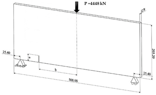
Figure 1.
Geometrical representation of the three-point bending beam without holes (dimensions in mm).
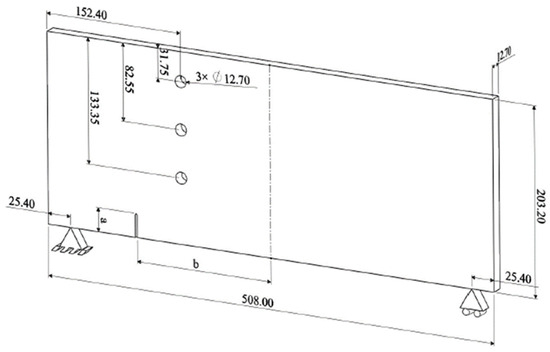
Figure 2.
Geometrical representation of the three-point bending beam with three circular holes (dimensions in mm).

Table 1.
Mechanical characteristics of cold-rolled SAE 1020 steel [43].
The geometry under consideration has specific dimensions: a length of 2 L = 508 mm, a width of 203.2 mm, and a thickness of 12.7 mm. All specimens share the same dimensions, hole positions, and hole sizes. However, primary variations occur in the initial crack length and its positions, as specified in Table 2. The specimens are subjected to a point load of 4448 kN, which is applied at the midpoint of the top section. Meanwhile, the bottom section of the specimens features two simply supported points, with one point fixed and the other point movable in the x-direction. This configuration allows for controlled loading conditions and facilitates the examination of the specimens’ mechanical response under specific loading scenarios. Figure 3 displays the initial finite element meshes for specimens 1 and 2. In specimen 1, there are 253,462 nodes and 155,476 elements, while in specimen 2, there are 269,563 nodes and 165,231 elements.
Table 2.
Simulated three-point bending beam configurations.
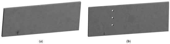
Figure 3.
Finite element meshes for the three-point bending beam (a) without hole and (b) with three holes.
3.1.1. Case I
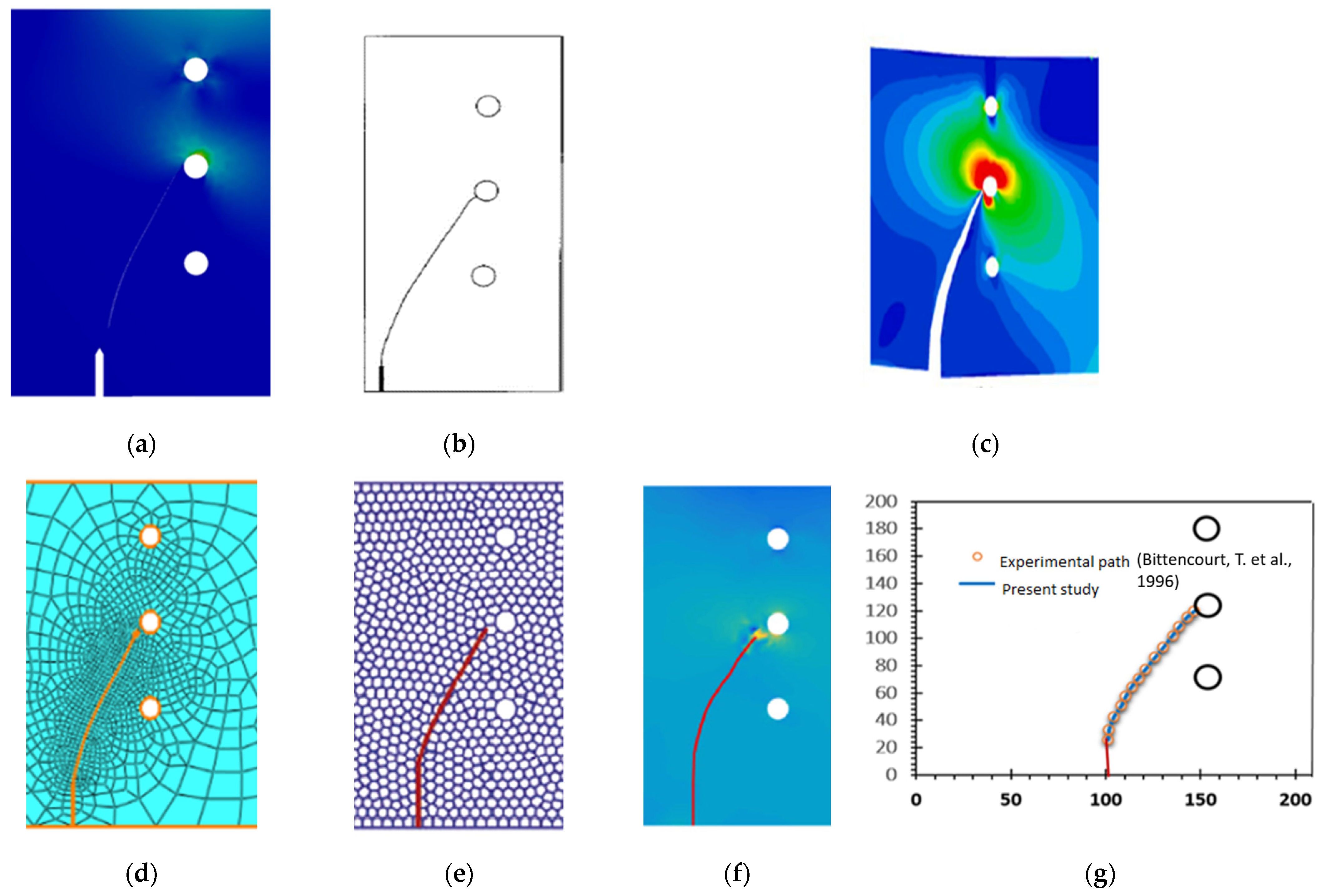
In this particular specimen, the initial crack length was set to 38.1 mm, and its position was located 127 mm away from the mid-span of the specimen. These specific values were chosen to investigate the crack behavior under the given conditions and assess the influence of the crack’s initial length and position on the interaction with the middle hole. It is clearly observable that the crack is noticeably attracted towards the middle hole, indicating a strong tendency to move towards it. As the crack continues to propagate, it ultimately reaches the left side of the middle hole, leading to a complete cessation of crack growth. Figure 4 illustrates the direction of crack growth for case I. Subsequently, the direction of crack growth observed in this study is compared with both experimental crack trajectories conducted by Bittencourt et al. [45], and numerical results obtained by Andrade and Leonel [46], who utilized an adaptive finite element approach on a multifunctional super singular element. Additionally, a comparison is made with the numerical method using the floating node method, which was combined with the symplectic analytical singular element by Fu et al. [47]. The crack growth path predicted in the current study demonstrated greater accuracy in reaching the middle hole compared to the predicted crack path obtained by Huynh et al. [48], which employed a polygonal XFEM with new numerical integration. Furthermore, the results obtained using a coupled extended meshfree–smoothed meshfree method by Ma et al. [49] were also used for comparison.

Figure 4.
Crack growth path for case 1, (a) present study, (b) experimental [45], (c) numerical [46], (d) numerical [47], (e) numerical [48], (f) numerical [49], and (g) coordinates of crack growth path.
To enhance the visualization of the accuracy of the predicted crack growth path in comparison to the experimental path obtained by Bittencourt et al. [45], Figure 4g displays the crack tip coordinate throughout the crack growth process, which closely aligns with the experimental data. This similarity between the predicted and experimental crack tip coordinates highlights the effectiveness and reliability of the crack growth prediction in the analysis.
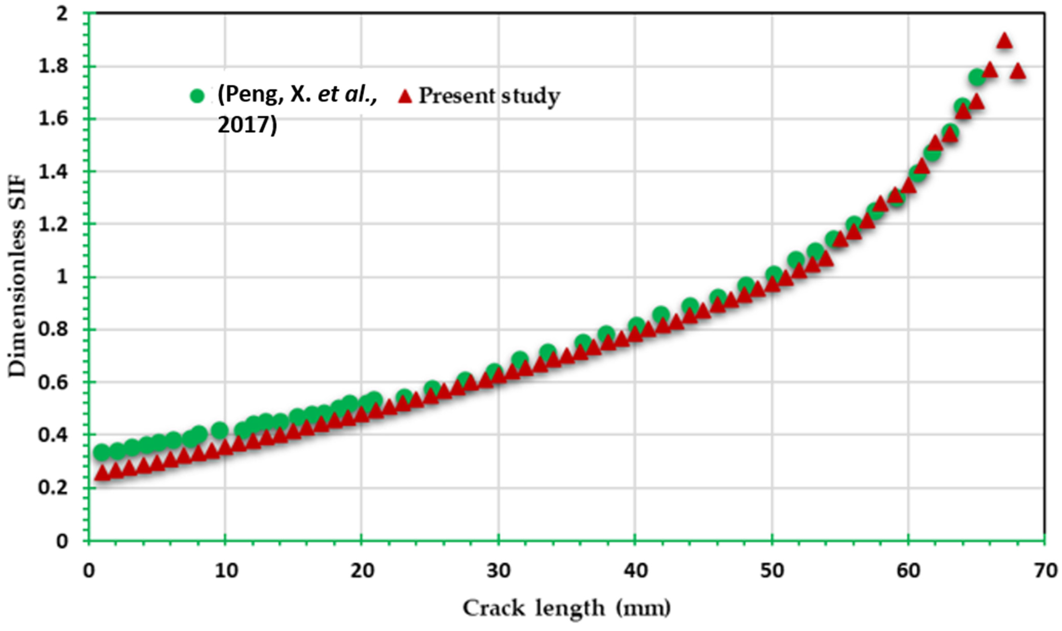
In order to assess the dimensionless SIF (), a comparative analysis was conducted between the results obtained in this study and the results obtained by Peng et al. [50]. Peng et al. [50] utilized XFEM and a smooth nodal stress method for their investigation. The comparison, as shown in Figure 5, demonstrates a high degree of similarity between the present study and theirs.
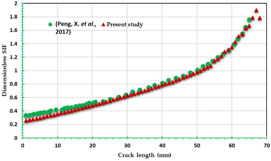
Figure 5.
Comparative results for dimensionless SIF of case I [50].
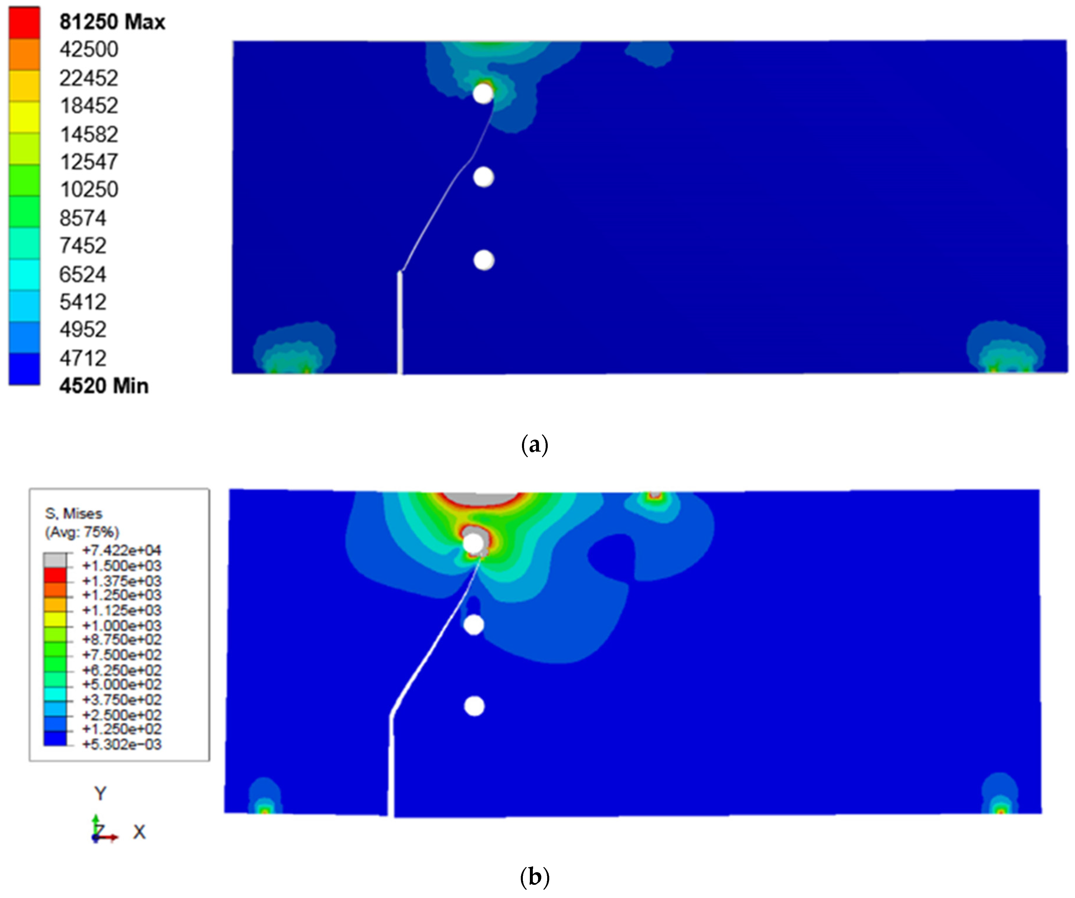
Figure 6 shows a comprehensive comparison of the von Mises stress distribution results for case I in the present study with the corresponding findings obtained by Dirik and Yalçinkaya [43] using a mesh-independent computational algorithm that was specifically developed and integrated into the widely used commercial finite element software ABAQUS. The figure provides a visual representation of the stress distribution patterns and highlights the agreement between the two studies. Notably, there is an excellent level of concordance observed in both the stress distribution and the stress values.
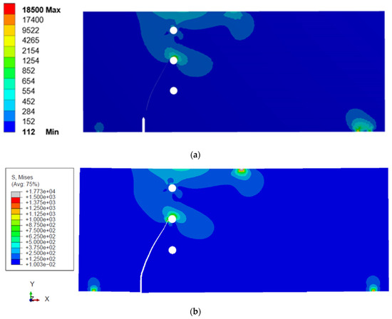
Figure 6.
Von Mises stress distribution for case I: (a) present study; (b) ABAQUS with a mesh-independent computational algorithm [43].
Figure 7 shows the crack growth path predicted by ABAQUS standard software without a mesh-independent computational algorithm, as reported by Dirik and Yalçinkaya [43]. Notably, no modifications or enhancements were made to the software for this analysis. However, in this specific instance, the predicted crack path intersects the bottom hole, in contrast to the expected behavior observed in the experimental results where the crack is anticipated to pass the hole and reach the middle hole. This discrepancy between the predicted and experimental crack growth paths highlights a divergence between the simulation and real-world observations. It suggests the need for further investigation and potential improvements in the modeling techniques employed within the ABAQUS software. It is important to note that in contrast to ABAQUS, the SMART crack growth method employed in ANSYS has the capability to precisely predict crack paths without requiring user interaction or programming interference. This feature of ANSYS offers the potential advantage of accurate crack path prediction, providing a notable distinction between the two software tools. Furthermore, the study conducted by Dirik and Yalçinkaya [43] involved manually adjusting the crack growth increment, resulting in variations in the crack growth path, whereas ANSYS employs an automated selection mechanism that determines the crack growth increment based on the nature of the loading, distinguishing between pure mode I or mixed-mode loading conditions. This disparity in methodologies highlights the distinction between Dirik and Yalçinkaya’s approach, which required manual intervention for adjusting the crack growth increment, and ANSYS, which automates this process, ensuring the selection of the appropriate crack growth path based on the specific loading conditions. As a result, ANSYS offers a more streamlined and reliable method for accurately determining the crack growth path.

Figure 7.
Predicted crack growth path using ABAQUS without a mesh-independent computational algorithm [43].
3.1.2. Case II
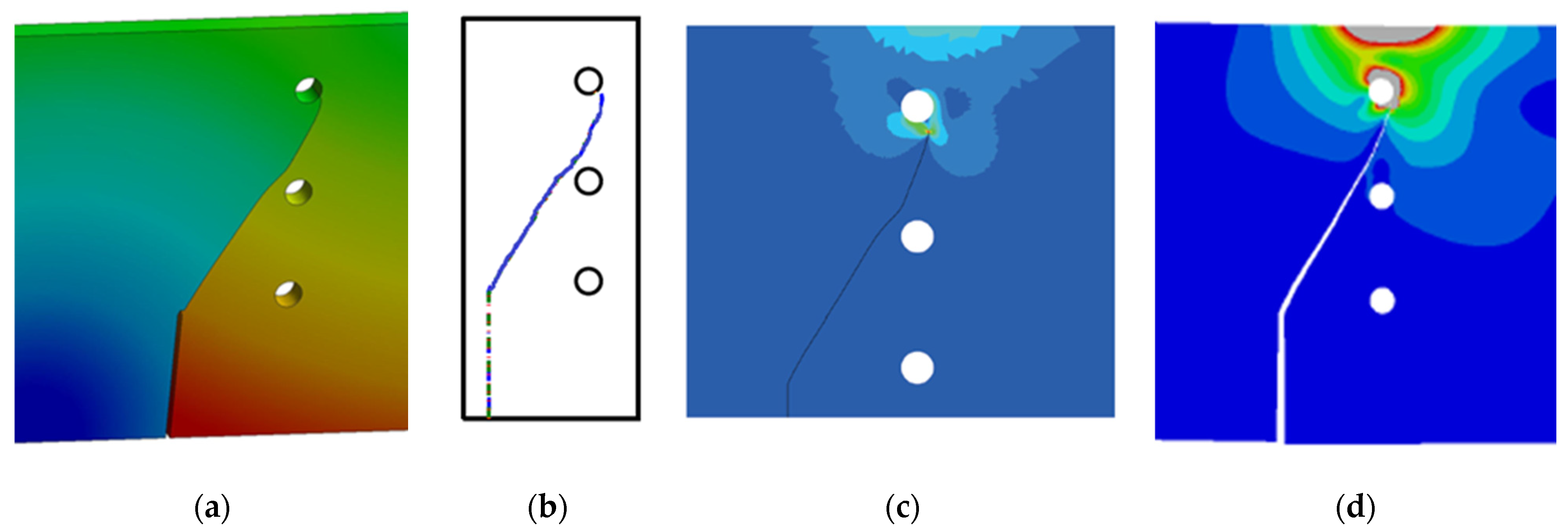
This specimen has the same outer dimensions as the one in case I, but it does not include any internal holes. Figure 8 illustrates the crack growth trajectory predicted by ANSYS, which closely aligns with the numerical path estimated by Dirik and Yalçinkaya [43], indicating a strong resemblance between the two predictions. The total deformation displayed in Figure 9 provides a visual representation of the crack growth in the hole-less specimen. It is evident that the crack propagated at a faster rate, eventually causing the specimen to fracture into two separate parts. This is in contrast to the previous specimen with holes, where the crack was effectively arrested at the middle hole, preventing further propagation. This highlights the value of using holes as crack arrestors to enhance structural integrity and prevent catastrophic failure. By redistributing stress, deflecting crack propagation, and inducing crack arrest, this technique significantly improves the reliability of various engineering structures and materials.
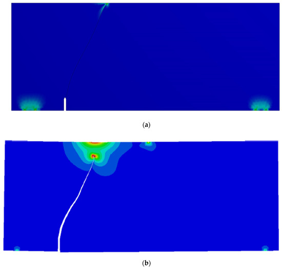
Figure 8.
Crack growth path for case II: (a) present study and (b) ABAQUS with a mesh-independent computational algorithm [43].
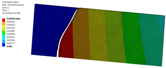
Figure 9.
Total deformation of case II specimen.
In Figure 10, the von Mises stress values for the current case are displayed, along with the numerical results obtained using ABAQUS software with a mesh-independent computational algorithm through the Dirik and Yalçinkaya [43] analysis. Notably, there is a remarkable agreement between the computed values. As depicted in the figure, it is evident that the von Mises stress for the hole-less specimen is considerably higher than that of the previous specimen with holes, as previously shown in Figure 7. This discrepancy in stress levels highlights the significance of hole presence or absence in influencing the distribution of stress and, consequently, the von Mises stress values in the material. This disparity can be attributed to the absence of stress concentration points associated with the holes in the hole-less specimen. Without the presence of holes to redistribute and alleviate stress, the crack propagation in the hole-less specimen is less impeded, leading to higher stress concentrations and, consequently, higher von Mises stress values throughout the specimen.
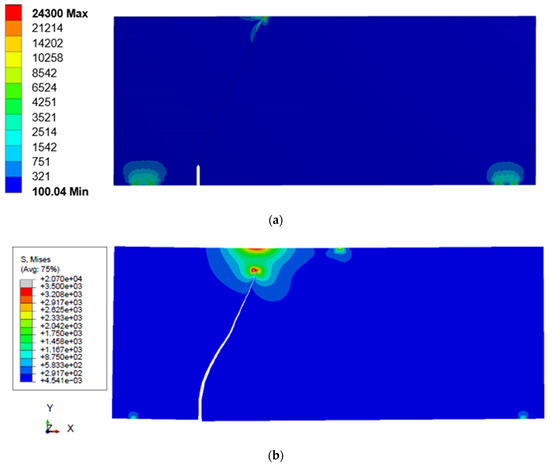
Figure 10.
Von Mises stress distribution for case II: (a) present study; (b) ABAQUS with a mesh-independent computational algorithm [43].
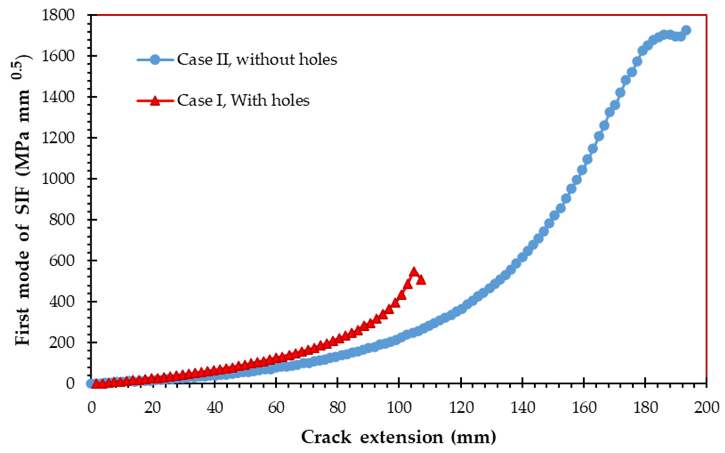
Figure 11 illustrates the calculated results of the first mode of the stress intensity factor (KI) for both case I and case II, taking into account the presence or absence of holes. The figure clearly illustrates that in case I, the stress intensity factor exhibits higher values compared to case II, even when accounting for the same crack length. As the crack continues to propagate in case II, the values of KI demonstrate a rapid and continuous increase until complete fracture occurs. The significance of holes on the stress intensity factor (SIF) is underscored by this observation, revealing distinct crack behavior in different cases. These findings highlight the importance of considering such factors in fracture mechanics and structural integrity assessments.
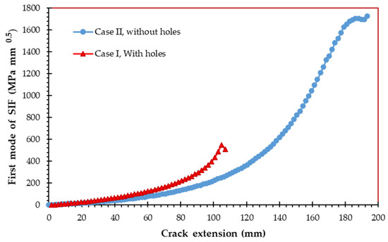
Figure 11.
First mode of stress intensity factor for case I and case II.
3.1.3. Case III
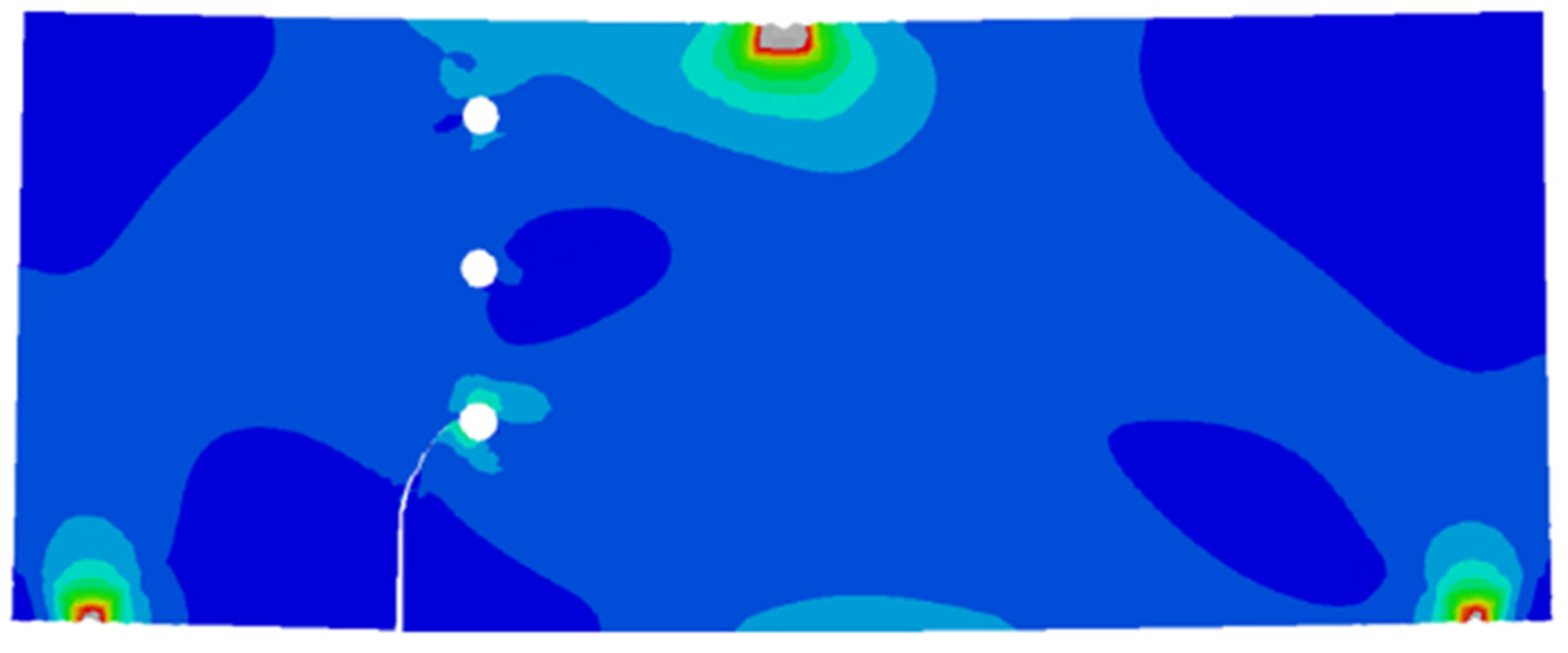
The geometry of this specimen closely resembles that of case I, with the only difference being a crack length of 63.5 mm and a crack positioned 152.4 mm away from the mid-span. Figure 12 presents the crack growth path for case III, providing a comparison between the results obtained from the ANSYS simulations in this study and the experimental crack trajectory conducted by Bittencourt et al. [45]. Additionally, the numerical findings of Peng et al. [50], who employed smooth nodal stresses in the XFEM, as well as the numerical results of Dirik and Yalçinkaya [43], who utilized a mesh-independent computational algorithm developed and integrated into ABAQUS software, are also included for reference. Figure 13 presents a comprehensive comparison of the von Mises stress distribution results for case I in the present study with the corresponding findings obtained by Dirik and Yalçinkaya [43], who utilized a mesh-independent computational algorithm integrated into the widely used commercial finite element software ABAQUS. Remarkably, a high degree of agreement is evident in both the stress distribution and stress values between the two sets of results.

Figure 12.
Crack growth path, (a) present study, (b) experimental [33], (c) XFEM [36], and (d) ABAQUS with a mesh-independent computational algorithm [43].
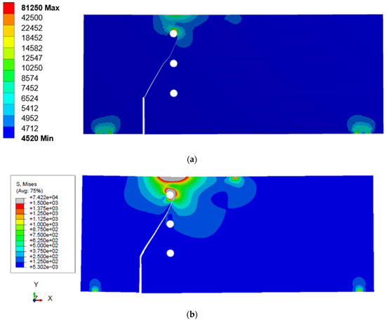
Figure 13.
Von Mises stress distribution for case III: (a) present study; (b) ABAQUS with a mesh-independent computational algorithm [43].
Figure 14 and Figure 15 provide a compelling comparison between the predicted SIFs (KI and KII) for the specimen under consideration, along with the corresponding numerical results obtained using the dual boundary method by Andrade and Leonel [46]. The agreement between the two sets of data is remarkably strong. Initially, the crack growth is predominantly influenced by mixed-mode behavior, where the higher value of the second mode of SIF plays a significant role. As the crack propagated and neared the middle hole, a slight reduction in KI and a slight increase in KII were observed. This combination of changes led to a small deviation in the crack path for a short period. However, the crack subsequently resumed its propagation towards the upper third hole, indicating the dominant influence of KI in driving crack growth. The observed variations in KI and KII highlight the complex nature of crack propagation and its sensitivity to local geometric features.
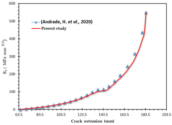
Figure 14.
Comparison for the first mode of SIF for case III [46].
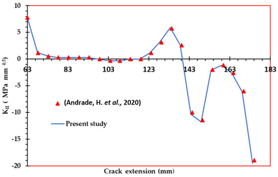
Figure 15.
Comparison for the second mode of SIF for case III [46].
3.1.4. Case IV
The dimensions of this particular specimen match those of the specimen in case III, except that it does not contain any holes. Figure 16 displays the predicted crack growth path predicted by ANSYS, as well as the distribution of von Mises stress. This predicted path is then compared to the path obtained from ABAQUS, which also considers von Mises stress and utilizes a mesh-independent computational algorithm [43]. The comparison reveals good agreement between the two predicted paths.
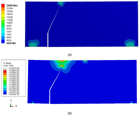
Figure 16.
Von Mises stress distribution for case IV: (a) present study; (b) ABAQUS with a mesh-independent computational algorithm [43].
It is significant to emphasize that the absence of internal holes in the specimen contributes to higher von Mises stress levels compared to the same specimen with holes, as shown in Figure 6, Figure 8, Figure 13 and Figure 16. This difference can be attributed to the fact that the presence of holes acts as stress concentrators, causing localized stress intensification. Conversely, the absence of holes enables a more uniform distribution of stress, leading to higher overall von Mises stress levels in the hole-free specimen.
4. Conclusions
This study investigated the application of ANSYS software’s Separating Morphing and Adaptive Remeshing Technology (SMART) in simulating crack growth within structures incorporating holes. This study focused on the use of holes as crack arrestors to enhance structural integrity and prevent crack propagation. By applying the maximum circumferential stress criterion and interaction integral technique, the crack growth path and stress intensity factors were estimated. The computational simulations were validated through comparison with experimental and numerical data, demonstrating the accuracy and reliability of the findings. The absence of internal holes in the specimen leads to higher von Mises stress levels compared to the specimen with holes. This difference is due to the stress concentrator effect of the holes, which causes localized stress intensification. In contrast, the absence of holes allows for a more uniform distribution of stress, resulting in higher overall von Mises stress levels in the hole-free specimen. These findings highlight the significance of holes as stress redistributors and demonstrate their role in mitigating stress concentrations and enhancing structural integrity. ANSYS SMART Crack Growth, despite its advantages, does have certain limitations. Firstly, it can only simulate crack growth for materials that adhere to linear elastic fracture mechanics. Moreover, its effective utilization necessitates a considerable level of expertise and experience, potentially limiting accessibility for some users.
Author Contributions
Conceptualization, A.M.A.; Methodology, Y.A.F. and A.M.A.; Software, A.M.A.; Validation, A.M.A.; Formal analysis, Y.A.F. and A.M.A.; Investigation, A.M.A.; Resources, Y.A.F. and A.M.A.; Data curation, Y.A.F. and A.M.A.; Writing—original draft, A.M.A.; Writing—review & editing, A.M.A.; Visualization, A.M.A.; Supervision, Y.A.F. and A.M.A.; Project administration, A.M.A.; Funding acquisition, Y.A.F. and A.M.A. All authors have read and agreed to the published version of the manuscript.
Funding
The authors extend their appreciation to the Deputyship for Research and Innovation, Ministry of Education, Saudi Arabia, for funding this research work through the project number ISP-2024.
Institutional Review Board Statement
Not applicable.
Informed Consent Statement
Not applicable.
Data Availability Statement
All relevant data are contained in the present manuscript.
Conflicts of Interest
The authors declare no conflicts of interest.
References
- Grandt, A.F., Jr. Fundamentals of Structural Integrity: Damage Tolerant Design and Nondestructive Evaluation; John Wiley & Sons: Hoboken, NJ, USA, 2003. [Google Scholar]
- Ellyin, F. Fatigue Damage, Crack Growth and Life Prediction; Springer Science & Business Media: Berlin/Heidelberg, Germany, 2012. [Google Scholar]
- Wang, Q.; Zhou, W.; Wang, Z.; Xiang, S.; Yao, G.; Huang, Q.; Liu, Y. Numerical Analysis of Fracture Behaviour for Cracked Joints in Corrugated Plate Girders Repaired by Stop-Holes. Materials 2023, 16, 3606. [Google Scholar] [CrossRef]
- Qiang, X.; Wu, Y.; Wang, Y.; Jiang, X. Novel crack repair method of steel bridge diaphragm employing Fe-SMA. Eng. Struct. 2023, 292, 116548. [Google Scholar] [CrossRef]
- Tada, H.; Paris, P.C.; Irwin, G.R.; Tada, H. The Stress Analysis of Cracks Handbook; ASME Press: New York, NY, USA, 2000; Volume 130. [Google Scholar]
- Al Laham, S.; Branch, S.I. Stress Intensity Factor and Limit Load Handbook; British Energy Generation Limited: London, UK, 1998; 3.
- Alshoaibi, A.M.; Fageehi, Y.A. 2D finite element simulation of mixed mode fatigue crack propagation for CTS specimen. J. Mater. Res. Technol. 2020, 9, 7850–7861. [Google Scholar] [CrossRef]
- Alshoaibi, A.M.; Fageehi, Y.A. A Computational Framework for 2D Crack Growth Based on the Adaptive Finite Element Method. Appl. Sci. 2022, 13, 284. [Google Scholar] [CrossRef]
- Alshoaibi, A.M.; Fageehi, Y.A. Adaptive Finite Element Model for Simulating Crack Growth in the Presence of Holes. Materials 2021, 14, 5224. [Google Scholar] [CrossRef] [PubMed]
- Bashiri, A.H. 2D and 3D numerical simulation of fatigue crack growth path and life predictions of a linear elastic. Mater. Sci.-Pol. 2021, 39, 285–297. [Google Scholar] [CrossRef]
- Mousa, S.; Mutnbak, M.; Saba, A.-A.M.; Abd-Elhady, A.A.; Sallam, H.E.-D.M. Numerical study and experimental validation of the size effect of smooth and mode I cracked semi-circular bend specimens. Sci. Rep. 2023, 13, 7570. [Google Scholar] [CrossRef]
- Mousa, S.; Mutnbak, M.; Abd-Elhady, A.A.; Sallam, H.E.-D.M.; Reda, R.M. The efficiency of advanced polymeric composite sleeves in the rehabilitation of cracked pipelines under combined loadings. J. Mater. Res. Technol. 2023, 25, 6395–6406. [Google Scholar] [CrossRef]
- Ammendolea, D.; Greco, F.; Leonetti, L.; Lonetti, P.; Pascuzzo, A. Fatigue crack growth simulation using the moving mesh technique. Fatigue Fract. Eng. Mater. Struct. 2023, 46, 4606–4627. [Google Scholar] [CrossRef]
- Zhou, S.; Rabczuk, T.; Zhuang, X. Phase field modeling of quasi-static and dynamic crack propagation: COMSOL implementation and case studies. Adv. Eng. Softw. 2018, 122, 31–49. [Google Scholar] [CrossRef]
- Zhang, X.; Li, L.; Qi, X.; Zheng, J.; Zhang, X.; Chen, B.; Feng, J.; Duan, S. Experimental and numerical investigation of fatigue crack growth in the cracked gear tooth. Fatigue Fract. Eng. Mater. Struct. 2017, 40, 1037–1047. [Google Scholar] [CrossRef]
- Wang, W.; Ni, K.; Ma, H.; Xiong, Q.; Wu, Z.; Wang, H.; Fan, C. Fatigue crack propagation simulation of airfoil section blade under aerodynamic and centrifugal loads. Eng. Fract. Mech. 2023, 293, 109702. [Google Scholar] [CrossRef]
- Poursaeidi, E.; Kavandi, A.; Vaezi, K.; Kalbasi, M.; Arhani, M.M. Fatigue crack growth prediction in a gas turbine casing. Eng. Fail. Anal. 2014, 44, 371–381. [Google Scholar] [CrossRef]
- Main, B.; Jones, M.; Barter, S. The practical need for short fatigue crack growth rate models. Int. J. Fatigue 2021, 142, 105980. [Google Scholar] [CrossRef]
- Skorupa, M.; Machniewicz, T.; Schijve, J.; Skorupa, A. Application of the strip-yield model from the NASGRO software to predict fatigue crack growth in aluminium alloys under constant and variable amplitude loading. Eng. Fract. Mech. 2007, 74, 291–313. [Google Scholar] [CrossRef]
- Lee, G.-B.; Park, S.-H.; Jang, Y.-Y.; Huh, N.-S.; Park, S.-H.; Park, N.-H.; Park, J. Development of automatic crack growth simulation program based on finite element analysis. Appl. Sci. 2022, 12, 3075. [Google Scholar] [CrossRef]
- Nakamura, H.; Matsushima, E.; Okamoto, A.; Umemoto, T. Fatigue crack growth under residual stress field in low-carbon steel. Nucl. Eng. Des. 1986, 94, 241–247. [Google Scholar] [CrossRef]
- Li, X.; Li, H.; Liu, L.; Liu, Y.; Ju, M.; Zhao, J. Investigating the crack initiation and propagation mechanism in brittle rocks using grain-based finite-discrete element method. Int. J. Rock Mech. Min. Sci. 2020, 127, 104219. [Google Scholar] [CrossRef]
- Leclerc, W.; Haddad, H.; Guessasma, M. On the suitability of a Discrete Element Method to simulate cracks initiation and propagation in heterogeneous media. Int. J. Solids Struct. 2017, 108, 98–114. [Google Scholar] [CrossRef]
- Shao, Y.; Duan, Q.; Qiu, S. Adaptive consistent element-free Galerkin method for phase-field model of brittle fracture. Comput. Mech. 2019, 64, 741–767. [Google Scholar] [CrossRef]
- Kanth, S.A.; Harmain, G.; Jameel, A. Modeling of Nonlinear Crack Growth in Steel and Aluminum Alloys by the Element Free Galerkin Method. Mater. Today Proc. 2018, 5, 18805–18814. [Google Scholar] [CrossRef]
- Surendran, M.; Natarajan, S.; Palani, G.; Bordas, S.P. Linear smoothed extended finite element method for fatigue crack growth simulations. Eng. Fract. Mech. 2019, 206, 551–564. [Google Scholar] [CrossRef]
- Rozumek, D.; Marciniak, Z.; Lesiuk, G.; Correia, J. Mixed mode I/II/III fatigue crack growth in S355 steel. Procedia Struct. Integr. 2017, 5, 896–903. [Google Scholar] [CrossRef]
- Dekker, R.; van der Meer, F.; Maljaars, J.; Sluys, L. A cohesive XFEM model for simulating fatigue crack growth under mixed-mode loading and overloading. Int. J. Numer. Methods Eng. 2019, 118, 561–577. [Google Scholar] [CrossRef]
- Rezaei, S.; Wulfinghoff, S.; Reese, S. Prediction of fracture and damage in micro/nano coating systems using cohesive zone elements. Int. J. Solids Struct. 2017, 121, 62–74. [Google Scholar] [CrossRef]
- Peng, X.; Atroshchenko, E.; Kerfriden, P.; Bordas, S.P.A. Isogeometric boundary element methods for three dimensional static fracture and fatigue crack growth. Comput. Methods Appl. Mech. Eng. 2017, 316, 151–185. [Google Scholar] [CrossRef]
- Leonel, E.D.; Chateauneuf, A.; Venturini, W.S. Probabilistic crack growth analyses using a boundary element model: Applications in linear elastic fracture and fatigue problems. Eng. Anal. Bound. Elem. 2012, 36, 944–959. [Google Scholar] [CrossRef]
- Citarella, R.; Giannella, V.; Lepore, M.; Dhondt, G. Dual boundary element method and finite element method for mixed-mode crack propagation simulations in a cracked hollow shaft. Fatigue Fract. Eng. Mater. Struct. 2018, 41, 84–98. [Google Scholar] [CrossRef]
- Zhang, W.; Tabiei, A. An Efficient Implementation of Phase Field Method with Explicit Time Integration. J. Appl. Comput. Mech. 2020, 6, 373–382. [Google Scholar]
- Jorge Guillermo, G.L.G.G.; Ortiz González, J.A.; Freire, J. Analysis of Mixed-mode Stress Intensity Factors using Digital Image Correlation Displacement Fields. In Proceedings of the 24th ABCM International Congress of Mechanical Engineering, Curitiba, Brazil, 3–8 December 2017; ABCM: Curitiba, Brazil, 2017. [Google Scholar]
- Chatzigeorgiou, A.; Theotokoglou, E.; Tsamasphyros, G.I. Code development for the computational analysis of crack propagation in structures. Frat. Ed Integrità Strutt. 2020, 14, 306–324. [Google Scholar] [CrossRef]
- Alshoaibi, A.M.; Bashiri, A.H. Fatigue Crack Growth Studies under Mixed-Mode Loading in AISI 316 Stainless Steel. Appl. Sci. 2023, 13, 9446. [Google Scholar] [CrossRef]
- Alshoaibi, A.M.; Fageehi, Y.A. 3D modelling of fatigue crack growth and life predictions using ANSYS. Ain Shams Eng. J. 2022, 13, 101636. [Google Scholar] [CrossRef]
- Alshoaibi, A.M.; Fageehi, Y.A. Finite Element Simulation of a Crack Growth in the Presence of a Hole in the Vicinity of the Crack Trajectory. Materials 2022, 15, 363. [Google Scholar] [CrossRef] [PubMed]
- Alshoaibi, A.M.; Fageehi, Y.A. Numerical Analysis of Fatigue Crack Growth Path and Life Predictions for Linear Elastic Material. Materials 2020, 13, 3380. [Google Scholar] [CrossRef]
- Bjørheim, F. Practical Comparison of Crack Meshing in ANSYS Mechanical APDL 19.2; University of Stavanger: Stavanger, Norway, 2019. [Google Scholar]
- ANSYS. Academic Research Mechanical, Release 19.2, Help System; Coupled Field Analysis Guide; ANSYS, Inc.: Canonsburg, PA, USA, 2020. [Google Scholar]
- Azócar, D.; Elgueta, M.; Rivara, M.C. Automatic LEFM crack propagation method based on local Lepp–Delaunay mesh refinement. Adv. Eng. Softw. 2010, 41, 111–119. [Google Scholar] [CrossRef]
- Dirik, H.; Yalçinkaya, T. Crack path and life prediction under mixed mode cyclic variable amplitude loading through XFEM. Int. J. Fatigue 2018, 114, 34–50. [Google Scholar] [CrossRef]
- Mohmadsalehi, M.; Soghrati, S. An automated mesh generation algorithm for simulating complex crack growth problems. Comput. Methods Appl. Mech. Eng. 2022, 398, 115015. [Google Scholar] [CrossRef]
- Bittencourt, T.; Wawrzynek, P.; Ingraffea, A.; Sousa, J. Quasi-automatic simulation of crack propagation for 2D LEFM problems. Eng. Fract. Mech. 1996, 55, 321–334. [Google Scholar] [CrossRef]
- Andrade, H.; Leonel, E. An enriched dual boundary element method formulation for linear elastic crack propagation. Eng. Anal. Bound. Elem. 2020, 121, 158–179. [Google Scholar] [CrossRef]
- Fu, Q.; Yi, S.; Chen, B.; Bui, T.Q.; Hu, X.; Yao, W. A crack-tip element for modelling arbitrary crack propagations. Theor. Appl. Fract. Mech. 2020, 105, 102422. [Google Scholar] [CrossRef]
- Huynh, H.D.; Nguyen, M.N.; Cusatis, G.; Tanaka, S.; Bui, T.Q. A polygonal XFEM with new numerical integration for linear elastic fracture mechanics. Eng. Fract. Mech. 2019, 213, 241–263. [Google Scholar] [CrossRef]
- Ma, W.; Liu, G.; Wang, W. A coupled extended meshfree–smoothed meshfree method for crack growth simulation. Theor. Appl. Fract. Mech. 2020, 107, 102572. [Google Scholar] [CrossRef]
- Peng, X.; Kulasegaram, S.; Wu, S.; Bordas, S.P.A. An extended finite element method (XFEM) for linear elastic fracture with smooth nodal stress. Comput. Struct. 2017, 179, 48–63. [Google Scholar] [CrossRef]


Disclaimer/Publisher’s Note: The statements, opinions and data contained in all publications are solely those of the individual author(s) and contributor(s) and not of MDPI and/or the editor(s). MDPI and/or the editor(s) disclaim responsibility for any injury to people or property resulting from any ideas, methods, instructions or products referred to in the content. |
© 2024 by the authors. Licensee MDPI, Basel, Switzerland. This article is an open access article distributed under the terms and conditions of the Creative Commons Attribution (CC BY) license (https://creativecommons.org/licenses/by/4.0/).