Abstract
This paper aims to predict the damage and fracture behavior of thermoplastic fiber-reinforced metal laminates (TFMLs) under ballistic impact loadings. A dynamic metal constitutive model has been employed and implemented in Abaqus/Explicit through a vectorized user material subroutine (VUMAT). The effects of the Lode angle, temperature, and strain rate are considered in the strength model, while the effects of stress triaxiality, Lode angle, temperature, and strain rate are taken into account in the failure criteria. To assess the validity and superiority of the proposed model, the numerically predicted responses of polypropylene fiber-reinforced metal laminates subjected to varying impact energies were systematically compared with corresponding experimental results. Additionally, a comparative analysis was performed between the numerical simulation results predicted by the present model and those obtained using other constitutive models, such as the Johnson–Cook (JC) constitutive model and the elastoplastic constitutive model. Furthermore, the effect of projectile types on the ballistic performance of TFMLs have been systematically investigated. The findings demonstrate that the failure pattern predicted by the current model closely aligns with the experimental observations, while both the Johnson–Cook (JC) constitutive model and the elastoplastic constitutive model were unable to accurately replicate the experimentally observed failure behavior. This study also reveals that the projectile’s nose shape plays a significant role in influencing the perforation behavior of TFMLs, affecting both the residual velocity and damage.
1. Introduction
Fiber–metal laminates (FMLs), also known as FMLs, are formed by alternately layering FRP composite layers and metal layers under high temperatures and pressure [1,2]. Thermoplastic fiber–metal laminates (TFMLs), showing higher toughness and lower cost compared to traditional thermoset-based fiber-reinforced metal laminates, are widely employed in defense and industrial areas due to their low density, good impact resistance, as well as ease of fabrication [3,4,5,6]. However, it may be subjected to loading from dropped objects or projectile impacts during its operational lifespan [7]. The failure mechanisms of TFMLs under projectile impact are highly intricate, encompassing the deformation and damage of metal plates, as well as tensile, compressive, and shear failures within the composite laminates [8].
Yang et al. [9] investigated the impact resistance and damage tolerance of thermoplastic FMLs, which are composed of metal layers combined with ultra-high-molecular-weight polyethylene (UHMWPE) fiber. It has been found that the metal absorbed a significant amount of energy through localized plastic deformation induced by membrane tension. Similar energy absorption mechanisms were also experimentally observed, such as plastic deformation of aluminum sheets, fracture failure, damage to the composite material layer, as well as delamination [10]. Majzoobi et al. [11] observed that the aluminum alloy layer in FMLs exhibit a petal-like failure morphology based on experimental studies. Furthermore, experimental observations have demonstrated the strain-rate effect on FMLs subjected to impact loadings [12,13].
Guan et al. [14] performed a comprehensive numerical analysis to examine the behavior of polypropylene fiber-reinforced metal laminates under impact loadings. The composite layers in their study comprised woven polypropylene fiber-reinforced polypropylene matrix composites (PP/PP), widely used thermoplastic composite materials. Elastoplastic constitutive models were employed in the analysis of both metallic and composite materials. The numerical prediction of the maximum permanent displacement exhibits a high degree of concordance with the experimental results. However, there is a significant discrepancy between the predicted failure morphology of the target plate and the observed experimental results. Linde et al. [15] also employed elastoplastic constitutive models for metals. Nevertheless, these models are overly simplistic and inadequate for capturing the complex responses of materials. Residual velocity and ballistic limit under high-speed impacts are primarily emphasized by current models [16], with the prediction of damage morphology for the target plate often being overlooked. The precise prediction of the dynamic response of the metal layer in FMLs subjected to impact loads depends critically on the selection of suitable metal constitutive models and failure criteria. The response of metals under impact loads is often modelled using the JC constitutive model and failure criteria, which frequently fail to accurately predict damage and fracture failure morphology [17,18,19]. Zhou et al. [20] evaluated the JC constitutive model and failure criteria, finding that the model’s prediction results agree with experimental observations at low strain rates and temperatures. However, significant discrepancies with test data were observed at high strain rates and temperatures, affecting the accurate prediction of damage and fracture for metals under impact loadings.
This paper aims to investigate the damage and fracture behavior of thermoplastic fiber-reinforced metal laminates subjected to high-speed projectile impacts through numerical simulations employing a modified metal constitutive model. To validate the model’s accuracy, a comparative analysis will be conducted for the numerical results and the experimental data from ballistic impact tests on polypropylene fiber-reinforced metal laminates subjected to varying impact energies. Additionally, comparisons will be conducted with predictions using existing models (JC+BW). Moreover, the effect of varying projectile nose geometries on the ballistic performance of the TFMLs will be systematically examined, with a particular emphasis on the intensity of failure patterns.
2. Dynamic Constitutive Model for 2024-T3 Aluminum Alloy
2.1. Strength Model
Drawing on extensive experimental data and existing research findings [20,21,22], the strength model for metals under varying temperature, stress conditions, and strain rates is proposed as follows:
where , are equivalent stress and equivalent plastic strain, respectively. The values of material parameters are determined by quasi-static tensile experiments. is defined as the ratio of shear equivalent stress to tensile equivalent stress. The Lode angle parameter , related to the angle θ of π plane (, ), is expressed as follows:
where are the second and third invariant of the stress–deviator tensor. () is the dimensionless temperature, with being the current, ambient, and melting temperatures, respectively. The material parameters can be experimentally determined through high-temperature experiments. The Dynamic Increase Factor (DIF), which describes the strain-rate effect on metals, is determined by both the magnitude of the strain rate and the plastic deformation of the metal, as expressed below [22]:
where , the Dynamic Increase Factor at a given plastic-strain level, can be formulated as follows:
denotes the reference strain rate, usually taken as , and is the quasi-static strain rate, which is usually less than .
2.2. Failure Criteria
The failure criteria for metals, as proposed by Zhou and Wen [21,22], are influenced by factors including stress triaxiality, Lode angle, strain-rate effect, and temperature effect, and can be expressed as follows:
where are failure strain, stress triaxiality, and Lode angle, respectively. The stress triaxiality is defined by the following equation:
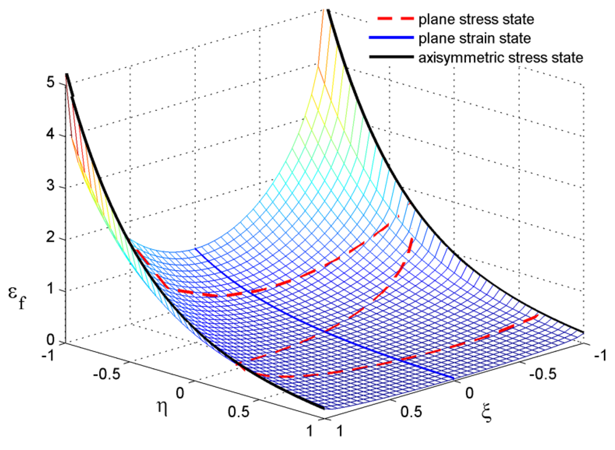
where . are materials constants that can be determined through smooth-round-bar tensile and pure-shear experiments, respectively. In the uniaxial tensile test, the condition is satisfied, whereas in the torsion experiment, the condition is met. Figure 1 shows the three-dimensional schematic diagram illustrating the relationship between fracture strain, stress triaxiality, and Lode angle ().

Figure 1.
A three-dimensional schematic diagram illustrating the relationship between fracture strain, stress triaxiality, and Lode angle (), with black line being axisymmetric stress state, blue solid line being plane strain state, red dashed line being the stress state of the plane stress state.
3. Formulation of Finite Element Model
The constitutive model presented in Section 2 will be implemented as a VUMAT subroutine, and the finite element (FE) model will be developed using ABAQUS/Explicit (V6.11) to examine the impact response of TFMLs subjected to projectile impact.
3.1. Finite Element Model
Figure 2 illustrates the finite element (FE) model for the fiber–metal laminates (FMLs) comprising a polypropylene (PP) fiber/PP matrix composite (Curv from Propex Fabric), subjected to impact by a hemispheric-nosed projectile at varying impact energies. A nitrogen gas gun was utilized to evaluate the high-velocity impact response of FMLs. The cross-sections were polished and subsequently analyzed using optical microscopy [23]. The impactor has a mass of 46.7 g with 12.7 mm diameter. The panel (100 mm × 100 mm × 5.73 mm), clamped in a fixture with an 80 mm × 80 mm opening, was composed of 4 layers of woven PP fiber-reinforced PP composite (PP/PP) and 5 layers of 2024-T3(from Alcan) aluminum alloy [23], arranged as [Al/PP/Al/PP/Al/PP/Al/PP/Al]. The total thickness of the panel was 5.73 mm, with each layer of 2024-T3 aluminum alloy being 0.8 mm. To enhance computational efficiency, a fine mesh with an element size of 1.0 mm × 1.0 mm was employed in the impact region. The general contact algorithm was employed to simulate the contact interactions, incorporating a friction coefficient of 0.2 within the contact formulation. Assuming the impactor maintains its rigidity throughout the collision, C3D8R solid elements were utilized for all components. A fixed boundary condition was applied to the supporting area in the finite element models.
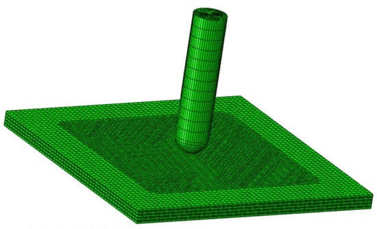
Figure 2.
The FE model for the FMLs panel struck by a hemispheric-nosed projectile.
3.2. Determination of Various Parameters
Table 1 presents the values of material parameters for the present model, whereas Table 2 provides the parameters for the Johnson–Cook (JC) strength model and the failure criterion proposed by Bai and Wierzbicki [24] (JC(+BW)) for metals. It should be mentioned here that the values of in Table 1 are evaluated through a curve-fitting methodology with the experimental data provided in reference [25] as shown in Figure 3. The other material parameters of 2024-T3 aluminum alloy in Table 1 are referred to the references [7]. PP/PP is modelled as an isotropic, perfect plastic material, with an elastic modulus of E = 4.2 GPa, Poisson’s ratio , density , and yield strength , as reported by Guan et al. [14].

Table 1.
Values of various parameters in the present model for 2024-T3 aluminum alloy [7,25].
Table 2.
Values of various parameters for 2024-T3 aluminum alloy in JC(+BW) model [7,24].
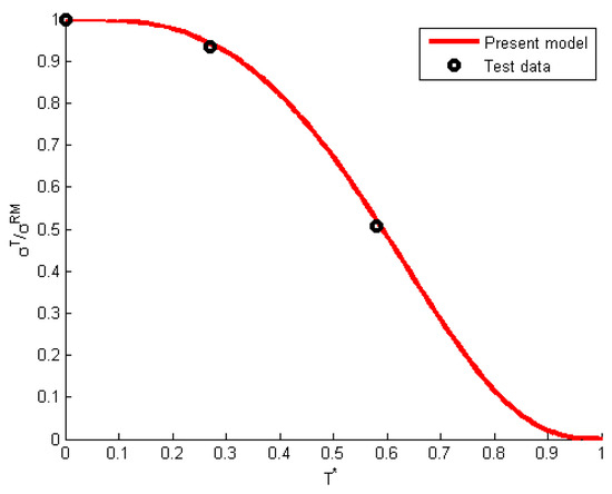
Figure 3.
The relationship between and T* at a plastic strain of 0.14.
4. Results and Discussion
4.1. Comparisons with Available Test Data
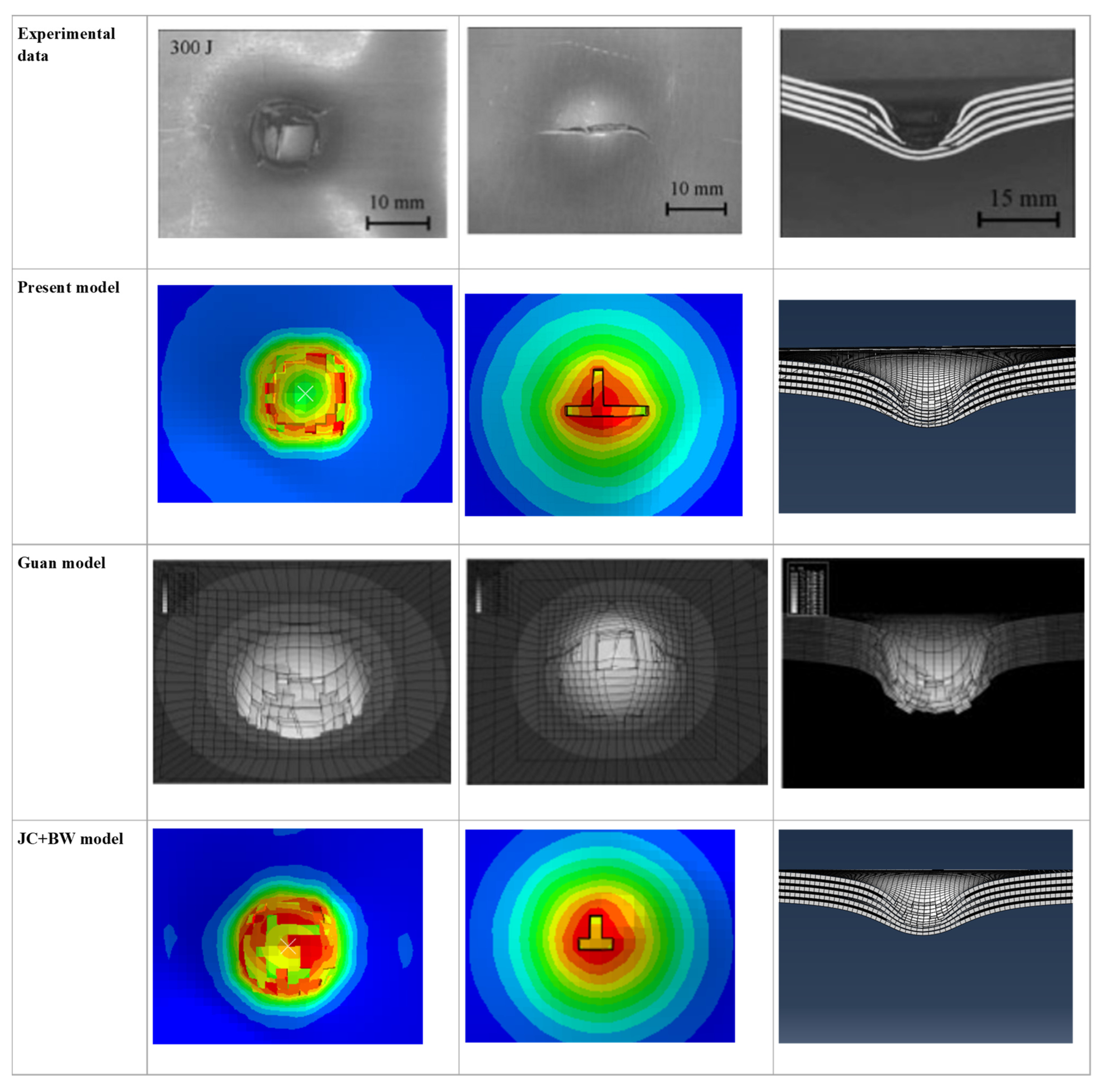
Figure 4 presents a comparative analysis of numerical predictions and experimental data for 5.73 mm thick fiber–metal laminates (FMLs), which are constructed from polypropylene (PP) fiber and PP matrix composites. These laminates were subjected to a transverse impact by a hemispherical impactor weighing 46.7 g with a diameter of 12.7 mm, delivering an impact energy of 300 J with a corresponding impact velocity of 113 m/s [7]. The material parameters utilized in the numerical simulations are detailed in Table 1 and Table 2. The numerical predicted results obtained by Guan et al. [14], who employed the elastoplastic model for both metal and PP/PP materials, are also presented in the figure, alongside the numerical results derived by the authors using the JC + BW model for 2024-T3 aluminum. It is evident that the failure patterns of FMLs predicted by the current model exhibit strong concordance with the test results. It also reveals that the failure pattern on the rear face predicted by the present model aligns more closely with the experimentally observed failure patterns than those predicted by the Guan model and the JC + BW model. Although the JC constitutive model effectively predicts the hole-opening on the impact face and cross-sectional deformation, it fails to provide an accurate forecast of the initial crack propagation. Prior to penetration by the projectile, the aluminum alloy can fully deform independently and absorb energy due to the superior plastic properties of PP/PP between aluminum alloy layers. As damage to the metal accumulates to a critical threshold, initial cracks develop, ultimately resulting in tearing failure on the rear surface.
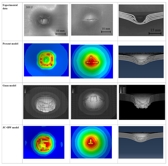
Figure 4.
Comparison between the numerical predicted results and experimental observations at an impact energy of 300 J (The color represents the degree of damage).
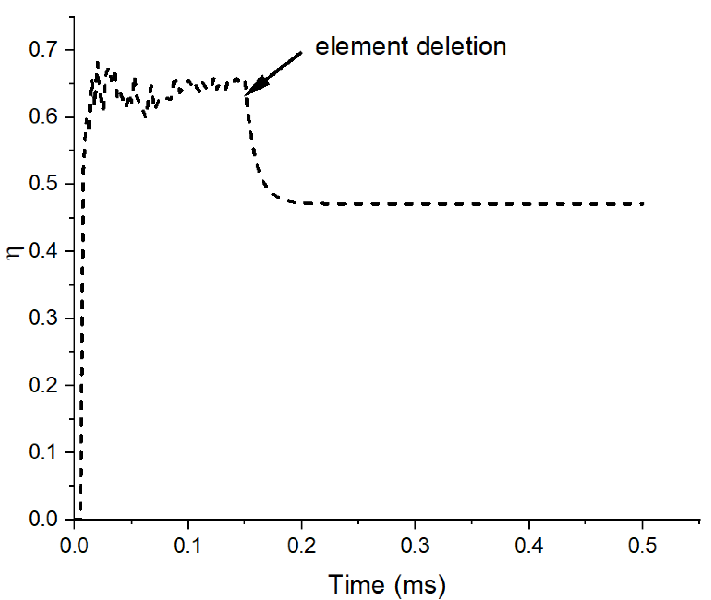
The stress triaxiality–time history at the central point on the rear surface is illustrated in Figure 5. Prior to the removal of the element, the value of stress triaxiality remained consistently stable at approximately 0.65. Under impact loading, the rear surface will experience tensile deformation, whilst compressive deformation will occur in the thickness direction due to the contact between the projectile and target. As a result, this element is subjected to in-plane tensile stress and compressive stress in the thickness direction, which is different from the stress state of uniaxial tension (i.e., ), thereby leading to distinct fracture characteristics, as shown in Figure 4.
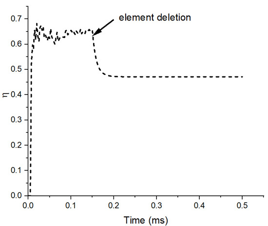
Figure 5.
Stress triaxiality–time history of the center point of the target plate at the rear surface.
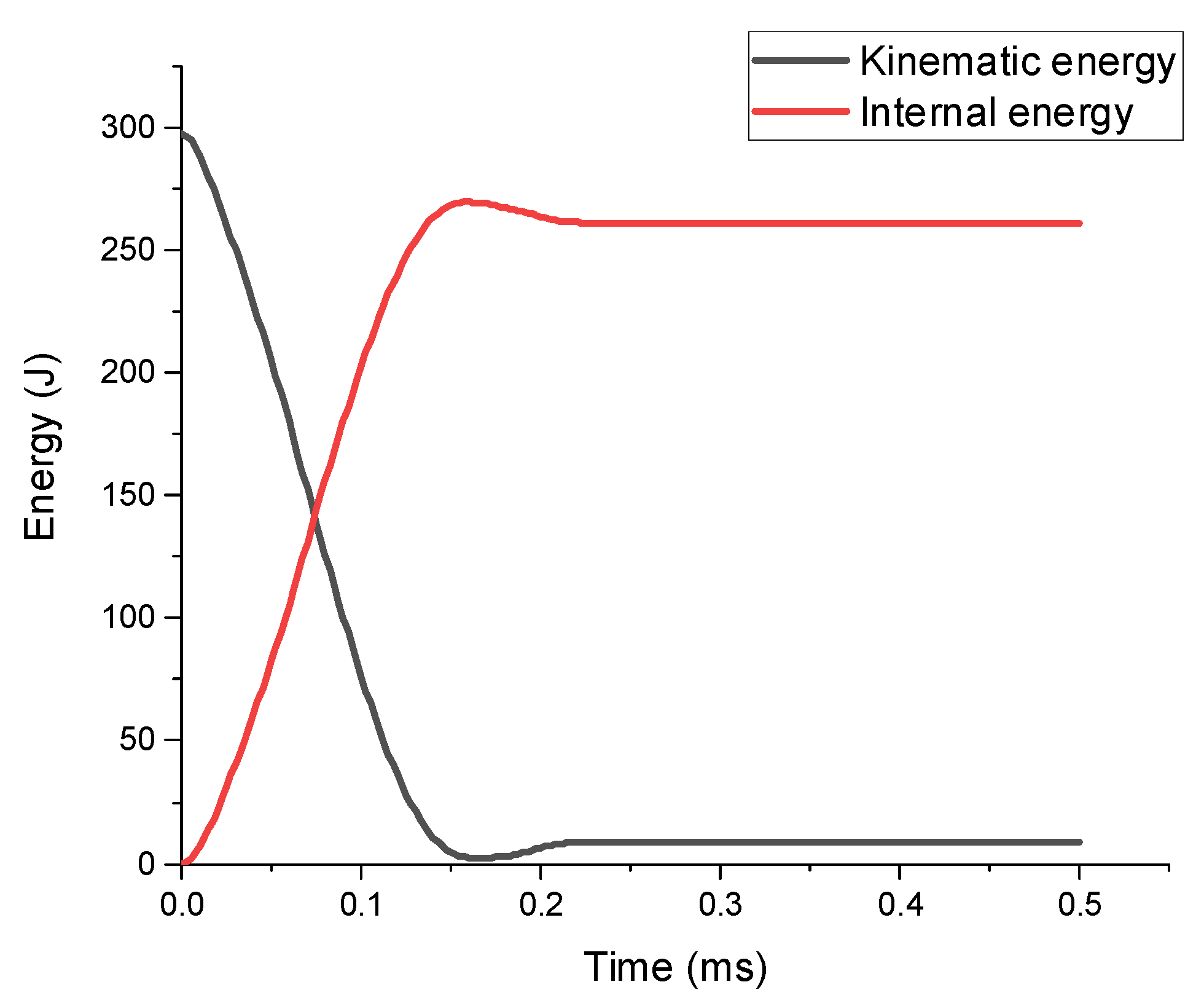
Figure 6 shows energy–time histories at an impact energy of 300 J. It is evident from Figure 6 that the initial impact kinetic energy of 300 J from the bullet is continuously dissipated, with the crack’s initial propagation reaching a point at 0.15 ms, where its kinetic energy approaches zero. At this stage, the kinetic energy of the projectile is converted into the internal energy of the target plate, primarily comprising elastic and plastic strain energies, stored due to the material’s deformation. Subsequently, the projectile rebounds, resulting in a slight increase in its kinetic energy and a corresponding decrease in the internal energy.
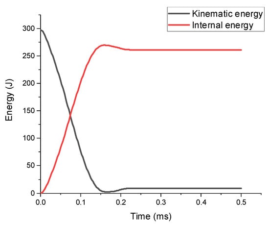
Figure 6.
Energy–time histories at an impact energy of 300 J.
Figure 7 presents a comparison between the numerically predicted results and the experimental observations for 5.73 mm thick FMLs. The FMLs, composed of a polypropylene (PP) fiber/PP matrix composite, were subjected to transverse impact by a 46.7 g hemispherical impactor with a diameter of 12.7 mm, delivering an impact energy of 353 J (impact velocity of 113 m/s) [23]. The material parameter values employed in the numerical simulations are detailed in Table 1 and Table 2. It is evident from Figure 7 that the damage modes of the impact surface as well as the rear surface and the deformation of the cross-section predicted by the present model agrees well with the experimental observations. It is also evident from Figure 7 that the failure pattern predicted by the present model exhibits superior accuracy compared to the predictions obtained from the JC + BW model and the approach by Guan et al. [14]. It is also clear from Figure 7 that the present model successfully reproduces the main feature of the petal-shaped crack on the rear surface, whereas the JC + BW constitutive model fails to reproduce this damage pattern. The present model accurately predicts the evolution of the rear surface crack from an initial unidirectional main crack to a petal-shaped crack with increasing impact energy, primarily due to the failure criteria, which incorporate the effects of stress triaxiality, Lode angle, and strain rate.
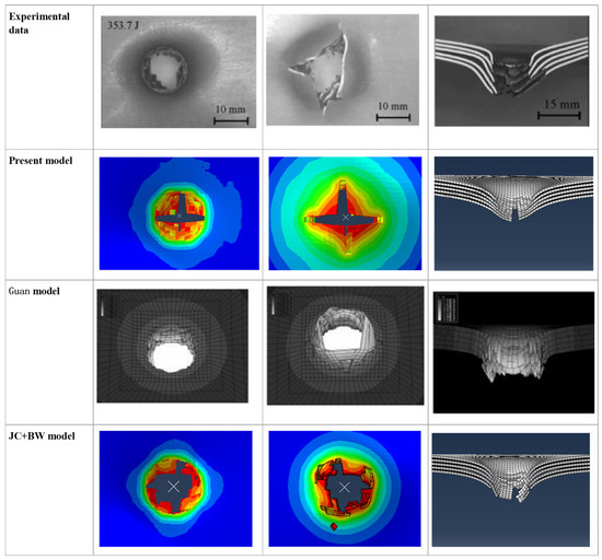
Figure 7.
Comparison between the numerical predicted results and experimental observations at an impact energy of 353 J (The color represents the degree of damage).
It is noteworthy that the appearance of the initial unidirectional crack on the rear surface of the target plate is a common phenomenon associated with the ballistic limit, as similarly observed by Moriniere et al. [26] in their impact experiments on FMLs.
4.2. Effect of Projectile Nose Shape
Figure 8 presents schematic diagrams of various projectile nose shapes (i.e., flat-nosed, ogival-nosed, and hemispheric-nosed), commonly utilized in experimental, theoretical, and numerical studies. Notably, all projectile types share identical diameter, mass, and density values, resulting in slight variations in their lengths.
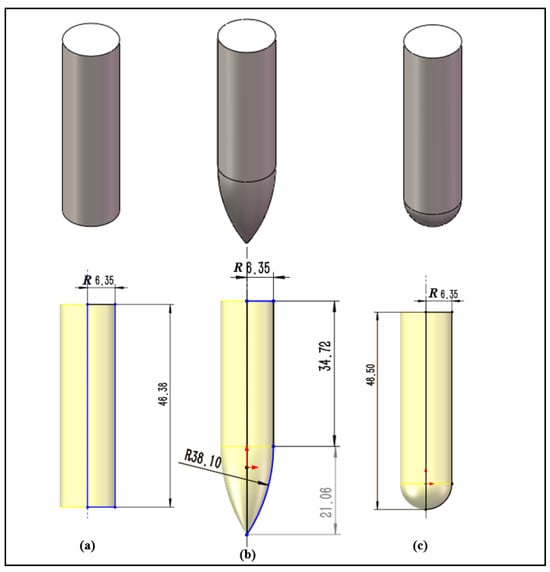
Figure 8.
Schematic diagrams of different types of projectile nose shapes: (a) flat-nosed, (b) ogival-nosed, (c) hemispheric-nosed.
Figure 9 shows the numerically predicted cross-section as well as rear surface damage patterns for the FMLs (based on a PP/PP composite) struck transversely by the 12.7 mm diameter, 46.7 g projectiles at 300 m/s with different nose shapes. The total thickness of the panel is 5.73 mm and its other parameters are consistent with the target plate introduced in Section 3. SDV7 is defined as the damage variable, with a value of zero indicating that the material remains intact and undamaged, and a value of one indicating complete destruction. When subjected to impact by a flat-nosed projectile, the target plate primarily experiences tensile and shear deformation, with the damage localized around the perforation area, as shown in Figure 9a. However, when impacted by hemispheric- and ogival-nosed bullets, the rear surface of the target plate shows a tearing failure pattern, with damage concentrated in the tearing regions, allowing the target plate to absorb more energy through this type of deformation.

Figure 9.
Numerically predicted cross-sectional as well as rear surface damage patterns for the FMLs (based on a PP/PP composite) struck transversely by the 12.7 mm diameter, 46.7 g projectiles at 300 m/s with different nose shapes. (a) Flat-nosed; (b) ogival-nosed; (c) hemispheric-nosed.
Figure 10 shows numerically the predicted residual velocity for FMLs (based on a PP/PP composite) struck transversely by the 12.7 mm diameter, 46.7 g projectiles at 300 m/s with different nose shapes. It is clear from Figure 10 that the residual velocity is greatest for the flat-nosed projectile, measuring 270 m/s, in comparison to the residual velocities of both the ogival-nosed and hemispheric-nosed projectiles, as the tearing damage induced by the latter enables the target plate to absorb a greater amount of energy.
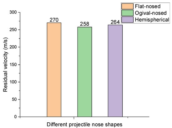
Figure 10.
Numerically predicted residual velocity for FMLs (based on a PP/PP composite) struck transversely by the 12.7 mm diameter, 46.7 g projectiles at 300 m/s with different nose shapes.
5. Conclusions
In this paper, an FE model has been developed to predict the ballistic response of thermoplastic fiber–metal laminates (TFMLs) subjected to projectile impacts at varying energy levels. The dynamic constitutive models for metal have been described. The effects of the Lode angle, temperature, and strain rate are considered in the strength model, while the effects of stress triaxiality, Lode angle, temperature, and strain rate are taken into account in the failure criteria. Additionally, the impact of the projectile’s nose shape has been investigated. The main conclusions are as follows:
- (1)
- The present model predicts the experimental results well for TFMLs subjected to impact by hemispheric-nosed projectiles in terms of perforation energy, cross-sectional deformation, and failure patterns at various impact energies.
- (2)
- It has been demonstrated that the nose shape of projectiles significantly influences the perforation behavior of TFMLs in terms of both residual velocity and damage patterns. This is attributable to the distinct deformation mechanisms induced by each projectile type. Specifically, flat-ended projectiles exhibit the highest residual velocities, whereas ogival-nosed projectiles exhibit the lowest.
- (3)
- The present model exhibits an enhanced performance regarding failure patterns when compared to existing models, such as the elastoplastic constitutive model and the JC + BW constitutive model, despite yielding comparable deformation results.
Author Contributions
Conceptualization, Y.Z. and Y.L.; methodology, Y.L.; software, Y.L.; validation, Y.Z., Y.L., H.Z. and C.L.; formal analysis, Y.L.; investigation, Y.Z. and Y.L.; resources, Y.L.; data curation, Y.L.; writing—original draft preparation, Y.L.; writing—review and editing, Y.Z., Y.L., H.Z. and C.L.; visualization, Y.L.; supervision, H.Z. and C.L.; project administration, Y.L.; funding acquisition, Y.Z. and Y.L. All authors have read and agreed to the published version of the manuscript.
Funding
This study was supported by the Guizhou University Doctoral Fund [grant (2022) 34], Basic Research Project of Guizhou University (grant (2023) 42).
Institutional Review Board Statement
Not applicable.
Informed Consent Statement
Not applicable.
Data Availability Statement
Data is contained within the article.
Conflicts of Interest
The authors declare no conflict of interest.
Abbreviations
The following abbreviations are used in this manuscript:
| TFMLs | thermoplastic fiber-reinforced metal laminates |
| VUMAT | vectorized user material subroutine |
| JC | Johnson–Cook |
| PP/PP | polypropylene fiber-reinforced polypropylene matrix composites |
| DIF | Dynamic Increase Factor |
| FE | finite element |
References
- Das, R.; Chanda, A.; Brechou, J.; Banerjee, A. Impact behaviour of fibre–metal laminates. In Dynamic Deformation, Damage and Fracture in Composite Materials and Structures; Silberschmidt, V.V., Ed.; Woodhead Publishing: Cambridge, UK, 2016; pp. 491–542. [Google Scholar]
- Xie, M.; Zhan, L.; Ma, B.; Hui, S. Classification of fiber metal laminates (FMLs), adhesion theories and methods for improving interfacial adhesion: A review. Thin-Walled Struct. 2024, 198, 111744. [Google Scholar] [CrossRef]
- Guo, Y.; Xu, X.; Chen, Z.; Yin, H.; Li, F. Deformation mechanisms and Surface/Interface characteristics of titanium-based thermoplastic FMLs under ultrasonic impact loading. Ultrasonics 2024, 138, 107217. [Google Scholar] [CrossRef]
- Sang, L.; Xing, J.; Lv, J.; Gao, S.; Hou, W. Investigation of structure–flexural response relations in thermoplastic carbon/glass fiber-metal laminates. Polym. Compos. 2024, 45, 5619–5632. [Google Scholar] [CrossRef]
- Mahesh, V. Comparative study on low velocity impact response of carbon-fiber-reinforced polymer/thermoplastic elastomer based fiber metal laminates with and without interleaving of elastomeric layer. J. Thermoplast. Compos. Mater. 2024, 37, 604–624. [Google Scholar] [CrossRef]
- Santiago, R.; Cantwell, W.; Alves, M. Impact on thermoplastic fibre-metal laminates: Preliminary results and observations. In Proceedings of the International Symposium on Solid Mechanics, Porto Alegre, Brazil, 18–19 April 2013. [Google Scholar]
- Liu, Y.J.; Wang, Z.H.; Wen, H.M. Predicting the response and perforation of fibre metal laminates subjected to projectile impact. Aircraft Eng. Aerospace Technol. 2022, 94, 163–175. [Google Scholar] [CrossRef]
- Santiago, R.; Cantwell, W.; Alves, M. Impact on thermoplastic fibre-metal laminates: Experimental observations. Compos. Struct. 2017, 159, 800–817. [Google Scholar] [CrossRef]
- Yang, L.; Liao, Z.; Qiu, C.; Hong, Z.; Yang, J. Experimental study on the impact resistance and damage tolerance of thermoplastic FMLs. Thin-Walled Struct. 2024, 196, 111435. [Google Scholar] [CrossRef]
- Abdullah, M.R.; Cantwell, W.J. The Impact Resistance of Fiber-metal Laminates Based on Glass Fiber Reinforced Polypropylene. Polym. Compos. 2006, 27, 700–708. [Google Scholar] [CrossRef]
- Majzoobi, G.H.; Morshedi, H.; Farhadi, K. The effect of aluminum and titanium sequence on ballistic limit of bi-metal 2/1 FMLs. Thin Wall Struct. 2018, 122, 1–7. [Google Scholar] [CrossRef]
- Zhou, J.; Guan, Z.W.; Cantwell, W.J. The influence of strain-rate on the perforation resistance of fiber metal laminates. Compos. Struct. 2015, 125, 247–255. [Google Scholar] [CrossRef]
- Lissner, M.; Alabort, E.; Cui, H.; Rito, R.; Blackman, B.R.K.; Petrinic, N. Experimental characterisation and numerical modelling of the influence of bondline thickness, loading rate, and deformation mode on the response of ductile adhesive interfaces. J. Mech. Phys. Solids 2019, 130, 349–369. [Google Scholar] [CrossRef]
- Guan, Z.; Cantwell, W.; Abdullah, R. Numerical modeling of the impact response of fiber–metal laminates. Polym. Compos. 2009, 30, 603–611. [Google Scholar] [CrossRef]
- Linde, P.; Pleitner, J.; de Boer, H.; Carmone, C. Modelling and simulation of fibre metal laminates. In Proceedings of the ABAQUS Users’ Conference, Boston, MA, USA, 25–27 May 2004. [Google Scholar]
- Sadighi, M.; Pärnänen, T.; Alderliesten, R.C.; Sayeaftabi, M.; Benedictus, R. Experimental and Numerical Investigation of Metal Type and Thickness Effects on the Impact Resistance of Fiber Metal Laminates. Appl. Compos. Mater. 2012, 19, 545–559. [Google Scholar] [CrossRef]
- Yu, G.C.; Wu, L.Z.; Ma, L.; Xiong, J. Low velocity impact of carbon fiber aluminum laminates. Compos. Struct. 2015, 119, 757–766. [Google Scholar] [CrossRef]
- Karagiozova, D.; Langdon, G.S.; Nurick, G.N.; Yuen, S.C.K. Simulation of the response of fibre-metal laminates to localised blast loading. Int. J. Impact Eng. 2010, 37, 766–782. [Google Scholar] [CrossRef]
- Zhu, Q.; Zhang, C.; Curiel-Sosa, J.L.; Bui, T.Q.; Xu, X. Finite element simulation of damage in fiber metal laminates under high velocity impact by projectiles with different shapes. Compos. Struct. 2019, 214, 73–82. [Google Scholar] [CrossRef]
- Zhou, L.; Wang, Z.H.; Wen, H.M. On the Accuracy of the Johnson-Cook Constitutive Model for Metals. Chin. J. High. Press. Phys. 2019, 33, 042101. [Google Scholar]
- Zhou, L.; Wen, H.M. A New Approach for the Failure of Metallic Materials. Chin. J. High. Press. Phys. 2019, 33, 014103. [Google Scholar]
- Zhou, L.; Wen, H.M. A new Dynamic Plasticity and Failure Model for Metals. Metals 2019, 9, 905. [Google Scholar] [CrossRef]
- Abdullah, M.R.; Cantwell, W.J. The impact resistance of polypropylene-based fibre-metal laminates. Compos. Sci. Technol. 2006, 66, 1682–1693. [Google Scholar] [CrossRef]
- Bai, Y.; Wierzbicki, T. A new model of metal plasticity and fracture with pressure and Lode dependence. Int. J. Plast. 2008, 24, 1071–1096. [Google Scholar] [CrossRef]
- Seidt, J.; Gilat, A. Plastic deformation of 2024-T351 aluminum plate over a wide range of loading conditions. Int. J. Solids Struct. 2013, 50, 1781–1790. [Google Scholar] [CrossRef]
- Moriniere, F.D.; Alderliesten, R.C.; Benedictus, R. Low-velocity impact energy partition in GLARE. Mech. Mater. 2013, 66, 59–68. [Google Scholar] [CrossRef]


Disclaimer/Publisher’s Note: The statements, opinions and data contained in all publications are solely those of the individual author(s) and contributor(s) and not of MDPI and/or the editor(s). MDPI and/or the editor(s) disclaim responsibility for any injury to people or property resulting from any ideas, methods, instructions or products referred to in the content. |
© 2024 by the authors. Licensee MDPI, Basel, Switzerland. This article is an open access article distributed under the terms and conditions of the Creative Commons Attribution (CC BY) license (https://creativecommons.org/licenses/by/4.0/).