Abstract
Due to insufficient transverse reinforcement, the retrofitting of beam–column joints (BCJs) in existing reinforced concrete (RC) frame structures is commonly required to alter their brittle behavior. The construction industry has extensively embraced carbon-fiber-reinforced polymers (C-FRPs) as near-surface-mounted (NSM) reinforcement. Monitoring the performance of C-FRP retrofitting is crucial due to the wide range of factors influencing its effectiveness. A novel methodology has been implemented to assess the efficacy of the C-FRP retrofitting method in this study. This approach was validated through experimental investigation of full-scale BCJs, which were retrofitted with C-FRP ropes and subjected to cyclic loading. Furthermore, piezoelectric lead zirconate titanate (PZT) patches were placed on the NSM C-FRP ropes, and the electro-mechanical impedance (EMI) method was employed to monitor the retrofitting technique’s performance. A combination of the commonly used statistical damage index root mean squared deviation (RMSD) and a hierarchical clustering-based approach (HCA) was used to assess the performance of the C-FRP retrofitting technique. The experimental investigation results strongly indicate the proposed approach’s positive impact on the reliable assessment of C-FRP retrofitting performance. Thus, the proposed approach enhances the safety and resilience of retrofitted BCJs in RC structures.
1. Introduction
A notable number of reinforced concrete (RC) buildings demonstrate vulnerability to earthquakes in areas of significant seismic hazards. This susceptibility can be attributed to the insufficient ductility requirements outlined in older seismic code provisions [1]. Following the devastating earthquakes of Northridge and Kobe, the ductility requirements of RC buildings in modern design codes increased [2]. In the majority of observed cases, the structural components consistently identified as critical for damage initiation and potential seismic collapse are the beam–column joints (BCJs) [3]. Severe seismic excitations have revealed the inherent brittle behavior and inadequate shear resistance of BCJs in existing buildings [4]. This behavior has often resulted in a partial or complete collapse of structures worldwide [5].
Engineers implement retrofitting techniques in existing RC structures to address this issue, thus mitigating their susceptibility to earthquake sequences [6]. Fiber-reinforced polymers (FRPs) are widely employed to retrofit existing RC buildings despite the various retrofitting methods. Even though there are numerous advantages of FRP retrofitting techniques, the minimal invasiveness and limited work interruption associated with FRP retrofitting are the primary drivers behind the significant increase in their implementation on existing RC structures. Numerous scholars globally have researched the effectiveness of FRP in repairing and strengthening structural elements exposed to seismic loading [7]. Those studies show the merits of using FRP to enhance the structural behavior of RC members, such as beams [8,9,10] and columns [11,12]. Furthermore, studies published in the broad literature investigate FRP retrofitting-associated issues, including debonding failure, related to the interfacial interaction between FRP laminates or sheets and concrete substrates [13,14,15].
Recent studies have investigated the use of carbon FRP (C-FRP) as flexible ropes for strengthening RC members with remarkable results. Furthermore, researchers have examined the implementation of C-FRP ropes for strengthening shear-deficient reinforced BCJ. The C-FRP ropes demonstrate a notable capability to alter premature debonding, a primary drawback of FRP retrofitting methodologies, by forming closed stirrups. Karayannis et al. conducted experiments that showed the efficacy of X-shaped C-FRP ropes used as near-surface-mounted (NSM) reinforcement for the joint’s body [5]. Their findings indicate a substantial reduction in the shear deformation of BCJ, consequently enhancing its seismic performance.
Furthermore, in terms of ensuring the structural safety of retrofitted RC buildings, it is of utmost importance to prioritize the development of a structural health monitoring (SHM) system capable of assessing the effectiveness of the retrofitting technique used in critical RC members [16]. This research is urgently essential because of the continuous aging of existing RC infostructures [17]. Within the rapidly advancing technology of SHM, extensive research has been dedicated to damage identification, localization, and assessment of RC members [18]. However, conventional SHM methods are expensive and often insufficient, especially for challenging-to-access structural members, highlighting the importance of cutting-edge monitoring technologies.
The electro-mechanical impedance (EMI) method is a local SHM technique. Based on a literature review, it is evident that the EMI method has shown considerable promise in promptly detecting damage in RC structural members. Several recent studies have demonstrated the utility of the EMI method in detecting structural damage associated with concrete cracking [19,20], steel reinforcement yielding [21], and force quantification [22,23]. The implementation of the EMI method relies significantly on the utilization of smart piezoelectric materials, particularly the piezoelectric lead zirconate titanate (PZT) patches. These materials offer several advantageous qualities for SHM applications, including low energy consumption, cost-effectiveness, ease of application, compact size, portability, and the dual functionality of serving as both sensors and actuators [24]. The EMI method leverages the inherent electro-mechanical coupling of PZTs to identify anomalies in the structural integrity of the host structure [25].
A substantial body of existing research within the broader literature has focused on assessing the effectiveness of EMI-based monitoring of concrete, particularly concerning various causes of degradation. These causes include but are not limited to the corrosion of rebars in RC members [17,26,27,28], the impact of heating time [29,30], and the loss of concrete mass [31,32,33]. Moreover, the EMI method has been utilized to assess the tendon duct grouting compactness [34,35] and the setting time of fiber-reinforced concrete [36,37]. Additionally, the EMI method has been widely utilized in studies to evaluate damage induced by the loading in concrete specimens, with particular attention given to flexural-induced damage in RC and fiber-reinforced concrete beams [22,38,39,40,41] as well as standard concrete specimens under compression loading [20,23,42,43,44,45]. Furthermore, research efforts have extended to examining the behaviour of real-scale members of RC structures, including beams [46,47,48,49,50] and joints [51,52,53,54]. The EMI method has also been employed to promptly detect FRP debonding of RC members [48,50].
Recently, researchers have shown a growing interest in the practical and reliable SHM of retrofitted RC members. Therefore, the literature has investigated the efficacy of various non-destructive evaluation techniques to monitor their seismic performance [5,49,52,55]. Usually, C-FRP retrofitting scheme failures are caused by premature debonding or fracture, leading to a brittle failure of the RC member [47]. Therefore, promptly identifying any performance degradation in retrofitted RC members is imperative. The nature of lower-order modal parameters makes global vibration-based approaches insensitive for prompt damage identification [5]. Local monitoring techniques, such as acoustic emission and EMI, demonstrate a high sensitivity in the early detection of damage formation [56,57]. Additionally, high-frequency excitation signals used by the EMI method amplify its sensitivity to damage. Hence, any minor impairment within the scanning area of a PZT transducer will be reflected in its EMI responses [21].
Previous studies have primarily relied on statistical analysis using scalar indices. Scalar indices quantify the variation of EMI responses captured in different structural conditions. Statistical damage indices have shown consistent performance across various scenarios in the literature [20,46,53,58]. However, there is growing interest in exploring the potential of integrating machine learning algorithms into this field through ongoing research. The primary advantage of utilizing machine learning over scalar indices stems from the scalar nature of statistical indices. In addition, assessing the retrofitting performance of RC members is a challenging endeavor owing to the intricate nature of the material and the influence of various phenomena acting independently, in conjunction, or in succession. Therefore, an efficient approach to solving the above deficiency is to combine different damage indices or, even better, various data analysis methods.
Recent research has utilized machine learning algorithms to evaluate the performance of RC members due to their high precision and accuracy. Huu-Tai Thai published a comprehensive review paper regarding the application of machine learning to structural engineering, and a significant portion of the research papers focused on different aspects of RC structures [59]. Specifically, 38% of the papers analyzed the structural behavior of RC members, 29% examined material properties, 18% were dedicated to SHM, 11% focused on analysis and design, and 4% addressed the assessment of fire-imposed degradation. Recently, researchers have investigated the application of resilient back-propagating neural networks to predict the shear behavior of RC beams strengthened with externally bonded FRP sheets [60]. Furthermore, Amini Pishro et al. present an Artificial Neural Network capable of predicting and evaluating the structural responses of externally bonded FRP beams under the combined shear and torsion loading [61].
Machine learning techniques, such as k-means, Fuzzy Logic, principal component analysis, neural networks, and the hierarchical clustering approach (HCA), have demonstrated their ability to identify structural integrity degradation of concrete [9,19,48,62,63,64,65]. Ai et al. introduced a convolutional neural network to assess stress levels and damage severity using raw EMI signatures [23]. Pham et al. also introduced an effective stress monitoring scheme that involves analyzing EMI signals obtained from a smart aggregate sensor using a 1D convolutional neural network [66]. Furthermore, Perera et al. conducted a study integrating the EMI method with the HCA technique to detect premature debonding of FRP laminates from RC beams subjected to bending [48]. Additionally, Naoum et al. exploit HCA as a distinguishing procedure between load-induced and damage-induced EMI variations in fiber-reinforced concrete beams under four-point bending [19].
This study introduces an EMI-based approach to monitor the performance of the C-FRP retrofitting technique. Thus, this experimental project investigates the efficacy of a monitoring scheme to assess the performance of real-scale retrofitted BCJs under cyclic loading. The proposed approach integrates the EMI technique with the widely utilized statistical index, RMSD, and HCA to assess the variations in the EMI responses of PZT transducers.
2. Experimental Program
2.1. Characteristics of BCJ Specimens
This experimental investigation involves the subjection of two full-scale BCJ retrofitted specimens to cyclic loading. The BCJ specimens were designed to simulate the structural components of typical RC frame structures. The cross-sectional dimensions of the beams and columns of both specimens were 350/250 mm. The lengths of the beam and the column were 1.875 m and 3.0 m, respectively. Furthermore, the specimens’ columns are both equipped with identical steel reinforcement. Each specimen contains four rebars with a diameter of 14 mm positioned at the corners, along with two rebars with a diameter of 12 mm located at the mid-height of the columns’ cross-section as longitudinal reinforcement. Additionally, the transverse reinforcement consists of closed stirrups with a diameter of 8 mm placed at 10 mm intervals. The beam’s longitudinal reinforcement of Specimen 1 comprises eight 14 mm diameter rebars, with four at the top and four at the bottom. In contrast, the beam’s longitudinal reinforcement of Specimen 2 consists of ten rebars of the same diameter, with five at the top and five at the bottom. The beam’s transverse reinforcement consists of closed stirrups with a diameter of 8 mm placed at 100 mm intervals. Both specimens lack transverse reinforcement in the joint region, as illustrated in Figure 1.
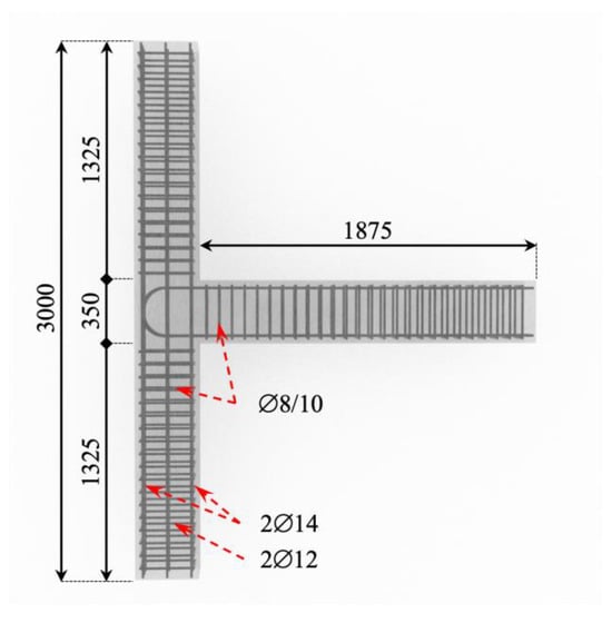
Figure 1.
Geometrical and reinforcement details of BCJ specimens.
2.2. Strengthening Scheme Details
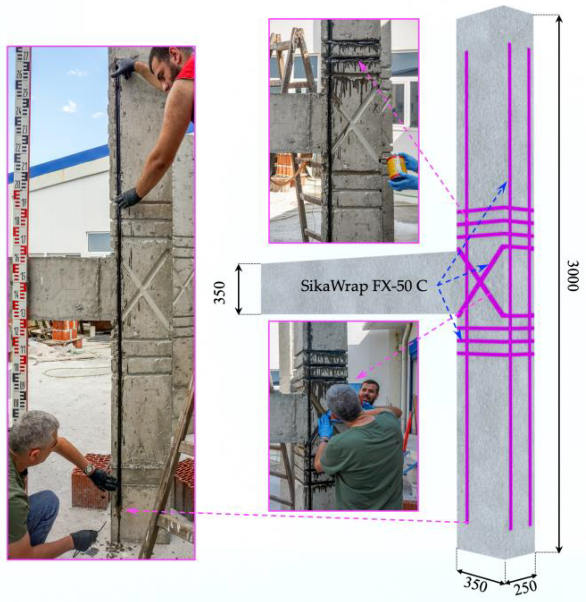
In this study, both specimens were retrofitted using an NSM technique with C-FRP ropes. The C-FRP ropes are commercially available through the Sika company under the designation SikaWrap FX-50 C (SIKA Hellas, Kryoneri, Greece). According to the manufacturer, the tensile strength of the dry fibers was equal to 4000 MPa, and their modulus of elasticity was 240 GPa. Furthermore, two types of epoxy resin from the same company were used. A low-viscosity epoxy resin was used to impregnate the C-FRP rope, which is commercially available under the designation Sikadur®-52. Additionally, Sika AnchorFix®-3+ was used to anchor the synthetic reinforcement. The installed NSM C-FRP ropes served as external longitudinal and transverse reinforcement for the column and shear reinforcement for the joint panel, enhancing their overall seismic behavior. Four C-FRP ropes were placed as longitudinal reinforcement along the column’s height to improve its flexural resistance, as illustrated in Figure 2. Three C-FRP ropes were incorporated as closed stirrups in the critical column–joint regions to enhance the column’s shear resistance. Additionally, two C-FRP ropes were diagonally applied on either side of the joint panel to improve the joint’s shear behavior, creating an X-shaped reinforcing scheme with four C-FRP ropes in total.

Figure 2.
Retrofitting scheme of BCJ specimens using NSM C-FRP ropes.
The implementation of the retrofitting scheme introduces a level of complexity and involves procedures that must be carefully executed, as outlined in the subsequent steps.
- Engraving and carving of U-shaped notches with a depth of 20–25 mm to apply the C-FRP ropes while assuring the integrity of conventional steel reinforcement of the specimens.
- Rounding the corners of the U-shaped notches where the C-FRP rope needs to be revolved to a minimum of a 20 mm radius.
- Clearing the accumulated dust from the intricate channels using compressed air.
- Impregnating the C-FRP rope with the low-viscosity epoxy resin Sikadur®-52 in accordance with the manufacturer’s technical data sheet.
- The impregnated C-FRP ropes were inserted and glided into the formed notches and the formation of their anchorage.
- The channel was filled with high-viscosity Sika AnchorFix®-3+ epoxy resin to improve the connection between the inserted materials and the rope’s anchorage.
2.3. Test Setup and Loading History
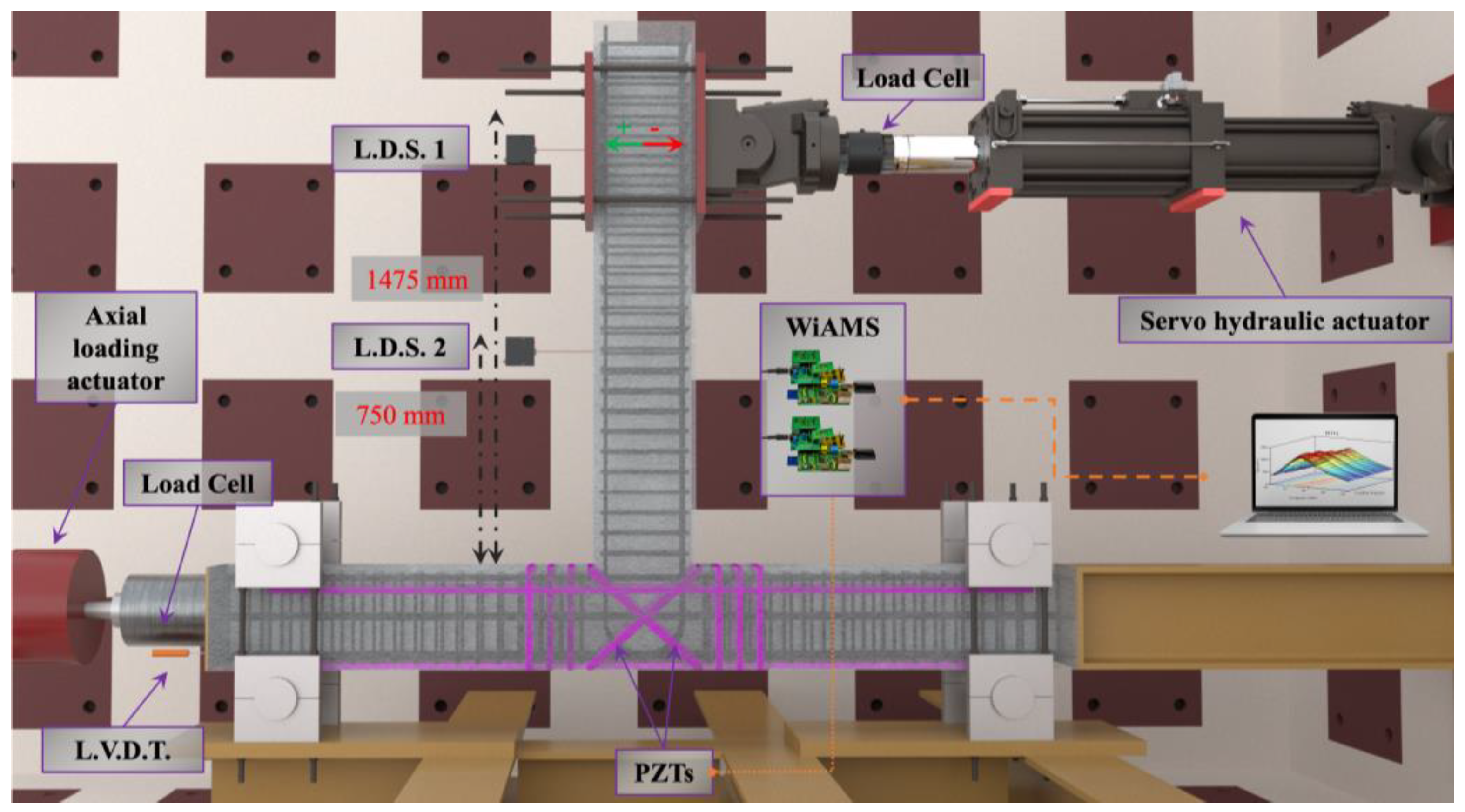
In this research, the BCJ specimens underwent a 90-degree rotation, with the column ultimately aligning horizontally while the beam transitioned to a vertical orientation. The column ends were pinned to the strong floor of the laboratory using a sandwich-type metal plate mechanism, enabling unrestricted rotation. Furthermore, a constant axial compressive load was applied in the column. The axial load ratio of the column was set to 5% of the maximum bearing compressive capacity. A servo-controlled hydraulic actuator imposed the cyclic loading sequence on the beam’s free end. Furthermore, the experimental configuration consisted of two Laser Displacement Sensors (LDS) employed to measure the displacement of the beam, as depicted in Figure 3. In addition, two Wireless impedance/Admittance Monitoring System (WiAMS) devices were utilized to capture the EMI responses of the PZT transducer.
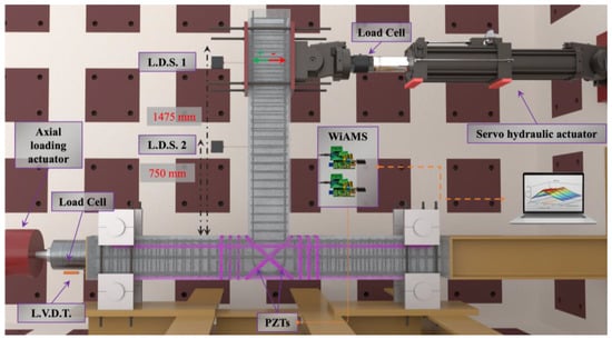
Figure 3.
Experimental setup of BCJ specimens.
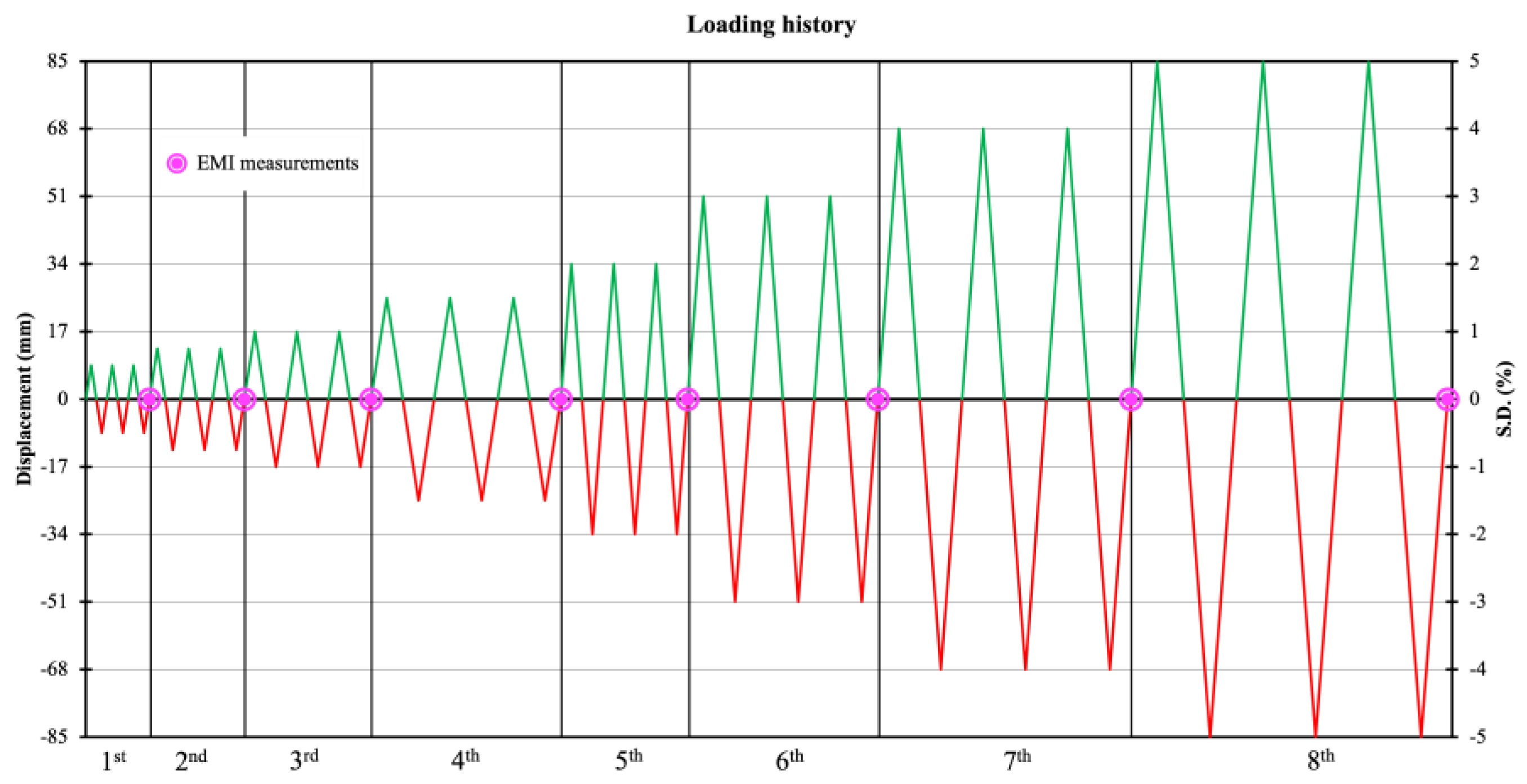
Establishing a loading history that comprehensively addresses the critical issues relating to the capacity of structural components and seismic demands is essential. This is crucial for effectively utilizing the results of quasi-static cyclic loading tests on structural elements to conduct a comprehensive seismic performance evaluation. Due to cumulative damage, the seismic capacity characteristics of structural elements diminish with each excursion in the inelastic range. Thus, this study selected a multi-cyclic loading sequence characterized by increasing displacement steps with significant inelastic excursions. Further, the consideration of cumulative damage resulting from multiple inelastic cycles has been proposed to be incorporated. Given the frequent occurrence of small amplitude cycle loadings in response to natural excitations, the adopted loading program consists of three complete loading cycles per step with identical deformations. It is worth noting that the adopted loading sequence results in significant drift values, which can be viewed as an assessment factor for behavior beyond conventional seismic design targets. The imposed deformations were calculated based on story drift (SD) percentages ranging from 0.5% to 5%. Accounting for the lever arm, the prescribed displacements for each increment were ±8.50 mm, ±12.75 mm, ±17.00 mm, ±25.50 mm, ±34.00 mm, ±51.00 mm, ±68.00 mm, and ±85.00 mm, as illustrated in Figure 4. Furthermore, at the end of each loading step, the EMI response of the PZT transducers was captured to monitor the performance of the retrofitting technique.
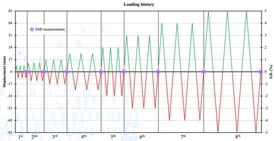
Figure 4.
Loading history and EMI measurements. The loading sequence consists of 8 steps, with each step encompassing three identical full loading cycles.
2.4. Implementation of the Retrofitting Technique Monitoring Framework
In this study, an EMI-based wireless SHM system was implemented. As mentioned, the EMI method exploits piezoelectric materials, such as PZTs, due to their inherent ability to generate surface electric charges when subjected to mechanical stress while simultaneously experiencing mechanical deformation in response to an electric field. Hence, any conversions observed in the electrical impedance of an attached PZT transducer stem from alterations in the mechanical impedance of the area under examination. The impedance response of the PZT is routinely captured to oversee the structural integrity of a structural component. Variations in the PZT’s impedance response measurements within a specified excitation frequency range suggest deterioration in the monitoring element’s structural integrity.
In the proposed methodology, PZT patches are epoxy attached to the C-FRP ropes to assess the performance of the employed retrofitting technique. The imposed beam’s deformation induces stress in the joint of the specimen. As the joint’s stress increases with each successive loading step, the formation of cracks is progressively intensified in the joint’s body due to the developed shear deformation. The C-FRP ropes undergo tensile strain as they restrain the crack width of the joint’s cracks. Thus, a PZT patch mounded in the C-FRP rope can capture the formation of cracks in the restrained concrete and the possible debonding of the synthetic reinforcement. Hence, two PZT transducers were epoxy-bonded in the outer surface of the C-FRP ropes, as illustrated in Figure 5. The PZT transducers were obtained from PI Ceramics and designated as PIC 151. The thickness of the transducers was 5 mm, and their length and width were 20 mm.
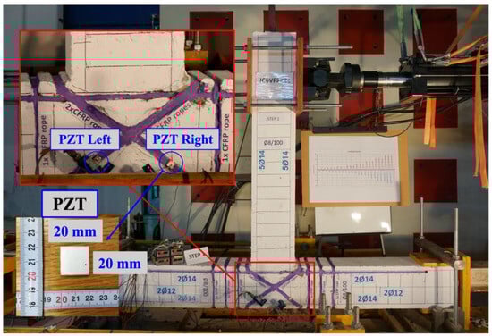
Figure 5.
Epoxy-bonded PZTs for SHM of BCJ specimens.
Furthermore, two WiAMS devices were employed to acquire the EMI response of the PZT transducers. The WiAMS device is a custom-made impedance analyzer initially developed by Providakis et al., and it has been widely utilized in numerous studies within the broader literature [67]. At this point, it is worth mentioning that in real-world cases/applications, ensuring long-term stability and reliability requires periodic calibration measurements. These measurements are typically performed on prototype PZTs using impedance analyzer stations that are either certified or calibrated by accredited laboratories.
Regular calibration is essential to account for any deviations in performance due to environmental factors, material degradation, or other operational stresses. By maintaining accurate and consistent calibration standards, the integrity of the monitoring system is upheld, thus ensuring precise measurements and reliable performance over extended periods of use.
Each WiAMS device captures the EMI response of a PZT patch in a predefined frequency range, which was set to 10–250 kHz with a resolution of 1 kHz. The acquired EMI responses of the PZTs were stored in an online database for post-processing. As mentioned above, the EMI measured identifies degradation of the mechanical impedance of the monitoring area through the alterations they cause in the EMI response of an attached PZT transducer. Hence, the EMI response of each PZT patch in the pristine condition of the specimens was captured and used as a baseline. Additionally, to assess the performance of the retrofitting technique, the EMI response of the attached PZT patches was captured after the end of each loading step.
The literature review revealed that the EMI method usually employs statistical indices to evaluate and/or quantify the variation in EMI responses induced by alteration of the monitoring area’s mechanical impedance. Thus, statistical indices, such as RMSD, can quantify the variation of the EMI response of a PZT patch between the pristine state and the examined state. The equation of the commonly used damage index RMSD is presented in Equation (1).
represents the absolute impedance value of the same PZT in the examined state D, denotes the absolute impedance value of the PZT in its pristine state, and represents the number of individual excitation frequencies.
The statistical index RMSD quantifies PZT’s EMI response variation across the recorded spectra. Thus, higher values of RMSD indicate alterations in the monitored area’s structural integrity. Although this approach has been proven efficient for damage identification in the published literature, there is a growing concern regarding the performance assessment of retrofitted RC elements. The diversity in the mechanical properties of the materials that coexist in retrofitted RC members increases the complexity of performance evaluation. Therefore, implementing machine learning techniques, such as hierarchical clustering, in retrofitting performance monitoring is gaining popularity in the literature.
This study employs the HCA to monitor the performance of retrofitted BCJs. Perera et al. describe the primary hypothesis for the PZT-enabled FRP debonding identification clustering approach, where the abrupt variation in the PZT response strongly indicates a decrease in structural integrity. Hierarchical clustering is an unsupervised machine learning algorithm that identifies a hierarchy of clusters based on the preselected metric distance. This study used the Cophenetic Correlation Coefficient (CCC) to determine the most suitable metric distance among Cityblock, Euclidean, Squared Euclidean, Minkowski, Chebychev, Cosine, and Correlation. Subsequently, the chosen metric’s dendrogram was utilized to visually represent the various clustering stages, thereby classifying the dissimilarity among the resulting groups. The equation for CCC is presented in Equation (2).
where is the distance according to the selected metric between each pair of observations, and , and is the cophenetic distances, illustrating the dissimilarity between groups at which the observations and initially merge into the same cluster.
In this study, each measurement was considered an individual cluster by HCA. The similarity degree of each cluster was calculated according to the chosen metric distance. Then, the observations with the highest degree of similarity were combined to form a new cluster. The aforementioned procedure was reiterated through an iterative process until all observations were consolidated into a single cluster with an agglomeration hierarchy. Subsequently, a dendrogram was utilized to provide a visual representation of the various stages of clustering, enabling classification of the dissimilarity among the formed groups.
3. Results
3.1. Mechanical Behavior of Retrofitted BCJs
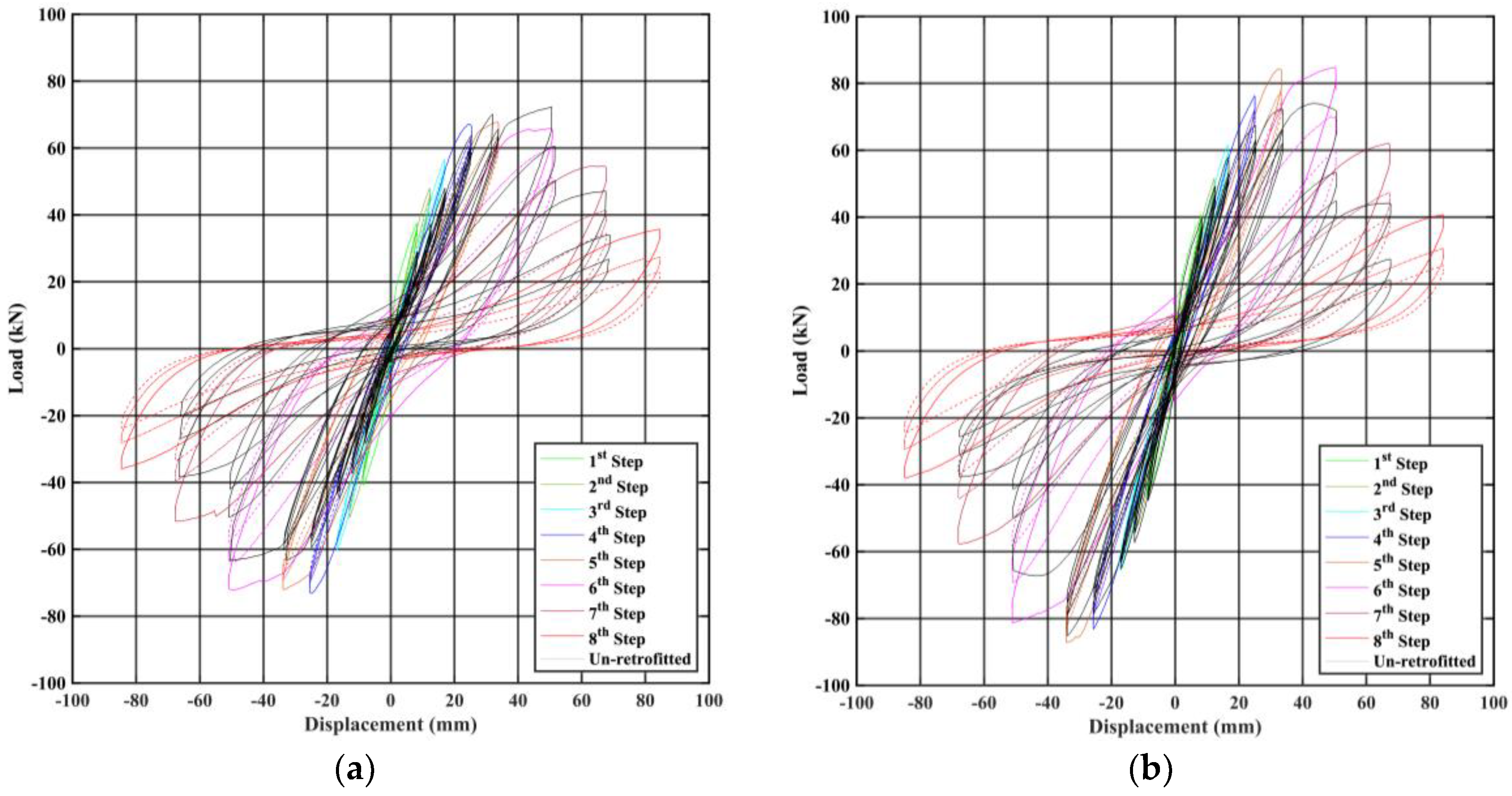
As mentioned, both specimens were retrofitted with C-FRP ropes due to insufficient conventional reinforcement. In Figure 6, the mechanical behavior of the reference and the examined BCJs is illustrated. The horizontal axis represents the imposed displacement, while the vertical axis represents the corresponding load. Both specimens displayed the capability to preserve their structural integrity up to the eighth loading step, representing a story drift of 5%. Contrarily, unretrofitted specimens, published by Karayannis et al., with identical geometrical properties and reinforcing details, subject to the same testing protocol, experienced a brittle failure on the seventh loading step, resulting in a 4% story drift [5]. Specimen 1’s mechanical response peaks at around −70 kN during the first negative cycle of the fourth, fifth, and sixth steps and gradually degrades in the following cycles, reaching −34 kN in the first negative cycle of the 8th step. Although the specimen was reinforced symmetrically, there is a noticeable disparity of 5 kN in their positive and negative responses. This difference is likely attributable to the pattern of the cracks formed in the joint panel, which is evident in the unretrofitted specimen also. Furthermore, there is a progressive reduction in the bearing capacity of Specimen 1 as the repeated deformation cycles continue beyond the sixth loading step, indicating that significant damage occurred at these steps.
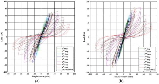
Figure 6.
Comparative experimental mechanical behavior of BCJs with the unretrofitted specimen under cycle loading. (a) Specimen 1 and (b) Specimen 2.
Additionally, as seen in Figure 6b, the mechanical response peaks of Specimen 2 reach 83 kN during the first positive cycle of the sixth step and gradually degrade in the following cycles, reaching 40 kN in the first negative cycle of the eighth step. Similarly, as with Specimen 1, there is a clear difference between their positive and negative responses and a progressive reduction in its bearing capacity as the repeated deformation cycles continue beyond the sixth loading step. The retrofitting technique has notably improved the specimens’ ductility and overall post-peak behavior while exhibiting a slight increase in its load-bearing capacity.
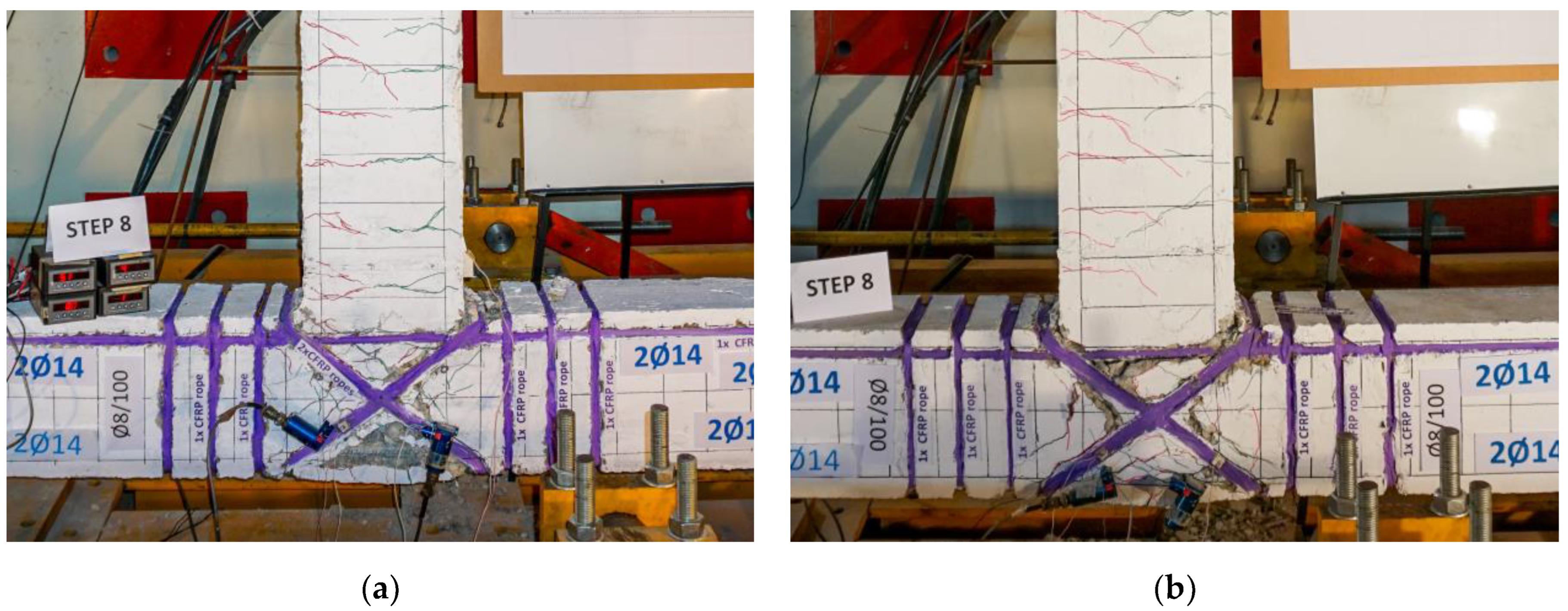
Furthermore, Figure 7a,b illustrate the cracking patterns formed at the end of the loading sequence in the joint panels of Specimen 1 and Specimen 2, respectively. The application of C-FRP ropes restrains the width of the cracks and enhances the seismic capacity of both specimens. Despite the lower longitudinal reinforcement of Specimen 1’s beam, it exhibited greater severe damage than Specimen 2. However, both specimens demonstrate significantly improved seismic performance compared to unreinforced BCJs regarding ductility and the severity of BCJs’ panel cracking.
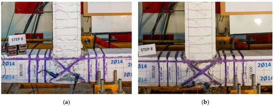
Figure 7.
Comparison of the BCJ panels’ cracking pattern at the end of the loading sequence. (a) Specimen 1 and (b) Specimen 2.
3.2. Monitoring of Retrofitted BCJs
As mentioned above, to monitor the retrofitting technique’s performance, a PZT transducer was attached to each C-FRP rope, and their EMI responses were captured at the end of each loading step. Sequentially, the alterations of the EMI responses were evaluated through the statistical damage index RMSD and HCA. The results of those analyses are discussed in this subsection.
3.2.1. Statistical Damage Index RMSD
Figure 8 presents the RMSD values of the epoxy-bonded PZT patches of Specimen 1. The PZT Left exhibits steady growth from 4.5% at the third loading step to 13.9% at the end of the seventh loading step, which is owed to the extensive crack formation in the patch’s vicinity, resulting in the activation of the C-FRP rope to mitigate the cracking growing rate. During the eighth and final loading step, the joint panel displays significant cracking, as reflected by the sharp increase in the RMSD values of PZT Left to 18.3%.
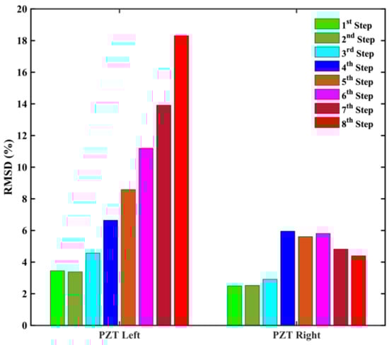
Figure 8.
RMSD values of epoxy-bonded PZT patches of Specimen 1.
In contrast, the RMSD values of PZT Right increase up to the fourth loading step, reaching 6%, and remain unchanged up to the sixth loading step. In the final loading steps, the RMSD values of PZT Right show slight decreases. Although PZTs were placed in C-FRP ropes symmetrically, they exhibited different RMSD results due to the unsymmetrical cracking pattern. Furthermore, the BCJ’s hysterical performance was unsymmetrical, as discussed in Section 3.1.
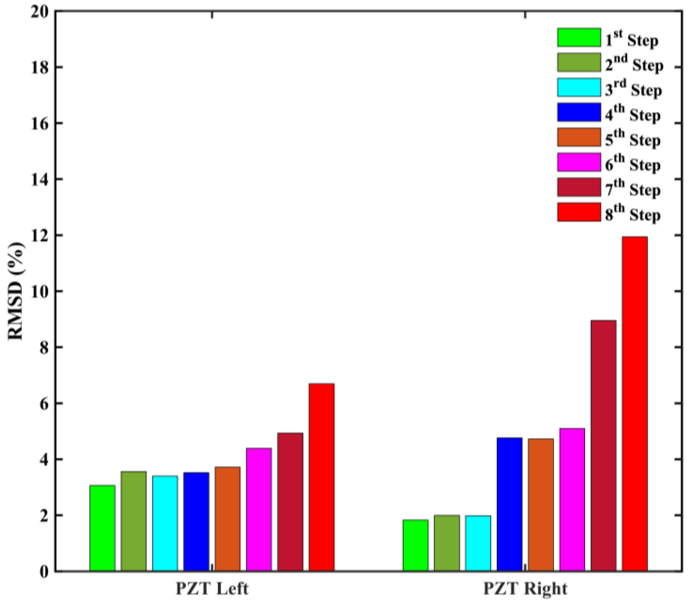
Similarly, Figure 9 presents the RMSD values of the epoxy-bonded PZT patches of Specimen 2. The RMSD values of both patches exhibit an upward trend throughout the loading sequence. The RMSD values of PZT Left increase slowly up to the fifth loading step, reaching 3.7%. Subsequently, the RMSD values of PZT Left increase more steeply, reaching up to 6.7% at the end of the loading sequence. The RMSD values of the PZT Right indicate a notable increase in its RMSD volume ratio at the fourth loading step, reaching 4.7%, which remains relatively stable up to the sixth loading step. This can be attributed to the extensive cracking propagation in the vicinity of the patch and the activation of the C-FRP rope, contributing to mitigating shear deformations and thereby enhancing the resistance of the retrofitted joint. Eventually, the RMSD values of PZT Right rise to approximately 9% at the seventh loading step and 12% at the eighth loading step, reflecting the development of stresses on the rope as it strives to withstand the extended cracking of the joint. This observation aligns with the specimen’s mechanical response and the dense mesh of cracks that formed in the joint panel.
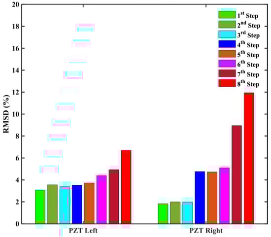
Figure 9.
RMSD values of epoxy-bonded PZT patches of Specimen 2.
The RMSD values of the PZT patches attached to the C-FRP ropes align with the mechanical response and the cracking pattern formed in both specimens’ joint panels. Therefore, PZT patches can provide insightful information regarding the performance of the retrofitting technique. The proposed monitoring approach detects micro-fracture development within the C-FRP rope or the adjacent concrete through the exceptional sensitivity of PZT transducers. Consequently, the PZT transducers are suitable for continuous monitoring of retrofitted BCJs.
3.2.2. Hierarchical Clustering Approach
This study further explores the implementation of the HCA as an additional method for assessing the performance of retrofitted BCJs. The primary rationale for integrating HCA in this study stemmed from the recognition that conventional damage indices, such as RMSD, evaluate the performance of retrofitted BCJs solely based on scalar values. Frequently, it is noted that similar damage index values may indicate varying structural conditions, leading to potential inaccuracies in alerts. Therefore, the HCA was applied as a supplementary tool for co-evaluating the statistical analysis results.
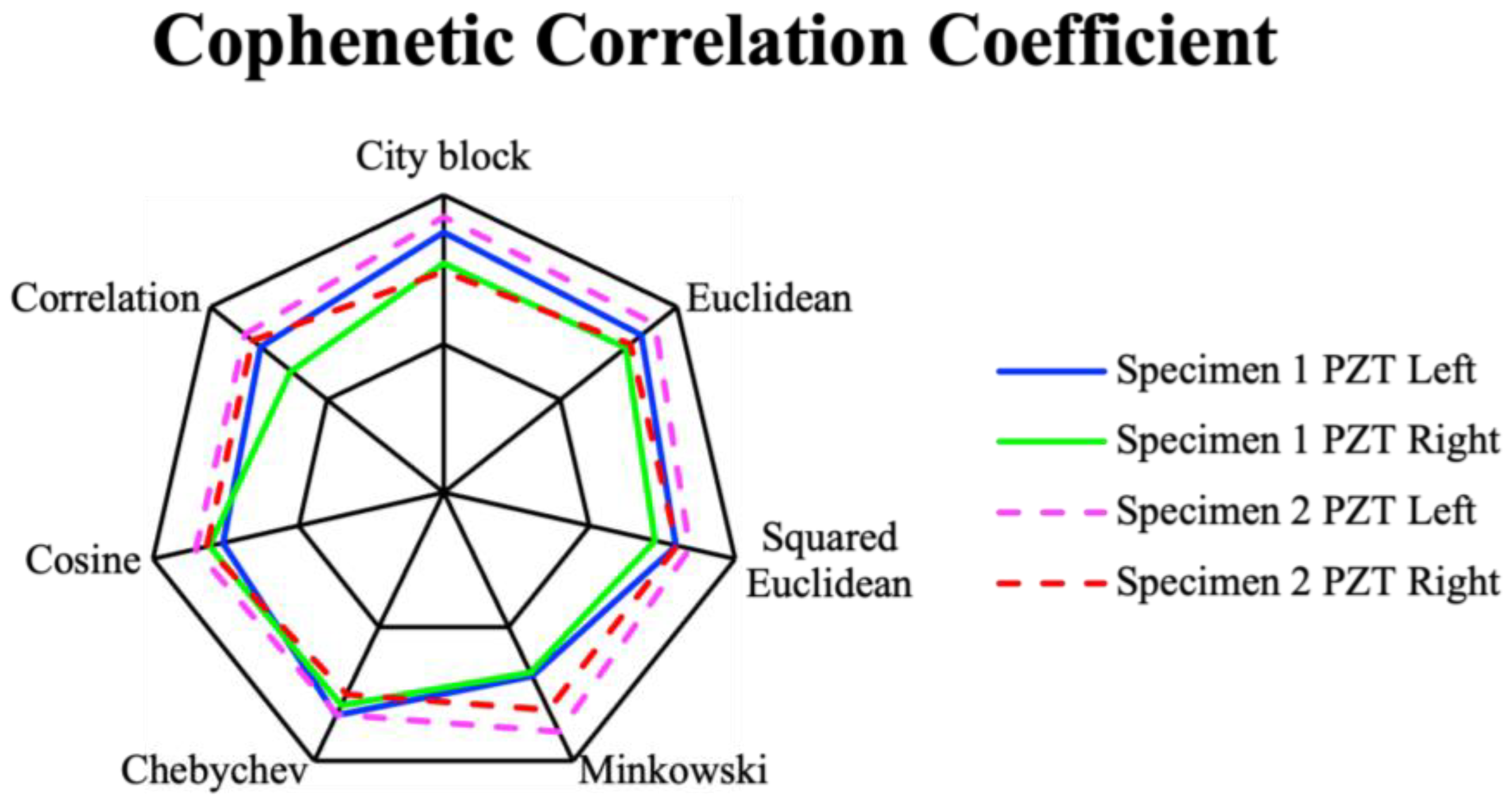
Figure 10 depicts the CCC values from all of the PZTs across the various metric distances examined in this study. The CCC quantifies the degree to which a dendrogram accurately maintains the initial pairwise distances between unmodeled data points and represents how accurately the dendrogram represents the differences between observations. Perera et al. suggest that CCC values exceeding 0.7 indicate a strong fit for a cluster. Thus, it is essential to highlight that every PZT demonstrates CCC values exceeding 0.7 for all of the investigated metric distances. The city block metric exhibits notably higher average CCC values and is, therefore, selected for further analysis.
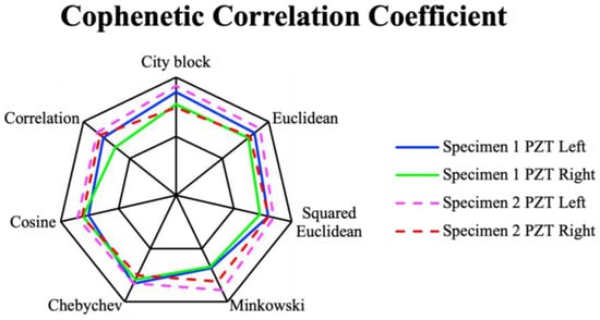
Figure 10.
The CCC values of utilized metric distances.
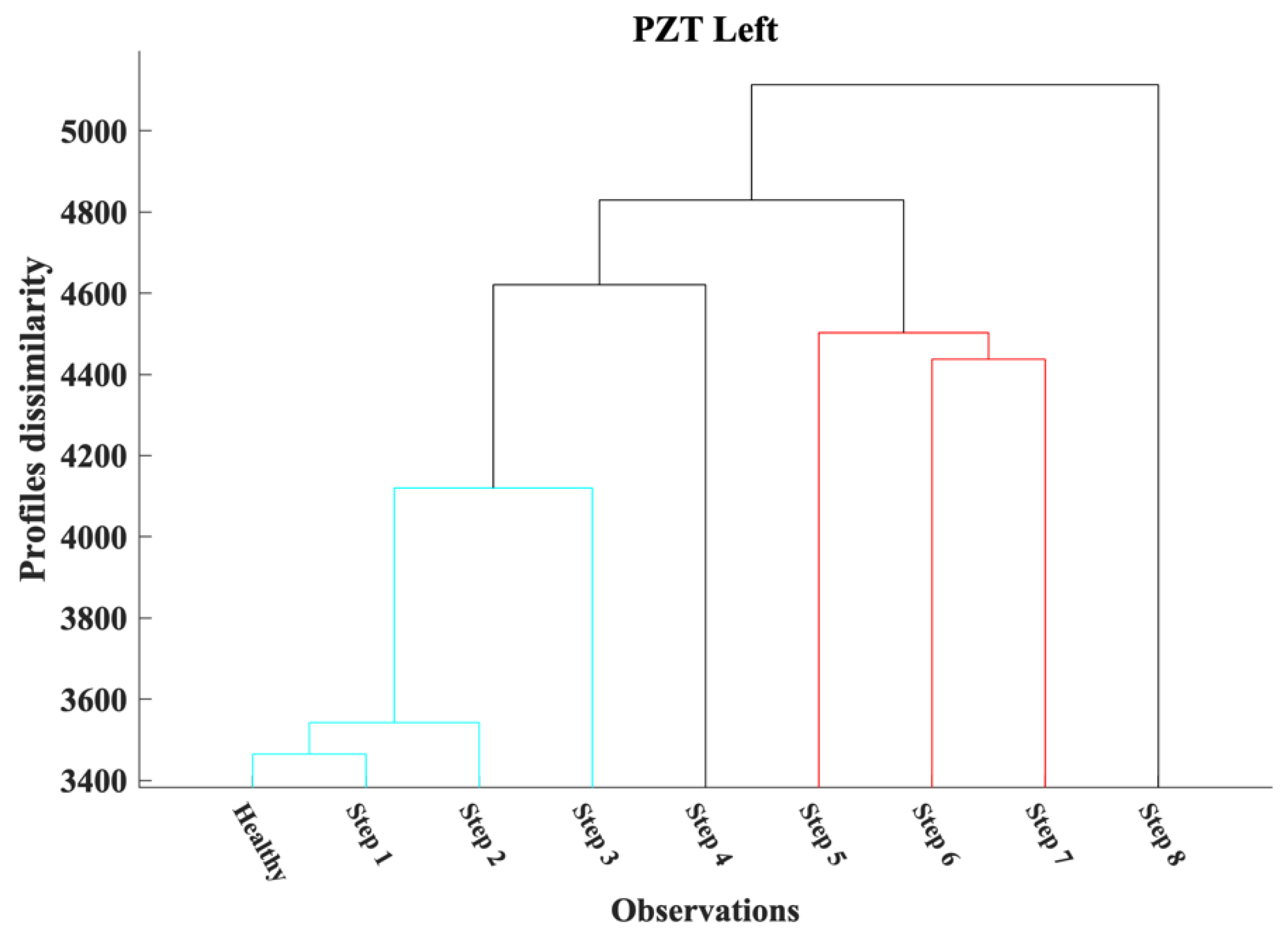
The HCA results are illustrated through dendrograms, which reflect the multilevel hierarchy of the EMI responses of each PZT transducer. The multilevel hierarchy results from the degree of dissimilarity between the EMI responses captured at the end of each loading step. Figure 11 depicts the dendrogram of PZT Left, where HCA separates its EMI responses into two main clusters. The first cluster contains the EMI responses of PZT Left in the healthy condition and up to the third loading step. The EMI measurements captured at the end of the fifth, sixth, and seventh loading steps form the second cluster. The EMI response of the fourth loading step appears to be in a transitional structural state due to the activation of the C-FRP rope to restrain the growing cracks. Additionally, the eighth loading step observation was distinguished from the rest due to the formation of severe damage in the BCJ panel. The HCA promptly identified stress development within the C-FRP rope, which benefits the mechanical response of the retrofitted BCJ. Furthermore, HCA distinguishes the performance of C-FRP into four states based on the variations in EMI responses of PZT Left.
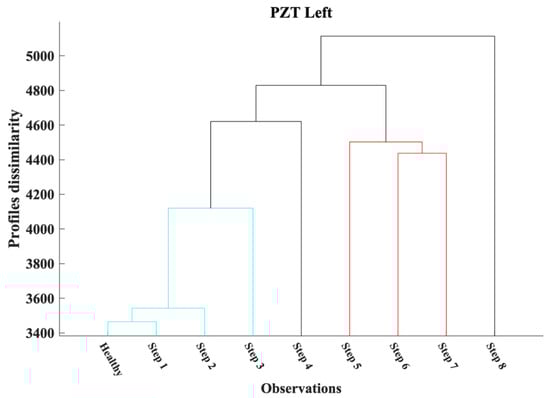
Figure 11.
The HCA results for PZT Left of Specimen 1.
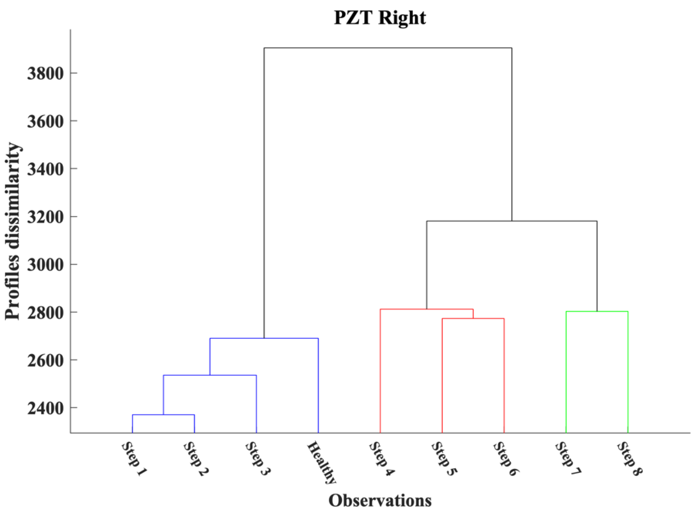
HCA also separates the EMI responses of PZT Right into three clusters, as illustrated in Figure 12. The first cluster contains the EMI responses of PZT Right in the healthy condition and up to the end of the third loading step. The fourth, fifth, and sixth loading step observations were placed on the second cluster. During those loading steps, the C-FRP rope successfully restrains the cracks formed within the BCJ body. The rest of the EMI responses form the third cluster, where the bearing capacity of the BCJ degrades significantly. Although the RMSD values of PZT Left were notably higher than the RMSD values of PZT Right, HCA promptly identified the severe damage of the BCJ panel and the excessive stress developed in the C-FRP rope to mitigate the crack’s further growth from both PZT transducers.
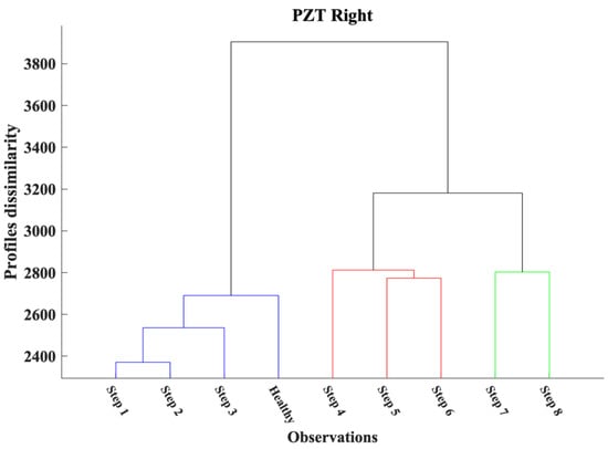
Figure 12.
The HCA results for PZT Right of Specimen 1.
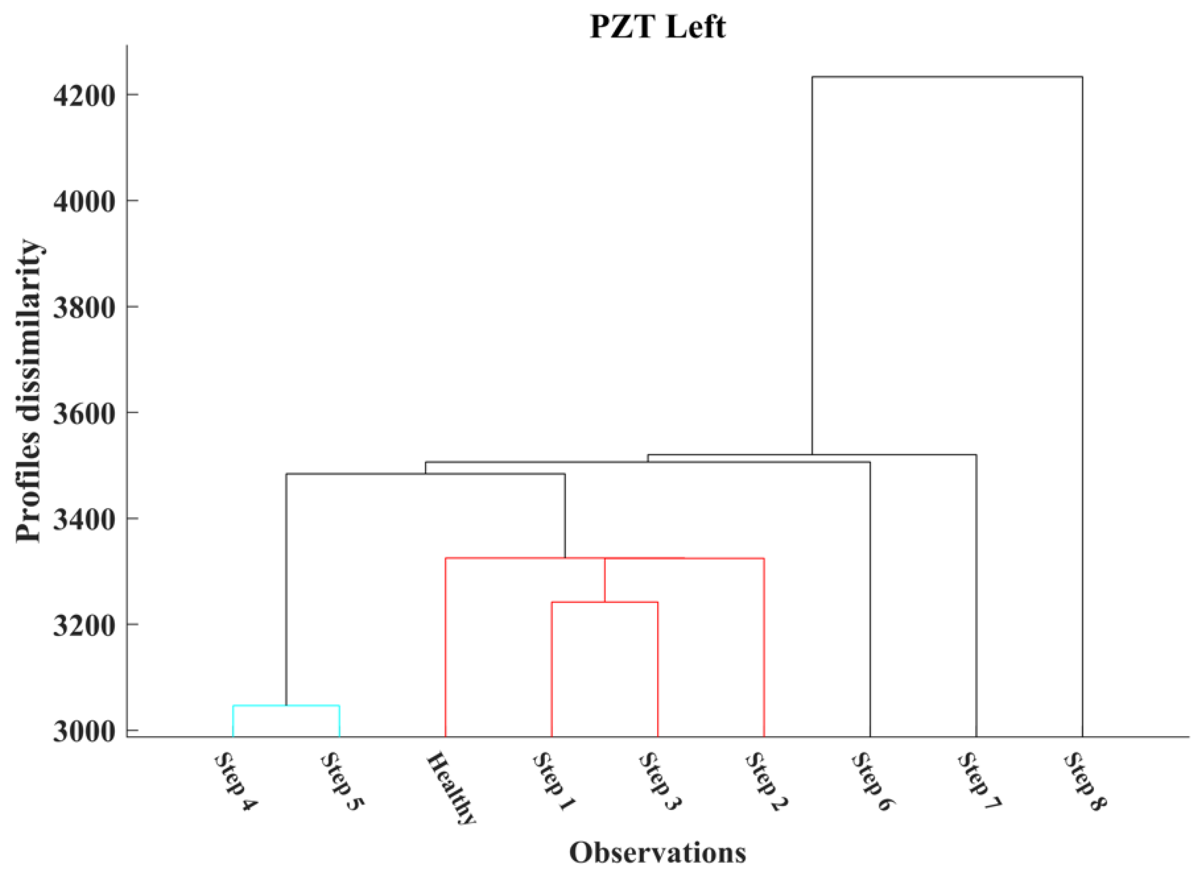
Furthermore, Figure 13 and Figure 14 present the dendrograms of PZT Left and PZT Right attached to the C-FRP ropes of Specimen 2, respectively. The HCA separates the EMI responses of PZT Left into two clusters and three additional measurements. The HCA forms two clusters and three additional measurements, as illustrated in Figure 13. The first cluster contains the EMI responses of PZT Left in the healthy condition up to the end of the third loading step, while the second cluster is formed from the EMI responses of the fourth and fifth loading steps. As mentioned, the bearing capacity of Specimen 2 decreases significantly after the sixth loading step, as depicted in Figure 6b. The HCA identifies this decrease from the corresponding significant increase in the dissimilarity degree of the EMI responses in the sixth, seventh, and eighth loading steps.
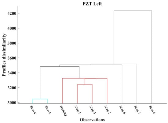
Figure 13.
The HCA results for PZT Left of Specimen 2.
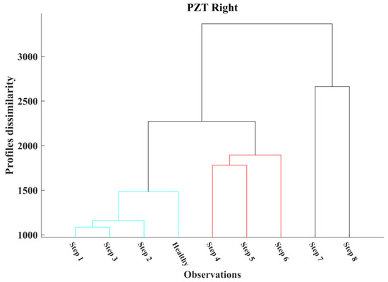
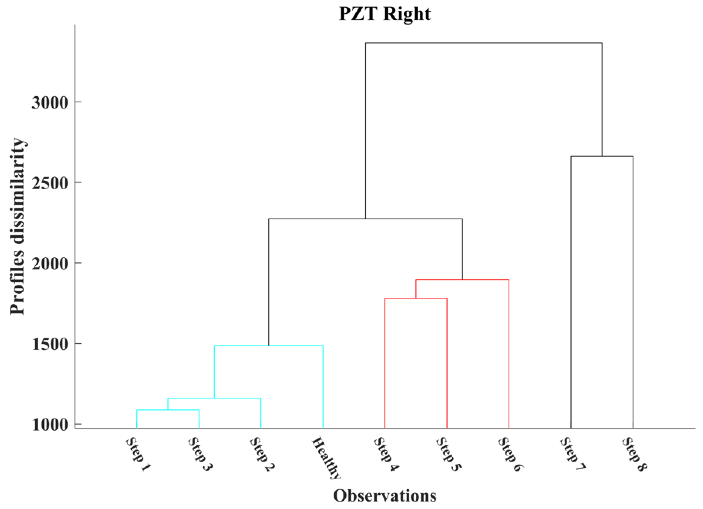
Figure 14.
The HCA results for PZT Right of Specimen 2.
Additionally, Figure 14 presents the dendrogram of PZT Right, where three clusters are observed. The first cluster contains the EMI responses of PZT Left in the healthy condition up to the end of the third loading step, where only small-width cracks were formed in Specimen 2. The second cluster was formed from the EMI responses of the fourth, fifth, and sixth loading steps, where Specimen 2 reached its maximum bearing capacity. Finally, the third cluster contains the EMI responses of the seventh and eighth loading steps, where Specimen 2 exhibits severe damage.
4. Discussion
In this experimental work, the application of a C-FRP retrofitting scheme in RC BCJs demonstrated promising and essential outcomes. In particular, the C-FRP implementation enhanced the mechanical performance of the joints (post-elastic behavior), improving the deformation capacity and thus elevating the ductility. Furthermore, the higher ductility is essential for absorbing and dissipating energy effectively, especially when the RC member is subjected to dynamic or seismic loading conditions.
In addition, the proposed retrofitting scheme demonstrated its effectiveness in controlling and limiting crack propagation. By restraining the formation and development of cracks, the scheme assisted in maintaining the BCJs’ structural integrity, reducing the risk of brittle failure.
However, the assessment of retrofitted RC members’ performance poses a complex challenge due to the multitude of underlying parameters affecting it. While commonly utilized statistical damage indices offer valuable insights, they are inadequate to fulfill this task independently. The investigation into combining the scalar damage index RMSD with the HCA has yielded auspicious results. Although RMSD values of both specimens of PZT exhibit an upward pattern, establishing a trigger-alerting value is still an open challenge. Under certain assumptions, this can be due to the non-uniform crack patterns of BCJs.
Hence, HCA was employed as an additional post-processing technique to address this potential limitation. The findings indicate that the city block metric demonstrates significantly higher average CCC values than the other metrics utilized in this analysis. Further, HCA successfully categorized the EMI measurements of all PZTs into three classes of structural performance. Therefore, the findings of this study indicate that HCA can consistently detect the degradation of structural integrity in retrofitted BCJs. The conclusions drawn from this study on HCA align with the findings presented by Perera et al. [14,48], despite their application to a significantly more intricate structural component.
Nevertheless, leveraging the advantages of the combined RMSD and HCA led to more favorable outcomes. The HCA promptly recognizes the deterioration of structural integrity near the PZT, and the RMSD, thanks to its scalar nature, provides a quantitative measure of it. Therefore, the proposed approach offers a thorough and dependable evaluation of retrofitting performance, yielding a more comprehensive assessment.
5. Conclusions
This study investigates a newly developed strengthening method for RC BCJs employing C-FRP ropes. Additionally, the C-FRP retrofitting scheme demonstrated its effectiveness in controlling and limiting crack propagation. By restraining the formation and expansion of cracks, the retrofit helped maintain the structural integrity of the RC BCJs, thereby enhancing strength in critical stress regions and reducing the risk of brittle failure. Moreover, crack mitigation contributes to the extension of service life and the durability of the retrofitted joints.
Furthermore, an EMI-based, PZT-enabled, novel approach was introduced to monitor the effectiveness of the retrofitting technique. The results of this study indicate that the proposed method effectively identifies early-stage damage in both specimens, fulfilling the objective of promptly diagnosis and providing crucial information for crisis response and management. Additionally, the results validate that the RMSD scalar damage index effectively monitors the deterioration of structural integrity in the retrofitted BCJs by quantifying the variation in PZT EMI responses. Nevertheless, HCA appears to be an advantageous supplementary method for monitoring the performance state of the C-FRP retrofitting technique.
In summary, the aforementioned points underscore the argument that integrating the suggested retrofitting techniques using C-FRP ropes and the proposed EMI-based and PZT-enabled monitoring system for RC structures meets the requirements for resilience, thereby supporting the development of resilient societies. However, the proposed approach is still limited to categorizing structural performance classes and serving as an early warning system. While the current study does not cover this topic, future research could explore the integration of regression techniques to offer valuable insights into retrofitting design and assessment.
Author Contributions
Conceptualization, G.M.S., C.G.K. and C.E.C.; methodology, G.M.S., M.C.N., C.G.K. and C.E.C.; software, G.M.S. and N.A.P.; validation, G.M.S., M.C.N., N.A.P. and E.G.; formal analysis G.M.S., M.C.N. and N.A.P.; investigation, G.M.S., M.C.N. and E.G.; data curation, G.M.S., N.A.P. and E.G.; writing—original draft preparation, G.M.S. and N.A.P.; writing—review and editing, G.M.S., M.C.N. and C.E.C.; visualization, G.M.S. and M.C.N.; supervision, M.C.N., C.G.K. and C.E.C. All authors have read and agreed to the published version of the manuscript.
Funding
This research received no external funding.
Institutional Review Board Statement
Not applicable.
Informed Consent Statement
Not applicable.
Data Availability Statement
The data presented in this study are available upon request from the corresponding author.
Acknowledgments
The authors wish to thank SIKA Hellas for supplying the C-FRP reinforcements and filling materials (impregnating resin and epoxy paste), including, in particular, Nikos Anagnostopoulos for his advice and support in the strengthening application of the tested beams.
Conflicts of Interest
The authors declare no conflicts of interest.
References
- De Luca, F.; Woods, G.E.D.; Galasso, C.; D’Ayala, D. RC Infilled Building Performance against the Evidence of the 2016 EEFIT Central Italy Post-Earthquake Reconnaissance Mission: Empirical Fragilities and Comparison with the FAST Method. Bull. Earthq. Eng. 2018, 16, 2943–2969. [Google Scholar] [CrossRef]
- Eslami, A.; Ronagh, H.R. Effect of FRP Wrapping in Seismic Performance of RC Buildings with and without Special Detailing—A Case Study. Compos. Part B Eng. 2013, 45, 1265–1274. [Google Scholar] [CrossRef]
- Tsonos, A.D.G.; Kalogeropoulos, G.I.; Iakovidis, P.E.; Konstantinidis, D. Seismic Retrofitting of Pre-1970 RC Bridge Columns Using Innovative Jackets. IJStructE 2017, 8, 133. [Google Scholar] [CrossRef]
- Tsonos Alexandros-Dimitrios, G. Model for the Evaluation of the Beam-Column Joint Ultimate Strength -a More Simplified Version. Earthq. Struct. 2019, 16, 141–148. [Google Scholar] [CrossRef]
- Karayannis, C.G.; Golias, E.; Naoum, M.C.; Chalioris, C.E. Efficacy and Damage Diagnosis of Reinforced Concrete Columns and Joints Strengthened with FRP Ropes Using Piezoelectric Transducers. Sensors 2022, 22, 8294. [Google Scholar] [CrossRef]
- Kharwar, K.L.; Maurya, K.K.; Rawat, A. Retrofitting Techniques of Damaged Concrete Structure for Environment Concern: A Review. Mater. Today Proc. 2022, 65, 1161–1168. [Google Scholar] [CrossRef]
- Tsonos, A.-D.; Kalogeropoulos, G.; Iakovidis, P.; Bezas, M.-Z.; Koumtzis, M. Seismic Performance of RC Beam–Column Joints Designed According to Older and Modern Codes: An Attempt to Reduce Conventional Reinforcement Using Steel Fiber Reinforced Concrete. Fibers 2021, 9, 45. [Google Scholar] [CrossRef]
- Triantafyllou, G.G.; Rousakis, T.C.; Karabinis, A.I. Corroded RC Beams Patch Repaired and Strengthened in Flexure with Fiber-Reinforced Polymer Laminates. Compos. Part B Eng. 2017, 112, 125–136. [Google Scholar] [CrossRef]
- Perera, R.; Huerta, M.C.; Baena, M.; Barris, C. Analysis of FRP-Strengthened Reinforced Concrete Beams Using Electromechanical Impedance Technique and Digital Image Correlation System. Sensors 2023, 23, 8933. [Google Scholar] [CrossRef]
- Wang, H.; Li, C.; Song, S.; Wang, Y.; Meng, Q.; Li, F. Flexural Performance of Cracked Reinforced Concrete Beams Strengthened with Prestressed CFRP Sheets under Repeated Loads. Buildings 2023, 13, 2115. [Google Scholar] [CrossRef]
- Fanaradelli, T.; Rousakis, T.; Karabinis, A. Reinforced Concrete Columns of Square and Rectangular Section, Confined with FRP—Prediction of Stress and Strain at Failure. Compos. Part B Eng. 2019, 174, 107046. [Google Scholar] [CrossRef]
- Rousakis, T.C. Resilience Reserve of RC Columns Externaly Confined with Composite Rope or FRP Sheet under Seismic Overloads. In Proceedings of the International Conference on FRP Composites in Civil Engineering, CICE 2016, Hong Kong, China, 14–16 December 2016; pp. 1033–1038. [Google Scholar]
- Chen, H.; Xu, B.; Zhou, T.; Mo, Y.-L. Debonding Detection for Rectangular CFST Using Surface Wave Measurement: Test and Multi-Physical Fields Numerical Simulation. Mech. Syst. Signal Process. 2019, 117, 238–254. [Google Scholar] [CrossRef]
- Baena, M.; Jahani, Y.; Torres, L.; Barris, C.; Perera, R. Flexural Performance and End Debonding Prediction of NSM Carbon FRP-Strengthened Reinforced Concrete Beams under Different Service Temperatures. Polymers 2023, 15, 851. [Google Scholar] [CrossRef] [PubMed]
- Sevillano, E.; Sun, R.; Perera, R.; Arteaga, A.; De Diego, A.; Cisneros, D. Comparison of PZT and FBG Sensing Technologies for Debonding Detection on Reinforced Concrete Beams Strengthened with External CFRP Strips Subjected to Bending Loads. Mater. Constr. 2016, 66, e088. [Google Scholar] [CrossRef]
- Benavent, A.; Castro, E.; Gallego, A. Evaluation of Low-Cycle Fatigue Damage in RC Exterior Beam-Column Subassemblages by Acoustic Emission. Constr. Build. Mater. 2010, 24, 1830–1842. [Google Scholar] [CrossRef]
- Ai, D.; Du, L.; Li, H.; Zhu, H. Corrosion Damage Identification for Reinforced Concrete Beam Using Embedded Piezoelectric Transducer: Numerical Simulation. Measurement 2022, 192, 110925. [Google Scholar] [CrossRef]
- Yan, S.; Ma, H.; Li, P.; Song, G.; Wu, J. Development and Application of a Structural Health Monitoring System Based on Wireless Smart Aggregates. Sensors 2017, 17, 1641. [Google Scholar] [CrossRef]
- Naoum, M.C.; Sapidis, G.M.; Papadopoulos, N.A.; Voutetaki, M.E. An Electromechanical Impedance-Based Application of Realtime Monitoring for the Load-Induced Flexural Stress and Damage in Fiber-Reinforced Concrete. Fibers 2023, 11, 34. [Google Scholar] [CrossRef]
- Kocherla, A.; Subramaniam, K.V.L. Embedded Smart PZT-Based Sensor for Internal Damage Detection in Concrete under Applied Compression. Measurement 2020, 163, 108018. [Google Scholar] [CrossRef]
- Bhalla, S.; Yang, Y.W.; Xu, J.F.; Soh, C.K. Damage Quantification Using EMI Technique. In Smart Materials in Structural Health Monitoring, Control and Biomechanics; Advanced Topics in Science and Technology in China; Springer: Berlin/Heidelberg, Germany, 2012; pp. 129–186. ISBN 978-3-642-24462-9. [Google Scholar]
- Ai, D.; Luo, H.; Wang, C.; Zhu, H. Monitoring of the Load-Induced RC Beam Structural Tension/Compression Stress and Damage Using Piezoelectric Transducers. Eng. Struct. 2018, 154, 38–51. [Google Scholar] [CrossRef]
- Ai, D.; Mo, F.; Han, Y.; Wen, J. Automated Identification of Compressive Stress and Damage in Concrete Specimen Using Convolutional Neural Network Learned Electromechanical Admittance. Eng. Struct. 2022, 259, 114176. [Google Scholar] [CrossRef]
- Jiao, P.; Egbe, K.-J.I.; Xie, Y.; Matin Nazar, A.; Alavi, A.H. Piezoelectric Sensing Techniques in Structural Health Monitoring: A State-of-the-Art Review. Sensors 2020, 20, 3730. [Google Scholar] [CrossRef] [PubMed]
- Pham, Q.-Q.; Dang, N.-L.; Kim, J.-T. Smart PZT-Embedded Sensors for Impedance Monitoring in Prestressed Concrete Anchorage. Sensors 2021, 21, 7918. [Google Scholar] [CrossRef] [PubMed]
- Hire, J.H.; Hosseini, S.; Moradi, F. Optimum PZT Patch Size for Corrosion Detection in Reinforced Concrete Using the Electromechanical Impedance Technique. Sensors 2021, 21, 3903. [Google Scholar] [CrossRef] [PubMed]
- Morwal, T.; Bansal, T.; Azam, A.; Talakokula, V. Monitoring Chloride-Induced Corrosion in Metallic and Reinforced/Prestressed Concrete Structures Using Piezo Sensors-Based Electro-Mechanical Impedance Technique: A Review. Measurement 2023, 218, 113102. [Google Scholar] [CrossRef]
- Talakokula, V.; Bhalla, S.; Gupta, A. Corrosion Assessment of Reinforced Concrete Structures Based on Equivalent Structural Parameters Using Electro-Mechanical Impedance Technique. J. Intell. Mater. Syst. Struct. 2014, 25, 484–500. [Google Scholar] [CrossRef]
- Ai, D.; Yang, Z.; Li, H.; Zhu, H. Heating-Time Effect on Electromechanical Admittance of Surface-Bonded PZT Sensor for Concrete Structural Monitoring. Measurement 2021, 184, 109992. [Google Scholar] [CrossRef]
- Perera, R.; Torres, L.; Díaz, F.J.; Barris, C.; Baena, M. Analysis of the Impact of Sustained Load and Temperature on the Performance of the Electromechanical Impedance Technique through Multilevel Machine Learning and FBG Sensors. Sensors 2021, 21, 5755. [Google Scholar] [CrossRef]
- Ai, D.; Zhu, H.; Luo, H. Sensitivity of Embedded Active PZT Sensor for Concrete Structural Impact Damage Detection. Constr. Build. Mater. 2016, 111, 348–357. [Google Scholar] [CrossRef]
- Tseng, K.K.; Wang, L. Smart Piezoelectric Transducers for in Situ Health Monitoring of Concrete. Smart Mater. Struct. 2004, 13, 1017–1024. [Google Scholar] [CrossRef]
- Ai, D.; Cheng, J. A Deep Learning Approach for Electromechanical Impedance Based Concrete Structural Damage Quantification Using Two-Dimensional Convolutional Neural Network. Mech. Syst. Signal Process. 2023, 183, 109634. [Google Scholar] [CrossRef]
- Guo, B.; Chen, D.; Huo, L.; Song, G. Monitoring of Grouting Compactness in Tendon Duct Using Multi-Sensing Electro-Mechanical Impedance Method. Appl. Sci. 2020, 10, 2018. [Google Scholar] [CrossRef]
- Jiang, T.; Kong, Q.; Wang, W.; Huo, L.; Song, G. Monitoring of Grouting Compactness in a Post-Tensioning Tendon Duct Using Piezoceramic Transducers. Sensors 2016, 16, 1343. [Google Scholar] [CrossRef] [PubMed]
- Lee, J.-C.; Lee, C.-J. Electro-Mechanical Impedance Technique for Assessing the Setting Time of Steel-Fiber-Reinforced Mortar Using Embedded Piezoelectric Sensor. Appl. Sci. 2022, 12, 3964. [Google Scholar] [CrossRef]
- Zhang, C.; Panda, G.P.; Yan, Q.; Zhang, W.; Vipulanandan, C.; Song, G. Monitoring Early-Age Hydration and Setting of Portland Cement Paste by Piezoelectric Transducers via Electromechanical Impedance Method. Constr. Build. Mater. 2020, 258, 120348. [Google Scholar] [CrossRef]
- Naoum, M.C.; Papadopoulos, N.A.; Voutetaki, M.E.; Chalioris, C.E. Structural Health Monitoring of Fiber-Reinforced Concrete Prisms with Polyolefin Macro-Fibers Using a Piezoelectric Materials Network under Various Load-Induced Stress. Buildings 2023, 13, 2465. [Google Scholar] [CrossRef]
- Sapidis, G.; Naoum, M.; Papadopoulos, N.; Voutetaki, M. Flexural Damage Evaluation in Fiber Reinforced Concrete Beams Using a PZT-Based Health Monitoring System. In International RILEM Conference on Synergising Expertise towards Sustainability and Robustness of Cement-based Materials and Concrete Structures; Jędrzejewska, A., Kanavaris, F., Azenha, M., Benboudjema, F., Schlicke, D., Eds.; RILEM Bookseries; Springer Nature: Cham, Switzerland, 2023; Volume 43, pp. 957–968. ISBN 978-3-031-33210-4. [Google Scholar]
- Narayanan, A.; Kocherla, A.; Subramaniam, K.V.L. PZT Sensor Array for Local and Distributed Measurements of Localized Cracking in Concrete. Smart Mater. Struct. 2018, 27, 075049. [Google Scholar] [CrossRef]
- Narayanan, A.; Subramaniam, K.V.L. Experimental Evaluation of Load-Induced Damage in Concrete from Distributed Microcracks to Localized Cracking on Electro-Mechanical Impedance Response of Bonded PZT. Constr. Build. Mater. 2016, 105, 536–544. [Google Scholar] [CrossRef]
- Narayanan, A.; Subramaniam, K.V.L. Sensing of Damage and Substrate Stress in Concrete Using Electro-Mechanical Impedance Measurements of Bonded PZT Patches. Smart Mater. Struct. 2016, 25, 095011. [Google Scholar] [CrossRef]
- Zhang, C.; Yan, Q.; Panda, G.P.; Wu, W.; Song, G.; Vipulanandan, C. Real-Time Monitoring Stiffness Degradation of Hardened Cement Paste under Uniaxial Compression Loading through Piezoceramic-Based Electromechanical Impedance Method. Constr. Build. Mater. 2020, 256, 119395. [Google Scholar] [CrossRef]
- Voutetaki, M.E.; Naoum, M.C.; Papadopoulos, N.A.; Sapidis, G.; Chalioris, C.E. Cracking Diagnosis in Fibre Reinforced Concrete Cubes and Cylinders with Synthetic Fibres Using a PZT-Based Health Monitoring System. Sch. J. Eng. Tech. 2021, 9, 140–151. [Google Scholar] [CrossRef]
- Wang, Z.; Chen, D.; Zheng, L.; Huo, L.; Song, G. Influence of Axial Load on Electromechanical Impedance (EMI) of Embedded Piezoceramic Transducers in Steel Fiber Concrete. Sensors 2018, 18, 1782. [Google Scholar] [CrossRef] [PubMed]
- Papadopoulos, N.A.; Naoum, M.C.; Sapidis, G.M.; Chalioris, C.E. Resilient and Sustainable Structures through EMI-Based SHM Evaluation of an Innovative C-FRP Rope Strengthening Technique. Appl. Mech. 2024, 5, 405–419. [Google Scholar] [CrossRef]
- Papadopoulos, N.A.; Naoum, M.C.; Sapidis, G.M.; Chalioris, C.E. Cracking and Fiber Debonding Identification of Concrete Deep Beams Reinforced with C-FRP Ropes against Shear Using a Real-Time Monitoring System. Polymers 2023, 15, 473. [Google Scholar] [CrossRef] [PubMed]
- Perera, R.; Torres, L.; Ruiz, A.; Barris, C.; Baena, M. An EMI-Based Clustering for Structural Health Monitoring of NSM FRP Strengthening Systems. Sensors 2019, 19, 3775. [Google Scholar] [CrossRef]
- Perera, R.; Montes, J.; Gómez, A.; Barris, C.; Baena, M. Unsupervised Autoencoders with Features in the Electromechanical Impedance Domain for Early Damage Assessment in FRP-Strengthened Concrete Elements. Eng. Struct. 2024, 315, 118458. [Google Scholar] [CrossRef]
- Sun, R.; Sevillano, E.; Perera, R. Debonding Detection of FRP Strengthened Concrete Beams by Using Impedance Measurements and an Ensemble PSO Adaptive Spectral Model. Compos. Struct. 2015, 125, 374–387. [Google Scholar] [CrossRef]
- Divsholi, B.S.; Yang, Y.W.; Bing, L. Monitoring Beam-Column Joint in Concrete Structures Using Piezo-Impedance Sensors. AMR 2009, 79–82, 59–62. [Google Scholar] [CrossRef]
- Chalioris, C.E.; Papadopoulos, N.A.; Sapidis, G.; Naoum, M.C.; Golias, E. EMA-Based Monitoring Method of Strengthened Beam-Column Joints. In Proceedings of the International ISCRAM Conference, Omaha, NE, USA, 21–28 May 2023; Volume 2023, pp. 853–873. [Google Scholar]
- Naoum, M.; Sapidis, G.; Papadopoulos, N.; Golias, E.; Chalioris, C. Structural Health Monitoring of Reinforced Concrete Beam-Column Joints Using Piezoelectric Transducers. In International RILEM Conference on Synergising Expertise towards Sustainability and Robustness of Cement-based Materials and Concrete Structures; Jędrzejewska, A., Kanavaris, F., Azenha, M., Benboudjema, F., Schlicke, D., Eds.; RILEM Bookseries; Springer Nature: Cham, Switzerland, 2023; Volume 43, pp. 945–956. ISBN 978-3-031-33210-4. [Google Scholar]
- Liao, W.-I.; Hsiao, F.-P.; Chiu, C.-K.; Ho, C.-E. Structural Health Monitoring and Interface Damage Detection for Infill Reinforced Concrete Walls in Seismic Retrofit of Reinforced Concrete Frames Using Piezoceramic-Based Transducers Under the Cyclic Loading. Appl. Sci. 2019, 9, 312. [Google Scholar] [CrossRef]
- Piątek, B.; Howiacki, T.; Kulpa, M.; Siwowski, T.; Sieńko, R.; Bednarski, Ł. Strain, Crack, Stress and Shape Diagnostics of New and Existing Post-Tensioned Structures through Distributed Fibre Optic Sensors. Measurement 2023, 221, 113480. [Google Scholar] [CrossRef]
- Tsangouri, E.; Aggelis, D.G.; Matikas, T.E.; Mpalaskas, A.C. Acoustic Emission Activity for Characterizing Fracture of Marble under Bending. Appl. Sci. 2016, 6, 6. [Google Scholar] [CrossRef]
- Naoum, M.C.; Papadopoulos, N.A.; Sapidis, G.M.; Voutetaki, M.E. Efficacy of PZT Sensors Network Different Configurations in Damage Detection of Fiber-Reinforced Concrete Prisms under Repeated Loading. Sensors 2024, 24, 5660. [Google Scholar] [CrossRef] [PubMed]
- Choi, S.-K.; Tareen, N.; Kim, J.; Park, S.; Park, I. Real-Time Strength Monitoring for Concrete Structures Using EMI Technique Incorporating with Fuzzy Logic. Appl. Sci. 2018, 8, 75. [Google Scholar] [CrossRef]
- Thai, H.-T. Machine Learning for Structural Engineering: A State-of-the-Art Review. Structures 2022, 38, 448–491. [Google Scholar] [CrossRef]
- Abuodeh, O.R.; Abdalla, J.A.; Hawileh, R.A. Prediction of Shear Strength and Behavior of RC Beams Strengthened with Externally Bonded FRP Sheets Using Machine Learning Techniques. Compos. Struct. 2020, 234, 111698. [Google Scholar] [CrossRef]
- Amini Pishro, A.; Zhang, Z.; Amini Pishro, M.; Liu, W.; Zhang, L.; Yang, Q. Structural Performance of EB-FRP-Strengthened RC T-Beams Subjected to Combined Torsion and Shear Using ANN. Materials 2022, 15, 4852. [Google Scholar] [CrossRef]
- Park, S.; Lee, J.-J.; Yun, C.-B.; Inman, D.J. Electro-Mechanical Impedance-Based Wireless Structural Health Monitoring Using PCA-Data Compression and k -Means Clustering Algorithms. J. Intell. Mater. Syst. Struct. 2008, 19, 509–520. [Google Scholar] [CrossRef]
- Sevillano, E.; Sun, R.; Gil, A.; Perera, R. Interfacial Crack-Induced Debonding Identification in FRP-Strengthened RC Beams from PZT Signatures Using Hierarchical Clustering Analysis. Compos. Part B Eng. 2016, 87, 322–335. [Google Scholar] [CrossRef]
- Sapidis, G.M.; Kansizoglou, I.; Naoum, M.C.; Papadopoulos, N.A.; Chalioris, C.E. A Deep Learning Approach for Autonomous Compression Damage Identification in Fiber-Reinforced Concrete Using Piezoelectric Lead Zirconate Titanate Transducers. Sensors 2024, 24, 386. [Google Scholar] [CrossRef]
- Won, K.; Sim, C. Automated Transverse Crack Mapping System with Optical Sensors and Big Data Analytics. Sensors 2020, 20, 1838. [Google Scholar] [CrossRef]
- Ta, Q.-B.; Pham, Q.-Q.; Pham, N.-L.; Kim, J.-T. Integrating the Capsule-like Smart Aggregate-Based EMI Technique with Deep Learning for Stress Assessment in Concrete. Sensors 2024, 24, 4738. [Google Scholar] [CrossRef] [PubMed]
- Providakis, C.; Tsistrakis, S.; Voutetaki, M.; Tsompanakis, Y.; Stavroulaki, M.; Agadakos, J.; Kampianakis, E.; Pentes, G. A New Damage Identification Approach Based on Impedance-Type Measurements and 2D Error Statistics. Struct. Monit. Maint. 2015, 2, 319–338. [Google Scholar] [CrossRef]


Disclaimer/Publisher’s Note: The statements, opinions and data contained in all publications are solely those of the individual author(s) and contributor(s) and not of MDPI and/or the editor(s). MDPI and/or the editor(s) disclaim responsibility for any injury to people or property resulting from any ideas, methods, instructions or products referred to in the content. |
© 2024 by the authors. Licensee MDPI, Basel, Switzerland. This article is an open access article distributed under the terms and conditions of the Creative Commons Attribution (CC BY) license (https://creativecommons.org/licenses/by/4.0/).