Article

Investigations of the Windage Losses of a High-Speed Shrouded Gear via the Lattice Boltzmann Method

by
Yu Dai
,
Caihua Yang
and
Xiang Zhu
*
College of Mechanical and Electrical Engineering, Central South University, Changsha 410083, China
*
Author to whom correspondence should be addressed.
Appl. Sci. 2024, 14(20), 9174; https://doi.org/10.3390/app14209174 (registering DOI)
Submission received: 4 September 2024 / Revised: 22 September 2024 / Accepted: 26 September 2024 / Published: 10 October 2024
(This article belongs to the Special Issue Mathematical Methods and Simulations in Mechanics and Engineering)

Abstract

:
To suppress the adverse effect of the gear windage phenomenon in the high-speed aeronautic industry, a shroud as an effective alternative strategy is usually to enclose gears to reduce the windage behaviors of high-speed gears. To deeply understand these no-load power losses, this paper proposes a new simulation methodology based on the Lattice Boltzmann method to study the windage losses of a shrouded spur gear and conducts a series of numerical studies. The models reproduce a shroud spur gear varying radial and axial clearances to evaluate the influence of casing walls on windage losses. The simulation results were then compared with experimental values, showing a satisfactory agreement. Furthermore, a torque containment factor integrating the air compressibility at high Mach numbers is introduced to represent the reduction in torque (windage power losses) for the shrouded gear compared to the free case, and the theoretical formulae for predicting windage power losses are further improved for better applicability as the tight shroud approaches the gear during the preliminary design stage.

1. Introduction

High-speed gear systems are a crucial component of helicopter transmission, whose maximum input speed inside the main reducer easily outpaces 20,000 rpm, accompanied by significant no-load power losses. To mitigate the stress imposed on the cooling system, it is imperative to minimize these power losses. No-load power losses mainly consist of churning, windage, and pumping losses. Windage losses can make up as much as 50% of the total losses when the linear velocity of gears exceeds 125 m/s [1]. It is indicated that the windage behavior of high-speed gears should not be disregarded, thereby predicting windage losses and then adopting effective measures are essential for suppressing the windage effects.
Based on existing research fruits, windage losses are proportional to the cube of the angular velocity [2,3,4]. The principal physical process that causes windage losses is the pressure field. Additionally, it is impossible to ignore viscous effects as a supplementary cause of windage losses [5].
Windage losses of various gears have been widely investigated. Diab et al. [6] developed two analytical methods based on dimensional analysis and fluid flow analysis to predict windage losses of a spur gear. The effectiveness of the two methods was proven by the comparison of experimental results. Additionally, Zhu et al. [7], based on the work of Seetharaman et al. [8,9], proposed a theoretical model to estimate windage losses of a spiral bevel gear, which includes power losses at the circumference, toe/heel, and within the tooth space. In addition to the theoretical study of individual gears, meshed gears have also been studied. According to Seetharaman et al. [10], the overall windage losses of meshed spur gears are equal to the product of the losses incurred by pocketing/squeezing at the gear mesh interface and the windage losses of individual gears. Massini et al. [11] first exploited the particle image velocimetry technique to observe the flow field produced by the gear under ambient conditions. Ruzek et al. [12,13] experimentally studied the windage losses occurring in the meshed gears with centers far apart and found that the overall windage losses were marginally lower than the total of the individual windage losses. This is probably because the airflow produced by one gear facilitates the rotation of the other. Dai et al. [14] also observed the same behavior through an unstructured overset grid method. Based on the ejected volumetric flow rate, Pallas et al. [15] utilized a computational fluid dynamics (CFD) code to estimate windage losses of an isolated spur gear. Additionally, Pallas et al. [16] developed the gear tooth model to swiftly examine the flow field close to the gear tooth in order to streamline the simulation model and increase the effectiveness of simulation calculation. Marchesse et al. [17] applied various meshes combined with the finite volume method and turbulence model to simulate spur gears rotating in pure air. Voeltzel et al. [18] used the CFD method to study the impact of helix angle and face width on windage losses and proposed a modified analytical model.
Two strategies have been investigated to reduce windage power losses. The first method focuses on modifications of the gear surface geometry. Al-Shibl et al. [19] modified the tooth tip by adding a little chamfer on the leading edge, accompanied by a reduction in windage losses of about 6 percent. Ruzek et al. [20] highlighted the presence of an ideal ramp value, at which WPL reduction reaches its peak. Modifying the gear teeth could indeed reduce windage losses, but with a decrease in gear tooth strength. Beyond that, implementing a shroud is an alternative strategy to lessen gear windage losses. Zhu et al. [21] established a theoretical method based on the idea of the swept volume, although it is only useful for forecasting load-independent losses of closely shrouded meshed gears with the minimum axial and radial clearances. Li et al. [22] proposed a method based on the gear architecture that involves summing the windage effects on the tooth surface, toe/heel, conical surface, and circumferential surfaces to determine the windage losses of spiral bevel gears. The prediction model of windage losses under jet lubrication was also studied [23].
As a sufficiently versatile and accurate tool, CFD techniques have been widely used. According to research by Fondelli et al. [24], rather than the air mass flow rate pushed by the teeth, the amount of fluid enclosed within the casing controls the reduction of windage losses with decreasing casing dimensions. Zhang et al. [25] showed through the simulation results that the axial baffle mostly affects the power losses brought on by the viscous effect, whereas the radial baffle primarily lowers the pressure losses. In terms of windage loss reduction, radial baffles outperform axial baffles when there is less clearance. When compared to a non-baffle arrangement, windage losses are reduced by 16% when the radial and axial baffles are combined. The windage losses of meshing bevel gears under various shroud configurations were investigated by Li et al. [26] and Zhang et al. [27]. The findings demonstrated that the gear pair’s windage losses were reduced to the lowest when the meshing angle was 30° and the shroud clearance was 1 mm. Similarly, the windage losses when using jet lubrication on meshing bevel gears with shrouds were studied by the CFD method [28,29]. Handschuh et al. [30] proved through experimental results that a loose shroud on the gears with a very high pitch line velocity still effectively reduces windage power losses. Marchesse et al. [31] conducted experiments to study the impact of single-side or double-side baffles on the drag losses of helical and spur gears. For spur gears, symmetrical flanges always lower windage losses, regardless of the amplitude of the clearance. Windage losses can be altered by a single axial flange. For helical gears, a flange close to the discharge side reduces windage losses significantly less than one on the intake side. In addition to the common spur gear and spiral bevel gear, herringbone gears with shrouds were also studied [32]. In comparison to conventional computational fluid dynamics (CFD) methods, the Lattice Boltzmann method is characterized by high computational efficiency and the ability to simulate complex geometries. Currently, several researchers have employed the Lattice Boltzmann method to simulate the phenomenon of gear splash lubrication. Atencio et al. [33] investigated oil flow in a vertically oriented gearbox. Gong et al. [34] analyzed the internal oil distribution and power losses in an automotive reducer under varying oil levels. Li et al. [35] simulated fluid flow and heat transfer at various gear speeds in a cone–cylinder two-stage gearbox. Furthermore, Ambrose et al. [36] and Hu et al. [37] investigated jet lubrication of gears.
Compared to the traditional finite volume method, the fast and simple Lattice Boltzmann method was exploited to examine a shrouded spur gear’s windage losses in various configurations and verified the outcome with experimental results. Considering the radial and axial clearance parameters, a dimensionless torque containment factor integrating the air compressibility at high Mach numbers was introduced to improve the theoretical formula of windage losses for shrouded spur gear.

2. CFD Methodology

2.1. Lattice Boltzmann Method

Besides the finite volume method based on the Navier–Stokes equations, the Lattice Boltzmann method (LBM) is another mesoscopic CFD methodology adopting the Lattice Boltzmann equation integrating a collision model to reproduce the fluid flow characteristics instead of solving the traditional N-S equation.
The Lattice Boltzmann equation can be expressed as follows:
δ f δ t + v · f = Ω
where f denotes the probability distribution function, v is the flow velocity. The left side of Equation (1) is the streaming terms, while Ω on the right side is the collision term showing how these particles collide. The collision operator is complex and difficult to resolve, but it can be simplified by utilizing the BGK model [36,37]. The streaming terms represent particles flowing through the flow domain composed of lattice nodes. Physical information at these nodes is transferred from adjacent nodes horizontally, vertically, or diagonally. A D3Q27 model representing the three-dimensional space and twenty-seven velocity vectors is applied in this study (see Figure 1).
The large-eddy-simulation (LES) model is used to deal with turbulent flow, and the wall-adapting local eddy (WALE) model is exploited in this work. More details about the Lattice Boltzmann method can be found in refs. [36,37].

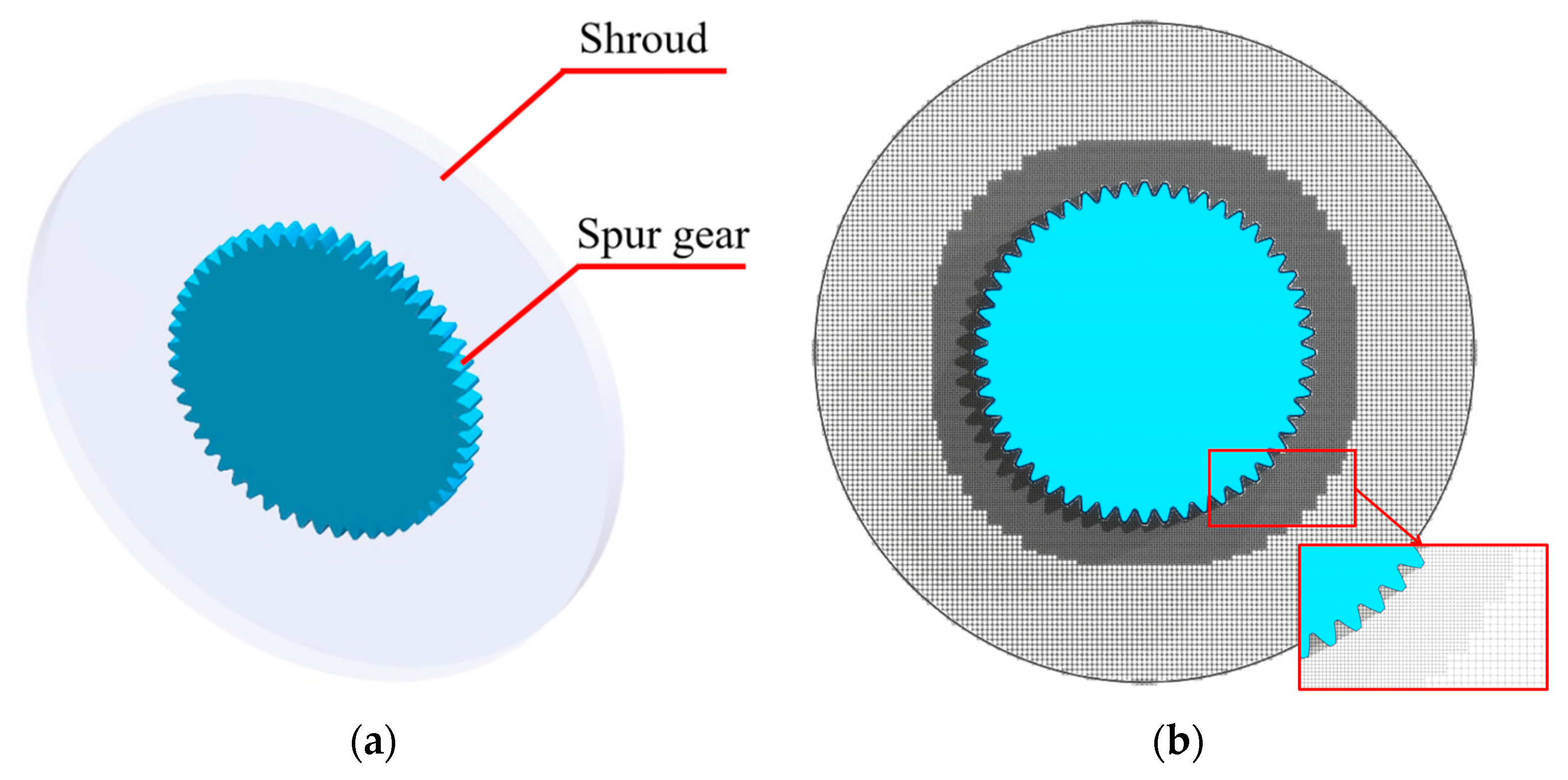
2.2. Geometry and Numerical Setup

A cylindrical spur gear whose main parameters as Handschuh et al. [30] was chosen to produce a direct comparison between the numerical and experimental results. Table 1 enumerates some essential characteristics of the spur gear. To investigate spur gear’s windage losses with various shroud sizes matching Handschuh’s experiments, the air is assumed to be at normal temperatures and pressures, whose density is 1.225 kg/m3 and viscosity is 1.7894 × 10⁻⁵ Pa·s. The rotating speed of the gear is changed from around 2500 rpm to about 15,000 rpm (the tangential velocity value of the gear is about 259.34 m/s), reflecting the typical working conditions of high-speed aeronautic gears. This speed value is varied later in this study. The air is incompressible when the Mach number (the proportion of linear velocity to sound speed) is less than 0.3 at the rotational speed of approximately 6300 rpm. On the other hand, at speeds greater than 6300 rpm, the air becomes compressible. To capture the flow characteristics near the gear wall and limit the number of lattice points influencing the computational efficiency, the near static wall refinement algorithm is adopted to highly refine the small regions near the spur gear, as shown in Figure 2.

3. Results and Discussion

Based on the above real geometrical parameters of the spur gear, four groups of simulations with different lattice sizes are carried out to investigate the dependence analysis of the LBM model. The spur gear is rotating with a shroud whose radial clearance Cr is 16.66 mm and axial clearance Ca is 30.23 mm (i.e., ζr = Cr/Rp = 0.1009, ζa = Ca/bg = 1.0644). When the rotational speed is about 5100 rpm, the measured experimental windage power losses are about 500 W, as presented by Handschuh et al. [30]. The detailed lattice sizes and numerical results of these three groups are listed in Table 2. Simulations were conducted on an AMD EPYC 7302 16-core Processor at 3.00 GHz. As shown in Table 2, all numerical windage power losses of the following models compare well with the experimental measurements. Considering the precision and accuracy of the calculation and flow field information, the finest resolution (Group 1) of these LBM models was recommended.

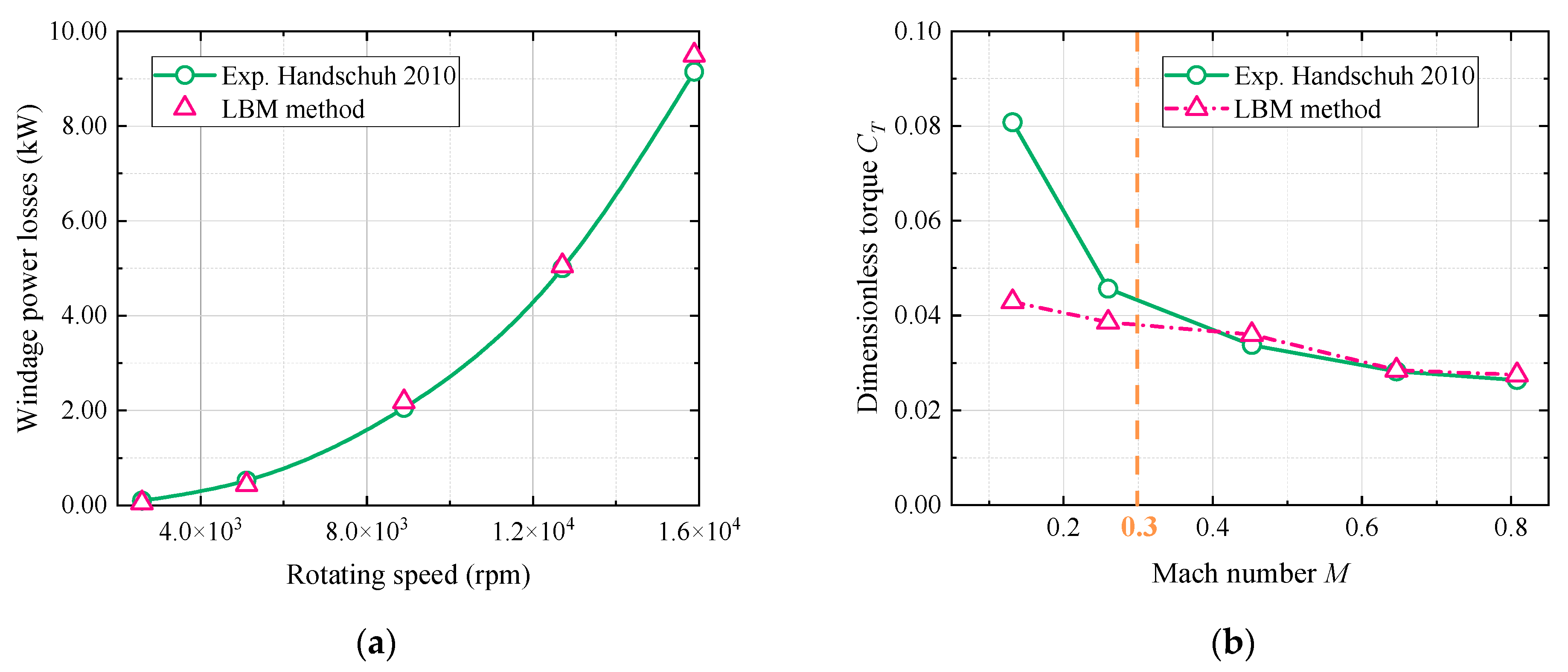
3.1. Verification of CFD Model

To further verify the effectiveness of the above CFD model exploiting the LBM method to estimate the windage losses, the numerical windage losses of the shrouded spur gear (ζr = 0.1009, ζa = 1.0644) are compared with experiments of Handschuh et al. [30] at a rotating speed ranging from 2500 rpm to 15,000 rpm, as shown in Figure 3. As shown in Figure 3a, the changing trends of the numerical and experimental windage losses are the same; they are proportional to the cube of the rotating speed. Simulation results are equivalent to real experimental measurements with an average difference of less than 6.7% (ignoring the measured data for about 2600 rpm, whose uncertainties are greatest), which validates the validity of the CFD method. More than that, the dimensionless windage torque of the gear (CT) is also presented in Figure 3b. When the rotating speed is low (ng < 5900 rpm, Ma < 0.3), the dimensionless value of the resisting torque can be regarded as a constant. The torque value evidently begins to fall, especially when the rotating speed exceeds 5900 rpm. At this point, the air becomes compressible instead of incompressible, as the Mach number is over 0.3. Additionally, it is noticeable that the windage power losses can reach about 10 kW for a single gear, even with a shroud inhibiting the flow motion and power loss generation. In a word, the numerical findings correlate qualitatively quite well with experiments, which confirms the precision and suitability of the CFD model based on the LBM method developed for shrouded spur gear.

3.2. Influence of the Shroud

A spur gear’s windage losses can be calculated by multiplying the dimensionless torque CT by the air density ρair, the angular speed ω to the power of three, and the pitch radius Rp to the power of five, namely, Pwi = 0.5CTρairω3Rp5. When the gear is in free configuration, the formulas of the dimensionless torque CT-free have been theoretically developed and verified by experiments and CFD simulation by Diab et al. [6]. Considering the laminar or turbulent flows, the dimensionless torque coefficient CT-free for the unrestricted scenario is given as follows:
C T - f r e e = 2 n L π 5 2 m L 1 Re * m L R * R p 5 Laminar   zone + 2 n T π 5 2 m T 1 Re m T 1 Re * m T R * R p 5 Turbulent   zone   + z ε a 4 b g R p 1 + 2 1 + x a z 4 1 cos ϕ 1 + cos ϕ 3
As is known to all, the static pressure and windage losses would be rapidly reduced when the gear is in a shrouded configuration. A torque containment factor Cζ is introduced to represent the torque-reducing degree with regard to the free case for the shrouded gear. The dimensionless torque coefficient CT-shroud for the enclosed scenario is given as follows:
C T - s h r o u d = C ζ C T - f r e e
In addition, the compressibility of air cannot be ignored once the Mach number exceeds 0.3. Then, the fluid density will be reduced, which can be calculated as follows:
ρ a i r = 1 + γ 1 2 π n g R P 30 V S 2 1 / γ 1 ρ a i r
where γ represents the gas constant, γ = 1.4. VS represents the sound speed, VS equals 340 m/s at 15 °C and 1 atm.
Put Equation (4) into Equation (3), and then the torque coefficient CT-shroud for the enclosed case can be expressed as follows:
C T - s h r o u d = C ζ C T - f r e e 1 + γ 1 2 π n g R P 30 V S 2 1 / γ 1
Namely,
C T - s h r o u d = C ζ C T - f r e e
With
C T - f r e e = C T - f r e e 1 + γ 1 2 π n g R P 30 V S 2 1 / γ 1
This paper covers only the cylindrical shroud used for spur gears, and the axial and radial dimensions (or the ratio of radial clearance ζr = Cr/Rp and axial clearance ζa = Ca/bg) are the major concern in examining how it affects windage losses.
Depending on the LBM method’s numerical configuration, the windage losses of the gear in different shrouded configurations are further explored. The numerical dimensional windage torque CT-shroud is plotted in Figure 4, Figure 5 and Figure 6 for different configurations, and the spur gear’s theoretical windage losses in its unconstrained configuration calculated based on Diab’s formulas [6] are also superimposed. Some findings obtained from the numerical investigations in Figure 4, Figure 5 and Figure 6 are concluded as follows:
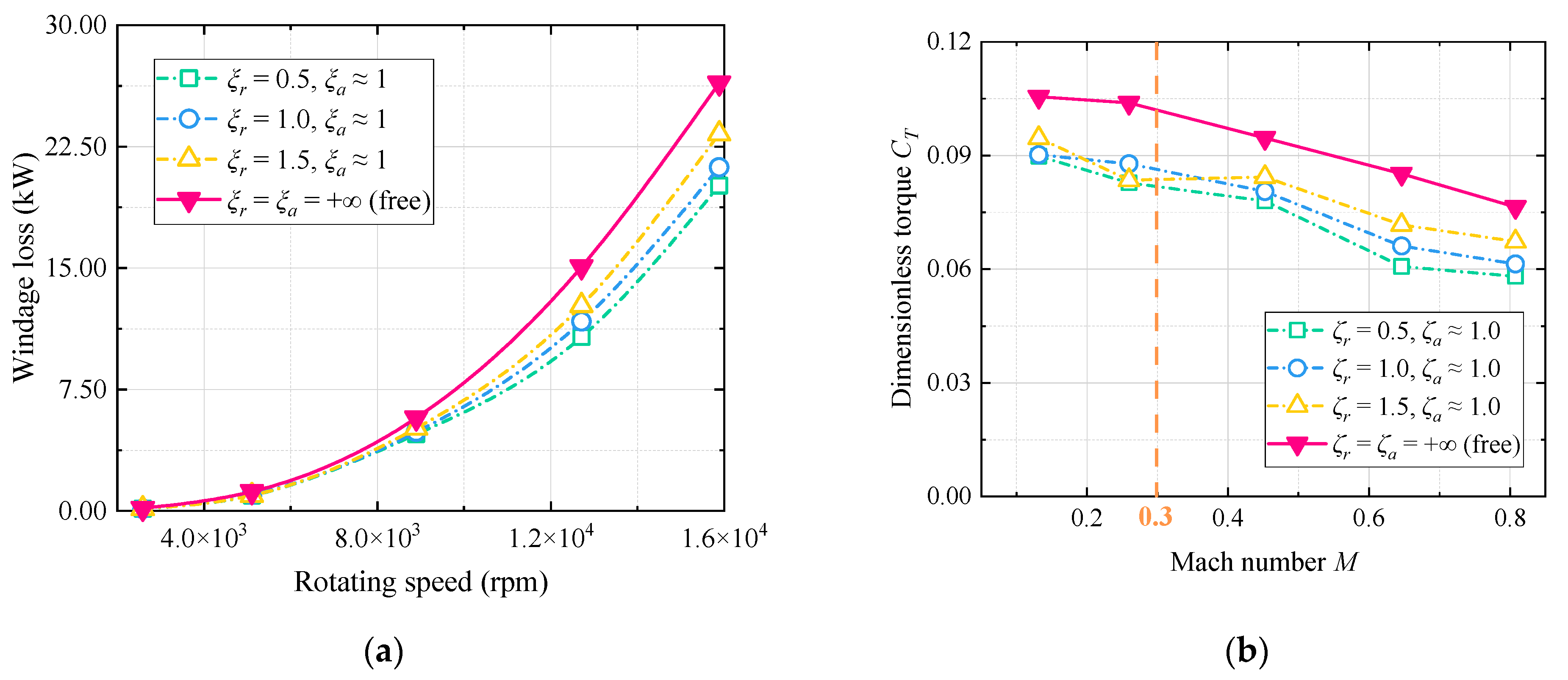
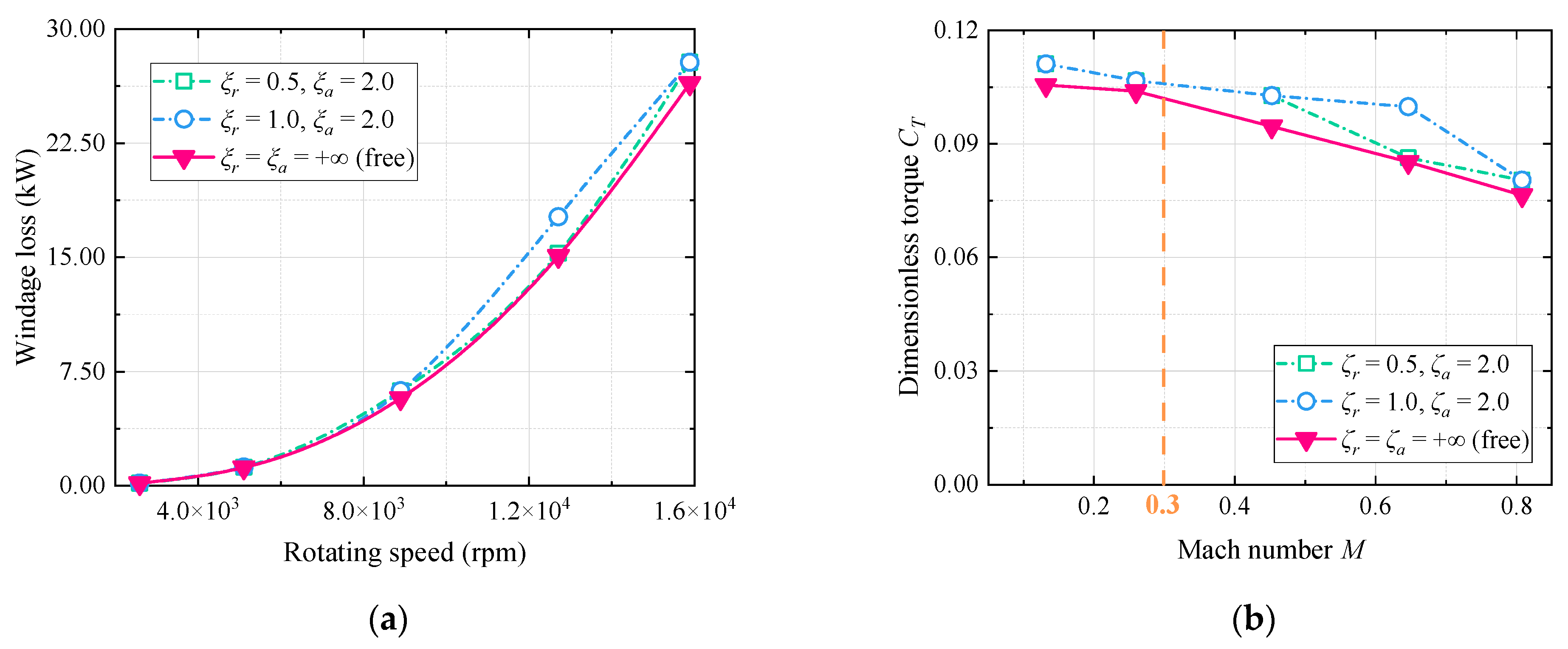
  • The numerical gear power losses with a large clearance (ζr ≥ 0.5 and ζa ≥ 1.0) are close to the maximum theoretical power losses of an unshrouded gear. In other words, a loose shroud has no obvious containment effect on the gear power losses. Compared to Figure 3, a tight shroud would significantly reduce the gear power losses. It has been reduced by at least 50% of windage losses for ζr = 0.1009 and ζa = 1.0644 with respect to the case of ζr = 0.5 and ζa = 1.0.
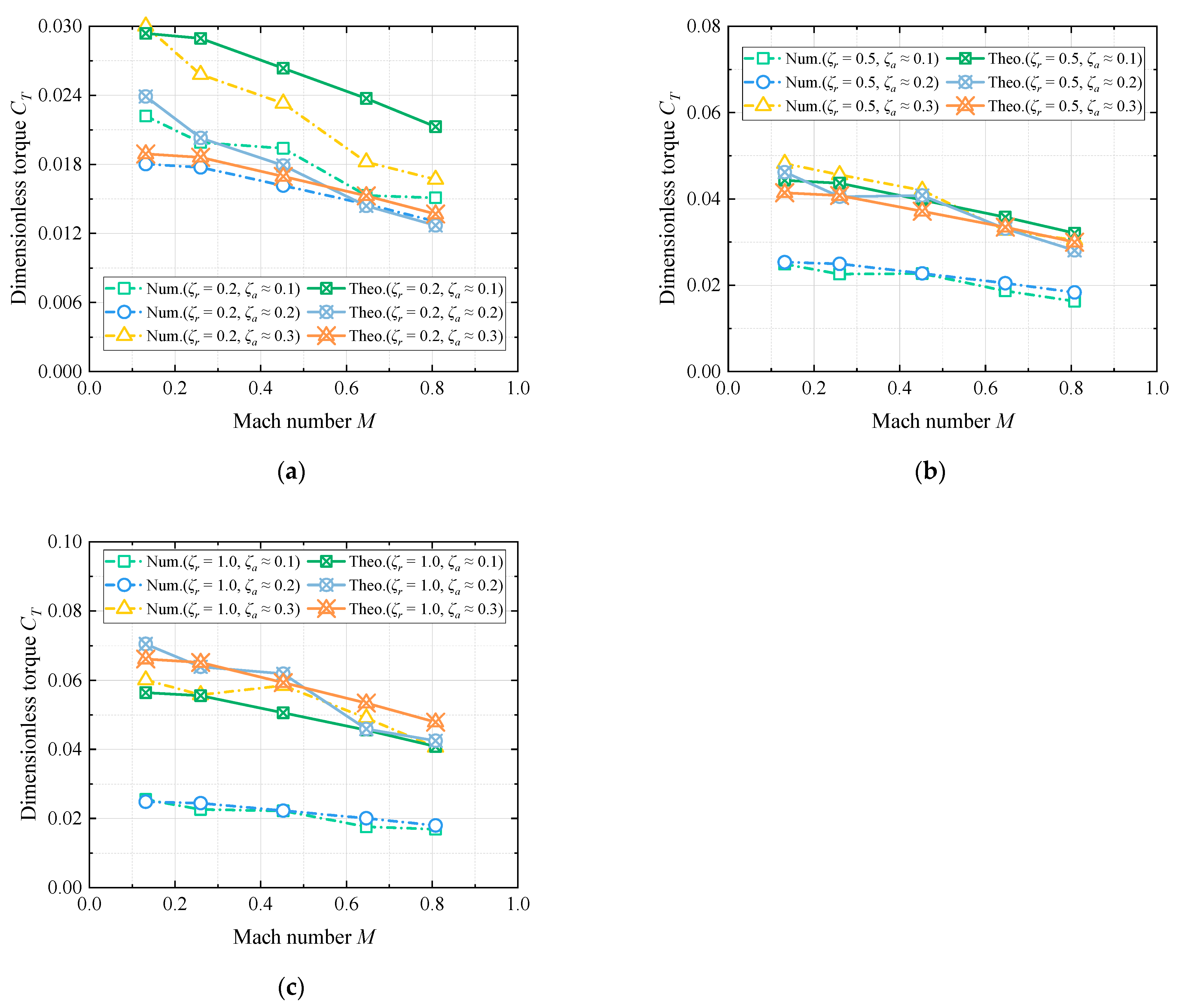
  • Even with a shroud, the windage losses are proportional to the cube of the rotating speed. The dimensionless torque CT has little change when the rotating speed falls below about 5900 rpm and the Mach number is 0.3. Once the Mach number increases, the dimensionless value will decrease obviously. The most important cause of this is the increasingly apparent compressible flow phenomenon of the air.
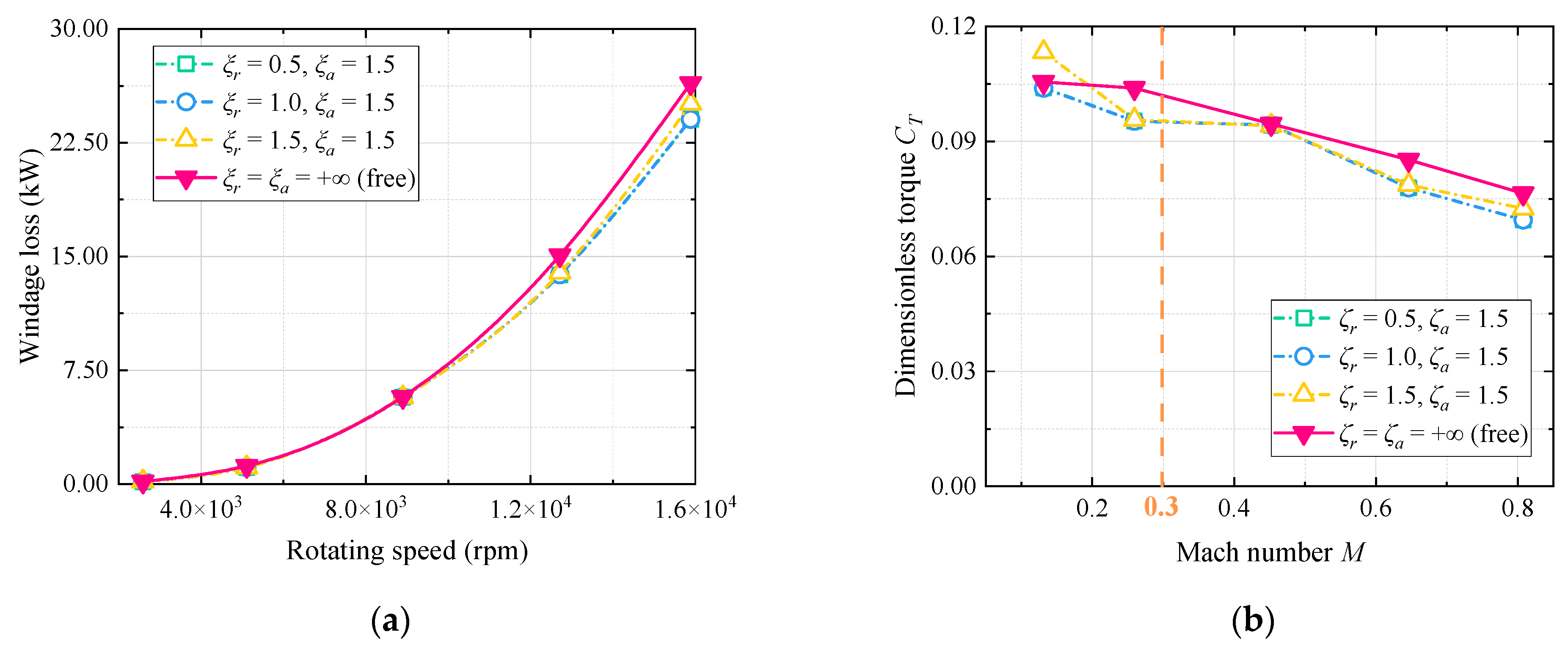
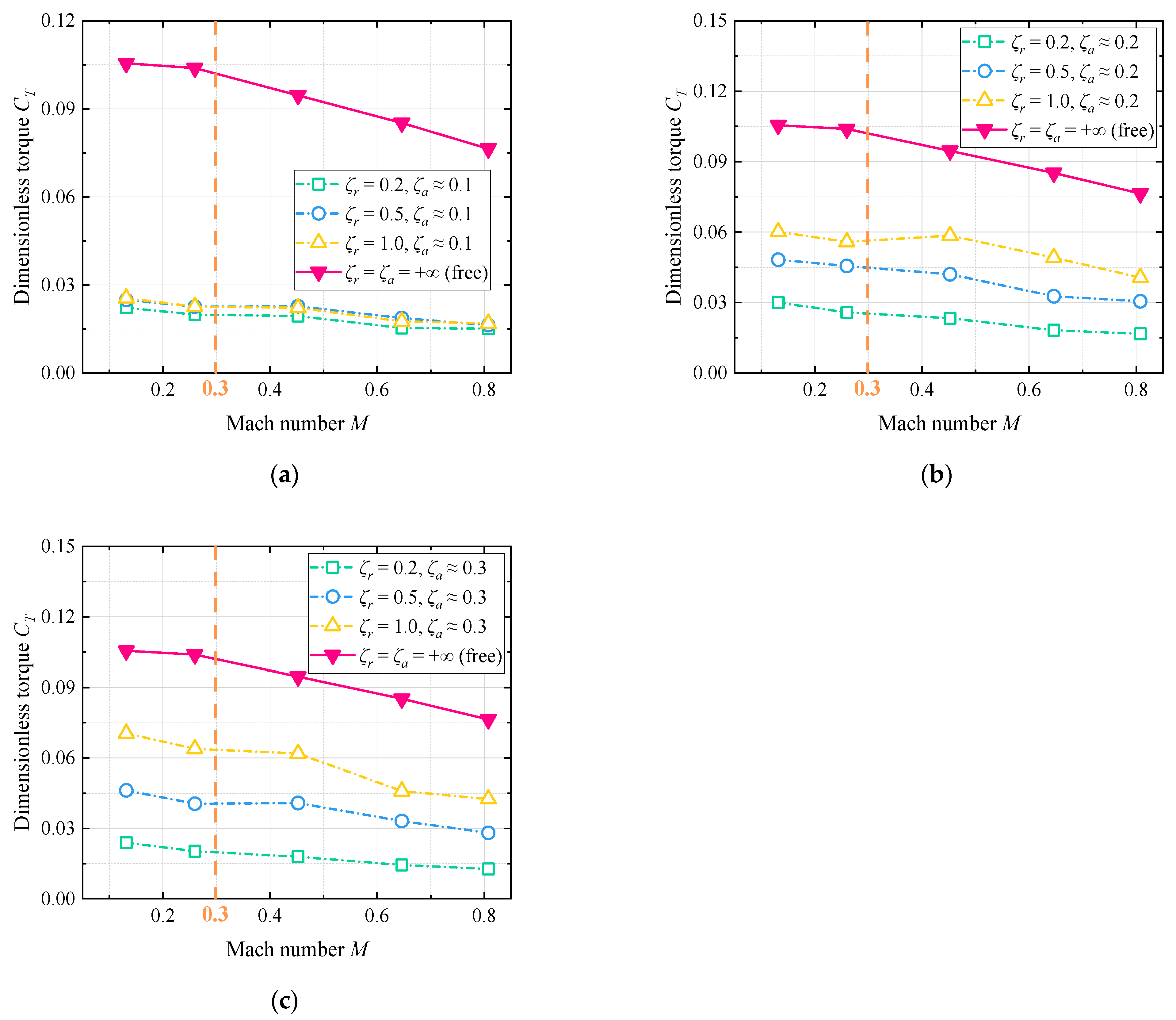
  • Windage losses or dimensionless torques are increasing with the increases of the axial clearance of the shroud compared to Figure 4 to Figure 5. The losses are approaching the theoretical maximum values, even exceeding them. This changing trend is reasonable and acceptable considering the deficiencies in both numerical and theoretical methods.
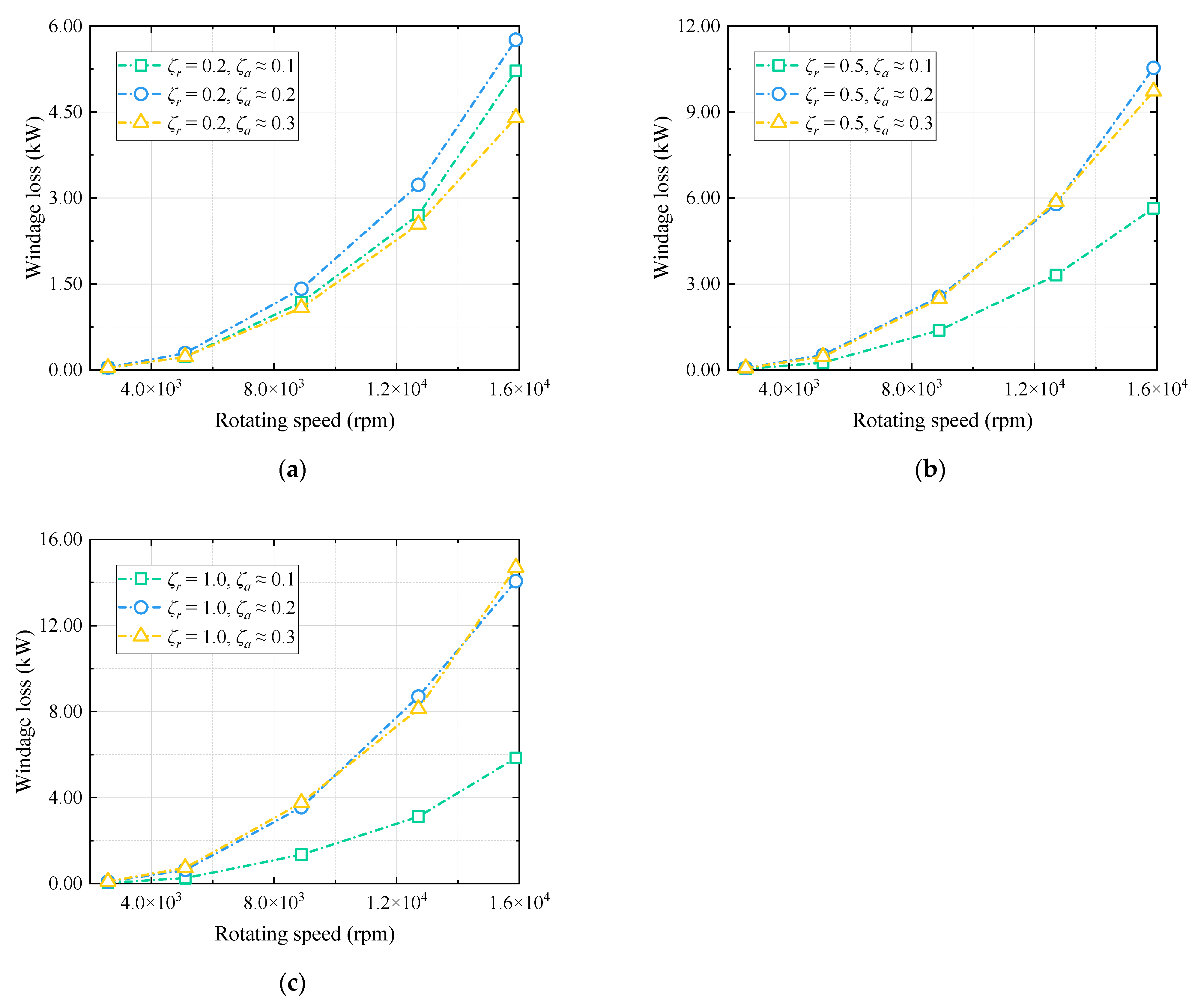
  • As for the same axial clearance ζa of the shroud, the radial clearance changed ζr from 0.5 to 1.5, and the windage losses had no significant changes. It is a similar finding to a 2021 study that claimed that the high-speed gear mostly generates airflow that is between 1.0 and 1.5 times the gear’s radius in a radial direction [14]. This scope is governed by the gear teeth. As for the same radius clearance ζr, the radial clearance changed ζr from 1.0 to 2.0, and the variation in windage losses is obvious.
Given that these observations are obtained mainly from the cases with larger clearances, smaller clearances are further investigated to discuss the shroud’s containment impact. The axial clearance between the spur gear and the tight shroud is set to 3 mm, 6 mm, and 9 mm, namely, ζa is about 0.1, 0.2, and 0.3. Meanwhile, the ratio of radial clearance is set to 0.2, 0.5, and 1.0, respectively. The numerical results including windage power losses and dimensionless torque values are presented in Figure 7, Figure 8, Figure 9 and Figure 10 for different configurations, and the theoretical dimensionless torque of a spur gear in free configuration is also superimposed. Some findings from the numerical analysis are also concluded, as follows:
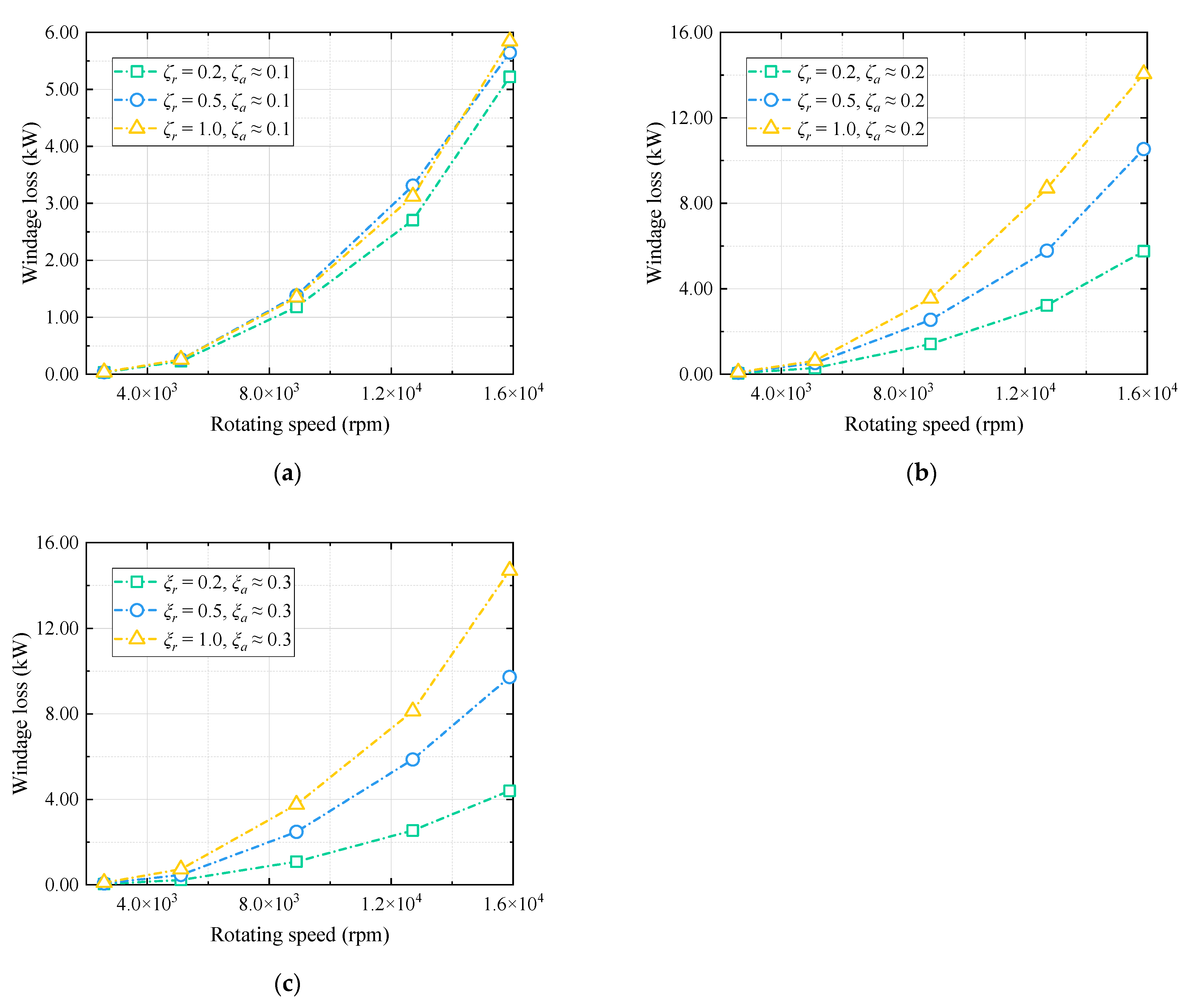
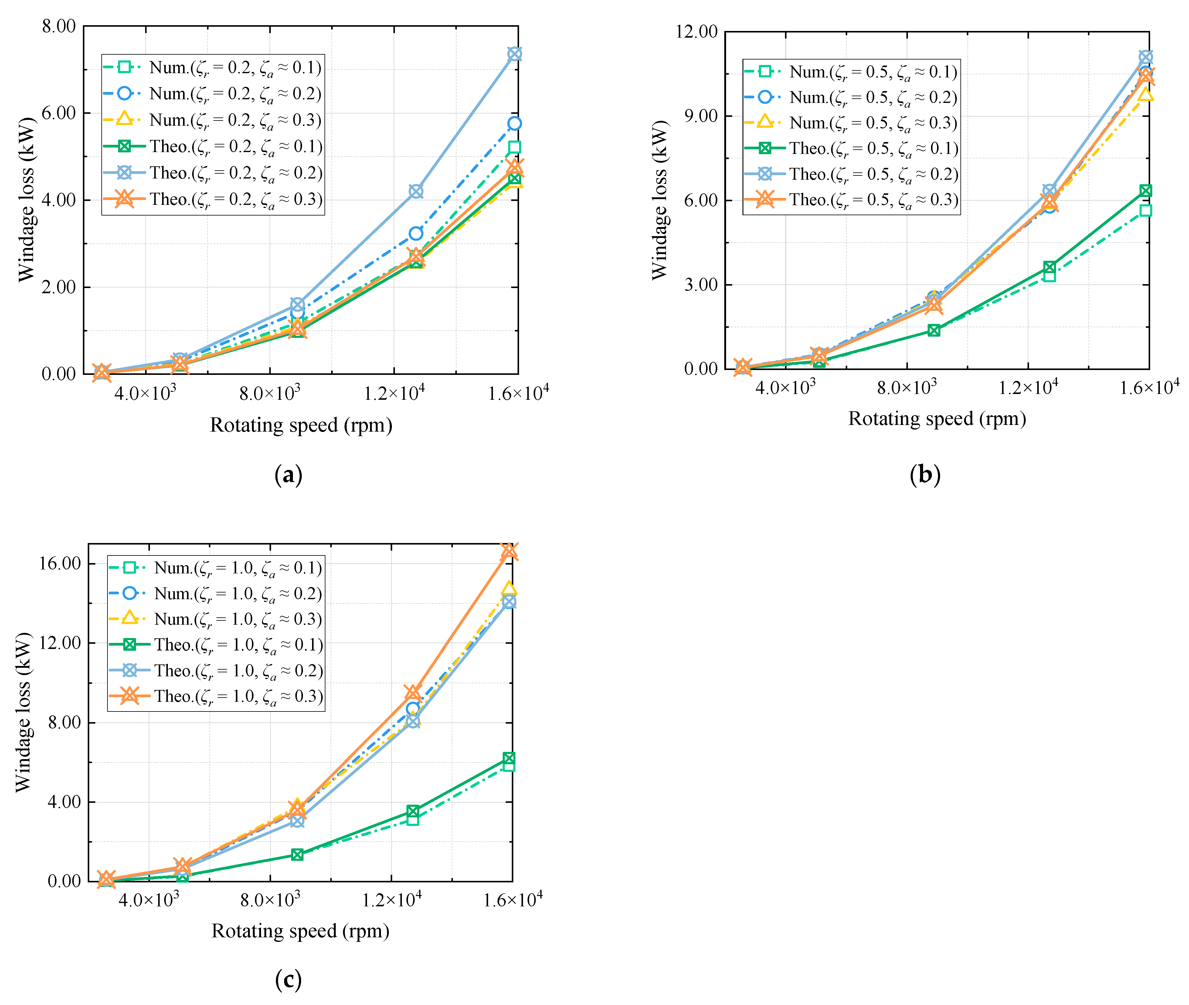
  • It is apparent that the gear’s windage losses with a tight shroud (ζr ≤ 1.0 and ζa ≤ 0.3) still rapidly increase with the rotating speed, as shown in Figure 7 and Figure 9. As in the incompressible flow (M ≤ 0.3), the dimensionless torque CT changes little with the increase in the Mach number. As the Mach number continues to grow (M ≥ 0.3), the torque coefficient CT declines (see Figure 8 and Figure 10).
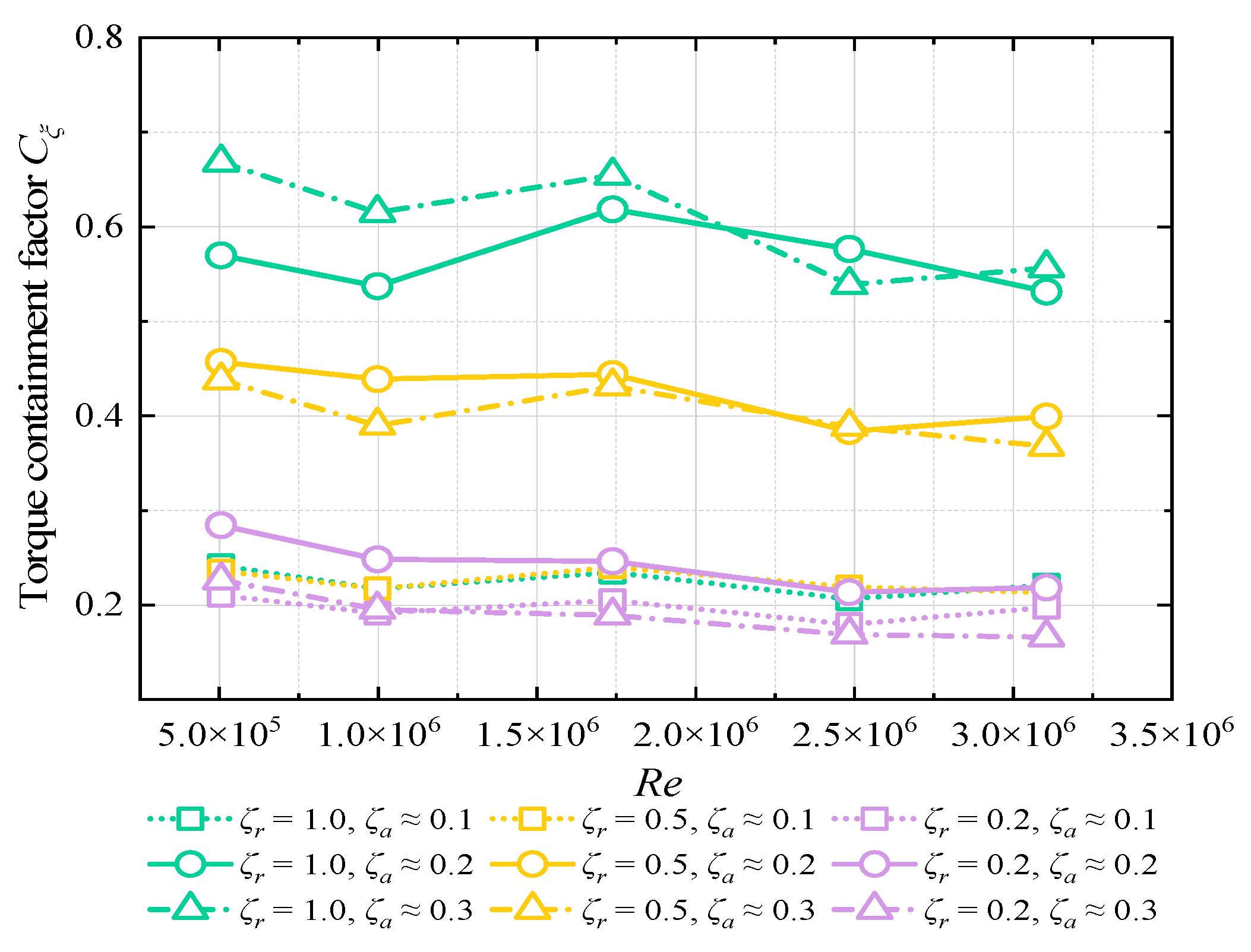
  • In contrast to a loose shroud (ζr ≥ 0.5 and ζa ≥ 1), a tight shroud (ζr ≤ 1.0 and ζa ≤ 0.3) obviously restrains the generation of gear windage power losses. Especially for ζr = 0.2, ζa ≈ 0.3, the windage losses decrease more than 83.3%. It is the same as the previous conclusion by Winfree [38]. In general, the windage losses decrease as the radial or axial clearances reduce. However, in the case of small radial clearance (ζr = 0.2), continuous reduction of axial clearance may become counterproductive. That is going to be particularly important when ζr = 0.2, ζa ≈ 0.3, as the corresponding power losses are much smaller than those of ζr = 0.2, ζa ≈ 0.1 and ζr = 0.2, ζa ≈ 0.2, and about an equal number of the tight shroud configuration of ζr ≈ 0.005, ζa ≈ 0.045, according to Handschuh et al. [30]. This could be due to the strengthening of the axial pump effect when the radial and axial clearances are so narrow that the assembly of the spur gear and tight shroud is analogous to a part of a gear pump, as stated by Zhu et al. [21]. Therefore, from the perspective of the containment of the windage losses, the axial clearance cannot be too small.

3.3. Torque Containment Factor

Based on the above analysis, the windage power losses brought on by a loose shroud on a high-speed spur gear (e.g., ζr ≥ 0.5 and ζa ≥ 1) are close to the gear power losses in free configurations. When a tight shroud (e.g., ζr ≤ 1.0 and ζa ≤ 0.3) approaches the spur gear, the generated windage losses are significantly suppressed. Even though the windage losses are greatly reduced to 15% of the power losses of the gear in free air, as a tight shroud is fairly close to the gear (e.g., ζr ≈ 0.005, ζa ≈ 0.045; ζr ≈ 0.1, ζa ≈ 0.045), the narrow gap between the shroud and the gear is not suitable from the point of gear cooling performance. Therefore, a tighter shroud configuration (e.g., ζr ≤ 1.0 and ζa ≤ 0.3) needs to be further analyzed for the gearbox body design, especially for the prediction of the torque containment factor Cζ.
According to Fondelli et al. [24], the torque containment factor Cζ is determined by the ratio Vr of the fluids enclosed in the gear in the shroud and the gear, as well as the Reynolds number Re. The torque containment factor Cζ is expressed through a fitting process, as follows:
C ζ = 1 1 + k R e n 1 V r n 2
With
R e = ρ a i r ω R p 2 μ
And
V r = V F l u i d V G e a r
The decreased degree of a shrouded gear’s windage losses in comparison to a free gear is represented by Equations (8)–(10). Considering the analysis above, the torque containment factor Cζ should be related to the Reynolds number Re, the axial clearance ratio ζa, and the radial clearance ratio ζr. We extracted the torque containment factor Cζ from the results according to Equations (6) and (7), and the change rules of the torque containment factor against rotating speed with different configurations are presented in Figure 11. It is indicated that the curves of the containment factor are nearly straight when the distance between the gear and tight shroud is very small. As is described in Fondelli et al. [24], the torque containment factor Cv, as the ratio of the windage power losses of a shrouded gear to the losses of a gear in free air, has taken into account the special impact of the air compressibility at high speed. However, air compressibility has been solely considered as in Equations (6) and (7), so this decay factor of torque Cζ has little to do with the rotating speed.
Furthermore, an empirical equation is obtained through a fitting process to explain the relationship between the clearance ratios ζa, ζr, and the containment factor Cζ and described by Equations (11) and (12). The positive correlation between CFD data and empirical equations is highlighted by the coefficient of determination (R2) of 0.9812 and the sum of squared residuals (SSE) of 0.004008.
C ζ = p 0 + p 1 ζ r + p 2 ζ a + p 3 ζ r 2 + p 4 ζ r ζ a + p 5 ζ a ζ a 2
With
p 0 = 0.1726 p 1 = 0.2043 p 2 = 3.505 p 3 = 0.3025 p 4 = 2.268 p 5 = 9.275
Considering the above-developed model of the torque containment factor integrating the free torque coefficient, the theoretical windage power losses can be determined compared with numerical ones, as shown in Figure 12 and Figure 13. The theoretical calculations agree well with the numerical findings, with the relative difference of the windage power losses of no more than 8.76%. It is suggested that the estimation precision and accuracy of the theoretical method for the windage power losses in a relatively tight shrouded spur gear are significantly improved by leveraging the torque containment factor and air compressibility effect at high speed.

4. Conclusions

The Lattice Boltzmann method (LBM) was utilized to forecast the windage phenomenon of a spinning gear in order to examine the windage power losses of a shrouded spur gear. The primary goal of this research was to empirically demonstrate a relationship between the dimensionless torque (windage power losses) and the radial and axial clearances from a cylindrical shroud to a spur gear.
First of all, the CFD model modeling by the Lattice Boltzmann Method was verified by reproducing experiments in the scientific literature, where the windage losses from a rotating spur gear with a tight cylindrical shroud surrounding it were measured. Numerical predictions achieve very good agreement with experimental findings with a relative error not exceeding 6.7%.
In order to evaluate the containment effect of the shroud on windage losses, the CFD approach was subsequently expanded to simulate the gear inside various cylindrical shrouds. It is well known that the windage effects would be reduced when the gear is enclosed by suppressing the air angular momentum driven by the rotating speed. Additionally, the results indicated that the decrease in windage losses is related to the shroud dimensions, including the radial and axial clearances. The impact of a somewhat loose shroud on windage losses is minimal. In the case of small radial clearance, the continuous reduction of axial clearance may increase windage losses.
A torque containment factor integrating the air compressibility at high Mach numbers is introduced to represent the reduction in torque (windage power losses) for the shrouded gear compared to the free case. The demonstration of a direct relationship between the shroud clearances and the torque containment factor is studied. Based on the above findings, the theoretical method to predict the windage power losses of a gear in free air has been improved according to this connection relationship that integrates the air compressibility effect. This improved method can now estimate a gear’s windage losses in an enclosed cylindrical arrangement, obtain high goodness of fit and satisfactory effect with the numerical results, and be applied to the preliminary design stage.

Author Contributions

Conceptualization, Y.D. and C.Y.; methodology, X.Z.; software, C.Y.; validation, Y.D. and X.Z.; formal analysis, X.Z.; investigation, C.Y.; resources, Y.D.; data curation, C.Y.; writing—original draft preparation, X.Z.; writing—review and editing, C.Y.; visualization, X.Z.; supervision, X.Z. and Y.D.; project administration, Y.D.; funding acquisition, Y.D. All authors have read and agreed to the published version of the manuscript.

Funding

This research was funded by the National Natural Science Foundation of China (Grant No. 52305081 and 52475078), the Natural Science Foundation of Changsha City of China (Grant No. kq2208275), and the National Defense Pre-Research Foundation of China (Grant No. KY-1044-2023-0451).

Institutional Review Board Statement

Not applicable.

Informed Consent Statement

Not applicable.

Data Availability Statement

The original contributions presented in this study are included in the article, and further inquiries can be directed to the corresponding author.

Conflicts of Interest

The authors declare no conflicts of interest.

Nomenclature

bgteeth width, mm
Caaxial clearance, mm
Crradial clearance, mm
CTdimensionless torque factor
CT-freedimensionless torque factor in pure air
CT-freedimensionless torque factor in pure air when Mach number exceeds 0.3
CT-shrouddimensionless torque factor in an enclosed case
Cζtorque containment factor
MaMach number
ngrotating speed, rpm
Pwiwindage losses, W
Re *critical Reynolds number = 3 × 10⁵
Rppitch radius, mm
VFluidfluid volume, mm3
VGeargear volume, mm3
Vrvolume ratio
VSsound speed, m/s
xatooth form coefficient
Zteeth number
γgas constant
ωangular velocity, rad/s
ρairair density, kg/m3
ρairair density when Mach number exceeds 0.3, kg/m3
ζaaxial clearance factor
ζrradial clearance factor

References

  1. Handschuh, R.F.; Kilmain, C.J. Operational Influence on Thermal Behavior of High-Speed Helical Gear Trains; American Helicopter Society: Phoenix, AZ, USA, 9–11 May 2006. [Google Scholar]
  2. Winfree, D.D. Reducing gear windage losses from high speed gears. In Proceedings of the International Design Engineering Technical Conferences and Computers and Information in Engineering Conference, Baltimore, MD, USA, 10–13 September 2000. [Google Scholar]
  3. Anderson, N.E.; Loewenthal, S.H. Effect of geometry and operating conditions on spur gear system power loss. J. Mech. Des. 1981, 103, 151–159. [Google Scholar] [CrossRef]
  4. Townsend, D. Gear Handbook, the Design, Manufacture and Application of Gears; McGraww-Hill: New York, HY, USA, 1992. [Google Scholar]
  5. Hill, M.J.; Kunz, R.F.; Medvitz, R.B.; Handschuh, R.F.; Long, L.N.; Noack, R.W.; Morris, P.J. CFD Analysis of Gear Windage Losses: Validation and Parametric Aerodynamic Studies. J. Fluids Eng. Trans. ASME 2011, 133, 031103. [Google Scholar] [CrossRef]
  6. Diab, Y.; Ville, F.; Velex, P.; Changenet, C. Windage losses in high speed gears—Preliminary experimental and theoretical results. J. Mech. Des. 2004, 126, 903–908. [Google Scholar] [CrossRef]
  7. Zhu, X.; Dai, Y.; Ma, F.Y. Development of a quasi-analytical model to predict the windage power losses of a spiral bevel gear. Tribol. Int. 2020, 146, 106258. [Google Scholar] [CrossRef]
  8. Seetharaman, S.; Kahraman, A.; Moorhead, M.D.; Petry-Johnson, T.T. Oil Churning Power Losses of a Gear Pair: Experiments and Model Validation. J. Tribol. Trans. ASME 2009, 131, 022202. [Google Scholar] [CrossRef]
  9. Seetharaman, S.; Kahraman, A. Load-Independent Spin Power Losses of a Spur Gear Pair: Model Formulation. J. Tribol. Trans. ASME 2009, 131, 022201. [Google Scholar] [CrossRef]
  10. Seetharaman, S.; Kahraman, A. A Windage Power Loss Model for Spur Gear Pairs. Tribol. Trans. 2010, 53, 473–484. [Google Scholar] [CrossRef]
  11. Massini, D.; Fondelli, T.; Andreini, A.; Facchini, B.; Tarchi, L.; Leonardi, F. Experimental and Numerical Investigation on Windage Power Losses in High Speed Gears. J. Eng. Gas Turbines Power 2018, 140, 082508. [Google Scholar] [CrossRef]
  12. Ruzek, M.; Ville, F.; Velex, P.; Boni, J.B.; Marchesse, Y. On windage losses in high-speed pinion-gear pairs. Mech. Mach. Theory 2019, 132, 123–132. [Google Scholar] [CrossRef]
  13. Ruzek, M.; Marchesse, Y.; Ville, F.; Velex, P. Windage power loss reductions in high-speed gear pairs. Forsch. Ingenieurwesen 2019, 83, 387–392. [Google Scholar] [CrossRef]
  14. Dai, Y.; Xu, L.J.; Zhu, X.; Ouyang, B. Application of an unstructured overset method for predicting the gear windage power losses. Eng. Appl. Comput. Fluid 2021, 15, 130–141. [Google Scholar] [CrossRef]
  15. Pallas, S.; Marchesse, Y.; Changenet, C.; Ville, F.; Velex, P. A windage power loss model based on CFD study about the volumetric flow rate expelled by spur gears. Mech. Ind. 2012, 13, 317–323. [Google Scholar] [CrossRef]
  16. Pallas, S.; Marchesse, Y.; Changenet, C.; Ville, F.; Velex, P. Application and validation of a simplified numerical approach for the estimation of windage power losses in spur gears. Comput. Fluids 2013, 84, 39–45. [Google Scholar] [CrossRef]
  17. Marchesse, Y.; Changenet, C.; Ville, F.; Velex, P. Investigations on CFD Simulations for Predicting Windage Power Losses in Spur Gears. J. Mech. Des. 2011, 133, 024501. [Google Scholar] [CrossRef]
  18. Voeltzel, N.; Marchesse, Y.; Changenet, C.; Ville, F.; Velex, P. On the influence of helix angle and face width on gear windage losses. Proc. Inst. Mech. Eng. Part C J. Mech. Eng. Sci. 2016, 230, 1101–1112. [Google Scholar] [CrossRef]
  19. Al-Shibl, K.; Simmons, K.; Eastwick, C.N. Modelling windage power loss from an enclosed spur gear. Proc. Inst. Mech. Eng. Part A J. Power Energy 2007, 221, 331–341. [Google Scholar] [CrossRef]
  20. Ruzek, M.; Brun, R.; Marchesse, Y.; Ville, F.; Velex, P. On the reduction of windage power losses in gears by the modification of tooth geometry. Forsch. Ingenieurwesen 2023, 87, 1029–1036. [Google Scholar] [CrossRef]
  21. Zhu, X.; Bian, J.N.; Dai, Y. A quasi-analytical prediction method for gear load-independent power losses for shroud approaching. Eng. Sci. Technol. 2023, 48, 101562. [Google Scholar] [CrossRef]
  22. Li, L.L.; Wang, S.M. Research on the calculation method of windage power loss of aviation spiral bevel gear and experiment verification. Proc. Inst. Mech. Eng. Part E J. Process Mech. Eng. 2023. [Google Scholar] [CrossRef]
  23. Li, L.L.; Wang, S.M.; Liu, L.L. An Analysis Model for Predicting Windage Power Loss of Aviation Spiral Bevel Gears Under Optimal Injection Jet Layout. Tribol. Trans. 2023, 66, 1057–1077. [Google Scholar] [CrossRef]
  24. Fondelli, T.; Andreini, A.; Facchini, B. Numerical Investigation on Windage Losses of High-Speed Gears in Enclosed Configuration. AIAA J. 2018, 56, 1910–1921. [Google Scholar] [CrossRef]
  25. Zhang, Y.Z.; Hou, X.Y.; Zhang, H.; Zhao, J. Numerical Simulation on Windage Power Loss of High-Speed Spur Gear with Baffles. Machines 2022, 10, 416. [Google Scholar] [CrossRef]
  26. Li, L.L.; Wang, S.M.; Zou, H.R.; Cao, P.T. Windage Loss Characteristics of Aviation Spiral Bevel Gear and Windage Reduction Mechanism of Shroud. Machines 2022, 10, 390. [Google Scholar] [CrossRef]
  27. Zhang, Y.Z.; Li, L.L.; Zhao, Z.Q. Optimal Design of Computational Fluid Dynamics: Numerical Calculation and Simulation Analysis of Windage Power Losses in the Aviation. Processes 2021, 9, 1999. [Google Scholar] [CrossRef]
  28. Li, L.L.; Wang, S.M.; Zhang, X.Y.; Li, Z.B.; Li, F.; Zou, H.R. Numerical Calculation Analysis and Characteristic Research on Windage Loss of Oil-Jet Lubricated Aviation Gear Pair. Int. J. Aerosp. Eng. 2022, 2022, 7499587. [Google Scholar] [CrossRef]
  29. Li, L.L.; Wang, S.M. Experimental Study and Numerical Analysis on Windage Power Loss Characteristics of Aviation Spiral Bevel Gear with Oil Injection Lubrication. Stroj. Vestn. J. Mech. Eng. 2023, 69, 235–247. [Google Scholar] [CrossRef]
  30. Handschuh, R.F.; Hurrell, M.J. Initial experiments of high-speed drive system windage losses. In Proceedings of the International Conference on Gears, Garching, Germany, 4–6 October 2010. [Google Scholar]
  31. Marchesse, Y.; Ruzek, M.; Ville, F.; Velex, P. On windage power loss reduction achieved by flanges. Forsch. Ingenieurwesen 2022, 86, 389–394. [Google Scholar] [CrossRef]
  32. Wei, K.; Lu, F.X.; Bao, H.Y.; Zhu, R.P. Mechanism and reduction of windage power losses for high speed herringbone gear. Proc. Inst. Mech. Eng. Part C J. Mech. Eng. Sci. 2023, 237, 2014–2029. [Google Scholar] [CrossRef]
  33. Atencio, B.N.; Yao, H.D.; Chernoray, V. Experiments and Lattice-Boltzmann Simulation of Flow in a Vertically Aligned Gearbox. J. Tribol. 2023, 145, 114103. [Google Scholar] [CrossRef]
  34. Gong, R.; Gong, Q.; Che, H.J.; Zhang, Z.G. Numerical Investigation on Churning Loss Torque and Oil Distribution of Reducer Based on Lattice Boltzmann Method. Tribol. Trans. 2021, 64, 968–979. [Google Scholar] [CrossRef]
  35. Li, Q.H.; Xu, P.; Li, L.; Xu, W.X.; Tan, D.P. Investigation on the Lubrication Heat Transfer Mechanism of the Multilevel Gearbox by the Lattice Boltzmann Method. Processes 2024, 12, 381. [Google Scholar] [CrossRef]
  36. Ambrose, S.; Morvan, H.; Simmons, K. Investigation of oil jet impingement on a rotating gear using lattice boltzman method (LBM). In Proceedings of the ASME Turbo Expo 2018: Turbomachinery Technical Conference and Exposition, Oslo, Norway, 11–15 June 2018. [Google Scholar]
  37. Hu, X.Z.; Li, P.F.; Quan, C.; Wang, J.N. CFD investigation on oil injection lubrication of meshing spur gears via lattice Boltzmann method. Lubricants 2022, 10, 184. [Google Scholar] [CrossRef]
  38. Winfree, D.D. Reducing gear windage losses from high speed gears and applying these principles to actual running hardware. In Proceedings of the ASME 2013 International Design Engineering Technical Conferences and Computers and Information in Engineering Conference, Portland, OR, USA, 4–7 August 2013. [Google Scholar]
Figure 1. Velocity directions available from a lattice node in a D3Q27 model. The numbers 0–26 represent different velocity directions.
Applsci 14 09174 g001
Figure 2. Figures of the numerical: (a) three-dimensional model; (b) lattice refinement.
Applsci 14 09174 g002
Figure 3. Comparison of numerical and experimental results for ζr ≈ 0.1009 and ζa ≈ 1.0644: (a) windage losses Pwi [30]; (b) dimensionless torque CT [30].
Applsci 14 09174 g003
Figure 4. Numerical findings against the rotating speed or Mach number for ζa ≈ 1.0: (a) windage losses Pwi; (b) dimensionless torque CT.
Applsci 14 09174 g004
Figure 5. Numerical findings against the rotating speed or Mach number for ζa ≈ 1.5: (a) windage losses Pwi; (b) dimensionless torque CT.
Applsci 14 09174 g005
Figure 6. Numerical findings against the rotating speed or Mach number for ζa ≈ 2.0: (a) windage losses Pwi; (b) dimensionless torque CT.
Applsci 14 09174 g006
Figure 7. Numerical windage losses against the rotating speed with different clearances: (a) ζa = 0.1; (b) ζa = 0.2; (c) ζa = 0.3.
Applsci 14 09174 g007
Figure 8. Dimensionless torque CT against Mach number M with different clearances: (a) ζa = 0.1; (b) ζa = 0.2; (c) ζa = 0.3.
Applsci 14 09174 g008
Figure 9. Numerical windage losses against the rotating speed with different clearances: (a) ζr = 0.2; (b) ζr = 0.5; (c) ζr = 1.0.
Applsci 14 09174 g009
Figure 10. Dimensionless torque CT against Mach number M with different clearances: (a) ζr = 0.2; (b) ζr = 0.5; (c) ζr = 1.0.
Applsci 14 09174 g010
Figure 11. Change rules of torque containment factor with different configurations.
Applsci 14 09174 g011
Figure 12. Comparisons of numerical and theoretical windage losses: (a) ζr = 0.2; (b) ζr = 0.5; (c) ζr = 1.0.
Applsci 14 09174 g012
Figure 13. Comparisons of numerical and theoretical dimensionless torque: (a) ζr = 0.2; (b) ζr = 0.5; (c) ζr = 1.0.
Applsci 14 09174 g013
Table 1. Gear geometrical parameters.
ParameterValue
Number of teeth52 (-)
Module6.35 (mm)
Gear width28.4 (mm)
Pitch radius165.1 (mm)
Pressure angle25 (°)
Tooth profileStandard
Table 2. Numerical results against different lattice sizes.
GroupGlobal
Resolution (mm)
Local Refined Resolution (mm)Total Number of Lattice Nodes (-)Wall Clock Time (min)Numerical Windage Losses (W)
152.5639,504310443
263370,080196475
373.5235,456154425
Disclaimer/Publisher’s Note: The statements, opinions and data contained in all publications are solely those of the individual author(s) and contributor(s) and not of MDPI and/or the editor(s). MDPI and/or the editor(s) disclaim responsibility for any injury to people or property resulting from any ideas, methods, instructions or products referred to in the content.

