Article

Automated Evaluation of C-ITS Message Content for Enhanced Compliance and Reliability

1
Faculty of Transportation Sciences, Czech Technical University in Prague, 110 00 Prague, Czech Republic
2
Department of Electronic Engineering, National Taipei University of Technology, Taipei 10608, Taiwan
*
Authors to whom correspondence should be addressed.
Appl. Sci. 2024, 14(20), 9526; https://doi.org/10.3390/app14209526
Submission received: 11 September 2024 / Revised: 13 October 2024 / Accepted: 16 October 2024 / Published: 18 October 2024

Abstract

:
In the field of Cooperative Intelligent Transport Systems (C-ITSs), the traditional approach to testing often emphasizes technological parameters, leaving the validation of message content insufficiently addressed. Since the content of these messages is crucial for the correct functioning of C-ITS, this article demonstrates the potential for automated evaluation of C-ITS message content against relevant standards. It leverages our novel tools, Karlos and C-ITS SIM, to facilitate this process. Through detailed laboratory testing and data analysis, the study showcases the effectiveness of these automated solutions in enhancing the accuracy and reliability of message content validation.

1. Introduction

C-ITSs represent one of the rapidly expanding technologies in the field of intelligent transport infrastructure and are set to play a crucial role in the future of mobility, including autonomous driving. These systems enable communication between vehicles (OBUs—On-Board Units), roadside infrastructure (RSUs—Roadside Units), and central systems (BO—Back Office). While C-ITSs are designed to improve safety, efficiency, and sustainability in transportation, the realization of these benefits is highly dependent on the accurate and seamless interaction between various subsystems and the ability of these systems to function across national borders. The international C-Roads project emphasizes this, focusing on the harmonization and standardization of C-ITS across Europe, but challenges remain in achieving true interoperability and ensuring compliance with evolving standards.
Implementing C-ITSs on a large scale presents numerous technical challenges. These include ensuring consistent communication quality, addressing security vulnerabilities in open networks, and managing the complexity of multi-vendor environments where equipment from different manufacturers must interact seamlessly. Moreover, accurately measuring the safety and efficiency gains from these systems remains an open question, as the effectiveness of C-ITSs heavily depends on the specific use cases and environments in which they are deployed.
For instance, while studies [1,2,3] have outlined potential benefits, there remains a gap in the literature when it comes to systematic evaluations of how C-ITS messages align with standards and regulations. Furthermore, as more car manufacturers develop their own C-ITS units, ensuring compliance with these standards is crucial to avoid fragmentation and loss of interoperability. These challenges underline the need for robust testing and validation methods.
Within C-ITSs, there are various types of messages that are essential for communication between different entities in the system. These messages address different aspects, such as safety, information exchange, or traffic optimization, and their correct functioning is critical for ensuring the overall interoperability of the system [4,5].
The primary goal of this paper is to address one of these key challenges: the automated evaluation of C-ITS message content. By using tools such as Karlos and C-ITS SIM, this work aims to enhance the reliability of the message validation processes, providing detailed laboratory testing and rigorous data analysis. This approach will not only ensure that the messages comply with standards but also help identify gaps and potential improvements in message content structure, thereby contributing to the overall effectiveness of C-ITSs.
This state-of-the-art review examines various studies related to V2X communication and C-ITS systems, emphasizing their contributions to the field and identifying gaps in the current literature.
Several studies have extensively explored the technical metrics associated with V2X communication. For instance, Hofer et al. [6] conducted a comparative analysis between field measurements and vehicle-in-the-loop testing, focusing on critical parameters such as received signal strength and packet error rates. Similarly, Nilsson [7] investigated the effects of multipath propagation on vehicle-to-infrastructure (V2I) and vehicle-to-vehicle (V2V) communications, proposing various test scenarios that could influence signal strength. Liu et al. [8] contributed to this field by testing LTE and DSRC communication, examining parameters like delay and packet loss while adopting a pedestrian perspective. Experimental scenarios were conducted in diverse environments, including a campus, an urban street, and a suburban neighborhood, highlighting the applicability of cooperative systems in varied contexts. Additionally, Soua et al. [9] focused on the adjacent channel interference effect, which can pose challenges for ensuring successful communication, particularly when multiple services are utilized simultaneously. Sassi et al. [10] also explored the impact of transmission range in V2X communication, utilizing their custom-developed Arrada LocoMate OBU transmission system to evaluate the packet loss ratio parameter concerning modulation and traffic density. Bae et al. [11] presented the results of field tests of a DSRC-based V2X communication system, analyzing key performance indicators such as packet error and reception rate, received channel power indicator, and inter-packet gap across three different signal strength modes: 5, 11, and 20 dBm. In addition, Ge et al. [12] conducted further tests on communication within cooperative systems, proposing a testing procedure that includes field tests with a focus on the packet delivery time parameter and its dependency on the number of vehicles. Finally, Duan et al. [13] presented a classic procedure for evaluating the maximum distance between transmitter and receiver and packet delay in V2V and V2I communication systems.
The implementation of Cooperative Intelligent Transport Systems (C-ITSs) has been scrutinized in studies examining its effects on traffic efficiency and safety. Agriesti et al. [4] evaluated the impacts of C-ITSs during lane closures on highways, finding that C-ITS messages can significantly improve traffic flow and reduce delays. In a similar vein, Ekedebe et al. [14] reported measurable benefits in vehicle travel time and reduced gas emissions from V2I communications. Furthermore, Studer et al. [3] explored the deployment of C-ITSs and automated vehicles within the C-Roads platform, assessing their impacts on transportation infrastructure and defining future directions for their development and implementation. Their study emphasizes the effectiveness of these systems in enhancing cooperative and automated mobility, which could be evaluated through automatic analysis methodologies. Additionally, Chen et al. [15] tested the adaptability of connected vehicles in platoon driving mode, defining criteria such as traffic efficiency, safety, and driver comfort. Their findings indicate that platooning can contribute positively to all these criteria, further supporting the potential of C-ITS in improving overall transportation systems.
The challenges posed by implementing cooperative systems have also been addressed in the literature. For example, Weiss [16] outlined the benefits of cooperative systems while describing testing methodologies using the sim TD tool. Chen et al. [17] explore the obstacles faced in China, providing valuable insights into the parameters required for V2X communication and detailing the technological comparisons essential for addressing these challenges. Maglogiannis et al. [18] contribute to this discussion by investigating key parameters such as the packet error rate, signal-to-noise ratio, range, and latency, along with a proposed testing methodology that includes communication logging during vehicle-to-infrastructure interactions. Broz et al. [19] focused on maintaining reliable V2X communication within tunnels, highlighting the limitations of Global Navigation Satellite System (GNSS) signals and proposing alternative approaches for enhancing traffic safety.
Studies comparing different communication technologies, such as Bey et al. [20] and Mavromatis et al. [21], provide insights into the performance metrics of DSRC and LTE technologies. These comparisons highlight the variations in packet delivery success rates depending on environmental factors and the number of vehicles. Additionally, Shi et al. [22] examine the testing of LTE-V and 802.11p communication technologies specifically in intersection areas. Their study contributes to understanding how these technologies perform under conditions relevant to real-world traffic scenarios, further enhancing the comparative analysis of V2X communication systems.
From the conducted research, it can be seen that most of the articles focus on the actual technical design of cooperative systems and their parameters such as speed, number of packets, delay, etc. Some articles focus at least partially on cooperative messages, but not in detail, only at a general level (number of received, discarded messages). Thus, the authors are not aware of any studies that have addressed content validation of cooperative messages, both in terms of conformance to standards and in terms of testing the content of messages in the field.

2. Materials and Methods

To evaluate the effectiveness and compliance of C-ITSs, a series of controlled laboratory tests were conducted. This section outlines the specific types of C-ITS messages that were the focus of the testing, the relevant standards that guided the evaluation process, the tools developed and employed for testing, and the methodology used to ensure rigorous and reliable results. By following this structured approach, the study aims to provide a clear and replicable framework for assessing the accuracy and compliance of C-ITS message content.

2.1. Types of C-ITS Messages

C-ITS messages are critical components of the communication between vehicles, roadside infrastructure, and central systems. These messages serve various purposes, from enhancing safety to optimizing traffic flow and providing real-time information to road users. The types of messages used in C-ITS vary depending on their specific function within the system. Some of the key message types include:
  • Cooperative Awareness Messages (CAMs): provide real-time data about the position, speed, and status of vehicles.
  • Decentralized Environmental Notification Messages (DENMs): alert vehicles and infrastructure about hazardous conditions or events.
  • In-Vehicle Information Messages (IVIs): convey road sign information and other relevant data directly to drivers.
  • Signal Phase and Timing Messages (SPaTs): communicate traffic signal status and timing to vehicles.
  • MAP Messages: provide detailed descriptions of intersections, including lane configurations and connections.
  • Signal Request Messages (SRMs) and signal Status Messages (SSMs): used for communication between vehicles and traffic signal controllers, often for prioritizing emergency vehicles or public transport.
Among these, CAMs and DENMs are the most fundamental, as they enable vehicles and infrastructure to share crucial information that supports safe and efficient transportation. This study focuses specifically on the testing and validation of CAMs and DENMs.

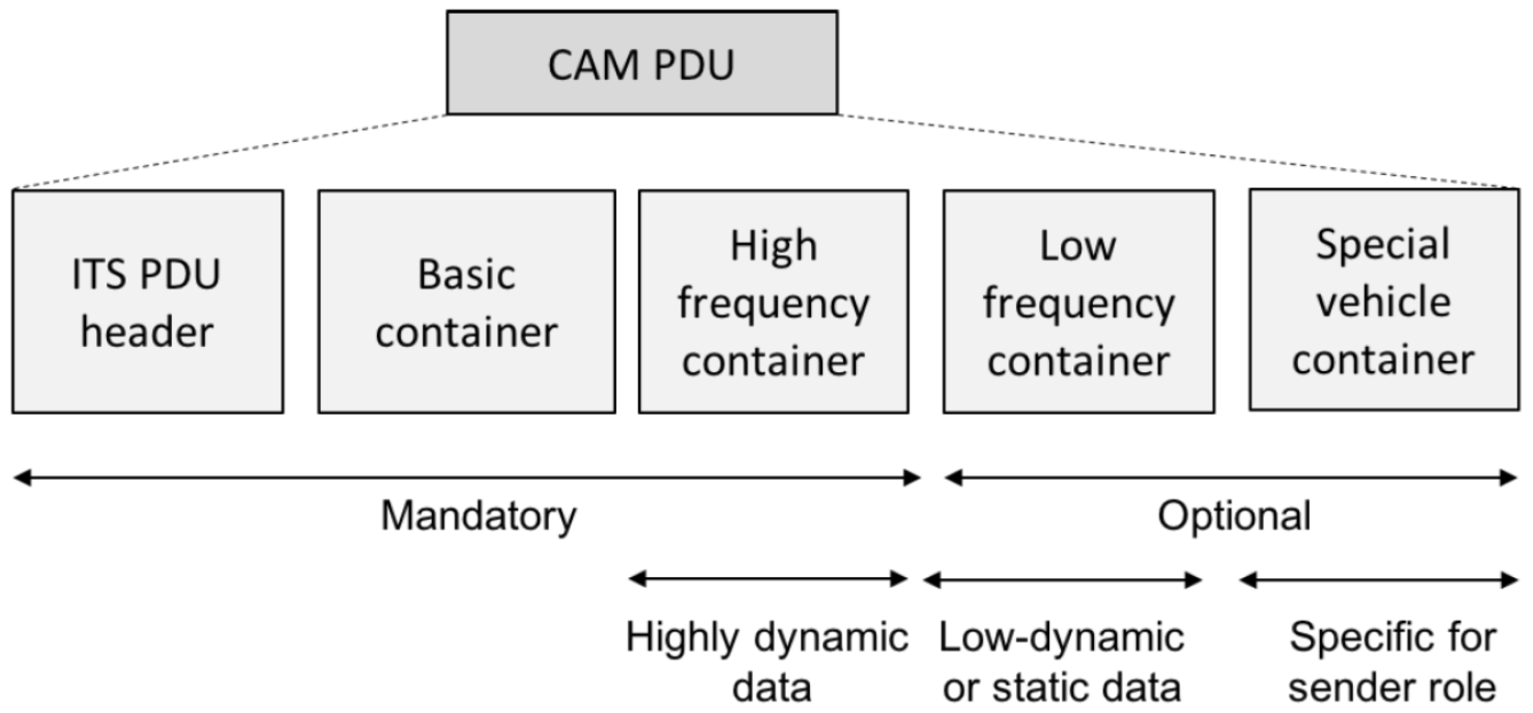
2.1.1. Cooperative Awareness Messages (CAMs)

CAMs are a key element within C-ITSs, facilitating communication between vehicles and infrastructure by providing crucial information about the current state and location of vehicles. CAMs are standardized according to ETSI EN 302 637-2—V1.3.1 [23], which defines the structure and content of these messages.
A CAM is divided into several main containers, as shown in Figure 1, which include specific parameters [24]:
  • Basic Container:
    stationType: This parameter specifies the type of the device sending the message (e.g., passenger car, truck, etc.). It helps recipients of the message understand the context in which the message was sent.
    referencePosition: Contains information about the geographical location of the device at the time the message was sent. This includes latitude, longitude, altitude, and measurement accuracy. This parameter is crucial for determining the vehicle’s position and for applications such as navigation and proximity detection.
  • High-Frequency Container:
    This container includes data that changes frequently and is transmitted at a higher frequency. It typically includes information about speed, direction, and the current state of the vehicle. The high-frequency container is mandatory, and its content is important for applications requiring current and dynamic information about the vehicle.
  • Low-Frequency Container:
    This container contains less frequently changed information, transmitted at a lower frequency. It may include static data such as vehicle properties (type, size). According to the standard, the low-frequency container must be included in all CAMs from the first message generated after the activation of the cooperative awareness basic service. Additionally, it must be included if the time elapsed since the last CAM generation with the low-frequency container is equal to or greater than 500 ms.
  • Special Vehicle Container:
    This container holds specific information about vehicles that may have special requirements or characteristics. Similar to the low-frequency container, the special vehicle container must be included in the first CAM after the activation of the CA basic service. It must also be included if the time elapsed since the last CAM generation with the special vehicle container is equal to or greater than 500 ms.
This text provides a basic overview of CAMs and their container structures. For the purposes of this article, this information is sufficient. The following sections will provide a more detailed examination of specific CAM parameters that were tested and the methods used to verify them.

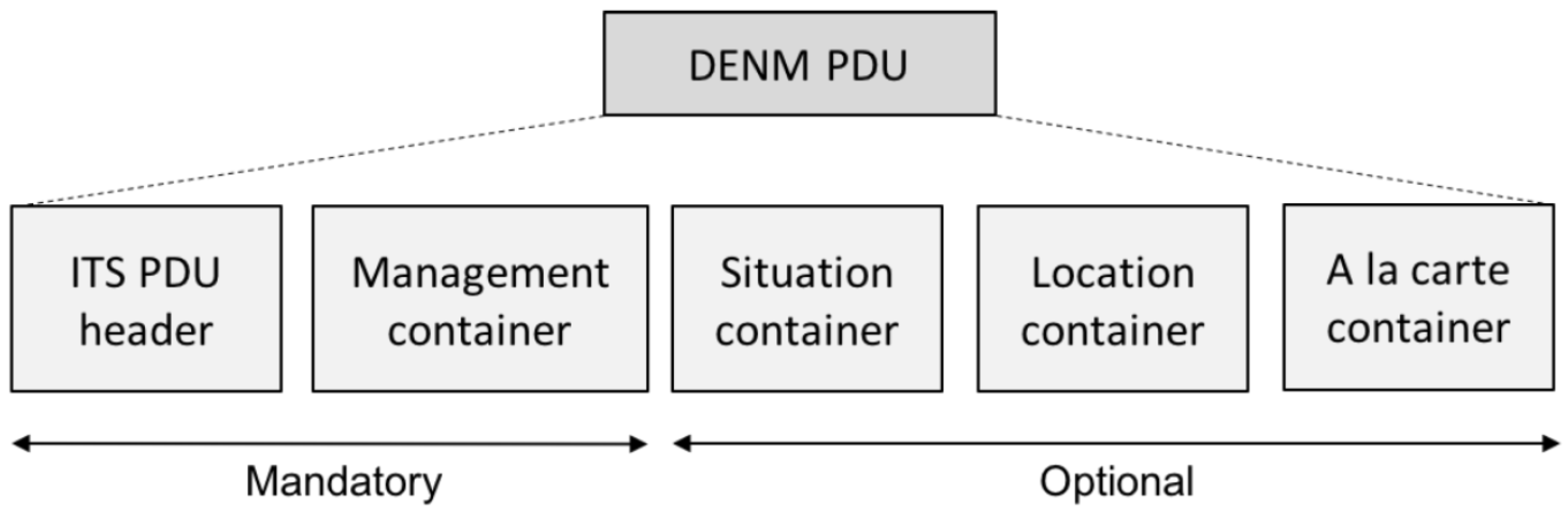
2.1.2. Decentralized Environmental Notification Messages (DENMs)

DENMs are designed to convey environmental information related to traffic events in a decentralized manner. Each DENM consists of a common ITS PDU header followed by several containers that together form the DENM payload. The structure of a DENM, shown in Figure 2, is as follows [24]:
  • ITS PDU Header: This header includes information about the protocol version, message type, and Intelligent Transport System Station (ITS-S) ID of the originating ITS-S.
  • DENM Payload: The payload comprises four primary containers, which are transmitted in a fixed sequence:
    Management Container: Contains information pertinent to the management of the DENM, including action IDs, detection times, reference times, and other elements such as termination, event position, relevance distance, relevance traffic direction, validity duration, and transmission interval.
    Situation Container: Provides details about the event type and its context. It must include the informationQuality and eventType elements and may include linkedCause and eventHistory. The informationQuality value ranges from 1 (lowest) to 7 (highest), while eventType includes causeCode and subCauseCode to describe the specific event.
    Location Container: Describes the event’s location. It must include traces and may also include optional elements such as eventSpeed, eventPositionHeading, and roadType.
    à la Carte Container: This container is used to include additional application-specific data not covered by the other containers. It can include elements such as lanePosition, impactReduction, externalTemperature, roadWorks, positioningSolution, and stationaryVehicle, depending on the use case.
Each container in a DENM has specific requirements regarding its presence and the information it must or may contain. The management container and ITS PDU header are mandatory, while the situation, location, and à la carte containers are optional and included based on the specific needs of the message and the context of the event.
DENMs are used to alert road users of detected events and are processed by ITS applications to provide relevant information and warnings. The detailed specifications for each container and its elements are outlined in ETSI EN 302 637-3 [25], providing comprehensive guidelines for effective communication within C-ITS environments.

2.2. Description of Testing Tools

In the context of C-ITSs, precise validation of message content and adherence to standards are critical for ensuring system interoperability and safety. To address these needs, specialized testing tools have been developed. These tools are primarily designed to verify the compliance of messages with relevant standards, as well as to facilitate the transmission and reception of messages under controlled conditions. In this section, we provide an overview of the key tools used in our testing framework, focusing on their specific applications and functionalities.

2.2.1. Karlos

Karlos is a tool designed for analyzing and verifying C-ITS communication. In this article, we focus on analyzing CAM and DENM. The tool processes input PCAP files that contain these messages and generates three main output files from the analysis:
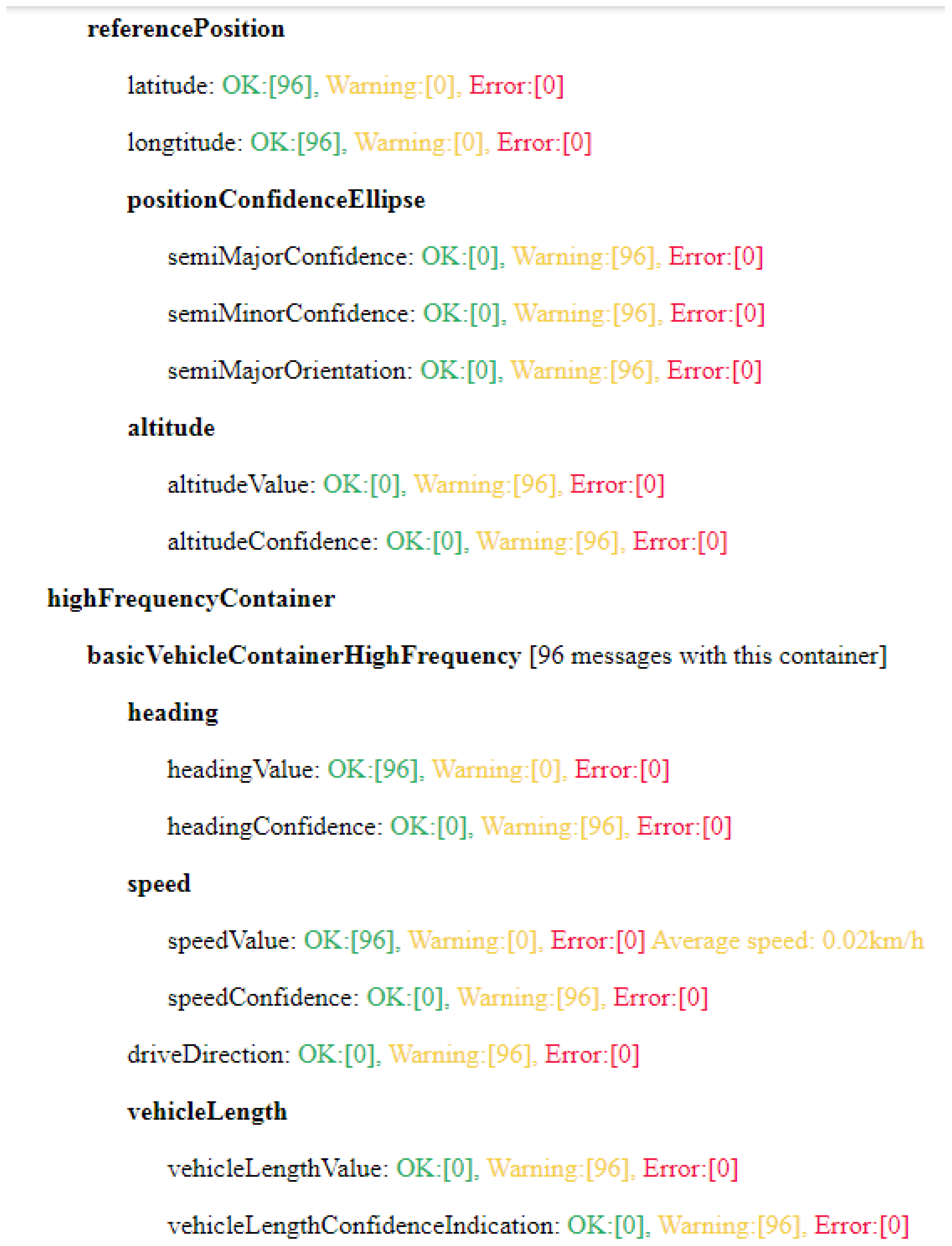
  • Summary—This file contains selected parameters from CAMs/DENMs and compares their values with the relevant ranges defined in the respective standards. Users have the option to specify in advance which parameters will be included in this summary. This approach allows for targeted analysis, such as focusing only on speed values (speedValue) and their deviations from expected values. An example of such a summary is shown in Figure 3. Here, you can see an example of a list of parameters and their evaluation based on the number of messages. The number in brackets indicates the number of messages corresponding to each state (OK, error, warning).
  • Complete List—This file provides detailed information about each individual CAM/ DENM, enabling users to trace specific messages and conduct in-depth analysis. This list is crucial for potential retrospective tracking of anomalies or erroneous messages.
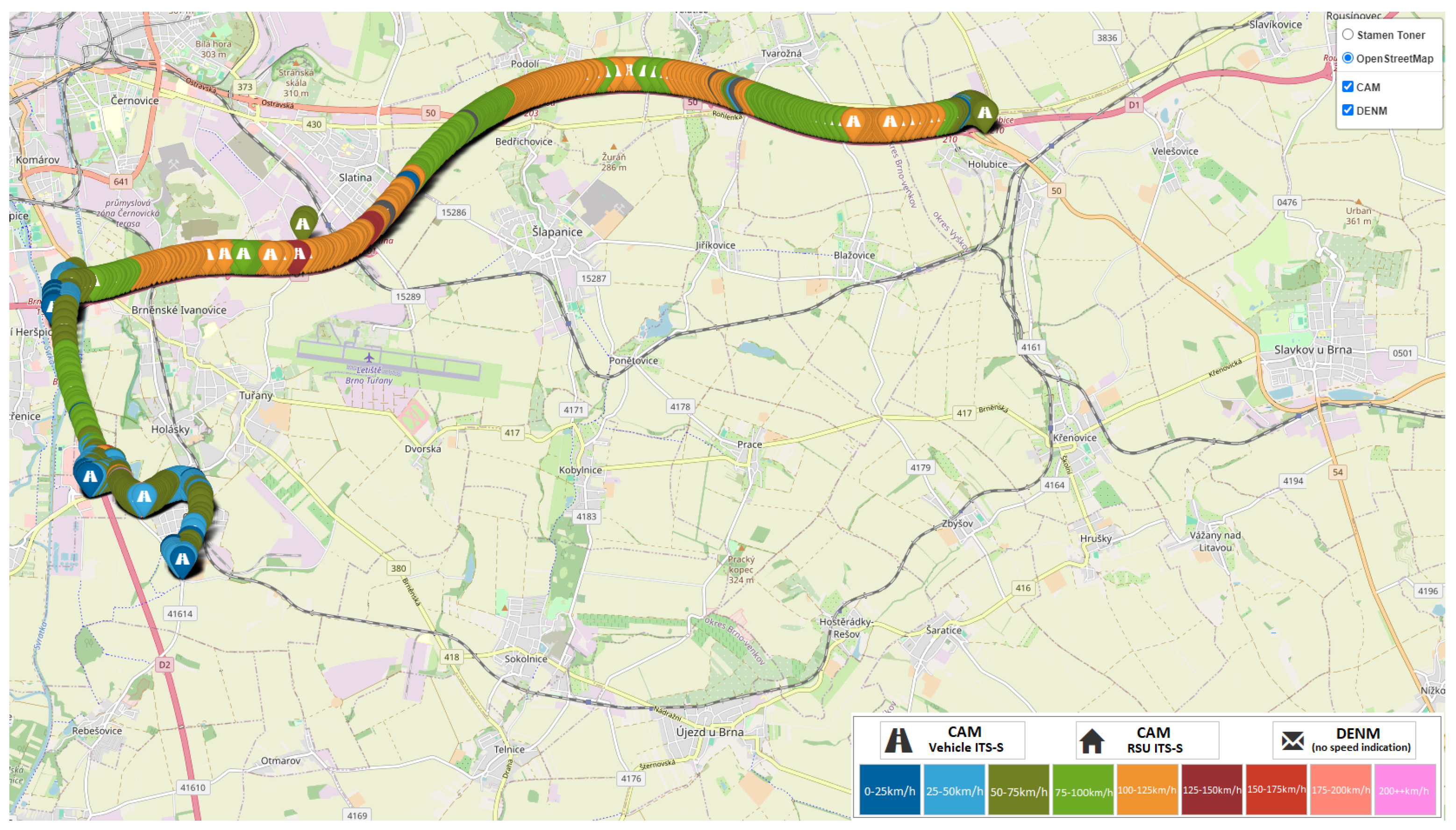
  • Map Visualization—This feature allows CAMs/DENMs to be displayed on a map. Each CAM is shown based on the speed indicated in the message, with different speeds represented by different colors. Each message can be clicked on the map to view detailed information about it. An example of this map visualization is shown in Figure 4.
Karlos also allows users to specify how the analysis should be conducted, enabling filtering of messages based on specific parameters, such as stationID, allowing for a more focused examination of the selected data.
Karlos is developed in Python and utilizes the Wireshark tool, specifically its component tshark, for preprocessing PCAP files.
The output values in the files are categorized into three types:
  • Correct Result—The analyzed parameter value lies within the permissible range according to the specification. If possible, an interpretation of the value is also provided.
  • Result with Warning—This type of result indicates that the parameter value is permissible according to the specification, but its actual significance is limited. This typically occurs in situations where the parameter suggests that the actual value is unavailable or where an optional parameter is missing in the message.
  • Incorrect Result—This result indicates situations where the parameter value lies outside the defined range, or where the parameter indicates too high a measurement uncertainty, rendering the measurement invalid. An incorrect result also occurs when a mandatory parameter is missing in the message.

2.2.2. C-ITS SIM

C-ITS SIM is a specialized tool developed for testing third-party C-ITS units and their practical implementation in C-ITSs. It ensures interoperability and validation by supporting various functionalities, including the broadcasting and reception of CAMs and DENMs, which are crucial for this article.
The tool consists of specific software connected to two On-Board Units (OBUs). This dual-OBU setup is essential for accurate verification of message transmission and reception:
  • Broadcasting Verification: One OBU transmits the messages while the second OBU receives and verifies them. This setup allows for accurate identification of any issues with message transmission, confirming whether the problem lies with the third-party unit or not.
  • Reception Verification: For reception tests, the dual-OBU setup enables double-checking to ensure that any issues with receiving messages are not due to the C-ITS SIM itself. The software allows users to configure expected parameter values for messages and verifies if these parameters are met. An example of receiving messages is shown in Figure 5, which displays the basic interface. On the left side, you can see all the captured C-ITS messages, including those transmitted by the C-ITS SIM. In the center, there is a regularly updated map displaying C-ITS messages according to their geographical location. On the right side, there is a list of OBUs connected to the software, along with the option to connect additional devices.
The tool is designed to handle CAMs and DENMs, among others, but for the purposes of this article, its focus is on how well these messages are transmitted and received. The approach differs from Karlos, as C-ITS SIM involves configuring the desired message parameters in the software and then verifying whether the captured messages meet these parameters. The configuration of these parameters is illustrated in Figure 6.
Users can configure the tool to include specific parameters for CAMs and DENMs. This feature enables targeted testing by allowing users to select which parameters to analyze, such as verifying speed values or other critical data.
The tool automatically logs communication during tests, storing data in PCAP format for easy analysis. It allows users to review and replay test scenarios, providing valuable insights into the performance and accuracy of the C-ITS units.
C-ITS SIM is versatile and can be used for both lab-based and field testing. It has been employed in various testing environments to refine its functionality and address real-world challenges. The tool is designed to be adaptable to new standards and evolving testing needs. It has also been successfully utilized in both national and international testing as part of the C-ROADS project mentioned earlier. Further details about this software, including its additional features, can be found in the article [26].

2.3. Testing Environment

For our testing, two distinct setups were employed for evaluating CAM and DENM handling. The testing was conducted using C-ITS SIM connected to two OBUs, which were responsible for transmitting and receiving messages during different phases of the test. Third-party units were involved both in logging the messages sent by the C-ITS SIM setup and in broadcasting their own messages, which were then captured and analyzed by the C-ITS SIM system.
All communication between the units was captured in PCAP format, which was subsequently analyzed using the tool Karlos (see Section 2.2.1). The entire testing environment was designed for controlled laboratory conditions, focusing on validating the content of the messages.

2.4. Testing Methodology

The testing methodology was designed to assess how various configurations of CAM and DENM were received and broadcast by third-party units.

2.4.1. CAM Scenarios

  • Scenario 1: Third-party OBU as a receiver
Configuration: C-ITS SIM is configured to transmit CAMs with this setup:
  • stationType set to “trailer”, vehicleRole set to “dangerousGoods”
The messages were broadcast by C-ITS SIM, and the third-party unit logged them in order to further analyze whether the received messages met the predefined parameters.
  • Scenario 2: Third-party OBU as a broadcaster
Configuration: One third-party OBU was set to:
  • stationType set to “cyclist”, vehicleRole set to “commercial”
The messages were broadcast from a third-party OBU, and C-ITS SIM logged them in order to further analyze whether the received messages met the predefined parameters.

2.4.2. DENM Scenarios

  • Scenario 3: Third-party OBU as a receiver
Configuration: C-ITS SIM was configured to broadcast two DENMs:
  • DENM 1: causeCode set to “Roadworks”, subCauseCode set to “streetCleaning”,
    relevanceTrafficDirection set to “allTrafficDirection”,
    TrafficFlowRule set to “NoPassingForTrucks”
  • DENM 2: causeCode set to “slowVehicle”, subCauseCode set to “maintenanceVehicle”,
    informationQuality set to 6, speedLimit set to 30
The messages were broadcast by C-ITS SIM, and the third-party unit logged them in order to further analyze whether the received messages met the predefined parameters.
  • Scenario 4: Third party OBU as a broadcaster
Configuration: a third-party unit was configured to broadcast a DENM:
  • causeCode set to “stationaryVehicle”, relevanceTrafficDirection set to “upstreamTraffic”, informationQuality set to 4
The messages were broadcast from a third-party OBU, and C-ITS SIM logged them in order to further analyze whether the received messages met the predefined parameters.

3. Results

The results presented in this chapter are based on the testing described in Section 2.3 and Section 2.4. The chapter is organized into four parts, each corresponding to a different test scenario. These scenarios are designed to evaluate the handling of CAMs (Cooperative Awareness Messages) and DENMs (Decentralized Environmental Notification Messages) by both the C-ITS SIM system and third-party On-Board Units (OBUs).
Each section will detail the outcomes of the tests, including an analysis of the parameters and any issues identified during the evaluation. The results are summarized to provide insights into the performance and compliance of the systems under test conditions.

3.1. Scenario 1

In this scenario, the C-ITS SIM system was configured to transmit CAMs (Cooperative Awareness Messages) with the following setup:
  • Station Type: “trailer”
  • Vehicle Role: “dangerous goods”.
The objective was to evaluate how a third-party unit, acting as a receiver, processed and logged these CAMs. The testing involved transmitting 44 CAMs from the C-ITS SIM, and the third-party unit was responsible for capturing and logging these messages. The results were analyzed to verify if the received messages adhered to the expected parameters and to identify any issues.
The main goal was achieved. The third-party OBU successfully captured all C-ITS messages that were broadcast. The CAMs transmitted by the C-ITS SIM were verified to comply with the relevant standards, as shown in Table 1.
This table breaks down the number of parameters evaluated across different containers in the received messages. The “Total” column shows the number of parameters analyzed for each container, while the “OK” column indicates how many were received without issues. The “Warning” column highlights parameters that trigger warnings, often due to unavailable values.
A few warnings were observed, mostly related to the C-ITS SIM’s configuration. For instance, some confidence parameters were not explicitly set; however, their values still adhered to the “unavailable” designation specified by the standards.

3.2. Scenario 2

In this scenario, the third-party OBU was configured to broadcast CAMs (Cooperative Awareness Messages) with the following setup:
  • Station Type: “cyclist”,
  • Vehicle Role: “commercial”.
The main objective was to verify that the third-party OBU correctly transmitted CAMs according to the relevant standards. The C-ITS SIM system, acting as a receiver, logged the messages to assess their compliance with the expected parameters and configurations.
During the test, a total of 294 CAMs were transmitted by the third-party OBU. These were logged by C-ITS SIM and analyzed by Karlos to ensure that all parameters were broadcasted correctly. The results are summarized in Table 2.
We can see that the results for Scenario 2 are relatively similar to those of the first scenario. This indicates that the third-party OBU used in this scenario was configured in a similar manner. This outcome is not unexpected, given that the third-party OBU also lacks certain confidence parameters.
Specifically, the following points should be considered for this type of OBU when deploying it in traffic:
  • Confidence parameters missing: Parameters such as semiMajor, semiMinor, altitude, heading, speed, longitudinalAcceleration, curvature, and yawRate Confidence were not set. These confidence parameters are essential for precise data interpretation and should ideally be included to ensure accurate vehicle information.
  • Parameters affected by stationary status: The parameters driveDirection, longitudinalAccelerationValue, and yawRate were absent or marked as unavailable. In this scenario, this is acceptable because the OBU was stationary during testing. For stationary OBUs, unavailable values for dynamic parameters are generally acceptable.
  • Default values for vehicle-specific parameters: Parameters like vehicleLengthValue, vehicleLengthConfidenceIndication, and vehicleWidth were marked as unavailable. This is expected because the OBU was not configured for a specific vehicle. These parameters will be filled once the OBU is installed in an actual vehicle, with unavailable being the default value before proper installation.
This evaluation highlights that while the third-party OBU’s configuration aligns with the expected setup, the lack of certain parameters and the use of default values reflect its non-specific, generic state. When deploying such OBUs in a real-world environment, it is important to configure these parameters appropriately to ensure full compliance with traffic standards and accurate data reporting.
In conclusion, despite the missing confidence parameters and the use of default values for some vehicle-specific parameters, the third-party OBU conforms to the relevant standards. No parameters were flagged as errors, which means that all values provided by the OBU align with the expected interpretations as per the standard. This is consistent with the expectations for unit testing, where adherence to the standard is crucial for ensuring accurate and reliable data transmission.

3.3. Scenario 3

In this scenario, the C-ITS SIM system was configured to transmit DENMs with the following setup:
  • DENM 1: causeCode set to “Roadworks”, subCauseCode set to “streetCleaning”,
    relevanceTrafficDirection set to “allTrafficDirection”, TrafficFlowRule set to “NoPassingForTrucks”
  • DENM 2: causeCode set to “slowVehicle”, subCauseCode set to “maintenanceVehicle”, informationQuality set to 6, speedLimit set to 30
The goal of this scenario is to verify that the third-party unit correctly captures the DENMs. An analysis was performed using the Karlos tool on all the logged DENMs.
Table 3 presents the results of the analysis using the Karlos tool. The numbers in the table represent the count of parameters based on the following rules:
  • If the parameter was always OK for all messages, it is added to the OK column (+1).
  • If the parameter contained a warning in at least one case, it is always added to the Warning column (+1), and nothing is added to the OK column.
  • If the parameter contained an error in at least one case, it is added to the Error column (+1), with no additions to the previous columns.
For better clarity, Table 3 includes only results categorized by the containers present in the analyzed DENM.
Table 3 includes only results categorized by individual containers.
The following parameters were noted to have warnings:
  • informationQuality—see further;
  • speedValue, speedConfidence—optional parameters, not included in the broadcast DENM;
  • headingConfidence—the same case as CAM, in laboratory conditions set to unavailable.
It is important to note that these parameters are not evaluated directly because we are not assessing the C-ITS itself. However, for completeness, many of these parameters default to “unavailable” if not specifically set by the C-ITS SIM.
A clear example is the parameter informationQuality. It was set to a valid value only for the “Slow Vehicle” use case, where it was OK. For the “Roadworks” use case, informationQuality was not set, resulting in a warning from Karlos.

3.4. Scenario 4

In this scenario, the third-party unit was configured to broadcast a DENM with the following setup:
  • causeCode set to “stationaryVehicle”
  • relevanceTrafficDirection set to “upstreamTraffic”
  • informationQuality set to 4
The messages were broadcast from the third-party OBU, and the C-ITS SIM logged them for analysis in order to further determine if the received messages adhered to the predefined parameters.
Table 4 presents the results of the analysis using the Karlose tool. The numbers are derived in the same manner as those in Table 3.
Let us discuss the parameters with warnings or errors:
  • altitudeValue, altitudeConfidence: The third-party OBU cannot adequately set the z-axis (altitude) of the event. For example, if an event occurs under a bridge, not having the altitude value could affect drivers on the bridge. Although this results in a warning, the value in the OBU is set to “unavailable”, indicating a limitation in the OBU’s ability to provide complete information.
  • speedValue, speedConfidence: In DENM, the Event Speed part of the situation container is relevant for moving use-cases, such as a slow-moving vehicle. The third-party OBU omitted this information entirely. It could either include this part with a speed set to 0 or omit it. The omission leads to warnings in terms of Karlos.
  • headingConfidence: The OBU set this parameter to “unavailable”, which Karlos flagged as a warning. While this is not a critical issue, it suggests that the OBU was unable to provide a confidence level for the heading.
  • headingValue: The third-party OBU transmitted a headingValue of 4800, which is outside the acceptable range. According to ETSI standards, headingValue should be between 0 and 3600. This discrepancy is considered a critical error as it can lead to interoperability issues. The manufacturer should be contacted to correct this issue to ensure that the OBU meets the validation criteria and functions correctly within the system.
Overall, while some warnings indicate minor issues, the critical error with heading Value requires immediate attention to ensure proper functionality and compliance with standards.

4. Discussion

The results indicate that the testing was conducted successfully. Both tools, C-ITS SIM and Karlos, fulfilled their roles and enabled the execution of the defined scenarios.
During these testing scenarios, several warnings were noted for certain parameters in both CAM and DENM cases. The testing was carried out under laboratory conditions, and thus, some parameters in the CAM were set to “unavailable” for the unit. From a testing perspective, this is not a significant issue; however, in real-world deployment, it will be crucial to configure these parameters correctly according to the specific conditions of the vehicle.
For DENMs, the testing of the third-party OBU revealed certain shortcomings that may impact real-world conditions. For instance, the headingValue parameter in DENMs was outside the permitted range, which is a critical issue that could affect interoperability and safety. Additional issues include missing information on speed, altitude, and direction, which are essential for accurate situational assessment in dynamic environments. Although these issues did not lead to critical errors under laboratory conditions, it will be necessary to adjust and complete these parameters to ensure appropriate performance and reliability of the system in practical use.
Reflecting on the limitations of the current methods, future research should address the challenges posed by dynamic traffic conditions and the performance of automated tools in such environments as well.
Before implementing the automated evaluation methods, reliance was heavily placed on the stack of the unit in determining compliance, which could lead to uncertainty if messages were misclassified. Our results showed a message that passed even though it had errors, demonstrating the necessity for automated tools in confirming compliance more effectively than traditional methods, like Wireshark, which can be cumbersome and inefficient.
In addition to the test results themselves, it is also important to focus on improving the testing tools to achieve a higher degree of automated evaluation. For the Karlos tool, enhancements such as better filtering and message searching (i.e., parameter settings and their ranges) would be beneficial. For the C-ITS SIM, a potential future improvement could be the capability to send messages that do not conform to the standard (to check the response of the third-party OBU).
The use of C-ITS technologies is anticipated to bring significant social and economic benefits by improving traffic efficiency and safety. The automation of the testing process helps save time, making it a more effective approach compared to traditional manual methods.

5. Conclusions

This study successfully achieved its main objective of automatically handling and processing various CAMs and DENMs through a series of defined test scenarios using specialized tools Karlos and C-ITS SIM. The testing focused on evaluating the performance and compliance of third-party OBUs in handling these messages in terms of their content.
In this study, four test scenarios were designed and executed to capture and analyze communication. The tests revealed several warnings and one error, underscoring the necessity of using tools like Karlos and C-ITS SIM in the realm of C-ITSs. These tools are essential for thorough evaluation and ensuring compliance with standards.
Future research will need to address the challenges associated with the penetration of vehicles in C-ITSs, which includes the possibility of testing multiple units simultaneously. Field testing is also a critical area for exploration, given the authors’ existing experience in this domain. Furthermore, ongoing research into new types of cooperative messages will be essential to ensure that our tools can evaluate these effectively.
The outcomes of this study contribute significantly to the field of C-ITSs by demonstrating the effectiveness of automated tools in assessing the handling of CAMs and DENMs. The automated processing capabilities of tools like Karlos and C-ITS SIM not only streamline the evaluation process but also enhance the efficiency of identifying issues and ensuring compliance. The identification of warnings and errors highlights the need for ongoing refinement and calibration of both on-board units and testing tools to ensure reliable performance in real-world conditions. Moving forward, integrating these findings into the development and deployment phases of C-ITS technologies will be crucial for enhancing their robustness and ensuring their alignment with evolving standards and operational requirements.

Author Contributions

Conceptualization, Z.L. and M.V.; methodology, Z.L., M.V. and M.Š.; software, Z.L. and M.Š.; validation, M.Š., M.Z. and R.H.; formal analysis, M.Š., M.Z. and M.V.; writing—original draft preparation, M.V. and M.Š.; writing—review and editing, M.Š. and M.V.; project administration, Z.L. and S.-C.H.; funding acquisition, Z.L., S.-C.H. and R.H. All authors have read and agreed to the published version of the manuscript.

Funding

This research is supported by a joint research project funded by Czech Technical University in Prague and National Taipei University of Technology, Project number: NTUT-CTU-113-01.

Institutional Review Board Statement

Not applicable.

Informed Consent Statement

Not applicable.

Data Availability Statement

The data used in this article consist of custom-recorded logs and data from on-board units collected during the study. Due to the nature of the data and potential privacy concerns, the dataset cannot be publicly shared. However, the authors are willing to provide access to the dataset upon official request for research purposes. Interested researchers may contact the authors directly to discuss access and receive the data following appropriate procedures.

Conflicts of Interest

The authors declare no conflicts of interest.

References

  1. Lokaj, Z.; Šrotyř, M.; Vaniš, M.; Mlada, M. Methodology of functional and technical evaluation of cooperative intelligent transport systems and its practical application. Appl. Sci. 2021, 11, 9700. [Google Scholar] [CrossRef]
  2. Ko, J.; Jang, J.; Oh, C. Assessing the safety benefits of in-vehicle warning information by vehicle interaction analysis in C-ITS environments. J. Korean Soc. Transp. 2021, 39, 1–13. [Google Scholar] [CrossRef]
  3. Studer, L.; Agriesti, S.; Gandini, P.; Marchionni, G.; Ponti, M. Impact Assessment of Cooperative and Automated Vehicles. In Cooperative Intelligent Transport Systems; The Institution of Engineering and Technology: Stevenage, UK, 2019; pp. 397–417. [Google Scholar] [CrossRef]
  4. Agriesti, S.A.M.; Studer, L.; Marchionni, G.; Gandini, P.; Qu, X. Roadworks Warning-Closure of a Lane, the Impact of C-ITS Messages. Infrastructures 2020, 5, 27. [Google Scholar] [CrossRef]
  5. Elhenawy, M.; Bond, A.; Rakotonirainy, A. C-ITS safety evaluation methodology based on cooperative awareness messages. In Proceedings of the 2018 21st International Conference on Intelligent Transportation Systems (ITSC), Maui, HI, USA, 4–7 November 2018; pp. 2471–2477. [Google Scholar]
  6. Hofer, M.; Bernadó, L.; Rainer, B.; Xu, Z.; Temme, G.; Khan, S.; Behnecke, D.; Utesch, F.; Mahmod, M.; Zemen, T. Evaluation of Vehicle-in-the-Loop Tests for Wireless V2X Communication. In Proceedings of the 2019 IEEE 90th Vehicular Technology Conference (VTC2019-Fall), Honolulu, HI, USA, 22–25 September 2019; pp. 1–5. [Google Scholar] [CrossRef]
  7. Nilsson, M.; Hallbjörner, P.; Arabäck, N.; Bergqvist, B.; Tufvesson, F. Multipath propagation simulator for V2X Communication Tests on Cars. In Proceedings of the 2013 7th European Conference on Antennas and Propagation (EuCAP), Gothenburg, Sweden, 8–12 April 2013; pp. 1342–1346. [Google Scholar]
  8. Liu, Z.; Liu, Z.; Meng, Z.; Yang, X.; Pu, L.; Zhang, L. Implementation and performance measurement of a V2X communication system for vehicle and pedestrian safety. Int. J. Distrib. Sens. Netw. 2016, 12, 1550147716671267. [Google Scholar] [CrossRef]
  9. Soua, S.; Merdrignac, P.; Shagdar, O. Experimental Evaluation of Adjacent Channel Interferences Effects on Safety-related V2X Communications. In Proceedings of the 2019 IEEE Vehicular Networking Conference (VNC), Los Angeles, CA, USA, 4–6 December 2019; pp. 1–7. [Google Scholar] [CrossRef]
  10. Sassi, A.; Charfi, F.; Kamoun, L.; Elhillali, Y.; Rivenq, A. Experimental measurement for vehicular communication evaluation using OBU ARADA System. In Proceedings of the 2015 International Wireless Communications and Mobile Computing Conference (IWCMC), Dubrovnik, Croatia, 24–28 August 2015; pp. 1358–1364. [Google Scholar] [CrossRef]
  11. Bae, J.-K.; Park, M.-C.; Yang, E.-J.; Seo, D.-W. Implementation and Performance Evaluation for DSRC-Based Vehicular Communication System. IEEE Access 2021, 9, 6878–6887. [Google Scholar] [CrossRef]
  12. Ge, Y.; Wu, Y.; Zeng, L.; Zu, H.; Yu, R.; Han, Q. Vehicle Density Oriented V2V Field Test Architecture and Test Procedure Design. In Proceedings of the 2021 IEEE 93rd Vehicular Technology Conference (VTC2021-Spring), Helsinki, Finland, 25–28 April 2021; pp. 1–5. [Google Scholar] [CrossRef]
  13. Duan, X.; Yang, Y.; Tian, D.; Wang, Y.; Li, T. A V2X communication system and its performance evaluation test bed. In Proceedings of the 2014 IEEE 6th International Symposium on Wireless Vehicular Communications (WiVeC 2014), Vancouver, British, 14–15 September 2014; pp. 1–2. [Google Scholar] [CrossRef]
  14. Ekedebe, N.; Lu, C.; Yu, W. Towards experimental evaluation of intelligent Transportation System safety and traffic efficiency. In Proceedings of the 2015 IEEE International Conference on Communications (ICC), London, UK, 8–12 June 2015; pp. 3757–3762. [Google Scholar] [CrossRef]
  15. Chen, L.; Wang, J.; Gao, Z.; Dong, J.; Luo, D.; Liu, Y.; Wang, B.; Xie, S. Research on Traffic Adaptability Testing and Assessment Method of Connected Vehicle Under Platoon Driving Scenario. IEEE Access 2021, 9, 121217–121239. [Google Scholar] [CrossRef]
  16. Weiß, C. V2X communication in Europe—From research projects towards standardization and field testing of vehicle communication technology. Comput. Netw. 2011, 55, 3103–3119. [Google Scholar] [CrossRef]
  17. Chen, S.; Hu, J.; Shi, Y.; Zhao, L.; Li, W. A Vision of C-V2X: Technologies, Field Testing, and Challenges with Chinese Development. IEEE Internet Things J. 2020, 7, 3872–3881. [Google Scholar] [CrossRef]
  18. Maglogiannis, V.; Naudts, D.; Hadiwardoyo, S.; van den Akker, D.; Marquez-Barja, J.; Moerman, I. Experimental V2X Evaluation for C-V2X and ITS-G5 Technologies in a Real-Life Highway Environment. IEEE Trans. Netw. Serv. Manag. 2021, 19, 1521–1538. [Google Scholar] [CrossRef]
  19. Brož, J.; Tichý, T.; Angelakis, V.; Bělinová, Z. Usage of V2X Applications in Road Tunnels. Appl. Sci. 2022, 12, 4624. [Google Scholar] [CrossRef]
  20. Bey, T.; Tewolde, G. Evaluation of DSRC and LTE for V2X. In Proceedings of the 2019 IEEE 9th Annual Computing and Communication Workshop and Conference (CCWC), Las Vegas, NV, USA, 7–9 January 2019; pp. 1032–1035. [Google Scholar] [CrossRef]
  21. Mavromatis, I.; Tassi, A.; Piechocki, R.J. Operating ITS-G5 DSRC over Unlicensed Bands: A City-Scale Performance Evaluation. In Proceedings of the 2019 IEEE 30th Annual International Symposium on Personal, Indoor and Mobile Radio Communications (PIMRC), Istanbul, Turkey, 8–11 September 2019; pp. 1–7. [Google Scholar] [CrossRef]
  22. Shi, M.; Lu, C.; Zhang, Y.; Yao, D. DSRC and LTE-V communication performance evaluation and improvement based on typical V2X application at intersection. In Proceedings of the 2017 Chinese Automation Congress (CAC), Jinan, China, 20–22 October 2017; pp. 556–561. [Google Scholar] [CrossRef]
  23. ETSI EN 302 637-2 V1.3.1 (2014-09); Intelligent Transport Systems (ITS); Vehicular Communications; Basic Set of Applications; Part 2: Specification of Cooperative Awareness Basic Service. European Telecommunications Standards Institute (ETSI): Sophia-Antipolis, France, 2014.
  24. Lokaj, Z.; Srotyr, M.; Vanis, M.; Broz, J. Technical part of evaluation solution for cooperative vehicles within C-ROADS CZ project. In Proceedings of the 2020 Smart City Symposium Prague (SCSP), Prague, Czech Republic, 25 June 2020; pp. 1–5. [Google Scholar]
  25. ETSI EN 302 637-3 V1.2.1 (2014-09); Intelligent Transport Systems (ITS); Vehicular Communications; Basic Set of Applications; Part 3: Specifications of Decentralized Environmental Notification Basic Service. European Telecommunications Standards Institute (ETSI): Sophia-Antipolis, France, 2014.
  26. Lokaj, Z.; Srotyr, M.; Vanis, M.; Broz, J.; Mlada, M. C-ITS SIM as a tool for V2X communication and its validity assessment. In Proceedings of the 2021 Smart City Symposium Prague (SCSP), Prague, Czech Republic, 26–27 May 2022; pp. 1–5. [Google Scholar]
Figure 1. CAM structure [23].
Applsci 14 09526 g001
Figure 2. DENM structure [25].
Applsci 14 09526 g002
Figure 3. Summary of parameters and their state evaluation for CAM messages in Karlos. The number in brackets represents the count of messages per status: OK (green), error (red), and warning (yellow).
Applsci 14 09526 g003
Figure 4. Map visualization example showing the speed represented by different colors and the type of message or its source (e.g., CAM messages) using various pictograms. The color gradient indicates speed levels, while specific icons highlight the message type or origin.
Applsci 14 09526 g004
Figure 5. Summary for CAMs in C-ITS SIM, showing a list of received messages on the left side. The map displays the location of C-ITS messages, while additional settings are available on the right side.
Applsci 14 09526 g005
Figure 6. Example of creating a DENM in C-ITS SIM, including the configuration of specific message parameters.
Applsci 14 09526 g006
Table 1. CAM analysis summary for Scenario 1, showing the number of parameters evaluated for each container. The ‘Total’ column represents the total parameters analyzed, ‘OK’ indicates those received without issues, and ‘Warning’ highlights parameters that triggered warnings due to unavailable values.
ContainerTotalOKWarningError
Header3300
CAM1100
basic8260
highFrequency153120
lowFrequency3300
dangerousGoods1100
Total3113180
Table 2. CAM analysis summary for Scenario 2, showing the number of parameters evaluated for each container. The ‘Total’ column represents the total parameters analyzed, ‘OK’ indicates those received without issues, and ‘Warning’ highlights parameters that triggered warnings due to unavailable values.
ContainerTotalOKWarningError
Header3300
CAM1100
basic8260
highFrequency153120
lowFrequency3300
Total3012180
Table 3. DENM analysis summary for Scenario 3 (by container), showing counts of parameters categorized as OK, Warning, or Error. Parameters are classified based on their occurrence in messages: always OK, containing at least one warning, or containing at least one error.
ContainerTotalOKWarningError
Header3300
Management101000
Situation3210
Location5230
Alacarte1100
Total221840
Table 4. DENM analysis summary for Scenario 4 (by container), showing counts of parameters categorized as OK, Warning, or Error. Parameters are classified based on their occurrence in messages: always OK, containing at least one warning, or containing at least one error.
ContainerTotalOKWarningError
Header3300
Management10820
Situation3300
Location5131
Alacarte1100
Total221651
Disclaimer/Publisher’s Note: The statements, opinions and data contained in all publications are solely those of the individual author(s) and contributor(s) and not of MDPI and/or the editor(s). MDPI and/or the editor(s) disclaim responsibility for any injury to people or property resulting from any ideas, methods, instructions or products referred to in the content.

