Abstract
Track decay rate (TDR), meaning the rate of attenuation of bending waves through the rail, is the most important indicator of a track’s dynamic characteristic impacting the rail noise emission. TDR depends on various parameters related to the construction of the track, and it can be increased using rail dampers. These are mechanical devices working on the principle of dynamic absorbers and are attached to the rail. This paper addresses the track with light rails needing improvements to reduce the rail noise emission using a particular rail damper with a mixed damping system (rubber–oil). The bending waves that propagate through the rail, the frequency response function of the rail, and TDR are investigated considering different scenarios regarding the parameters of the track: soft/stiff rail pad, tampered/settled ballast, and sleeper bay. To this end, an analytic model of the track featuring rail dampers consisting of an infinite Timoshenko beam with discrete attached oscillators is used. Numerical results show the possibility to increase TDR of railway track with light rails for both soft/stiff rail pads from 4 to 500 Hz up to 1250–1600 Hz using rail dampers with a mixed damping system.
1. Introduction
Rail passenger and freight transport have been considered an increasingly attractive alternative in recent decades due to its low environmental impact. However, railway vehicles have multiple sources of noise, which, taken together, determine the overall sound level of railway noise. The dominant source of railway noise up to 300 km/h is the rolling of the vehicle’s wheels on the rail (rolling noise), and beyond this speed limit, the aerodynamic noise becomes prevalent [1].
Much research in the field has shown that rail vibration has an important contribution to the generation of rolling noise [2,3,4]. Indeed, the rail behaves as a one-dimensional elastic medium through which the bending waves induced by wheel–rail vibrations caused by the defects in the railway track and the irregularities in the running surfaces are mainly propagated [5,6,7,8,9]. At the surface of the rail, the bending waves are transformed into acoustic waves, and the rail becomes an acoustic radiator.
Two types of bending waves propagate through the rail: an evanescent wave (near field wave) and a propagative wave [10]. The attenuation of the evanescent wave increases with frequency, so that the vibration of the rail along it is basically due to the propagative wave in a wide frequency range. Consequently, the acoustic effectiveness of the rail depends on the distance over which the bending wave can propagate. Longer propagation distance, higher acoustic effectiveness.
Track decay rate is the parameter that describes how the bending waves decrease along the track [11,12]. The measurement unit of the track decay rate is dB/m, which means by how many decibels the vibration level of the rail decreases at each meter of track. Consequently, TDR reflects the acoustic performance of the track: higher TDR, lower noise from the track because the propagation distance of waves is shorter. This explains why TDR is used in the technical measurement of noise generated by railway vehicles [13].
Rail dampers can be used to limit the propagation distance of the bending waves through the rail and to reduce the rolling noise [14,15]. Rail dampers are mechanical devices usually designed as dynamic absorbers with one or often two tuning frequencies to be effective over a wide frequency range [16,17]. These consist of one or two steel pieces encapsulated in a massive rubber jacket and attached to both rail web faces via clamps and even glue between sleepers [18,19,20].
When the rail is vibrating due to the wheel/rail interaction, the rail motion is transmitted to the rail dampers via the bending waves that propagate along the track. Consequently, the steel pieces of the rail dampers are vibrating, but out of phase to each other and to the rail because of the damping. In this way, a part of the rail energy is transferred to the rail dampers, where it is dissipated due to the viscoelastic property of the rubber element, shortening the bending wave propagation distance.
Rail damper performance is evaluated in terms of TDR that can be calculated using the theoretical models [11,14,18,21,22] or can be determined via laboratory or on-site experiments [18,23,24,25].
The possibilities of reducing track noise with the help of rail dampers have been analyzed in many theoretical and experimental studies. Thompson et al. analyzed the effect of a tuned rail damper on the rail noise depending on rail temperature [18]. Also, Ahmed et al. elaborated a method of weighting the noise reduction at different temperatures [26]. It has been shown that the rail dampers should be designed in correlation with specific environmental factors to maximize their effectiveness.
Wu investigated the impact of both continuous and discrete rail damper model parameters on vibration decay along the track using a continuous–discrete track model [21,27]. Subsequently, Wu and Liu applied the previous track with rail dampers model to predict the rail component of rolling noise [28].
Jin et al. studied the influence of tuned rail dampers on the decay rate of the rail, considering the particular case of a metro track with an egg fastening system [29].
Wang et al. have undertaken laboratory vibration studies to develop a tuned rail damper aimed at mitigating the vibration of the metro tracks [30].
This paper is dedicated to the theoretical assessment of the ability of a rail damper with a mixed damping system (rubber–oil) to reduce rail vibration on light rail tracks such as those on some sectors of the railway network. Its structure is different from the known constructions. It has a cylindrical body inserted with a small radial clearance inside a tubular piece and fixed by this via rubber rings. A thin oil film fills the space between the two pieces and contributes to the damping. Two caps with sealing devices are mounted at the ends of the tubular piece. The tubular piece is dressed in a rubber mantle that is glued to both rail web and rail foot. Rail damper is designed to match the dimensions of lightweight type 49 rail. Previously, this type of rail damper has been presented, and the parameters of its two degrees of freedom model have been experimentally determined [20]. An analytic model of the track with rail dampers consisting of an infinite Timoshenko beam with discrete attached oscillators is used. Bending waves in rail, rail receptance, and TDR are calculated based on the frequency–domain Green’s function associated with the Timoshenko differential operator. Parametric study considers soft/stiff rail pad, tampered/settled ballast, and sleeper bay. Numerical results show the effectiveness of the rail damper with mixed damping system is between 400 and 500 and 1250–1600 Hz for tracks with soft or stiff rail pads.
2. Mechanical Model of the Track Featured with Rail Dampers
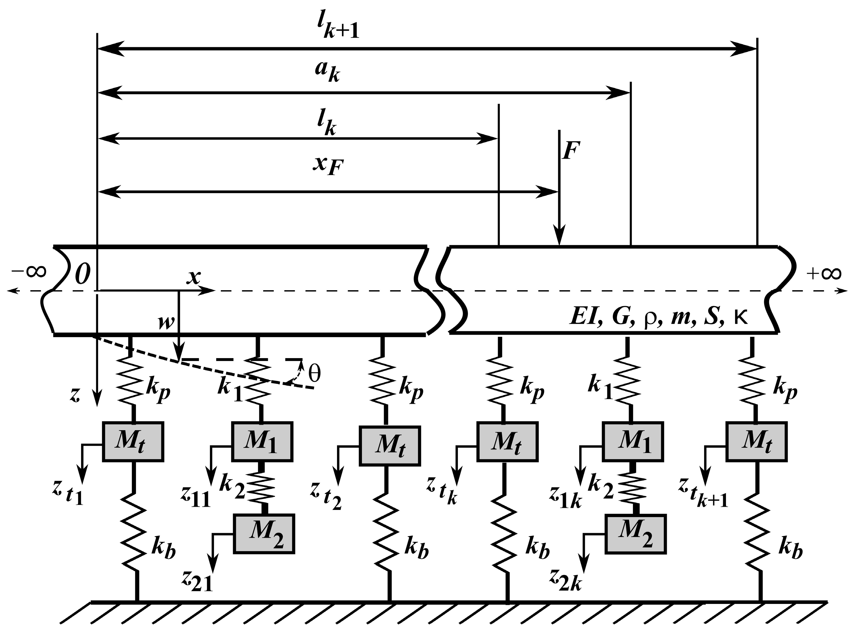
The model of the ballasted track featured with rail dampers, reduced to a rail with rail dampers due to track longitudinal symmetry, is shown in Figure 1.

Figure 1.
The model of the rail featuring rail dampers.
The rail is assimilated with an infinite uniform Timoshenko beam placed on punctual equidistant support consisting of a viscoelastic element (rail pad), a rigid body in vertical translation (sleeper), and another viscoelastic element attached to the rigid base to model the ballast.
The rail dampers are represented using oscillating systems with two degrees of freedom that are connected to the rail in the middle of the distance between the sleepers.
Parameters for the track model are as follows:
- -
- For the rail: E and G—the Young and shear moduli of elasticity; m and ρ—the mass per unit length and density; S and I—the cross-section area and moment of inertia; and κ—the shear coefficient.
- -
- For the rail support: Ms–the semi-sleeper mass; kp,b—the stiffness of the rail pad and ballast; and lk—the position of the k rail support.
- -
- For the rail damper (a pair for each sleeper bay): M1,2—the mass of the rail damper bodies; k1,2—the stiffness of rubber elements; and ak—the position of the k rail damper.
Considering the steady-state harmonic behavior of angular frequency , equations of motion can be written as follows:
- -
- For the rail:
- -
- For the sleeper ‘k’:
- -
- For the rail damper ‘k’:
Using the complex stiffnesses in Equations (1)–(3), the hysteretic damping is introduced into the model as follows:
where i2 = –1, ηp,b, and η1,2 are the loss factors for the rail pad, ballast, and rail damper, respectively.
The rail loss factor, η, is considered in Equation (1) using the following notations:
The boundary conditions should be associated with the rail equations of motion as follows:
Applying the convolution theorem, the rail displacement in section x due to the harmonic force of angular frequency ω applied in section xF results in the following:
where gT(x, ξ, ω) is the frequency–domain Green function associated with the rail equations
with g(x, ξ, ω) being the frequency–domain Green function associated with the infinite Timoshenko beam
where β1,2 depend on the angular frequency as follows:
The complex stiffnesses in Equation (7) are as follows:
By performing the integral in Equation (7), it obtains the following:
Complex amplitude of the rail in lk and ak is needed to calculate the complex amplitude of the rail in the x section. To this end, it writes the following:
where the index k has been replaced by n in sums.
Considering the boundary condition (5), the complex amplitude of the rail is negligible when the distance between the support k and the xF section of the harmonic force is large. Consequently, Equation (13) can be reduced to a set of 2N − 1 equations and reorganized using the following matrix form:
where
and
By solving Equation (14) numerically, the complex amplitude of the rail at lk, 1≤k≤N and ak, 1≤k≤N−1 is obtained, and then the complex amplitude of the rail in the x section can be calculated:
The above approach is like the one applied in ref. [20], where a free–free Timoshenko beam with two degrees of freedom oscillator was used to build the model of a finite-length rail with rail damper discretely elastically supported at both ends that has been subject to experimental tests. Parameters of the rail damper model (two degrees of freedom oscillator) have been determined by comparing the theoretical and experimental results in terms of the rail receptance.
To calculate TDR for a particular one-third octave band of the central angular frequency ωc, a spatial partition, x0, x1, …, xS, of constant step, Δx = xi+1 − xi, where i = 0 ÷ S − 1, is needed, and then the following formula should be applied:
where w2(xi,wc) is the mean square rail amplitude associated with the angular frequency
where ωi,s are the limits of the one-third octave band and Δω is its width (Δω = ωs − ωi), and is the complex conjugate of the complex amplitude .
Numerically, the mean square rail amplitude can be calculated applying the trapezoidal method:
where ω0 = ωi, ωN = ωs, and ωj+1 − ωj = Δω/N with 0 ≤ j ≤ N − 1.
3. Numerical Application
This section studies how rail dampers influence the dynamic response of the rail and the track decay rate based on the results obtained with the mechanical model shown above.
Table 1 contains the parameter values of the track and rail dampers model.

Table 1.
Track and rail dampers model parameters.
It is about a ballasted track provided with a type 49 rail and concrete sleepers with the sleeper bay between 544 and 595 mm in accordance with the CFR regulations. Two values of the stiffness of the rail pads for soft and stiff rail pads are considered, respectively, as well as two values of the stiffness of the ballast for tampered (low stiffness) and settled ballast (high stiffness). Rail damper parameters have been obtained based on the experimental test performed using the impact hammer technique to determine the rail receptance of a setup consisting of a rail of finite length with rail damper and on the numerical results derived from the model of the setup [20].
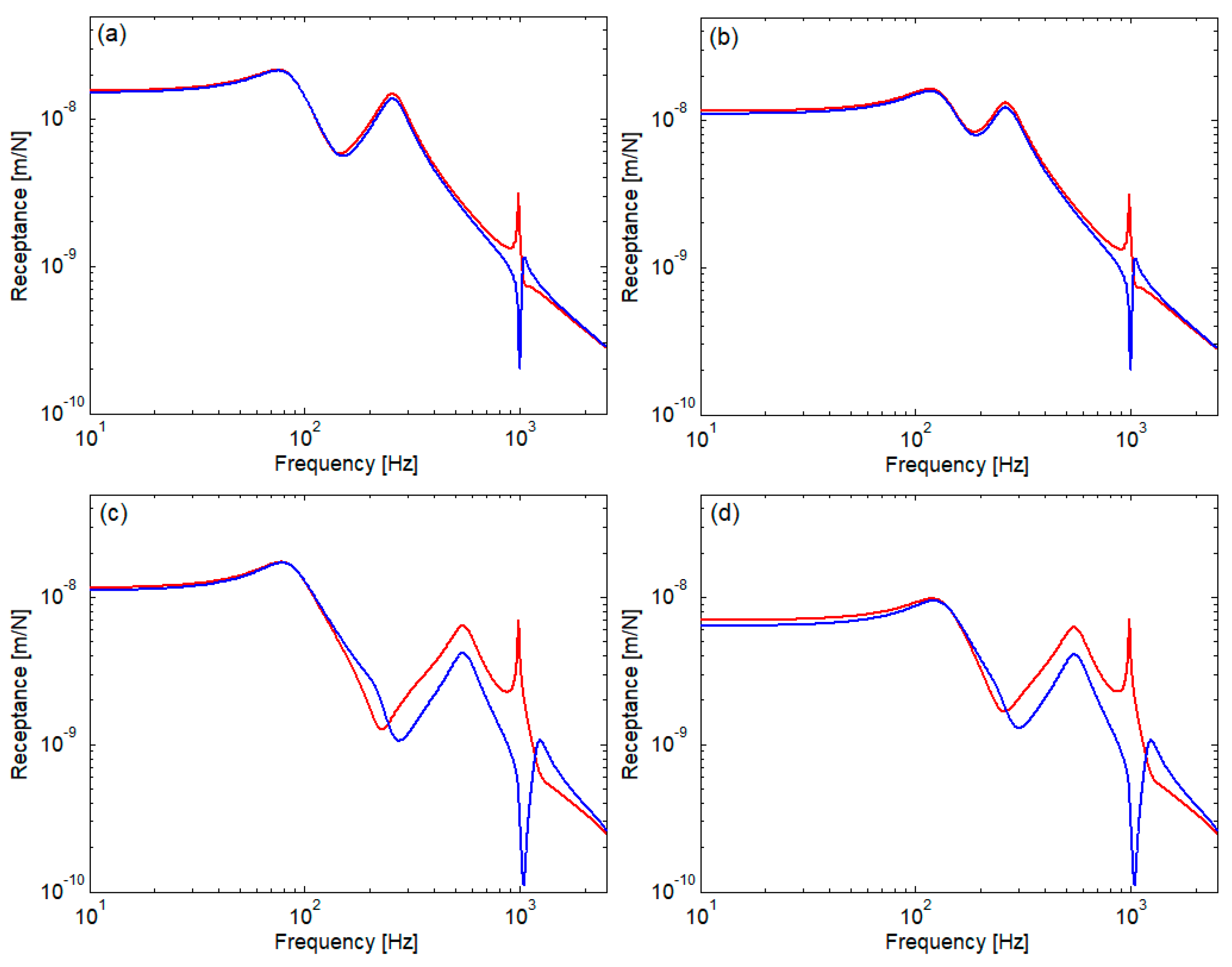
First, the main characteristic of the rail response is analyzed using the receptance diagrams as depicted in Figure 2. There are four combinations between the rail pad stiffness and ballast stiffness: soft/stiff rail pad with tampered/settled ballast; the sleeper bay is 0.544 m. Rail receptance is calculated either halfway between the sleepers or above a sleeper on the interval between 10 Hz and 2500 Hz with the step of 1 Hz. The section of the harmonic force coincides with the calculation section in both situations. At low and medium frequencies, the response of the rail resembles that of an elastic system with two degrees of freedom. Two local maxima of rail receptance are observed between which there is a local minimum. The two maxima correspond to the low and high resonance frequencies of the rail and the sleepers vibrating together on the rail pads and on the ballast prism. The local minimum of the rail receptance shows an anti-resonance behavior due to the dynamic absorb effect that the sleepers play in relation to the rail. At high frequency, there is a peak in the rail receptance diagram calculated between sleepers due to the resonance of the pinned–pinned mode of the rail and a deep (anti-resonance) peak when the rail receptance is calculated above a sleeper. The low frequency of resonance is mainly influenced by ballast stiffness, and the high frequency of resonance is determined by the rail pad stiffness. The frequency of pinned–pinned mode is determined by the rail features and the sleeper bay. At low frequencies, below the low resonance, the rail receptance is little influenced by the frequency because the vibration behavior is dominated by the elastic force, which is frequency independent. At high frequency, beyond the pinned–pinned resonance, the rail receptance decreases because the inertia force is prevalent and the rail has the tendency to vibrate independently. This happens until the next rail bending mode occurs, but its resonance frequency is much higher, and it is not captured in diagrams.
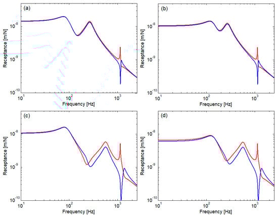
Figure 2.
Rail receptance for the sleeper bay of 0.544 m: (a) kp = 60 MN/m, kb = 40 MN/m; (b) kp = 60 MN/m, kb = 100 MN/m; (c) kp = 300 MN/m, kb = 40 MN/m; and (d) kp = 300 MN/m, kb = 100 MN/m; ―, between sleepers; ―, above sleeper.
Table 2 presents the main frequencies mentioned above for each case. The soft/stiff rail pad determines the high resonance around 265/562 Hz, independent of the ballast stiffness. The tampered/settled ballast gives the low resonance around 79.5/124.5 Hz, whatever the rail pad stiffness. The anti-resonance frequency depends on the position along the rail. The pinned–pinned resonance occurs around 1135.5 Hz for any case considered.
Table 2.
Main frequencies characterizing the rail response for sleeper bay of 0.544 m.
Figure 3 shows the rail receptance for the sleeper bay of 0.595 m, considering the same cases, and Table 3 encompasses the main frequencies. Compared to the preceding case (sleeper bay of 0.544 m), the main frequencies are a little lower (the decrease is smaller than 4.10%) because the stiffness of the rail support per unit length decreases. The pinned–pinned frequency lowers with 13.5% because the wavelength of the bending wave increases from 2 × 0.544 m to 2 × 0.595 m; at pinned–pinned frequency, the wavelength is twice as long as sleeper bay. Rail receptance is higher when the sleeper bay is 0.595 m because the equivalent stiffness per unit length of the rail pads and ballast is smaller.
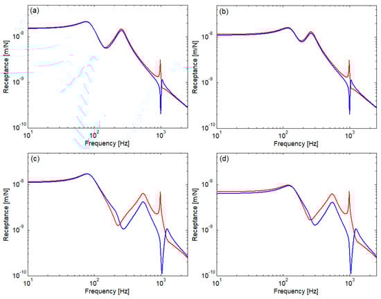
Figure 3.
Rail receptance for the sleeper bay of 0.595 m: (a) kp = 60 MN/m, kb = 40 MN/m; (b) kp = 60 MN/m, kb = 100 MN/m; (c) kp = 150 MN/m, kb = 40 MN/m; and (d) kp = 150 MN/m, kb = 100 MN/m; ―, between sleepers; ―, above sleeper.
Table 3.
Main frequencies characterizing the rail response for sleeper bay of 0.595 m.
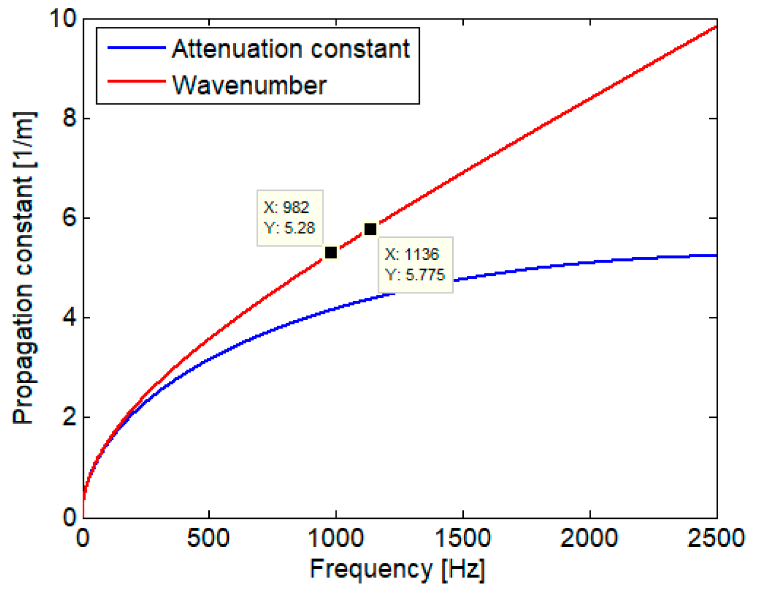
Second, the bending waves in rail are analyzed. Equation (9) shows that two kinds of bending waves propagate along the infinite rail without supports: a propagative wave with the wavenumber β2 and an evanescent wave with attenuation constant β1; both waves can be progressive and regressive. Figure 4 presents the propagate constants for the two kinds of waves. Both propagate constants increase monotonically within the frequency interval considered (0–2500 Hz), which means that the wavelength of the propagative wave lowers, and the attenuation constant of the evanescent wave increases continually as the frequency increases. The two wavenumber values displayed on the diagram are associated with the pinned–pinned frequencies; each wavelength equals the corresponding double sleeper bay.
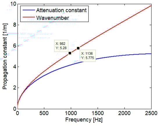
Figure 4.
Propagation constants (η = 0).
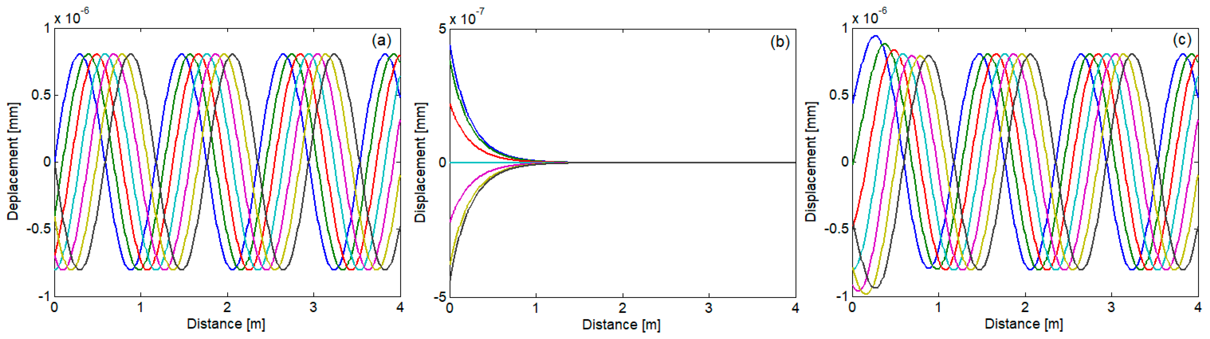
Figure 5 illustrates the bending waves through the rail without support at the frequency of 1000 Hz represented at the time moments t = 0, t = T/12, t = 2T/12, t = 3T/12, t = 4T/12, t = 5T/12, and t = 6T/12, where T is the period (T = ω/(2π)). In a propagative wave (Figure 5a), all points move with the same amplitude due to the lack of damping but with a delay as the wave reaches each point. In an evanescent wave (Figure 5b), all points move in phase, but the amplitude is exponentially decreasing. The bending wave is influenced by the evanescent wave only in the near field, and then it basically becomes a pure propagative wave (Figure 5c).
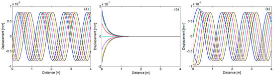
Figure 5.
Bending wave of 1000 Hz in the rail without supports (η = 0): (a) propagative wave; (b) evanescent wave; and (c) bending wave: ―, t = 0; ―, t = T/12; ―, t = 2T/12; ―, t = 3T/12, ―, t = 4T/12, ―, t = 5T/12, ―, t = 6T/12.
Rail support does not change the nature of the two waves but modifies their mode of manifestation according to the main frequencies.
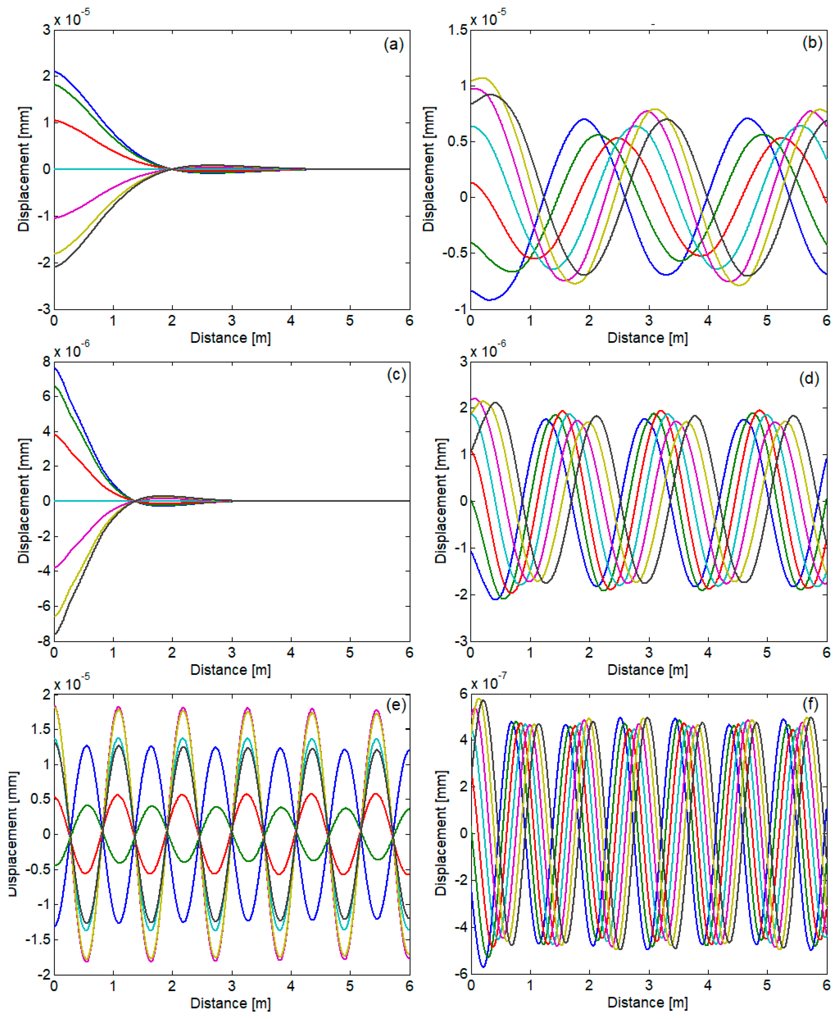
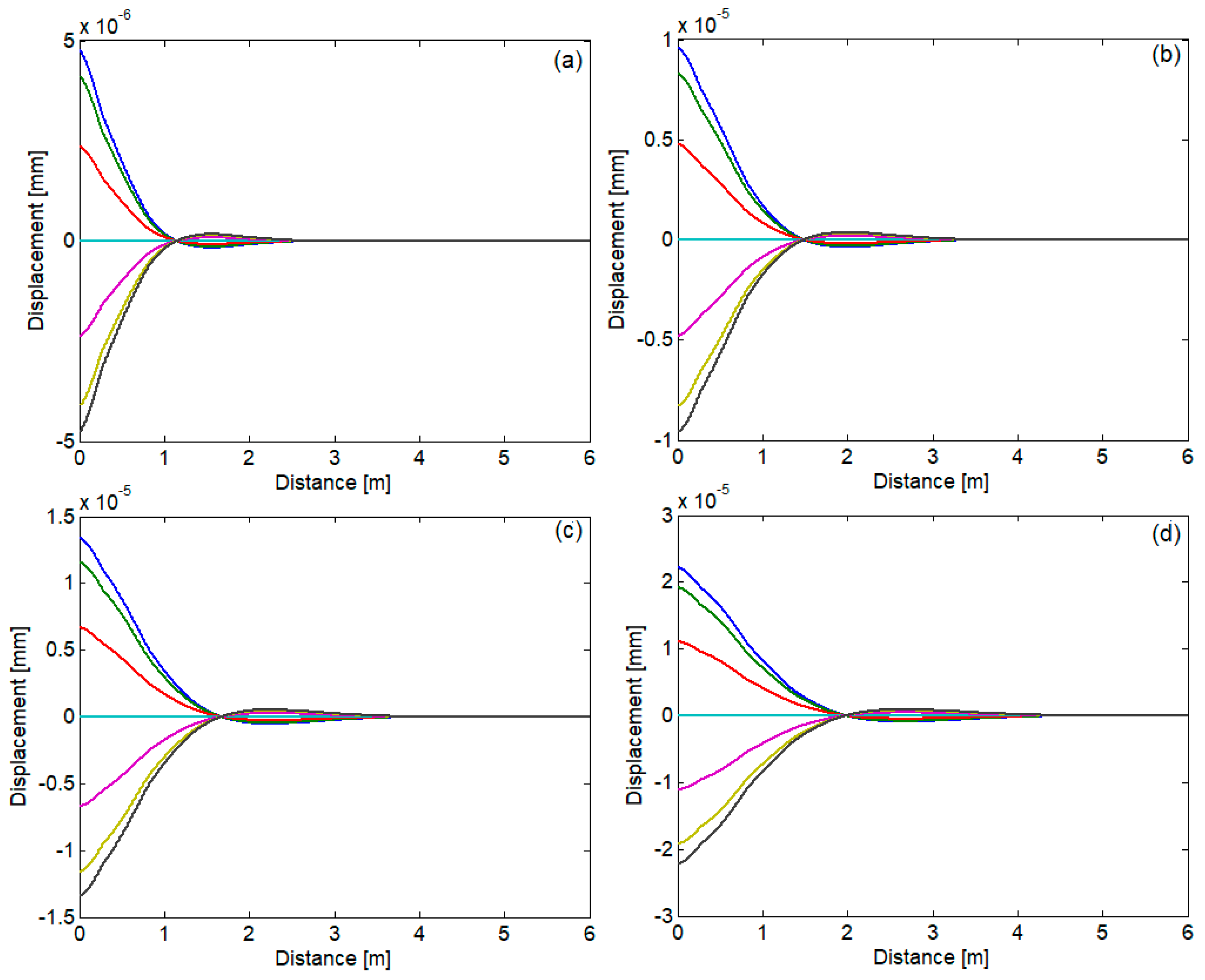
For instance, Figure 6 shows the bending waves in the rail laid on soft rail pads and tampered ballast when the sleeper bay is 0.544 m, considering the following frequencies: 50 Hz, 110 Hz, 185 Hz, 600 Hz, 1135 Hz, and 1500 Hz; no damping is considered.
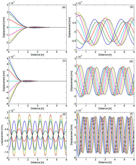
Figure 6.
Bending wave in the rail on soft rail pads and tampered ballast: (a) at 50 Hz; (b) at 110 Hz; (c) at 185 Hz; (d) at 600 Hz; (e) at 1135 Hz; and (f) at 1500 Hz; ―, t = 0; ―, t = T/12; ―, t = 2T/12; ―, t = 3T/12, ―, t = 4T/12, ―, t = 5T/12, ―, t = 6T/12.
The frequencies are chosen so that each one is in one of the frequency ranges delimited by the main frequencies. The bending wave can take the form of attenuated standing wave (Figure 6a,c) or the form of standing wave (Figure 6e). On the other hand, the bending wave can be dominated by a propagative wave (Figure 6b,d,f).
These features of the bending waves outlined above for a few frequencies do not change within a particular range of frequencies delimitated by the main frequencies, as can be seen in Figure 7, where the bending waves for four frequencies between the anti-resonance and the high resonance are displayed as examples.
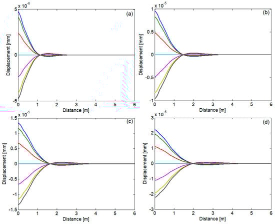
Figure 7.
Bending wave in the rail on soft rail pads and tampered ballast within the range delimited by the anti-resonance and the high resonance: (a) at 160 Hz; (b) at 200 Hz; (c) at 220 Hz; and (d) at 240 Hz; ―, t = 0; ―, t = T/12; ―, t = 2T/12; ―, t = 3T/12, ―, t = 4T/12, ―, t = 5T/12, ―, t = 6T/12.
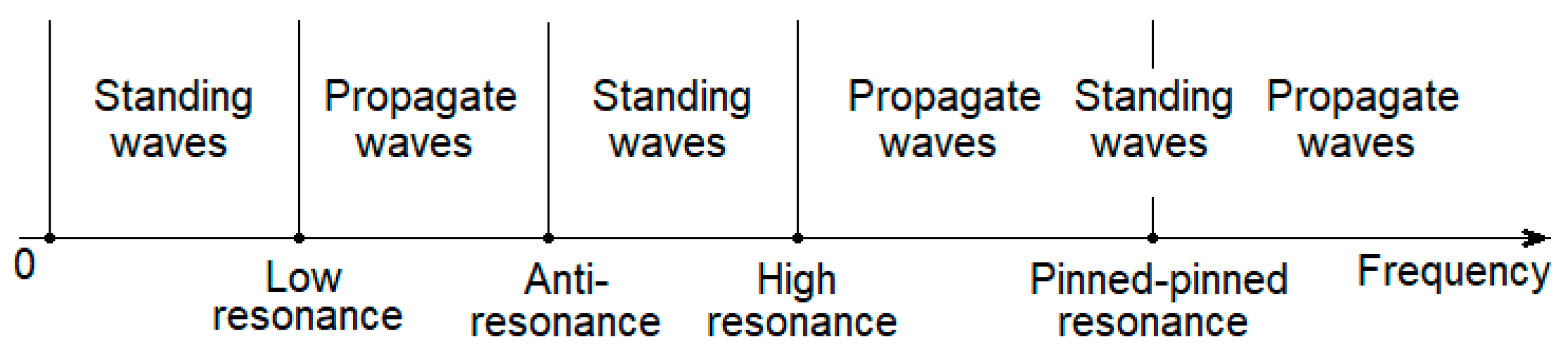
Figure 8 shows the features of the bending waves in rail depending on the frequency ranges delimited by the main frequencies of the track. The rail experiences standing waves within two ranges, namely, at frequencies lower than the low resonance and between the anti-resonance and the high resonance, and also around the pinned–pinned resonance. On the other hand, the bending waves in rail are dominated by the propagative wave when the frequency is within the range between the low resonance and the anti-resonance or within the range that stretches from the high resonance to near the pinned–pinned resonance, or its frequency is higher than the pinned–pinned resonance.
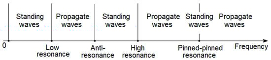
Figure 8.
Features of the bending waves in rail.
Third, TDR for the track without rail dampers is analyzed. TDR is influenced by how the evanescent and propagate waves manifest in the different frequency ranges. Figure 9 presents TDR calculated for one-third octave bands between 100 and 2000 Hz considering spatial partitions with the step of 1/32 sleeper bay, with the active section above the sleeper and between sleepers (at middle).
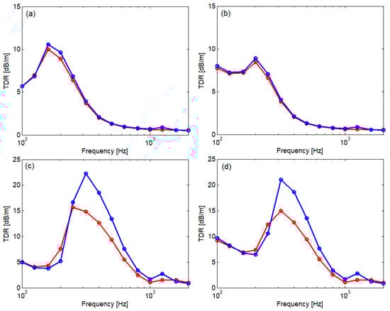
Figure 9.
TDR for track without rail dampers (sleeper bay of 0.544 m): (a) kp = 60 MN/m, kb = 40 MN/m; (b) kp = 60 MN/m, kb = 100 MN/m; (c) kp = 300 MN/m, kb = 40 MN/m; and (d) kp = 300 MN/m, kb = 100 MN/m; ―, between sleepers; ―, above sleeper.
In general, all diagrams of TDR have a peak beyond the anti-resonance, within the second frequency range of the standing waves, between the anti-resonance and the high resonance. This peak corresponds to the one-third octave of 160 Hz/200 Hz for soft rail pad and tampered/settled ballast and to the one-third octave of 315 Hz for stiff rail pad. The value of this peak is higher in the case of stiff rail pads because the propagation of the bending waves is obstructed by the stronger coupling between the rail and the sleepers. The second local peak is more visible when the excitation point is situated between sleepers and it appears around the pinned–pinned resonance where the bending waves in rail are also standing waves, corresponding to the one-third octave of 1250 Hz. This time, the TDR peak is much smaller due to the pinned–pinned resonance. When the propagation of the bending waves is dominated by the propagative wave, TDR decreases to low values, as it happens beyond the high frequency and then, beyond the pinned–pinned resonance, where the rail vibration tends to be independently from the sleepers’ vibration. However, the rail–sleepers coupling leads to higher TDR in the case of the stiff rail pads.
When the ballast is settled, this results in an increased TDR at low frequency, where the ballast stiffness matters. Higher ballast stiffness limits the sleepers’ motion and then the propagation of the rail’s bending waves. All diagrams in Figure 9 show that TDR is lower when the harmonic force acts above sleeper. This can be explained by the fact that the distance between the section of the harmonic force and the first sleeper is twice as high and the bending waves travel ‘freely’ more time until the first point of reflection. Higher coupling between the rail and sleepers due to stiff rail pad increases the difference between the two cases (Figure 9c,d).
Figure 10 presents TDR calculated in the same conditions as above, excepting the sleeper bay that is 0.595 m in this case. TDR diagrams look like the ones above, showing the same main characteristics. The highest TDR peak is located within the second range of the standing wave: within the one-third octave of 160 Hz for the track with soft rail pads–tampered ballast, within the one-third octave of 200 Hz for the track with soft rail pads–settled ballast, and within the one of 315 Hz for the track with stiff rail pads and for any condition of the ballast. The second TDR peak is signaled within the one-third octave of 1 kHz that corresponds to the pinned–pinned resonance from 982 Hz. Also, TDR decreases within the frequency ranges where the bending waves become propagative waves. However, the comparison between Figure 9 and Figure 10 shows that the larger sleeper bay lowers TDR because the bending waves travel ‘freely’ a longer distance from one reflection point to another.
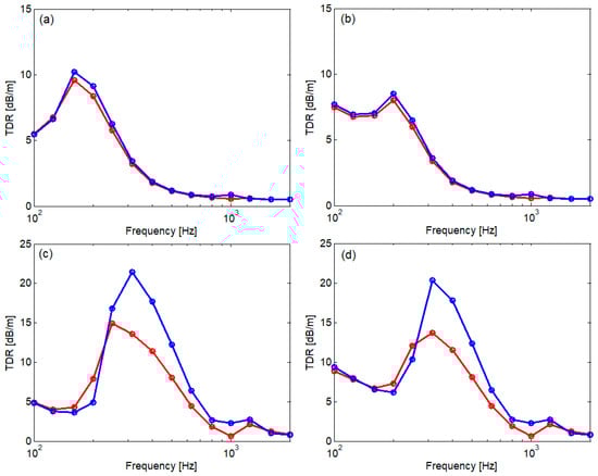
Figure 10.
TDR for track without rail dampers (sleeper bay of 0.595 m): (a) kp = 60 MN/m, kb = 40 MN/m; (b) kp = 60 MN/m, kb = 100 MN/m; (c) kp = 300 MN/m, kb = 40 MN/m; and (d) kp = 300 MN/m, kb = 100 MN/m; ―, between sleepers; ―, above sleeper.
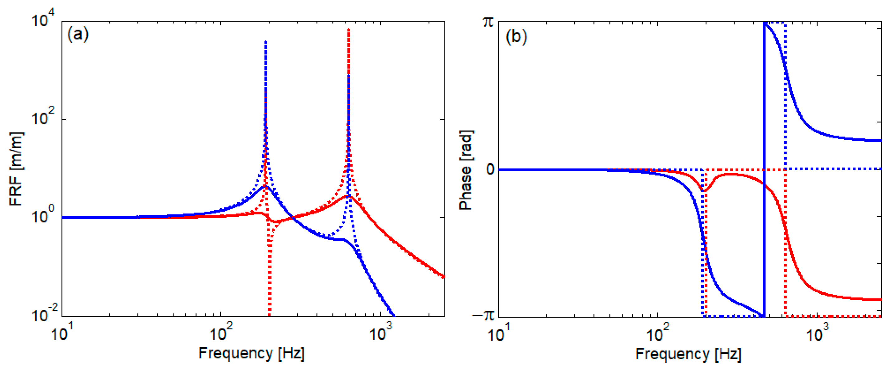
Finally, the influence of the rail dampers is analyzed. Figure 11 displays the transfer functions of the rail damper (moduli and phases with/without damping) calculated as a ratio between the displacement of the masses 1 and 2, respectively, and the rail displacement, considered the following harmonic function:
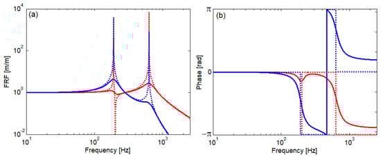
Figure 11.
Frequency response function of the rail damper’s masses: (a) modulus and (b) phase. ―, mass 1 with damping; ····, mass 1 without damping; ―, mass 2 with damping; ····, mass 2 without damping.
Rail damper has two resonance frequencies, at 190 Hz and 628 Hz, and mass 1 exhibits anti-resonance behavior at 201 Hz. When the rail frequency is around the first resonance of the rail damper, the vibration of mass 1 is lower than the mass 2 vibration, which is out of phase with the rail displacement. Consequently, the second elastic element of the rail damper dissipates more energy. When the rail frequency is around the second resonance and beyond this, the vibration of the mass 1 becomes higher, and it is out of phase with the rail displacement and the mass 2 of the rail damper. This time, the first elastic element dissipates more energy than the second one.
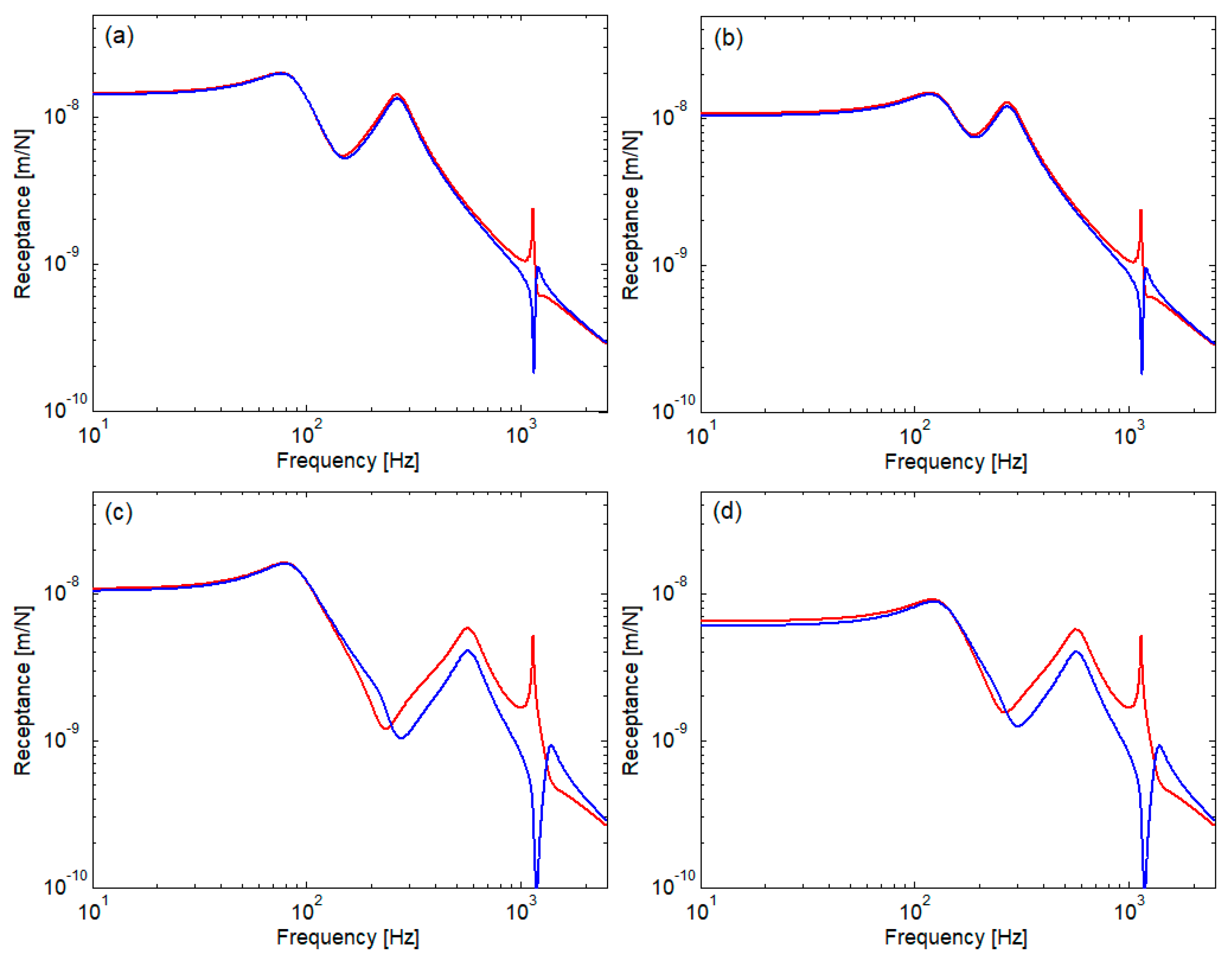
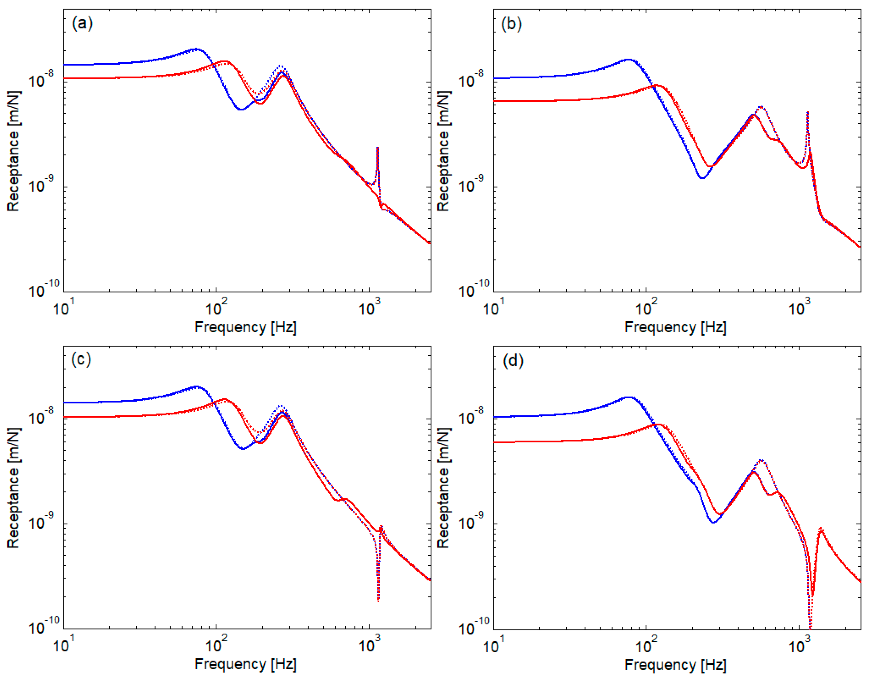
Figure 12 shows the comparison between the track without rail dampers and the track with rail dampers in terms of the rail receptance calculated between sleepers (Figure 12a,b) and above sleepers (Figure 12c,d), considering the sleeper bay of 0.544 m and all four cases regarding the stiffness of the rail pad and ballast. Rail damper modifies the rail receptance and becomes effective beyond the anti-resonance frequency for soft rail pads (Figure 12a,c) and beyond the high resonance for stiff rail pads (Figure 12b,d); it works practically independently by the ballast condition. Rail damper reduces the rail receptance around the high resonance and within the second range of the propagative wave and narrows the difference between the pinned–pinned peak and the depth of the receptance calculated above sleeper, especially when the rail pads are soft (Figure 12a,c).
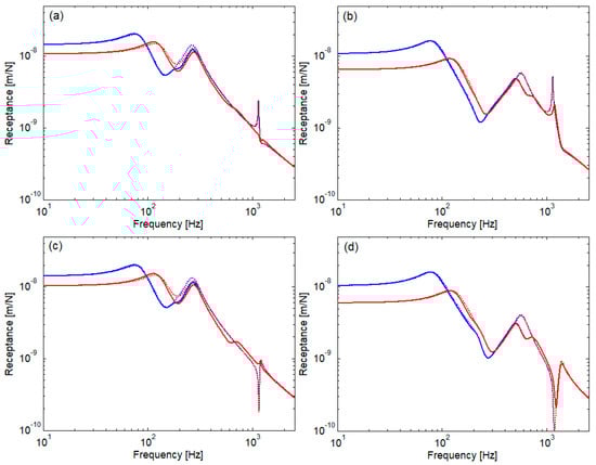
Figure 12.
Rail receptance for track without/with rail dampers (sleeper bay of 0.544 m): (a) between sleepers, kp = 60 MN/m; (b) between sleepers, kp = 300 MN/m; (c) above sleepers, kp = 60 MN/m; and (d) above sleepers, kp = 300 MN/m; ····, kb = 40 kM/m, without rail dampers; ―, kb = 40 kM/m, with rail dampers; ····, kb = 100 kM/m, without rail dampers; ―, kb = 100 kM/m, with rail dampers.
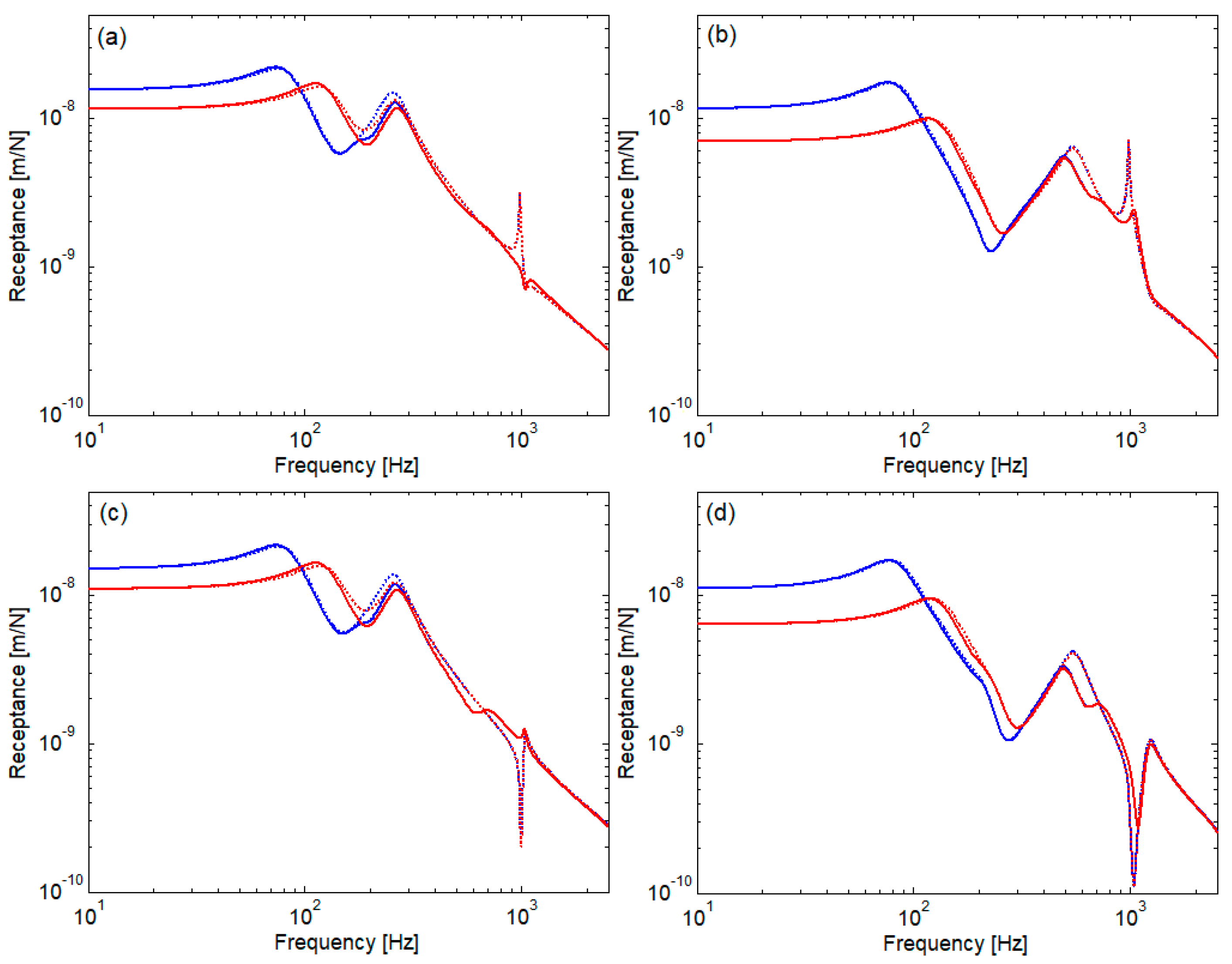
Figure 13 presents what happens with the rail receptance of a track without/with rail dampers when the sleeper bay is 0.595 m. The influence of the rail dampers upon the rail receptance is similar to one of the preceding cases. Certainly, the rail receptance is higher due to the reason mentioned above (see Figure 3). Rail damper also levels the rail receptance around the pinned–pinned resonance, but in a range located at lower frequencies because the frequency of this resonance is lower (982 Hz vs. 1135 Hz, see Table 2 and Table 3).
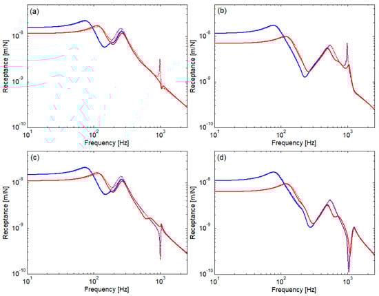
Figure 13.
Rail receptance for track without/with rail dampers (sleeper bay of 0.595 m): (a) between sleepers, kp = 60 MN/m; (b) between sleepers, kp = 300 MN/m; (c) above sleepers, kp = 60 MN/m; and (d) above sleepers, kp = 300 MN/m; ····, kb = 40 kM/m, without rail dampers; ―, kb = 40 kM/m, with rail dampers; ····, kb = 100 kM/m, without rail dampers; ―, kb = 100 kM/m, with rail dampers.
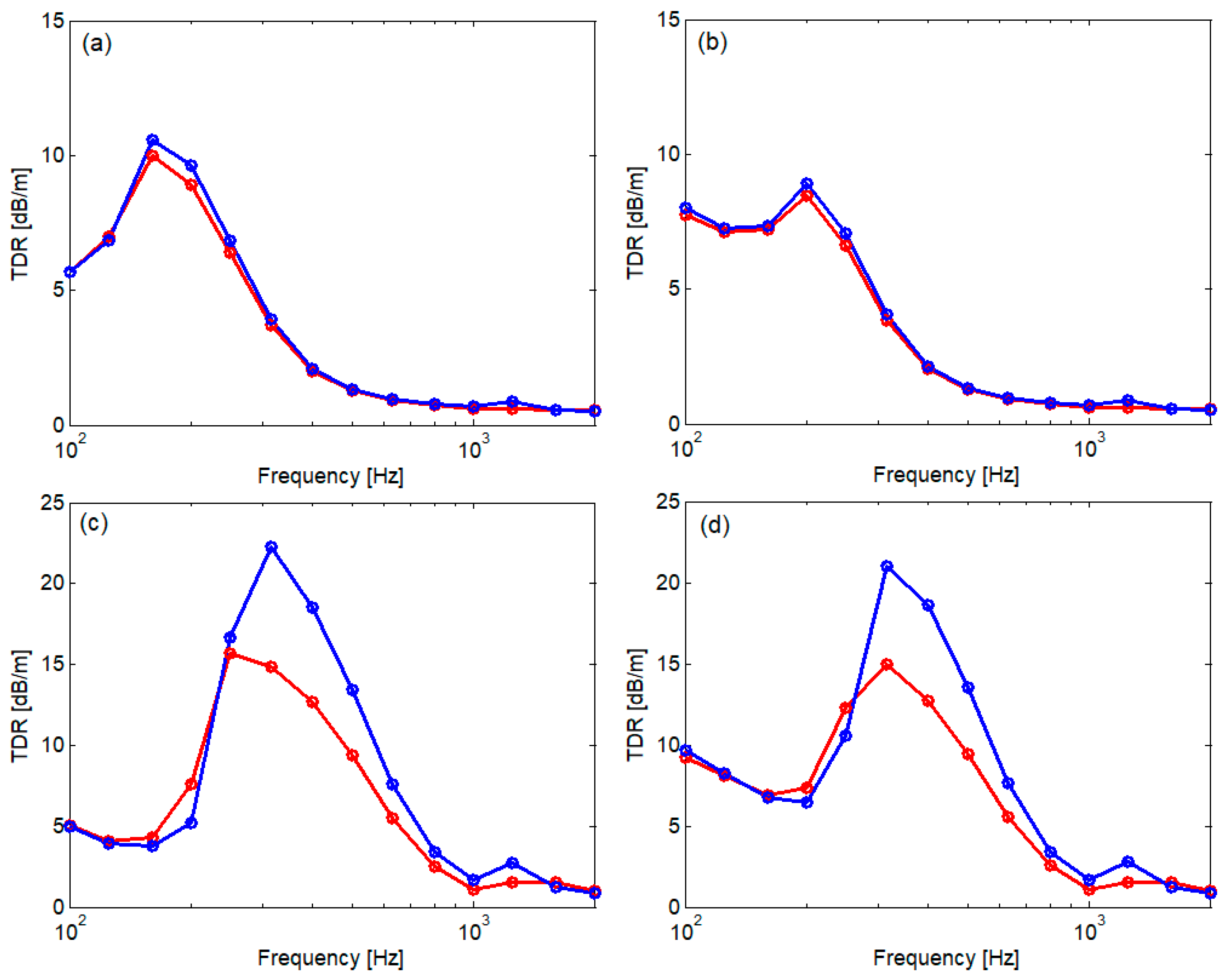
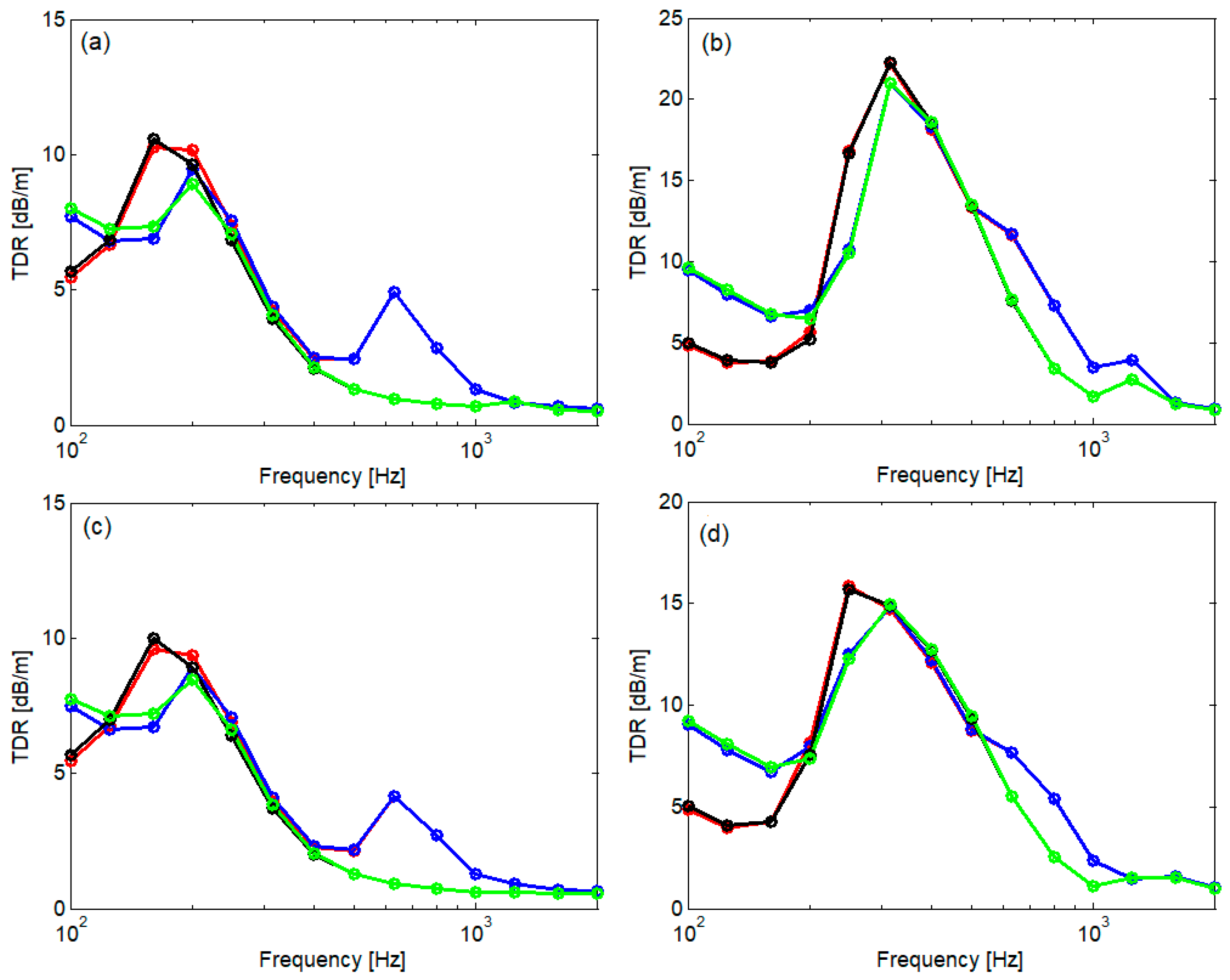
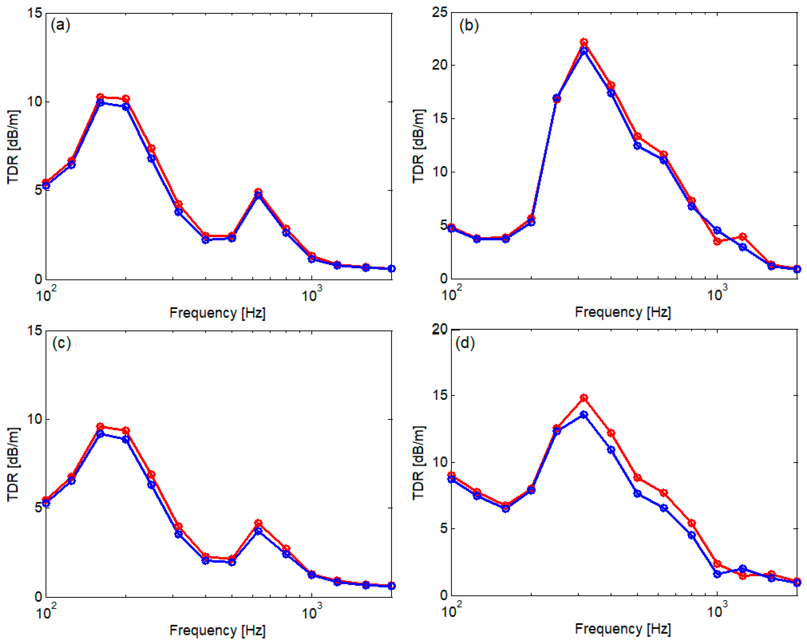
Figure 14 shows the comparison between the track without rail dampers and the track with rail dampers in terms of TDR calculated when the excitation point is between sleepers (Figure 14a,b) and above sleepers (Figure 14c,d). Soft/stiff rail pads and tampered/settled ballast have been considered. The influence of the rail dampers upon TDR does not depend on the ballast condition. For track with soft rail pads, the rail dampers work between 400 and 1250–1600 Hz, while for a track with stiff rail pads, the rail dampers are effective within a range that starts at over 500 Hz and reach the same superior limit. The highest TDR increase occurs when the excitation point is between sleepers: 3.93 dB/m for soft rail pads and 4.09 dB/m for stiff rail pads. When the excitation force acts above sleepers, the TDR increase is 3.2 dB/m for soft rail pads and 2.86 dB/m for stiff rail pads.
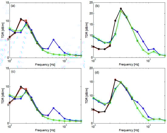
Figure 14.
TDR for track without/with rail dampers (sleeper bay of 0.544 m): (a) between sleepers, kp = 60 MN/m; (b) between sleepers, kp = 300 MN/m; (c) above sleepers, kp = 60 MN/m; and (d) above sleepers, kp = 300 MN/m; ―, ―, kb = 40 MN/m; ―, ―, kb = 100 MN/m; ―, ―, without rail dampers; ―, ―, with rail dampers.
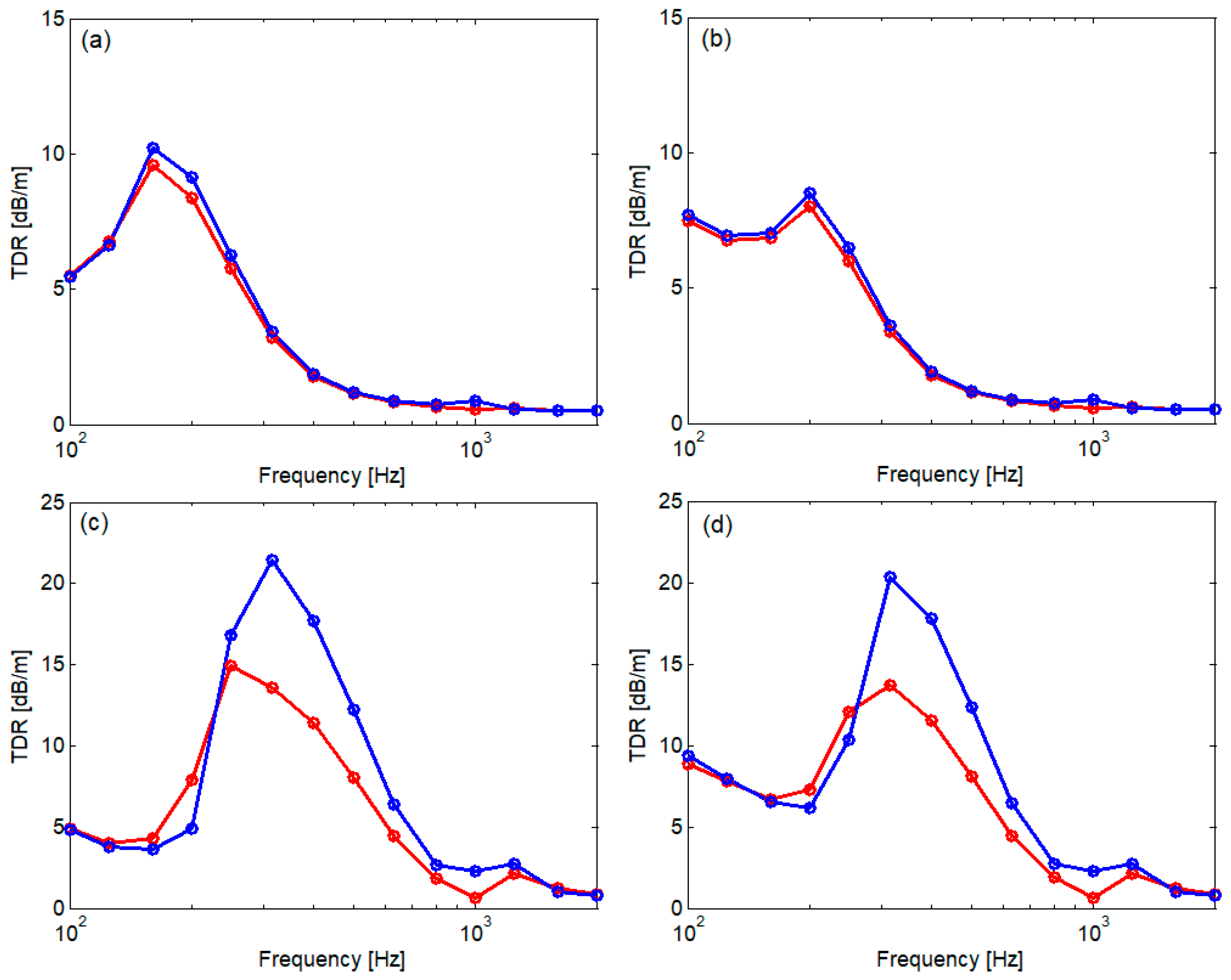
Figure 15 shows what happens when the distance between sleepers becomes 0.595 m by comparing to the case of sleeper bay of 0.544 m. It considers only the track with tampered ballast and rail dampers. In general, the TDR has a slight decrease when the length between sleepers is longer, especially in the case of the stiff rail pad when the excitation point is above sleepers.
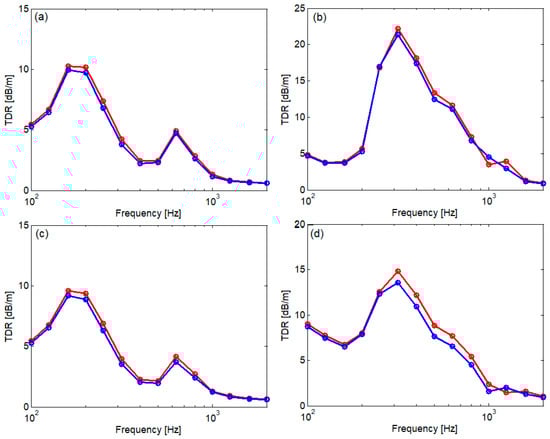
Figure 15.
Illustrative for the influence of the sleeper bay enlargement from 0.544 m to 0.595 m (kb = 40 MN/m): (a) between sleepers, kp = 60 MN/m; (b) between sleepers, kp = 300 MN/m; (c) above sleepers, kp = 60 MN/m; and (d) above sleepers, kp = 300 MN/m; ―, track with rail dampers and sleeper bay of 0.544 m; ―, track with rail dampers and sleeper bay of 0.595 m.
4. Conclusions
The rail damper is a mechanical tool that is mounted on the rail to reduce the propagation of bending waves along it. Considering this, the rail damper is a means of reducing the noise produced by the rail.
In this paper, a parametric study on the influence of the rail damper with mixed damping system upon the dynamic response of the light rail and rail damper effectiveness in terms of the receptance and TDR, respectively, was carried out. This study is based on a continuous–discrete model in which the rail is an infinite Timoshenko beam, and the elastic supports, including rail pad, sleeper, and ballast, and the rail dampers are made up of elements with concentrated parameters. The rail receptance and TDR were calculated using the frequency–domain Green’s function associated with the Timoshenko differential operator. Four scenarios were taken regarding the condition of the rail pads (soft/stiff) and the ballast (tampered/settled), considering two values for the distance between the sleepers (short/long).
The main frequencies that characterize the dynamic response of the rail, the low/high resonance, the anti-resonance and pinned–pinned resonance, and the shape of the bending waves that propagate along the rail (standing/propagative waves) have been outlined. The low/high resonance frequencies are mostly determined by the ballast/rail pad stiffness, while the pinned–pinned resonance depends on the rail features and the sleeper bay.
TDR is higher in the case of the track featured with stiff rail pads in comparison to the track with soft rail pads.
The rail receptance decreases around the second resonance and within the second propagative wave range when the rail is fitted with rail dampers. The difference between the receptance of the rail in the midspan and the one above sleepers around the pinned–pinned resonance is diminished by the presence of rail dampers.
Using rail dampers with a mixed damping system, TDR can increase at middle and high frequencies, from 4 to 500 Hz up to 1250–1600 Hz, for both soft and stiff rail pads, independent of the ballast condition. TDR increasing depends on the position of the excitation force, and it is higher when the force position is between sleepers. Larger sleeper bay, lower TDR for both tracks without/with rail dampers.
Author Contributions
Conceptualization, T.M. and D.F.; methodology, T.M. and D.F.; software, T.M., D.F. and M.-A.G.; validation, T.M.; formal analysis, T.M. and I.-I.A.; investigation, T.M. and D.F.; resources, D.F., M.-A.G. and I.-I.A.; data curation, D.F.; writing—original draft preparation, D.F.; writing—review and editing, T.M.; visualization, T.M. and D.F.; supervision, T.M.; project administration, T.M.; funding acquisition, T.M. All authors have read and agreed to the published version of the manuscript.
Funding
The second, third, and fourth authors declare that their work was supported by a grant from the National Program for Research of the National Association of Technical Universities–GNAC ARUT 2023, contract No. 154/04.12.2023.
Institutional Review Board Statement
Not applicable.
Informed Consent Statement
Not applicable.
Data Availability Statement
The original contributions presented in this study are included within the article; further inquiries can be directed to the corresponding authors.
Conflicts of Interest
The authors declare no conflicts of interest.
References
- Hemsworth, B. Environmental Noise Directive Development of Action Plans for Railways, Prepared for International Union of Railways. 2008. Available online: https://uic.org/IMG/pdf/action_planning_paper_final-2.pdf (accessed on 16 October 2024).
- Remington, P.J. Wheel/rail rolling noise: What do we know? What don’t we know? Where do we go from here ? J. SoundVib. 1988, 120, 203–226. [Google Scholar] [CrossRef]
- Thompson, D. Railway Noise and Vibration Mechanisms, Modelling and Means of Control; Elsevier: Oxford, UK, 2009. [Google Scholar]
- Andrés, V.T.; Martínez-Casas, J.; Denia, F.D.; Thompson, D.J. Influence study of rail geometry and track properties on railway rolling noise. J. Sound Vib. 2022, 525, 116701. [Google Scholar] [CrossRef]
- Sadeghi, J.; Hasheminezhad, A. Correlation between rolling noise generation and rail roughness of tangent tracks and curves in time and frequency domains. Appl. Acoust 2016, 107, 10–18. [Google Scholar] [CrossRef]
- Mihailescu, I.M.; Popa, G.; Oprea, R. Detection of defects in the railway track that can influence traffic safety using the method of vibration analysis of vehicle-rail system. Acta Tech. Napoc. Ser.-Appl. Math. Mech. Eng. 2022, 65, 1241–1248. [Google Scholar]
- Liu, X.; Liu, C.; Wu, W.; Liu, J.Z.; Sun, S.C.; Wai, Y.G. Transient dynamics of a full wheel rail set passing a weld irregularity at high speed. Eng. Fail. Anal. 2023, 148, 107203. [Google Scholar] [CrossRef]
- Mihailescu, I.; Popa, G.; Tudor, E.; Vasile, I.; Gheți, M.A. Experimental Study of Wheel-to-Rail Interaction Using Acceleration Sensors for Continuous Rail Transport Comfort Evaluation. Sensors 2023, 23, 8064. [Google Scholar] [CrossRef]
- Mazilu, T. Interaction between moving tandem wheels and an infinite rail with periodic supports–Green’s matrices of the track method in stationary reference frame. J. Sound Vib. 2017, 401, 233–254. [Google Scholar] [CrossRef]
- Hamet, J.F. Rolling noise: Use of the Timoshenko Model in Rail Vibration Studies. Acta Acust. 1999, 85, 54–62. [Google Scholar]
- Jones, C.J.C.; Thompson, D.J.; Diehl, R.J. The use of decay rates to analyse the performance of railway track in rolling noise generation. J. Sound Vib. 2006, 293, 485–495. [Google Scholar] [CrossRef]
- Ryue, J.; Thompson, D.J.; White, P.R.; Thompson, D.R. Decay rate of propagating waves in railway tracks at high frequencies. J. Sound Vib. 2009, 320, 955–976. [Google Scholar] [CrossRef]
- EN ISO 3095:2013; Acoustics—Railway Applications—Measurement of Noise Emitted by Railbound Vehicles. ISO: Geneva, Switzerland, 2013.
- Liu, H.P.; Wu, T.X.; Li, Z.G. Theoretical modelling and effectiveness study of rail vibration absorber for noise control. J. Sound Vib. 2009, 323, 594–608. [Google Scholar] [CrossRef]
- Dumitriu, M.; Cruceanu, I.C. On the Rolling Noise Reduction by Using the Rail Damper. J. Eng. Sci. Technol. Rev. 2017, 10, 87–95. [Google Scholar] [CrossRef]
- Michalczyk, R.; Brzeziński, K.; Zbiciak, A. Numerical Vibration Response of Railway Track Retrofitted with Single Degree of Freedom Rail Dampers. IOP Conf. Ser. Mater. Sci. Eng. 2019, 661, 2–8. [Google Scholar] [CrossRef]
- Maes, J.; Sol, H. A double tuned rail damper—increased damping at the two first pinned–pinned frequencies. J. Sound Vib. 2003, 267, 721–737. [Google Scholar] [CrossRef]
- Thompson, D.J.; Jones, C.J.C.; Waters, T.P.; Farrington, D. A tuned damping device for reducing noise from railway track. Appl. Acoust. 2007, 68, 43–57. [Google Scholar] [CrossRef]
- Wu, T.X. Effects on short pitch rail corrugation growth of a rail vibration absorber/damper. Wear 2011, 271, 339–348. [Google Scholar] [CrossRef]
- Mazilu, T.; Fologea, D. Experimental study on the performance of a rail damper. IOP Conf. Ser. Mater. Sci. Eng. 2018, 400, 0620186. [Google Scholar] [CrossRef]
- Wu, T.X. On the railway track dynamics with rail vibration absorber for noise reduction, Predicting the effect of temperature on the performance of elastomer-based rail damping devices. J. Sound Vib. 2008, 309, 739–755. [Google Scholar] [CrossRef]
- Poisson, F.; Margiocchi, F. The use of dynamic dampers on the rail to reduce the noise of steel railway bridges. J. Sound Vib. 2006, 293, 944–952. [Google Scholar] [CrossRef]
- Parker, A.; Weber, C. Rail Dampers–The First Australian Field Trial. In Proceedings of the 20th International Congress on Acoustics, ICA 2010, Sydney, Australia, 23–27 August 2010. [Google Scholar]
- Squicciarini, G.; Toward, M.G.R.; Thompson, D.J. Experimental procedures for testing the performance of rail dampers. J. Sound Vib. 2015, 359, 21–39. [Google Scholar] [CrossRef]
- Chen, J.; Liu, W.; Sun, X. Effects of Tuned Rail Damper on Track Dynamic Characteristics Optimization. Procedia Eng. 2017, 199, 1616–1622. [Google Scholar] [CrossRef]
- Ahmad, N.; Thompson, D.J.; Jones, C.J.C.; Muhr, A.H. Predicting the effect of temperature on the performance of elastomer-based rail damping devices. J. Sound Vib. 2009, 322, 674–689. [Google Scholar] [CrossRef]
- Wu, T.X. Attenuating Railway Track Vibration by Rail Absorber for Noise Reduction. Noise Vib. Worldw. 2008, 39, 14–23. [Google Scholar] [CrossRef]
- Wu, T.X.; Liu, H.P. Reducing the rail component of rolling noise by vibration absorber: Theoretical prediction. Proc. IMechE Part F J. Rail Rapid Transit. 2009, 223, 473–483. [Google Scholar] [CrossRef]
- Jin, H.; Zhou, X.; Sun, X.; Li, Z. Decay rate of rail with egg fastening system using tuned rail damper. Appl. Acoust. 2021, 172, 107622. [Google Scholar] [CrossRef]
- Wang, Y.; Dimitrovová, Z.; Yau, J.D. Laboratory Vibration Studies of Metro Tracks Equipped with Tuned Rail Dampers. J. Vib. Eng. Technol. 2023, 11, 2659–2669. [Google Scholar] [CrossRef]
Disclaimer/Publisher’s Note: The statements, opinions and data contained in all publications are solely those of the individual author(s) and contributor(s) and not of MDPI and/or the editor(s). MDPI and/or the editor(s) disclaim responsibility for any injury to people or property resulting from any ideas, methods, instructions or products referred to in the content. |
© 2024 by the authors. Licensee MDPI, Basel, Switzerland. This article is an open access article distributed under the terms and conditions of the Creative Commons Attribution (CC BY) license (https://creativecommons.org/licenses/by/4.0/).