Article

Recovered Foam Impact Absorption Systems

by
Sara Marcelino-Sádaba
*,
Pablo Benito
,
Miguel Ángel Martin-Antunes
,
Pedro Villanueva Roldán
and
Fernando Veiga
Department of Engineering, Public University of Navarra, Los Pinos Building, Arrosadía Campus, E31006 Pamplona, Navarra, Spain
*
Author to whom correspondence should be addressed.
Appl. Sci. 2024, 14(20), 9549; https://doi.org/10.3390/app14209549
Submission received: 30 August 2024 / Revised: 27 September 2024 / Accepted: 16 October 2024 / Published: 19 October 2024

Abstract

:

Featured Application

Reuse of protective materials and textiles in active leisure centers.

Abstract

The use of foam materials in environments where they come into contact with individuals often results in deterioration, necessitating periodic replacements to maintain safety and hygiene standards. Foam, a lightweight, porous plastic formed by aggregated bubbles, possesses excellent impact-absorbing properties; however, its inherent porosity and susceptibility to wear present challenges. This project aims to develop a technological application for repurposing spent polyurethane (PU) foam from leisure facilities into effective impact absorption systems. By focusing on the reuse of deteriorated foam materials, this initiative seeks to minimize environmental impact while leveraging their beneficial technical characteristics. Addressing issues related to foam degradation, this project endeavors to create sustainable solutions by reintegrating spent foam into new systems. This innovative approach promotes sustainability while enhancing safety through the provision of high-quality, impact-resistant elements. Ultimately, this work aims to contribute to environmental conservation and the advancement of effective impact protection measures in leisure facilities.

1. Introduction

The general objective of this research is to develop a technological application for the use of exhausted foam materials or textile elements generated in leisure facilities to convert them into impact absorption systems enabling the reuse of contaminating elements such as textiles and foam in leisure-related applications, where protection against impact and energy absorption when it occurs is key to ensure the safety of the facilities.
The increase in textile consumption and the trend towards fast fashion among consumers have led to a rapid global increase in textile waste in the municipal solid waste (MSW) stream. Worldwide, 75% of textile waste is landfilled, while only 25% is recycled or reused [1]. With respect to waste management, the most common current opinion is to prioritize the reuse of products over the recycling of materials, with landfill disposal being the least desirable option. In the case of textiles and products made of similar materials such as foam, all these alternatives are feasible; however, there is currently a lack of effective techniques for recycling materials [2]. The reuse of these products in their original form is a common practice in domestic waste management [3], but currently, if we analyze the problem from an industrial point of view, we still do not have the capacity to reuse products in their original form. Industrial textile waste is considered “dirty waste” generated from commercial and industrial textile applications.
The expansion of the textile and leisure industry has led to a rapid global increase in textile waste. Many techniques to recycle textile materials are being developed due to the increasing consumption of these materials [4,5,6,7,8]. However, several studies have shown the importance of reusing products based on these materials since, for every kg reused or recycled, textiles save more greenhouse gases than paper, plastic, and glass combined [9].
The increasing need to reduce environmental impact has led to a growing interest in developing methods to repurpose materials that would otherwise be discarded, particularly in industries where materials are in frequent contact with users and undergo significant wear [10]. One such example is the leisure industry, where foams used in jumping pools and other recreational facilities degrade over time, necessitating their periodic replacement to maintain safety and hygiene standards. The challenge lies in finding sustainable ways to reuse or repurpose these materials without resorting to traditional recycling methods, which often involve destroying the material, thereby consuming additional energy and generating further waste [11].
Polyurethane (PU) foam, a widely used material in these environments, presents an opportunity for reuse due to its inherent mechanical properties, particularly its ability to absorb impact energy [12]. This study seeks to explore the potential for repurposing PU foam, specifically focusing on impact absorption systems, which are in high demand across various sectors, including automotive, aeronautics, packaging, and construction [13]. PU foam, formed by an aggregation of bubbles, is a lightweight, porous plastic material known for its shock-absorbing qualities, making it suitable for reuse in applications that require protective elements [14]. However, despite its extensive use and the volumes of waste it generates, there is a lack of viable recycling solutions, particularly in industries where its functionality is diminished due to wear or damage [15]. Other aspects, such as high volumes due to the low density of foams, make the management of such waste difficult, both in terms of logistics and delivery to incineration plants [16].
The selectivity of polyurethane for this research, over other materials such as polystyrene or polyethylene, is due to its unique combination of properties. Unlike other foams, PU foam exhibits excellent flexibility, resilience, and energy absorption capabilities, making it an ideal candidate for impact protection systems [17]. Moreover, PU foam is highly versatile, with different formulations allowing for customization based on specific application requirements, ranging from soft cushioning to more rigid impact protection [18]. This versatility makes polyurethane more adaptable for a broader range of applications compared to other materials, and its widespread use ensures a large amount of waste material available for repurposing [11]. By focusing on polyurethane, this study addresses a significant waste stream while leveraging the material’s technical advantages for reuse in protective systems. Table 1 highlights various types of materials previously applied in impact absorption or protective systems, categorized by material type, common applications, and key properties relevant to impact absorption.
The problem arises from the deterioration of foam over time, especially when used in contact with people in leisure facilities, leading to a need for periodic replacement to ensure safety and maintain aesthetic quality. This waste, primarily consisting of spent polyurethane foam, is often disposed of in landfills, contributing to environmental pollution due to the lack of viable recycling options [26]. Given the substantial volumes of PU foam used across multiple sectors, the potential for reusing this material is vast, provided that appropriate methods are developed to recover and repurpose the foam’s impact absorption capabilities.
The primary objective of this study is to develop a technological application for repurposing spent foam materials and textile elements from leisure facilities into impact absorption systems. This development aims to facilitate the reuse of waste generated within these facilities, thereby reducing global environmental impact by utilizing the materials’ inherent technical characteristics and addressing the specific environmental impact of materials such as polyurethanes. To achieve this objective, this study will proceed in several phases. First, a knowledge base will be established to understand the impact absorption capacity of foam after its lifecycle in leisure systems. This phase will explore its potential reintegration into impact absorption elements, either as part of broken resistant elements or new protections. Subsequently, the behavior foam for developing new anti-impact systems will be explored.
Further phases will focus on enabling the reuse of contaminating elements such as textiles and foam in leisure-related applications, ensuring impact protection and energy absorption to guarantee the safety of the facilities. This study will also promote the use of well-maintained protections to minimize the impact on individuals in the event of a collision, determining safe conditions for protections and developing rapid adaptation methodologies based on these anti-impact materials. Finally, technical solutions will be developed to create alternative impact safety elements through the recycling of materials like PU foam, guided by technical and scientific criteria to ensure effectiveness and sustainability.
This research offers a novel approach by focusing on the reuse of exhausted polyurethane foams from leisure facilities in the development of impact absorption systems. Unlike previous studies that primarily explored the recycling or destruction of foams, this work emphasizes the direct reuse of foams in their original state, taking advantage of their mechanical properties for energy absorption. This study incorporates both experimental and computational modeling techniques, including cube modelization and impact system simulations, to validate the effectiveness of reused materials. By integrating finite element analysis, this research bridges the gap between material reuse and advanced design optimization, presenting a practical, sustainable solution for reducing waste in industries where shock protection is critical. This unique focus on reuse, combined with the absence of extensive recycling processes, distinguishes this study from prior works in the field, offering a new perspective on material conservation and environmental impact reduction.

2. Materials and Methods

2.1. Raw Materials and Processing of the Foam Samples

The material used for the characterization tests is aligned with the objective of this work, which is to evaluate the reuse potential of discarded polyurethane foam cubes from recreational foam pools by analyzing their mechanical properties. The samples used for the tests were extracted from these discarded materials, which represent waste that we intend to reuse for other applications. These cubes represent waste material that we intend to reuse, and their mechanical properties were evaluated to determine their potential for other applications. The foam used for these cubes could be considered a flexible polyurethane that is created through the reaction between polyols and isocyanates. This material offers compressibility and resilience, which contribute to its cushioning properties, making it perfect for installation in cube pools in recreational facilities.
Figure 1 shows a foam cube pool commonly found in recreational facilities, with polyurethane (PU) foam cubes used as protective elements. These cubes, seen scattered throughout the pool, provide impact absorption for individuals engaging in activities such as jumping or falling. The foam cubes in the pool serve as the source of the specimens for this material reuse study, where their mechanical properties were evaluated to assess their suitability for repurposing.
Five specimens were selected for testing to ensure statistical validity and reliability in evaluating the mechanical properties of the polyurethane foam. The five specimens used in the compression test were obtained directly from the original foam cubes, without modifying their geometry. This decision was made to make the evaluation more representative of the recycling process that would be carried out with the original cubes. By maintaining the dimensions of 200 × 200 × 200 mm, the aim is to more faithfully analyze the mechanical properties of the material as it would appear in its recycled form. The specimens’ tested dimensions were 200 mm × 200 mm × 200 mm, as seen in Figure 2. The image of Figure 2a shows the specimens positioned at the start of the compression test, when the apparatus is aligned, and no force has been applied yet. Figure 2b captures the mid-point of the travel, displaying the specimens as they underwent compression, visibly deforming under the applied load. This progression highlights the change in the specimens’ dimensions and the behavior of the material during the testing process.

2.2. Mechanical Tests

The mechanical characterization tests were performed in accordance with DIN 53577, which describes a standard test method used to evaluate the compressive stress–strain properties of flexible cellular materials such as foams. Its main objective is to measure how a foam deforms under compressive loading, providing information on its mechanical properties such as resilience, load carrying capacity, and deformation behavior. These characteristics are crucial when selecting foams for shock absorption or cushioning applications, particularly in sectors such as automotive, furniture, and leisure.
Key aspects that led to the selection of DIN 53577 include the compression of a foam sample between two plates, recording the force required to achieve specific compressions, typically 25%, 50%, and 75% of the original thickness. The relationship between the applied compressive stress and the resulting deformation was plotted to analyze the behavior of the material. In addition, the density of the foam was considered a relevant factor, as it directly influenced its compressive strength. In Europe, the most commonly used standards for evaluating the compressive properties of foams are ISO 3386-1 (determination of compressive stress) and ISO 604 (measurement of compressive properties of rigid plastics). These standards usually provide a framework.
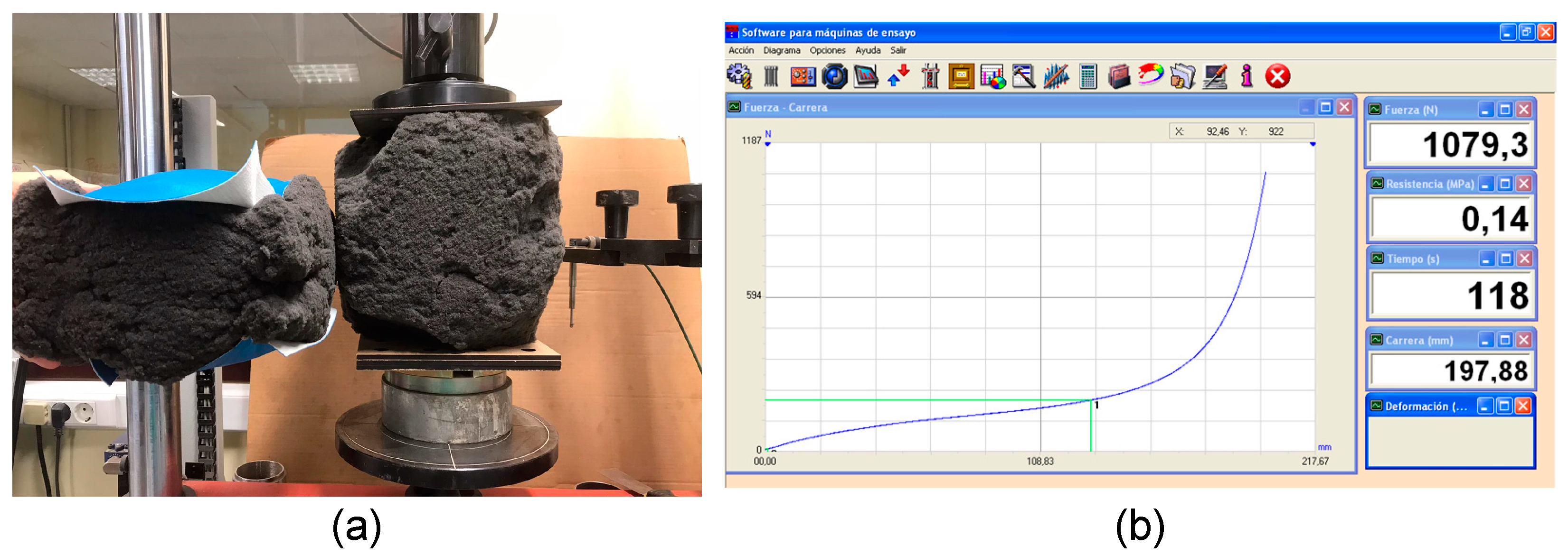
Five different specimens of foam were tested using, as a reference, the Uniaxial compression test: DIN 53577 to know the deformation as a function of the applied stress, observing the process. Figure 3a provides an image that shows a compression test rig with a foam sample placed between two plates. It also shows another specimen significantly pre-compressed, which allows us to evaluate its load-bearing capacity and corresponding deformation. Figure 3b shows the graph generated for one of the tests by the material testing software IBERTEST. Pol. Ind. GITESA, 28814 Danganzo, Madrid, Spain). This graph represents a stress–strain curve in which the applied force (1079.3 N) and the corresponding deformation (197.88 mm) of a foam sample were measured. The compressive strength (0.14 MPa) and other parameters such as test time (118 s) were also recorded. In this graph, the increasing slope of the curve indicates the behavior of the material under compression, allowing analysis of how the foam deforms as the force increases. This type of information is essential for evaluating the impact absorption properties or the load-bearing capacity of the foam, which are key aspects for characterizing the material.
The test proceeded first to measure the thickness dimensions of the foam sample (pre-loaded). It was then compressed to a deformation of 25% at a defined rate. Then, it did the same with a deformation of 40%. Finally, it was compressed to 75% of its original thickness shape, and the force required to perform this compression was measured and recorded.
This test involved applying a compressive force to the specimen and measuring the deformation of the material. Each specimen was tested 8 times using the same compressive test to know the coefficient variation.
Based on the data obtained in the laboratory and in the joint tests carried out, the behavior of the material was modeled, according to the following calculation results:
The stress–strain curves obtained from uniaxial compression tests were conducted on five different foam specimens, each tested 8 times under the same compression conditions. These tests were performed using the DIN 53577 Compression Load Deflection (CLD) methodology, a widely recognized standard in Europe for assessing the compressive behavior of foam materials. Each foam specimen, with dimensions of 200 mm × 200 mm × 200 mm, was subjected to eight repeated compressive tests to evaluate the consistency and reliability of its mechanical properties. The larger specimen size used in these tests, compared to the standard dimensions (100 mm × 100 mm × 50 mm), provides a more comprehensive understanding of the foam’s behavior under significant loading conditions. The resulting stress–strain curves illustrate the characteristic deformation behavior of the foam, capturing the initial elastic response, the plateau associated with cell collapse, and the final densification stage.
The stress–strain curves of the foam demonstrate a consistent progression through distinct regions similar to the theoretical Schematic compressive stress–strain curve for a foam shown by Eaves, 2004 [27]. Initially, all curves exhibit a linear increase in stress with strain, reflecting elastic behavior where the foam deforms proportionally to the applied stress. This initial section, known as the linear region, aligns with Region 1 where cell walls bend without collapsing. Following this step, a noticeable plateau appears in the curves, marking the plateau region. In this middle section, corresponding to Region 2, the foam’s cells begin to collapse, resulting in significant deformation with minimal increase in stress. As strain continues to increase, the curves show a sharp rise in stress during the densification region, indicating that the foam is undergoing densification in Region 3. At this stage, the cell walls are fully compressed, leading to a considerable increase in material stiffness.

3. Results

3.1. Characterization of Compressive Behavior in Foam: Analysis and Curve Fitting

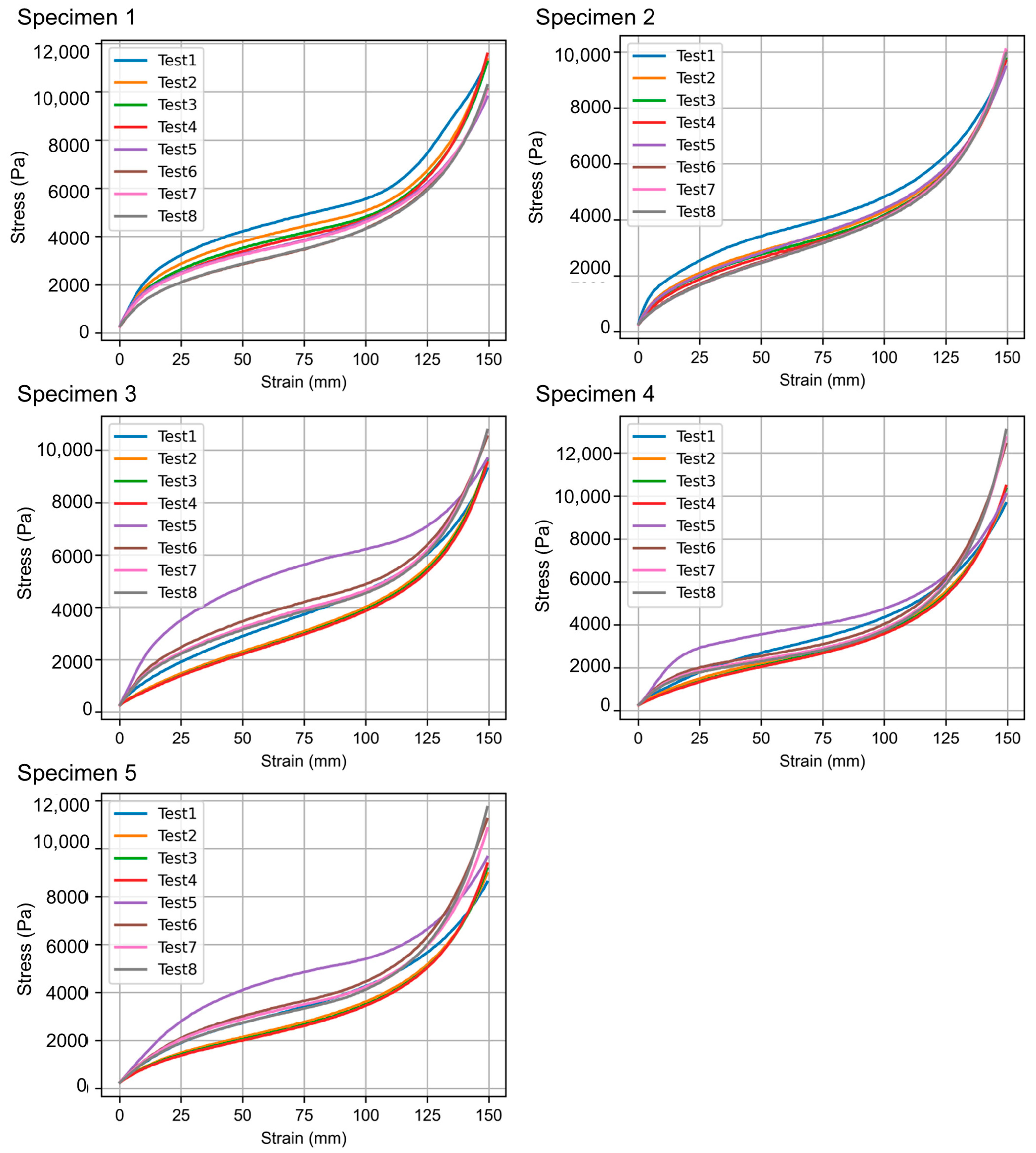
Understanding the compressive behavior of foam materials is crucial for assessing their performance in various applications. This assessment involves analyzing the stress–strain relationships that characterize how the foam responds under load. Figure 4 presents the stress–strain curves of the foam specimens, highlighting three distinct regions: the linear region, the plateau region, and the densification region. Across the five specimens with eight tests, the foam demonstrates good reproducibility, with curves for each specimen closely overlapping. This consistency is crucial for ensuring reliable performance in applications. However, slight deviations are observed in some tests, such as Test 8, particularly within the densification region. These minor variations might be attributed to small differences in foam structure or test conditions. Overall, the foam’s compressive behavior remains consistent across different iterations, reinforcing its reliability.
When comparing specimens, the stress–strain behavior is notably similar across all five samples, indicating uniform material properties. This consistency is essential for practical applications, ensuring reliable performance. Although the point where densification begins varies slightly between specimens, this variation is likely due to differences in foam density or minor manufacturing inconsistencies. The tested specimens, being significantly larger than the standard size specified in DIN 53577 (200 mm × 200 mm × 200 mm), might exhibit different stress distributions. Nonetheless, the overall similarity in behavior suggests that the increased size did not introduce significant variability in the results, as seen in Figure 4.
The graphs offer a thorough understanding of the compressive behavior of the foam specimens. The foam exhibits consistent performance across various specimens and test iterations, with clear linear, plateau, and densification regions evident in the stress–strain curves. This high level of reproducibility underscores the foam’s reliable and predictable mechanical properties under compression. Consequently, the foam appears well suited for applications requiring uniform compressive strength and deformation characteristics. Further analysis could involve calculating precise values for the modulus of elasticity in the linear region, the plateau stress, and the strain at which densification commences, providing more quantitative insights into the material’s properties. Ultimately, the goal is to develop an equation for the characteristic curve based on these extensive tests to better describe the foam’s behavior.
The curves illustrate consistent performance across different specimens and test iterations, despite some observed hysteresis in the initial iteration of each specimen, where higher stress–strain values were recorded. This observation indicates that, while the tests are reproducible, the first iteration may slightly deviate, suggesting a need to account for hysteresis when developing the characteristic curve equation.
To cluster these signals and calculate the most representative signal of the largest group—assuming the initial signals are discarded—K-means and K-medoids are used, and the results are compared without prior knowledge of the number of clusters. The steps in Python are as follows: (i) Data Preparation: the signals are organized in a matrix, with each row representing one signal, (ii) Calculation of Statistics: statistical measures such as mean, variance, etc., can be used, or the entire signals can be directly employed, (iii) Application of Clustering Algorithms: K-means and K-medoids are applied for clustering. To determine the optimal number of clusters, the elbow method or the silhouette criterion can be used, and (iv) Comparison of Results: the outcomes of both methods are evaluated and compared, similar to what is performed in [28,29].
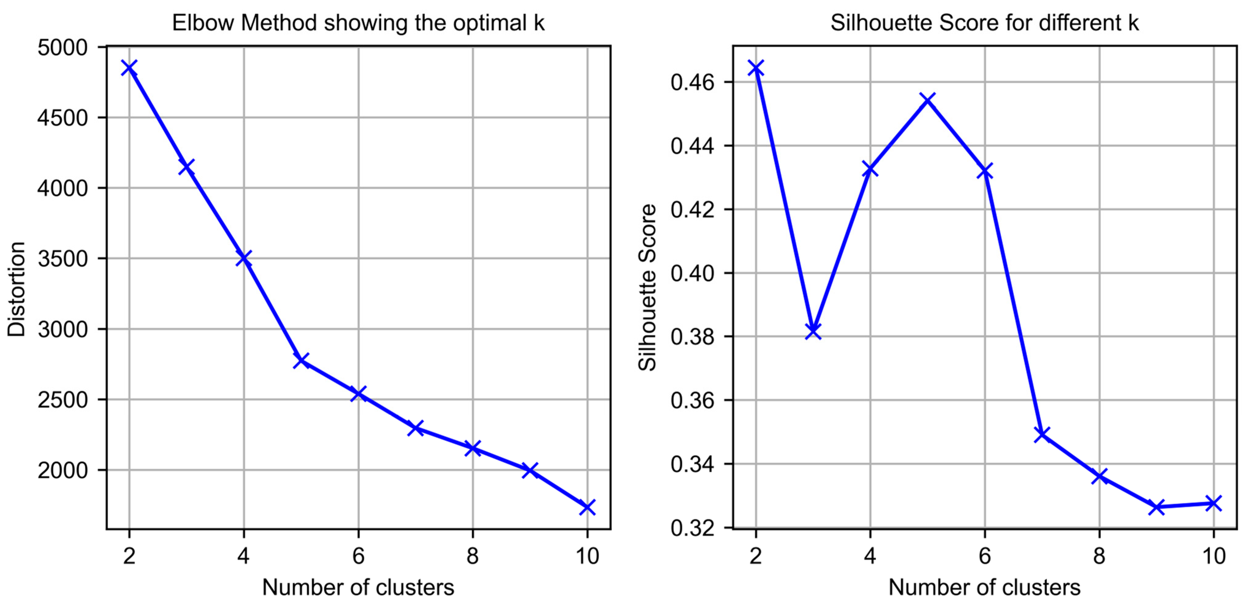
With the focus on clustering the signals based on their compressive stress–strain characteristics, next steps are followed. The first major step is determining the optimal number of clusters. To cluster signals based on their compressive stress–strain characteristics, the initial task is to determine the optimal number of clusters. This task is achieved through the use of two key methods: the “elbow method” and silhouette scores. The elbow method involves evaluating the sum of distortions across a range of cluster numbers (k). Distortion is quantified as the average distance between each data point and the nearest cluster center. By plotting these distortions against the number of clusters, a distinct “elbow” shape often emerges. This elbow represents a point where increasing the number of clusters yields diminishing returns in reducing distortion, suggesting the optimal number of clusters. In parallel, silhouette scores are computed for each value of k. These scores measure the extent to which each data point is similar to points in its own cluster compared to points in other clusters. A higher silhouette score indicates better-defined clusters. By plotting silhouette scores, the peak of the curve helps to identify the value of k that results in the most coherent clustering structure. Together, the elbow method and silhouette scores provide a robust approach to selecting the number of clusters, ensuring that the clustering solution is both effective and interpretable. In Figure 5, these results are shown to visually identify the optimal k, where the elbow in the distortion curve and the peak in the silhouette score indicate the most appropriate cluster count.
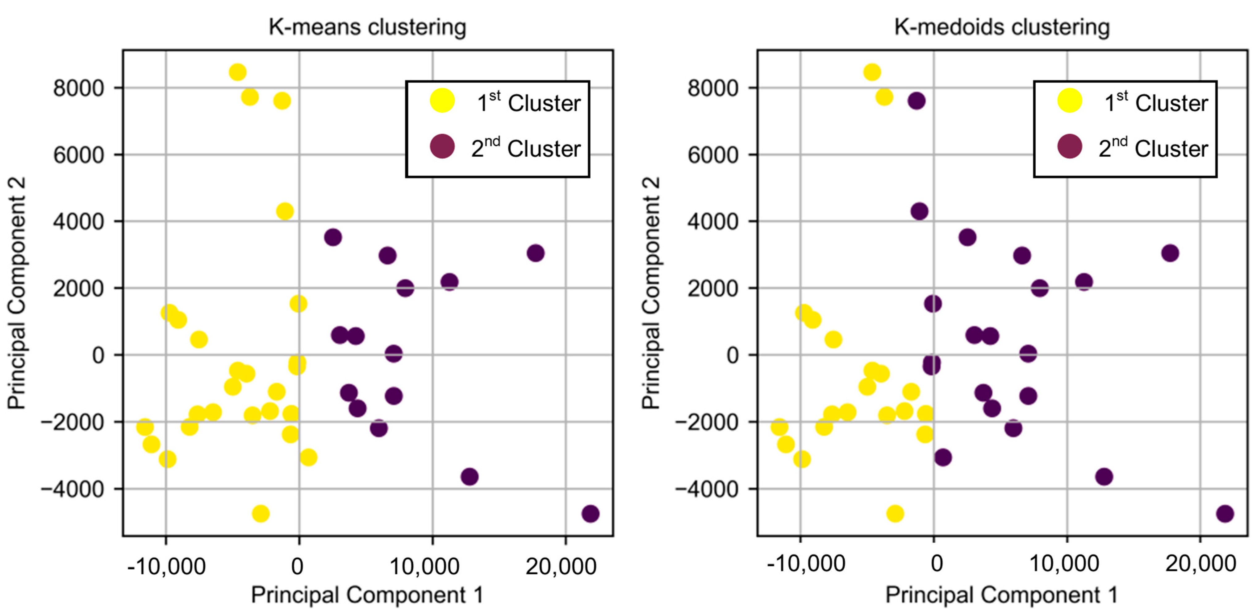
Once the optimal number of clusters is determined, both K-means and K-medoids clustering algorithms are applied. The clusters are visually represented in Figure 6, using a 2D projection of the signals obtained through a Principal Component Analysis (PCA).
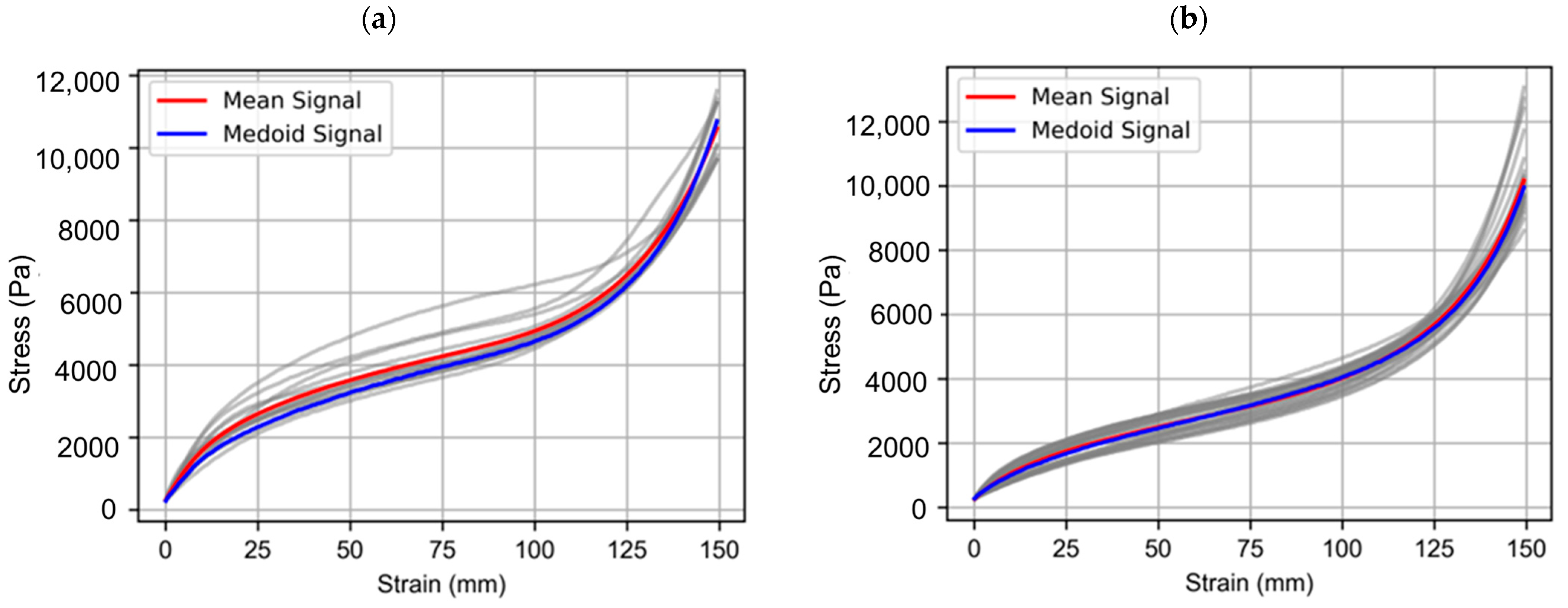
For each cluster, Figure 7 plots all signals in gray, highlighting the mean signal and the medoid (central point) of the clusters in red and blue, respectively. The process helps identify groups of signals with similar behavior, as well as representative signals for each group, which is crucial for understanding the underlying patterns in the data.
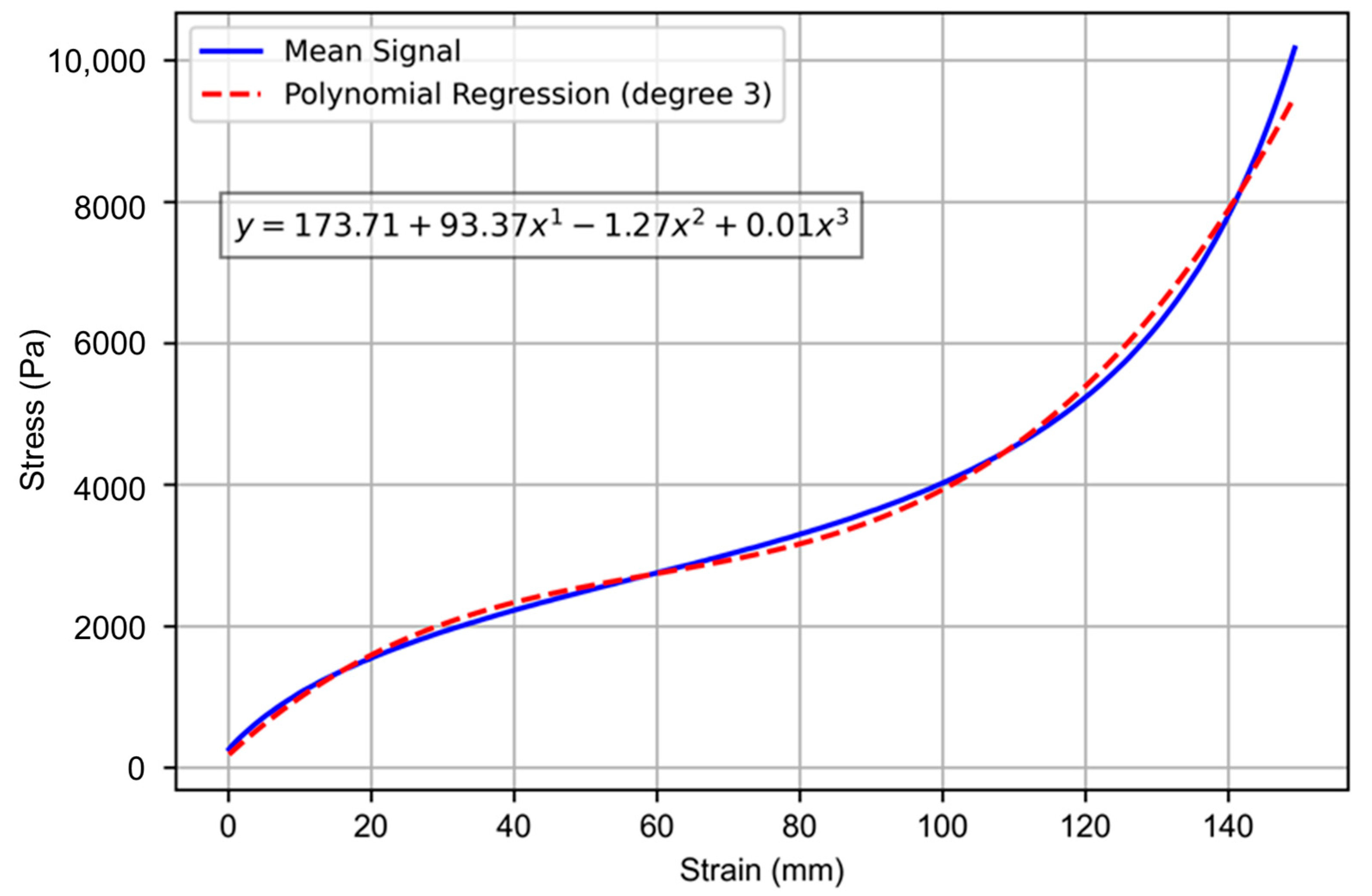
In the final step, a polynomial regression is performed to model the relationship between strain and stress for the mean signal of the second cluster, as it can be seen in Figure 8.

3.2. New Recovered Foam Impact Absorption System Modelization

Liberati et al. [16] concluded that recycled foam can be applied to other uses at the end of their useful life, and the properties of the recycled materials can be adapted to other industrial applications.
As Kauvaka et al. [30] confirmed, polyurea foam samples showed significant recovery within minutes, which is a promising attribute for increased impact efficiency in repeated loading scenarios. A new system was designed, including old foam cubes, with efforts not to apply other mechanical or thermal processes.
Once the materials to be reused in the final design of the system were characterized, a modeling of both the individual elements and the total designed set was carried out in order to perform a finite element analysis, thus ensuring the correct functioning of the system for the protection of users in dynamic leisure facilities.

3.2.1. Cube Modelization

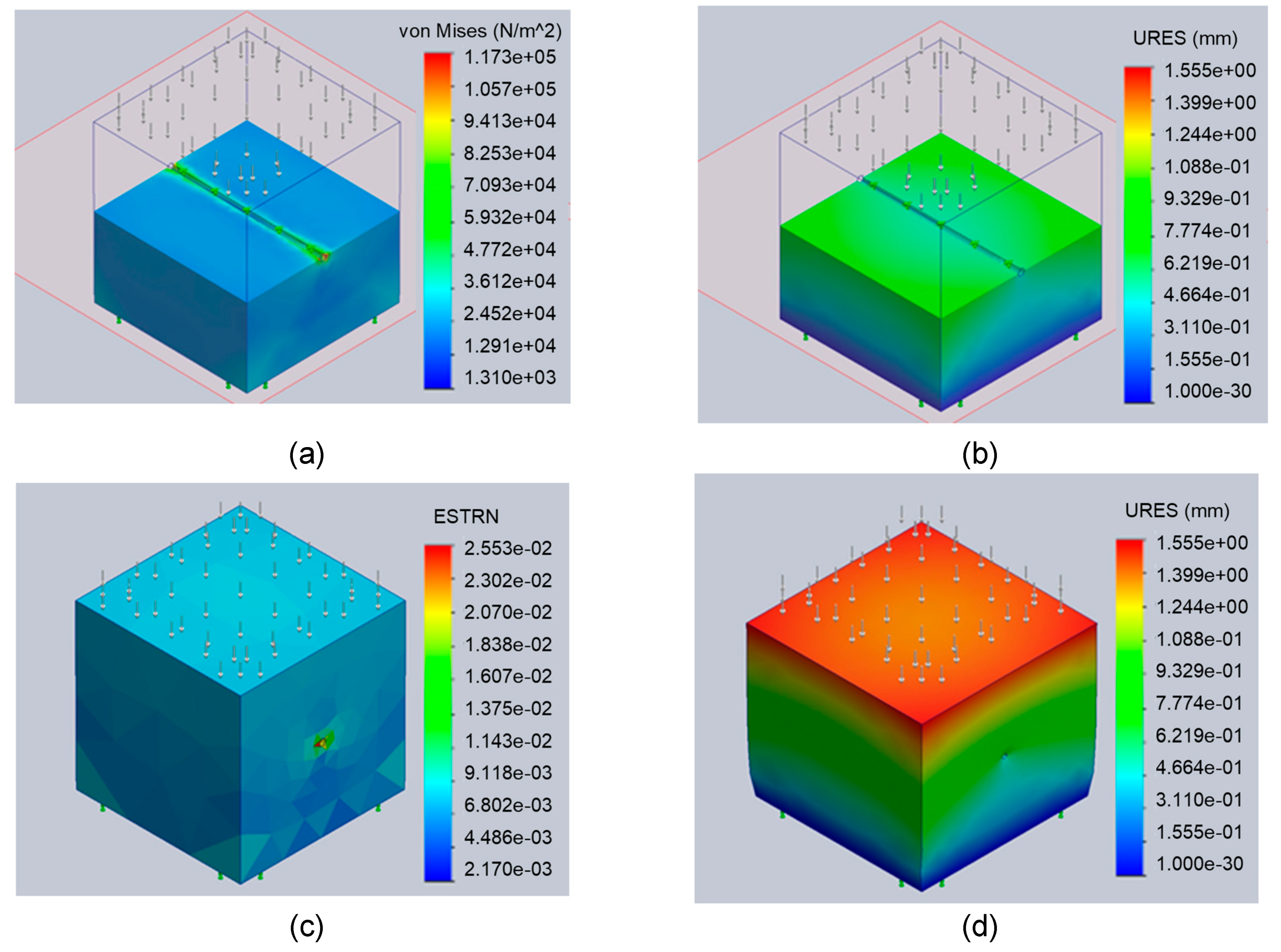
Three different configurations for different compression deformation ratios were simulated: 25%, 50%, and 75% to choose the best configuration that maintains the safety of the users and facilitates its manufacture and assembly. This modelization has included an element that will keep the cubes in the right place when an impact will occur, as it can be seen in Figure 9.
For this modelization, a curvature-based solid mesh with 16 Jacobian points was used for high quality meshing, using high order quadratic elements that ensured high mesh quality. Different sizes and number of nodes were used, although the results obtained did not show significant differences, so the mesh with the lowest computational cost (3840 nodes, 2550 elements, 99.3% of elements with an aspect ratio of less than three and zero distorted elements) was chosen.
The results of the FMEA analysis confirmed that the old foam cubes that were to be discarded can perform the necessary protective function by ensuring a maximum deformation of 50% desired to ensure the health of users in leisure facilities of this type.

3.2.2. New Recovered Foam Impact Absorption System Modelization

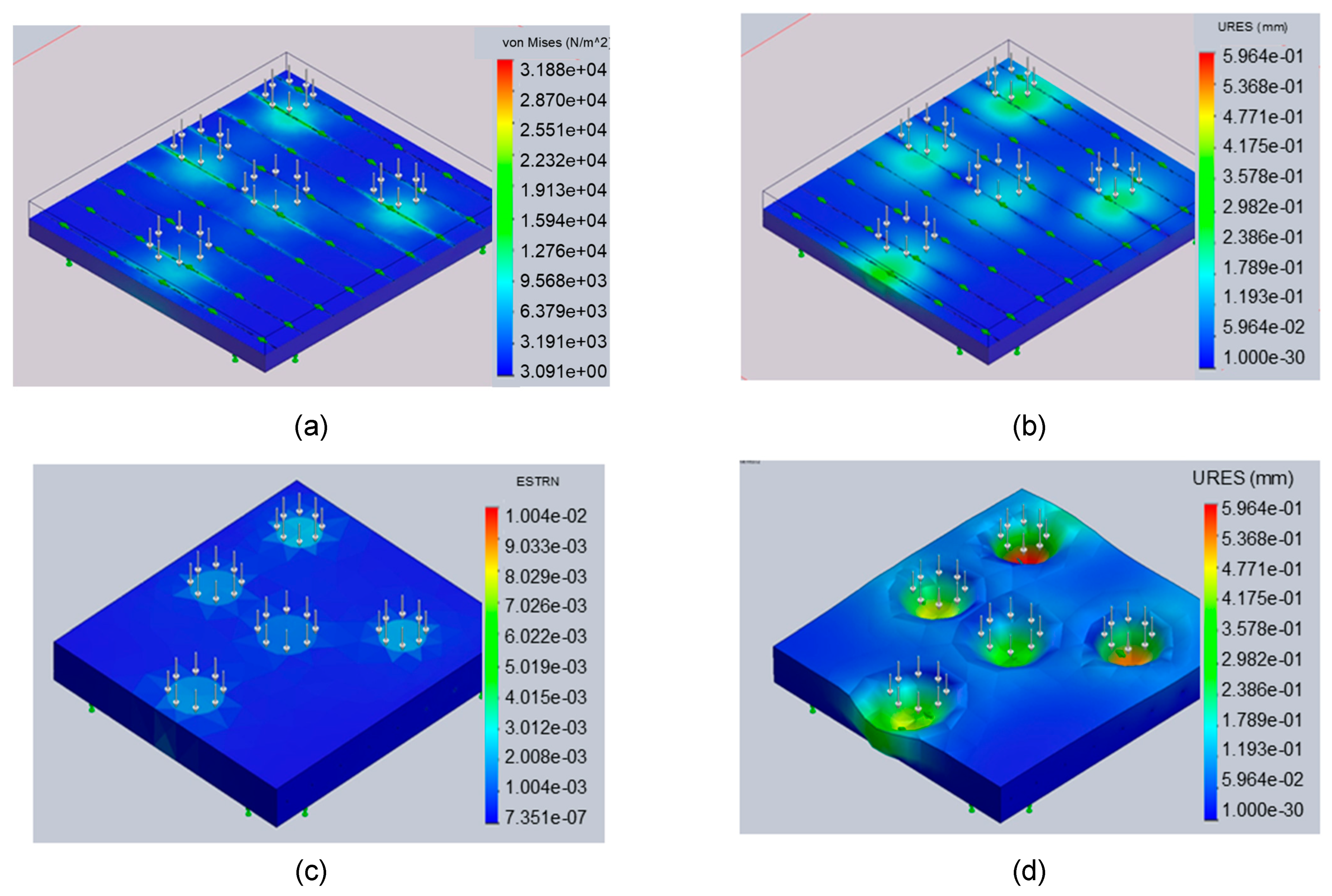
Before proceeding to the fabrication of the prototypes of the newly designed impact absorption system, we proceeded to model the performance of the cube assembly against the impact of five users (100 kg/user) simultaneously.
For this purpose, the same parameters of the solver and the material simulated in the individual cube were used, requiring 178,604 nodes and 124,230 elements.
As seen in Figure 10, the maximum stress reached in the simulation is 3.188 × 10⁴ N/m2, and the maximum strain drops to 0.5 mm.
The results of the simulation of the elements as a whole demonstrated the capacity of the material to ensure the physical safety of the users, since the limits established in the previous analysis of 50% of the deformation and 10% of the deformation were not exceeded.

3.3. New Recovered Foam Impact Absorption System Design and Manufacture

The newly designed system features a set of reused buckets connected by longitudinal ropes, which ensure that the buckets remain in the correct working position in the event of a fall. These ropes are attached to a metal framework that maintains the tension of the ropes while also supporting a canvas. The canvas serves two purposes: it ensures the system remains clean and allows the buckets to deform according to the severity of an impact.
The most important design parameters considered were the following:
  • Maximizing the use of recycled materials: The system prioritizes the reuse of available materials, especially the buckets, to minimize environmental impact.
  • Modularity of the design: The system is designed to be modular, allowing for easy adaptation to different spaces and requirements. This modularity also facilitates installation and maintenance.
  • Ease of maintenance and bucket replacement: The system is designed so that buckets can be easily replaced or maintained without needing to disassemble the entire structure. This design ensures greater durability and long-term functionality.
Figure 11 shows the detail of the technical solution achieved, which is made up of the following elements:
  • Modular metal structure that serves as a resistant frame and allows the use of standard joining elements, allowing the goal of ease of assembly and maintenance and adaptability to various spaces to be achieved.
  • A unifying canvas from textile waste in the manufacture of other protection elements of the same leisure center. This canvas provides uniformity, limits the movements of the unitary foam elements, and allows the hygiene of the system to be maintained.
  • A set of unitary foam elements reused from the previous activity of the leisure facility and that were previously eliminated by sending them to landfill, joined together by central wire ropes that make them work as a single protective element.
  • Some union elements of the protective canvas and foam elements to the structure for easy maintenance and installation.
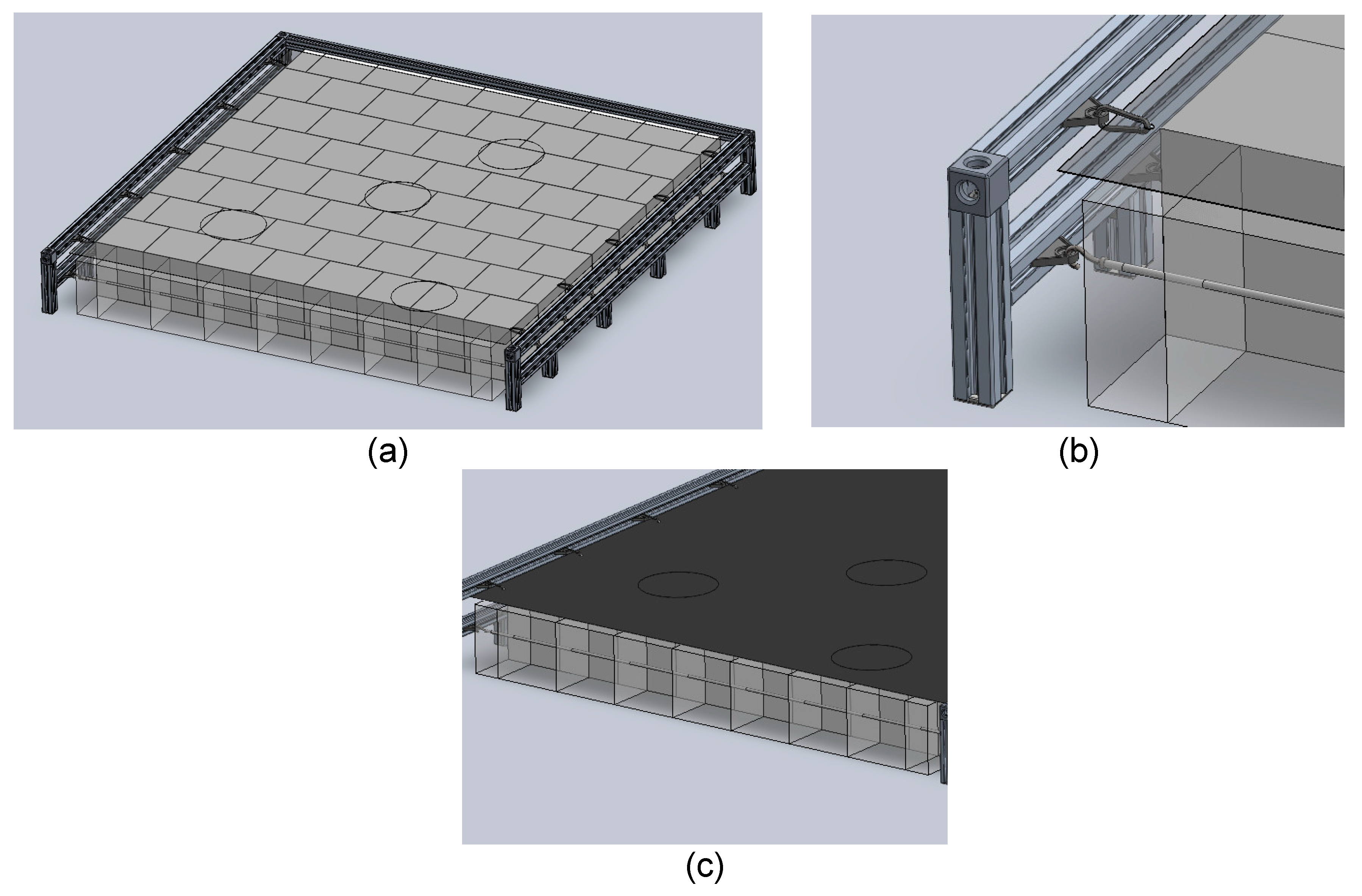
Figure 11. New technical solution elements: (a) global assembly of the technical solution, (b) canvas union detail/unitary foam element with the structure, and (c) union between unitary foam elements.
Applsci 14 09549 g011

4. Conclusions

The presented paper focuses on developing sustainable impact absorption systems by repurposing deteriorated foam materials from leisure facilities. This initiative aims to address the challenges of foam degradation, enhancing both environmental sustainability and safety. This approach represents a significant advancement in creating effective anti-impact measures while contributing to environmental conservation. The following conclusions emerge from the work carried out:
This study provides a detailed analysis of the compressive behavior of foam specimens using stress–strain curves, revealing consistent performance across multiple tests and specimens.
Depending on the orientation of the cube, the pressure that causes a given deformation varies (anisotropy). It is also observed that, with the exception of isolated cases, as the cube is subjected to several tests, it deforms more under the same load.
The characterization tests of the deteriorated material cubes showed that their ability to absorb impacts was not greatly affected, and they can be reused in impact absorption systems.
The finite element modeling of both the individual elements and the newly designed system has allowed us to test the performance against multiple falls of users, ensuring their safety and physical integrity.
With the design of the new technical solution achieved, the environmental impact of the company was drastically reduced since it has been based on the reuse of discarded materials in the other activities of the facility.
Likewise, the safety of users of active leisure centers was greatly increased, allowing the prevention of injuries resulting from falls and blows against rigid elements of the facility.
Although this study demonstrates the potential of reusing deteriorated foam materials in impact absorption systems, further research is recommended to explore the long-term performance of these reused materials under varying environmental conditions. Additionally, identifying other applications where these reused foams could be effectively implemented, such as in automotive, construction, or packaging sectors, would broaden their potential for reuse and contribute to greater environmental sustainability. Collaboration with industrial partners may also help scale this solution, making it more widely applicable across different sectors beyond leisure facilities.
The analysis of the microstructure of the material by means of SEM and XRD is essential to understand the material nature, so in future works to improve the correlation between the material properties and the results obtained, it would be interesting to conduct such analyses.

Author Contributions

Conceptualization, methodology, and formal analysis, S.M.-S.; software, validation, P.B. and F.V.; investigation, M.Á.M.-A. and P.V.R.; writing—original draft preparation, S.M.-S. and F.V.; writing—review and editing, S.M.-S. and F.V.; supervision, project administration, and funding acquisition, S.M.-S. All authors have read and agreed to the published version of the manuscript.

Funding

This research was funded by Gobierno de Navarra, grant number 0011-1365-2022--000131 Sistemas de Absorción de Impacto de Foam Recuperado-Clashfoam.

Institutional Review Board Statement

Not applicable.

Informed Consent Statement

Not applicable.

Data Availability Statement

The data presented in this study are available on request from the corresponding author.

Conflicts of Interest

The authors declare no conflicts of interest.

References

  1. Juanga-Labayen, J.P.; Labayen, I.V.; Yuan, Q. A Review on Textile Recycling Practices and Challenges. Textiles 2022, 2, 174–188. [Google Scholar] [CrossRef]
  2. Zamani, B.; Svanström, M.; Peters, G.; Rydberg, T. A Carbon Footprint of Textile Recycling. A Case Study in Sweden. J. Ind. Ecol. 2008, 19, 676–687. [Google Scholar] [CrossRef]
  3. Hawley, J.M. Textile Recycling as a System: A Micro/Macro Analysis. J. Fam. Consum. Sci. 2000, 92, 40. [Google Scholar]
  4. Navone, L.; Moffitt, K.; Hansen, K.-A.; Blinco, J.; Payne, A.; Speight, R. Closing the Textile Loop: Enzymatic Fibre Separation and Recycling of Wool/Polyester Fabric Blends. J. Waste Manag. 2020, 102, 149–160. [Google Scholar] [CrossRef]
  5. Koszewska, M. Challenges for the Textile and Clothing Industry. Autex Res. J. 2018, 18, 337–347. [Google Scholar] [CrossRef]
  6. Valverde, I.C.; Castilla, L.H.; Nuñez, D.F.; Rodriguez-Senıín, E.; de la Mano Ferreira, R. Development of New Insulation Panels Based on Textile Recycled Fibers. Waste Biomass Valor. 2013, 4, 139–146. [Google Scholar] [CrossRef]
  7. Damayanti, D.; Wulandari, L.A.; Bagaskoro, A.; Rianjanu, A.; Wu, H.-S. Possibility Routes for Textile Recycling Technology. Polymers 2021, 13, 3834. [Google Scholar] [CrossRef]
  8. Pensupa, N.; Leu, S.-Y.; Hu, Y.; Du, C.; Liu, H.; Jing, H.; Wang, H.; Lin, C.S.K. Recent Trends in Sustainable Textile Waste Recycling. Methods: Current Situation and Future Prospects. In Chemistry and Chemical Technologies in Waste Valorization. Topics in Current Chemistry Collections; Springer: Cham, Switzerland, 2017. [Google Scholar] [CrossRef]
  9. Chavan, J. Environmental Sustainability through Textile Recycling. Text. Sci. Eng. 2014, S2. [Google Scholar] [CrossRef]
  10. Khan, W.S.; Asmatulu, E.; Uddin, M.N.; Asmatulu, R. Recycling and Reusing of Engineering Materials: Recycling for Sustainable Developments; Elsevier: Amsterdam, The Netherlands, 2022; ISBN 978-0-12-822462-5. [Google Scholar]
  11. Banik, J.; Chakraborty, D.; Rizwan, M.; Shaik, A.H.; Chandan, M.R. Review on Disposal, Recycling and Management of Waste Polyurethane Foams: A Way Ahead. Waste Manag. Res. 2023, 41, 1063–1080. [Google Scholar] [CrossRef]
  12. Dounis, D.V.; Wilkes, G.L. Structure-Property Relationships of Flexible Polyurethane Foams. Polymer 1997, 38, 2819–2828. [Google Scholar] [CrossRef]
  13. Ates, M.; Karadag, S.; Eker, A.A.; Eker, B. Polyurethane Foam Materials and Their Industrial Applications. Polym. Int. 2022, 71, 1157–1163. [Google Scholar] [CrossRef]
  14. Somarathna, H.M.C.C.; Raman, S.N.; Mohotti, D.; Mutalib, A.A.; Badri, K.H. The Use of Polyurethane for Structural and Infrastructural Engineering Applications: A State-of-the-Art Review. Constr. Build. Mater. 2018, 190, 995–1014. [Google Scholar] [CrossRef]
  15. Kylili, A.; Seduikyte, L.; Fokaides, P.A. 9—Life Cycle Analysis of Polyurethane Foam Wastes. In Recycling of Polyurethane Foams; Thomas, S., Rane, A.V., Kanny, K., V.K., A., Thomas, M.G., Eds.; Plastics Design Library; William Andrew Publishing: Norwich, NY, USA, 2018; pp. 97–113. ISBN 978-0-323-51133-9. [Google Scholar]
  16. Liberati, G.; Biagi, F.; Nanni, A.; Parisi, M.F.; Barbaresi, L.; Querci, L.; Ceccarelli, S.; Regazzi, M.; Bonoli, A.; Colonna, M. Mechanical Recycling of Foam from End-of-Life Mattresses by AIR-LAY Process for the Production of New Mattresses with a Fully Circular Approach. Clean. Mater. 2024, 12, 100249. [Google Scholar] [CrossRef]
  17. Miltz, J.; Ramon, O. Energy Absorption Characteristics of Polymeric Foams Used as Cushioning Materials. Polym. Eng. Sci. 1990, 30, 129–133. [Google Scholar] [CrossRef]
  18. de Souza, F.M.; Kahol, P.K.; Gupta, R.K. Introduction to Polyurethane Chemistry. In Polyurethane Chemistry: Renewable Polyols and Isocyanates; ACS Symposium Series; American Chemical Society: Washington, DC, USA, 2021; Volume 1380, pp. 1–24. ISBN 978-0-8412-9840-8. [Google Scholar]
  19. Das, A.; Mahanwar, P. A Brief Discussion on Advances in Polyurethane Applications. Adv. Ind. Eng. Polym. Res. 2020, 3, 93–101. [Google Scholar] [CrossRef]
  20. Uttaravalli, A.N.; Dinda, S.; Gidla, B.R. Scientific and Engineering Aspects of Potential Applications of Post-Consumer (Waste) Expanded Polystyrene: A Review. Process Saf. Environ. Prot. 2020, 137, 140–148. [Google Scholar] [CrossRef]
  21. Iwuozor, K.O.; Emenike, E.C.; Ighalo, J.O.; Adeniyi, A.G. Expanded Polyethylene Circularity Potentials: A Comprehensive Overview of Production Process, Applications, and Recycling Techniques. Chem. Afr. 2024, 1–12. [Google Scholar] [CrossRef]
  22. Urtekin, G.; Ullah, M.S.; Yildirim, R.; Ozkoc, G.; Kodal, M. A Comprehensive Review of the Recent Developments in Thermoplastics and Rubber Blends-Based Composites and Nanocomposites. Polym. Compos. 2023, 44, 8303–8329. [Google Scholar] [CrossRef]
  23. Rostami-Tapeh-Esmaeil, E.; Vahidifar, A.; Esmizadeh, E.; Rodrigue, D. Chemistry, Processing, Properties, and Applications of Rubber Foams. Polymers 2021, 13, 1565. [Google Scholar] [CrossRef]
  24. Backes, E.H.; Harb, S.V.; Pinto, L.A.; de Moura, N.K.; de Melo Morgado, G.F.; Marini, J.; Passador, F.R.; Pessan, L.A. Thermoplastic Polyurethanes: Synthesis, Fabrication Techniques, Blends, Composites, and Applications. J. Mater. Sci. 2024, 59, 1123–1152. [Google Scholar] [CrossRef]
  25. Chruściel, J.J. Modifications of Textile Materials with Functional Silanes, Liquid Silicone Softeners, and Silicone Rubbers—A Review. Polymers 2022, 14, 4382. [Google Scholar] [CrossRef] [PubMed]
  26. Adetunji, C.O.; Olaniyan, O.T.; Anani, O.A.; Inobeme, A.; Mathew, J.T. Environmental Impact of Polyurethane Chemistry. In Polyurethane Chemistry: Renewable Polyols and Isocyanates; ACS Symposium Series; American Chemical Society: Washington, DC, USA, 2021; Volume 1380, pp. 393–411. ISBN 978-0-8412-9840-8. [Google Scholar]
  27. Eaves, D. Handbook of Polymer Foams; Rapra Technology Limited: Shrewsbury, UK, 2004; ISBN 978-1-84735-054-1. [Google Scholar]
  28. Diez-Olivan, A.; Penalva, M.; Veiga, F.; Deitert, L.; Sanz, R.; Sierra, B. Kernel Density-Based Pattern Classification in Blind Fasteners Installation. In Hybrid Artificial Intelligent Systems; Martínez de Pisón, F.J., Urraca, R., Quintián, H., Corchado, E., Eds.; Springer International Publishing: Cham, Switzerland, 2017; pp. 195–206. [Google Scholar]
  29. Ortego, P.; Diez-Olivan, A.; Del Ser, J.; Veiga, F.; Penalva, M.; Sierra, B. Evolutionary LSTM-FCN Networks for Pattern Classification in Industrial Processes. Swarm Evol. Comput. 2020, 54, 100650. [Google Scholar] [CrossRef]
  30. Kauvaka, P.; Smeets, M.; Koohbor, B.; Youssef, G. Impact Response of Polyurea Elastomeric Foams. J. Dyn. Behav. Mater. 2024, 10, 210–222. [Google Scholar] [CrossRef]
Figure 1. Polyurethane (PU) foam cubes pool in recreational facilities.
Applsci 14 09549 g001
Figure 2. Specimens in the compression set-up at the (a) start of the compression test and (b) the mid-point of travel.
Applsci 14 09549 g002
Figure 3. Compression test and software used for the capture and measurement of the strain–stress curve. (a) set-up for experimental testing and (b) dedicated software for tensile testing.
Applsci 14 09549 g003
Figure 4. Stress–strain curves of foam specimens demonstrating the linear, plateau, and densification regions.
Applsci 14 09549 g004
Figure 5. Optimal number of clusters determined using the elbow method and silhouette scores.
Applsci 14 09549 g005
Figure 6. Visual representation of the clusters formed by K-means and K-medoids, projected onto two dimensions using Principal Component Analysis (PCA).
Applsci 14 09549 g006
Figure 7. Stress–strain curves, in gray lines, of (a) cluster 1 and (b) cluster 2 with its mean and medoid (central point) in red and blue, respectively.
Applsci 14 09549 g007
Figure 8. Polynomial regression modeling the relationship between strain and stress for the mean signal of the second cluster.
Applsci 14 09549 g008
Figure 9. Foam cube modelization: (a) stress (b) strain, (c) ESTRN: equivalent unit strain, and (d) strain.
Applsci 14 09549 g009
Figure 10. New system modelization: (a) stress, (b) strain, (c) ESTRN: equivalent unit strain, and (d) strain (scale 300%).
Applsci 14 09549 g010
Table 1. Materials applied in impact absorption or protective systems.
Material TypeCommon ApplicationsKey Properties for Impact Absorption
Polyurethane (PU) FoamAutomotive interiors, packaging, leisure facilities, sports equipmentLightweight, flexible, excellent energy absorption, customizable densities [19]
Expanded Polystyrene (EPS)Helmets, packaging, construction insulationRigid, good energy dissipation, low density, brittle under repeated impact [20]
Polyethylene (PE) FoamSports mats, automotive, protective packagingLightweight, resilient, durable, excellent cushioning, closed-cell structure [21]
Neoprene RubberWetsuits, sports equipment, industrial paddingElastic, good impact resistance, high durability, moisture resistance [22]
Ethylene Vinyl Acetate (EVA) FoamFootwear, sports equipment, protective paddingSoft, flexible, shock-absorbing, good recovery after compression [23]
Thermoplastic Polyurethane (TPU)Footwear, mobile device protection, automotive componentsHighly elastic, excellent impact resistance, good wear and abrasion resistance [24]
Silicone RubberMedical devices, electronic protection, sports equipmentFlexible, temperature resistant, good shock absorption, durable [25]
Disclaimer/Publisher’s Note: The statements, opinions and data contained in all publications are solely those of the individual author(s) and contributor(s) and not of MDPI and/or the editor(s). MDPI and/or the editor(s) disclaim responsibility for any injury to people or property resulting from any ideas, methods, instructions or products referred to in the content.