

A Short Review on the Wire-Based Directed Energy Deposition of Metals: Mechanical and Microstructural Properties and Quality Enhancement


Abstract
1. Introduction
2. Metals Used in WDED and Types of Microstructure and Mechanical Properties
2.1. Iron-Based Alloys (Steels)
2.2. Titanium-Based Alloys
2.3. Aluminum-Based Alloys
2.4. Copper-Based Alloys
2.5. Mg and Ni Alloys

| Technique | Material | Process Parameters | Microstructure | Condition | YS (MPa) | UTS (MPa) | El (%) | Hardness (GPa) | Reported by |
|---|---|---|---|---|---|---|---|---|---|
| EBDED | Inconel 738 | δ-phase | - | 665 | 984 | 21 | - | [103] | |
| EBDED | Inconel 738 | δ-phase + γ″/γ′ | Direct aging heat treatment: 720 °C × 8 h/furnace cooling to 620 °C × 8 h/air cooling | 973 | 1223 | 7.7 | - | [103] |
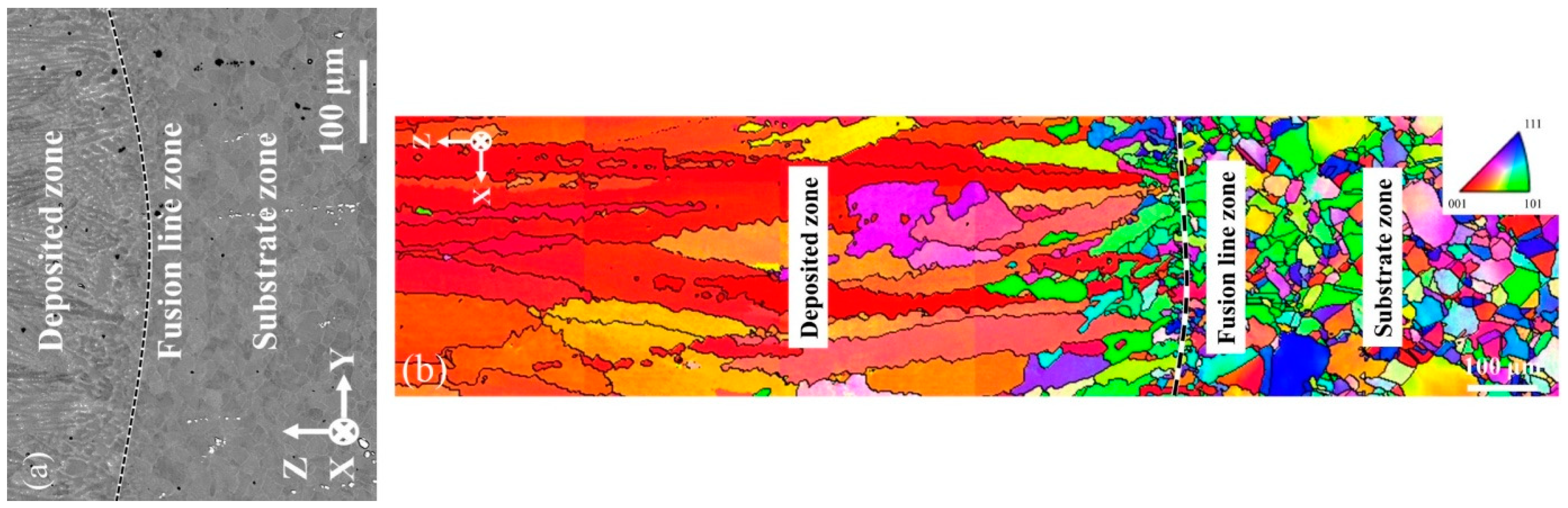
- Deposition (D)
- Diffusion line (FL)
- Substrate (S)
3. Quality Improvement
3.1. Machining
3.2. Heat Treatment
3.3. Surface Finishing
4. Practical Implications
5. Conclusions
Funding
Conflicts of Interest
References
- Gibson, I.; Rosen, D.; Stucker, B. Directed Energy Deposition Processes. In Additive Manufacturing Technologies; Springer: New York, NY, USA, 2015. [Google Scholar]
- Ghasempour-mouziraji, M.; Lagarinhos, J.; Afonso, D. A review study on metal powder materials and processing parameters in Laser Metal Deposition. Opt. Laser Technol. 2023, 170, 110226. [Google Scholar] [CrossRef]
- Collins, S. What’s New with ASTM F42 on Additive Manufacturing Shane Collins; ASTM: West Conshohocken, PA, USA, 2018. [Google Scholar]
- Tee, Y.L.; Tran, P.; Leary, M.; Pille, P.; Brandt, M. 3D Printing of polymer composites with material jetting: Mechanical and fractographic analysis. Addit. Manuf. 2020, 36, 101558. [Google Scholar] [CrossRef]
- Bai, Y.; Wagner, G.; Williams, C.B. Effect of particle size distribution on powder packing and sintering in binder jetting additive manufacturing of metals. J. Manuf. Sci. Eng. Trans. ASME 2017, 139, 081019. [Google Scholar] [CrossRef]
- Park, S.I.; Rosen, D.W.; Choi, S.k.; Duty, C.E. Effective mechanical properties of lattice material fabricated by material extrusion additive manufacturing. Addit. Manuf. 2014, 1, 12–23. [Google Scholar] [CrossRef]
- Pagac, M.; Hajnys, J.; Ma, Q.-P.; Jancar, L.; Jansa, J.; Stefek, P.; Mesicek, J. A Review of Vat Photopolymerization Technology: Materials, Applications, Challenges, and Future Trends of 3D Printing. Polymers 2021, 13, 598. [Google Scholar] [CrossRef]
- Sola, A.; Defanti, S.; Mantovani, S.; Merulla, A.; Denti, L. Technological Feasibility of Lattice Materials by Laser-Based Powder Bed Fusion of A357.0. 3D Print Addit. Manuf. 2020, 7, 1–7. [Google Scholar] [CrossRef]
- Cedeño-Viveros, L.D.; Vázquez-Lepe, E.; Rodríguez, C.A.; García-López, E. Influence of process parameters for sheet lamination based on laser micro-spot welding of austenitic stainless steel sheets for bone tissue applications. Int. J. Adv. Manuf. Technol. 2021, 115, 247–262. [Google Scholar] [CrossRef]
- Ghasempour-Mouziraji, M.; Afonso, D.; Hosseinzadeh, S.; Goulas, C.; Najafizadeh, M.; Hosseinzadeh, M.; Ganji, D.; de Sousa, R.A. Modeling the effect of processing parameters on temperature history in Directed Energy Deposition: An analytical and finite element approach. Rapid Prototyp. J. 2023, 30, 338–349. [Google Scholar] [CrossRef]
- Pinkerton, A.J. An analytical model of beam attenuation and powder heating during coaxial laser direct metal deposition. J. Phys. D Appl. Phys. 2007, 40, 7323–7334. [Google Scholar] [CrossRef]
- Boisselier, D.; Sankaré, S.; Engel, T. Improvement of the laser direct metal deposition process in 5-axis configuration. Phys. Procedia 2014, 56, 239–249. [Google Scholar] [CrossRef]
- Kovalchuk, D.; Melnyk, V.; Melnyk, I. A Coaxial Wire-Feed Additive Manufacturing of Metal Components Using a Profile Electron Beam in Space Application. J. Mater. Eng. Perform. 2022, 31, 6069–6082. [Google Scholar] [CrossRef]
- Belotti, L.P.; van Dommelen, J.A.W.; Geers, M.G.D.; Goulas, C.; Ya, W.; Hoefnagels, J.P.M. Microstructural characterisation of thick-walled wire arc additively manufactured stainless steel. J. Mater. Process. Technol. 2022, 299, 117373. [Google Scholar] [CrossRef]
- Bor, T.C.; Strik, D.H.; Rezaeinejad, S.S.; Helthuis, N.G.J.; Vos, G.S.; Luckabauer, M.; Akkerman, R. A Feasibility Study on Friction Screw Extrusion Additive Manufacturing of AA6060. In Minerals, Metals and Materials Series; Springer: Cham, Switzerland, 2023; pp. 27–38. [Google Scholar] [CrossRef]
- Greer, C.; Nycz, A.; Noakes, M.; Richardson, B.; Post, B.; Kurfess, T.; Love, L. Introduction to the design rules for Metal Big Area Additive Manufacturing. Addit. Manuf. 2019, 27, 159–166. [Google Scholar] [CrossRef]
- Brubaker, N.; Ali, H.; Dhakal, S.; van Rooyen, N.; Jaster, M.L.; Charit, I.; Jaques, B.; Maughan, M.R. Investigating Microstructure and Properties of 316L Stainless Steel Produced by Wire-Fed Laser Metal Deposition. J. Mater. Eng. Perform. 2022, 31, 3508–3519. [Google Scholar] [CrossRef]
- Ng, G.K.L.; Jarfors, A.E.W.; Bi, G.; Zheng, H.Y. Porosity formation and gas bubble retention in laser metal deposition. Appl. Phys. A 2009, 97, 641–649. [Google Scholar] [CrossRef]
- BLi, B.; Wang, B.; Zhu, G.; Zhang, L.; Lu, B. Low-Roughness-Surface Additive Manufacturing of Metal-Wire Feeding with Small Power. Materials 2021, 14, 4265. [Google Scholar] [CrossRef]
- Wilson, J.M.; Piya, C.; Shin, Y.C.; Zhao, F.; Ramani, K. Remanufacturing of turbine blades by laser direct deposition with its energy and environmental impact analysis. J. Clean. Prod. 2014, 80, 170–178. [Google Scholar] [CrossRef]
- Era, I.Z.; Liu, Z. Effect of process parameters on tensile properties of SS 316 prepared by directional energy deposition. Procedia CIRP 2021, 103, 115–121. [Google Scholar] [CrossRef]
- Nowotny, S.; Scharek, S.; Beyer, E.; Richter, K.H. Laser beam build-up welding: Precision in repair, surface cladding, and direct 3D metal deposition. J. Therm. Spray Technol. 2007, 16, 344–348. [Google Scholar] [CrossRef]
- Xu, X.; Mi, G.; Luo, Y.; Jiang, P.; Shao, X.; Wang, C. Morphologies, microstructures, and mechanical properties of samples produced using laser metal deposition with 316 L stainless steel wire. Opt. Lasers Eng. 2017, 94, 1–11. [Google Scholar] [CrossRef]
- Svetlizky, D.; Das, M.; Zheng, B.; Vyatskikh, A.L.; Bose, S.; Bandyopadhyay, A.; Schoenung, J.M.; Lavernia, E.J.; Eliaz, N. Directed energy deposition (DED) additive manufacturing: Physical characteristics, defects, challenges and applications. Mater. Today 2021, 49, 271–295. [Google Scholar] [CrossRef]
- Shi, Y.; Gong, S.; Xu, H.; Yang, G.; Qiao, J.; Wang, Z.; Zhang, J.; Qi, B. Electron beam metal additive manufacturing: Defects formation and in-process control. J. Manuf. Process. 2023, 101, 386–431. [Google Scholar] [CrossRef]
- Nguyen, H.D.; Pramanik, A.; Basak, A.K.; Dong, Y.; Prakash, C.; Debnath, S.; Shankar, S.; Jawahir, I.S.; Dixit, S.; Buddhi, D. A critical review on additive manufacturing of Ti-6Al-4V alloy: Microstructure and mechanical properties. J. Mater. Res. Technol. 2022, 18, 4641–4661. [Google Scholar] [CrossRef]
- Zykova, A.; Nikonov, S.; Utyaganova, V.; Shamarin, N.; Ivanov, A.; Chumaevskii, A. Process control features of electron-beam additive manufacturing of austenitic stainless steel. Procedia Struct. Integr. 2020, 30, 216–223. [Google Scholar] [CrossRef]
- Fox, J.; Beuth, J. Process mapping of transient melt pool response in wire feed e-beam additive manufacturing of Ti-6Al-4V. In Proceedings of the 24th International SFF Symposium—An Additive Manufacturing Conference, SFF 2013, Austin, TX, USA, 12–14 August 2013; pp. 675–683. [Google Scholar]
- Wu, Q.; Lu, J.; Liu, C.; Shi, X.; Ma, Q.; Tang, S.; Fan, H.; Ma, S. Obtaining uniform deposition with variable wire feeding direction during wire-feed additive manufacturing. Mater. Manuf. Process. 2017, 32, 1881–1886. [Google Scholar] [CrossRef]
- Callanan, J.G.; Black, A.N.; Lawrence, S.K.; Jones, D.R.; Martinez, D.T.; Martinez, R.M.; Fensin, S.J. Dynamic properties of 316l stainless steel repaired using electron beam additive manufacturing. Acta Mater. 2023, 246, 118636. [Google Scholar] [CrossRef]
- Sikan, F. Electron Beam Wire-fed Deposition of Titanium Alloys for Repair Applications. Ph.D. Dissertation, McGill University, Montréal, QC, Canada, October 2022. [Google Scholar]
- Ou, W.; Mukherjee, T.; Knapp, G.L.; Wei, Y.; DebRoy, T. Fusion zone geometries, cooling rates and solidification parameters during wire arc additive manufacturing. Int. J. Heat Mass Transf. 2018, 127, 1084–1094. [Google Scholar] [CrossRef]
- Klobčar, D.; Lindič, M.; Bušić, M. Wire arc additive manufacturing of mild steel. Mater. Geoenviron. 2018, 65, 179–186. [Google Scholar] [CrossRef]
- Rosli, N.A.; Alkahari, M.R.; Abdollah, M.F.b.; Maidin, S.; Ramli, F.R.; Herawan, S.G. Effects of Wire Feeding Angle in Wire Arc Additive Manufacturing. J. Mech. Eng. Res. Dev. 2021, 44, 76100. [Google Scholar]
- Magistrale, L.; Ugues, P.D.; Hermans, I.M.J.M.; Antonio, B. Investigation on Microstructure, Mechanical Properties and Corrosion Resistance of AISI P20 Steel Produced with Wire Arc Additive Manufacturing. Ph.D. Dissertation, Politecnico di Torino, Torino, Italy, 2018. [Google Scholar]
- Aldalur, E.; Veiga, F.; Suárez, A.; Bilbao, J.; Lamikiz, A. Analysis of the Wall Geometry with Different Strategies for High Deposition Wire Arc Additive Manufacturing of Mild Steel. Metals 2020, 10, 892. [Google Scholar] [CrossRef]
- Gowthaman, P.S.; Jeyakumar, S.; Sarathchandra, D. Effect of Heat Input on Microstructure and Mechanical Properties of 316L Stainless Steel Fabricated by Wire Arc Additive Manufacturing. J. Mater. Eng. Perform. 2023, 33, 5536–5546. [Google Scholar] [CrossRef]
- Pant, H.; Arora, A.; Gopakumar, G.S.; Chadha, U.; Saeidi, A.; Patterson, A.E. Applications of wire arc additive manufacturing (WAAM) for aerospace component manufacturing. Int. J. Adv. Manuf. Technol. 2023, 127, 4995–5011. [Google Scholar] [CrossRef]
- Derekar, K.S. Aspects of Wire Arc Additive Manufacturing (WAAM) of Alumnium Alloy 5183. Ph.D. Dissertation, Coventry University, Coventry UK, 2020; pp. 1–227. [Google Scholar]
- Dinovitzer, M.; Chen, X.; Laliberte, J.; Huang, X.; Frei, H. Effect of wire and arc additive manufacturing (WAAM) process parameters on bead geometry and microstructure. Addit. Manuf. 2019, 26, 138–146. [Google Scholar] [CrossRef]
- Hu, Z.; Hua, L.; Qin, X.; Ni, M.; Liu, Z.; Liang, C. Region-based path planning method with all horizontal welding position for robotic curved layer wire and arc additive manufacturing. Robot. Comput. Integr. Manuf. 2022, 74, 102286. [Google Scholar] [CrossRef]
- Kim, K.W.; Kale, A.B.; Cho, Y.H.; Park, S.H.; Lee, K.A. Microstructural and wear properties of WC-12Co cemented carbide fabricated by direct energy deposition. Wear 2023, 518–519, 204653. [Google Scholar] [CrossRef]
- Xie, R.; Liang, T.; Chen, S.; Liu, H. In-depth understanding of rotating toolhead-induced heat generation and material flow behavior in friction-rolling additive manufacturing. Addit. Manuf. 2023, 67, 103496. [Google Scholar] [CrossRef]
- Yu, R.; Yu, S.; Yu, Z.; Zheng, B.; Yu, G. Effect of inter-layer rotary friction processing on porosity of arc-directed energy-deposited high-strength aluminum alloys. J. Mater. Process. Technol. 2023, 316, 117951. [Google Scholar] [CrossRef]
- Tang, W.; Yang, X.; Tian, C. Influence of rotation speed on interfacial bonding mechanism and mechanical performance of aluminum 6061 fabricated by multilayer friction-based additive manufacturing. Int. J. Adv. Manuf. Technol. 2023, 126, 4119–4133. [Google Scholar] [CrossRef]
- Kim, H.J.; Shin, G.Y.; Lee, K.Y.; Shim, D.S. Wear behavior of aluminum-matrix particle (TiH2 and ZrH2)-reinforced composite foam additively manufactured using directed energy deposition. J. Mater. Res. Technol. 2023, 25, 222–230. [Google Scholar] [CrossRef]
- Sun, G.F.; Shen, X.; Wang, Z.; Zhan, M.; Yao, S.; Zhou, R.; Ni, Z. Laser metal deposition as repair technology for 316L stainless steel: Influence of feeding powder compositions on microstructure and mechanical properties. Opt. Laser Technol. 2019, 109, 71–83. [Google Scholar] [CrossRef]
- Guo, D.; Yan, K.; Callaghan, M.D.; Daisenberger, D.; Chatterton, M.; Chen, J.; Wisbey, A.; Mirihanage, W. Solidification microstructure and residual stress correlations in direct energy deposited type 316L stainless steel. Mater. Des. 2021, 207, 109782. [Google Scholar] [CrossRef]
- Tuominen, J.; Kaubisch, M.; Thieme, S.; Näkki, J.; Nowotny, S.; Vuoristo, P. Laser strip cladding for large area metal deposition. Addit. Manuf. 2019, 27, 208–216. [Google Scholar] [CrossRef]
- Reitz, W. A Review of: “Welding Metallurgy and Weldability of Stainless Steel”; John Wiley and Sons, Inc.: Hoboken, NJ, USA, 2006. [Google Scholar] [CrossRef]
- Biyikli, M.; Karagoz, T.; Calli, M.; Muslim, T.; Ozalp, A.A.; Bayram, A. Single Track Geometry Prediction of Laser Metal Deposited 316L-Si Via Multi-Physics Modelling and Regression Analysis with Experimental Validation. Met. Mater. Int. 2022, 29, 807–820. [Google Scholar] [CrossRef]
- Moskvina, V.A.; Melnikov, E.; Panchenko, M.; Maier, G.; Reunova, K.; Astafurov, S.; Kolubaev, E.; Astafurova, E. Stabilization of austenitic structure in transition zone of ‘austenitic stainless steel/NiCr alloy’ joint fabricated by wire-feed electron beam melting. Mater. Lett. 2020, 277, 128321. [Google Scholar] [CrossRef]
- Astafurov, S.; Astafurova, E.; Reunova, K.; Melnikov, E.; Panchenko, M.; Moskvina, V.; Maier, G.; Rubtsov, V.; Kolubaev, E. Electron-beam additive manufacturing of high-nitrogen steel: Microstructure and tensile properties. Mater. Sci. Eng. A 2021, 826, 141951. [Google Scholar] [CrossRef]
- Vorontsov, A.; Astafurov, S.; Melnikov, E.; Moskvina, V.; Kolubaev, E.; Astafurova, E. The microstructure, phase composition and tensile properties of austenitic stainless steel in a wire-feed electron beam melting combined with ultrasonic vibration. Mater. Sci. Eng. A 2021, 820, 141519. [Google Scholar] [CrossRef]
- Melnikov, E.V.; Astafurova, E.; Astafurov, S.; Maier, G.; Moskvina, V.; Panchenko, M.; Fortuna, S.; Rubtsov, V.; Kolubaev, E. Anisotropy of the tensile properties in austenitic stainless steel obtained by wire-feed electron beam additive growth. Lett. Mater. 2019, 9, 460–464. [Google Scholar] [CrossRef]
- Fortuna, S.V.; Filippov, A.V.; Kolubaev, E.A.; Fortuna, A.S.; Gurianov, D.A. Wire feed electron beam additive manufacturing of metallic components. AIP Conf. Proc. 2018, 2051, 020092. [Google Scholar] [CrossRef]
- Feldhausen, T.; Raghavan, N.; Saleeby, K.; Love, L.; Kurfess, T. Mechanical properties and microstructure of 316L stainless steel produced by hybrid manufacturing. J. Mater. Process. Technol. 2021, 290, 116970. [Google Scholar] [CrossRef]
- Astafurova, E.; Reunova, K.; Melnikov, E.; Panchenko, M.; Astafurov, S.; Luchin, A.; Zagibalova, E.; Kolubaev, E. A Comparison of Low-Temperature Deformation Behavior and Fracture in Low-Carbon Steel Specimens Obtained by Electron Beam Additive Manufacturing and Conventional Casting and Normalization. Materials 2023, 16, 446. [Google Scholar] [CrossRef]
- OsipovichOsipovich, K.; Vorontsov, A.; Chumaevskii, A.; Gurianov, D.; Shamarin, N.; Savchenko, N.; Kolubaev, E. Characterization of a Bimetallic Multilayered Composite “Stainless Steel/Copper” Fabricated with Wire-Feed Electron Beam Additive Manufacturing. Metals 2021, 11, 1151. [Google Scholar] [CrossRef]
- Moskvina, V.; Astafurova, E.; Astafurov, S.; Reunova, K.; Panchenko, M.; Melnikov, E.; Kolubaev, E. Effect of Ion-Plasma Nitriding on Phase Composition and Tensile Properties of AISI 321-Type Stainless Steel Produced by Wire-Feed Electron-Beam Additive Manufacturing. Metals 2022, 12, 176. [Google Scholar] [CrossRef]
- Tarasov, S.Y.; Filippov, A.V.; Savchenko, N.L.; Fortuna, S.V.; Rubtsov, V.E.; Kolubaev, E.A.; Psakhie, S.G. Effect of heat input on phase content, crystalline lattice parameter, and residual strain in wire-feed electron beam additive manufactured 304 stainless steel. Int. J. Adv. Manuf. Technol. 2018, 99, 2353–2363. [Google Scholar] [CrossRef]
- Astafurova, E.G.; Panchenko, M.Y.; Moskvina, V.A.; Maier, G.G.; Astafurov, S.V.; Melnikov, E.V.; Fortuna, A.S.; Reunova, K.A.; Rubtsov, V.E.; Kolubaev, E.A. Microstructure and grain growth inhomogeneity in austenitic steel produced by wire-feed electron beam melting: The effect of post-building solid-solution treatment. J. Mater. Sci. 2020, 55, 9211–9224. [Google Scholar] [CrossRef]
- Osipovich, K.S.; Astafurova, E.G.; Chumaevskii, A.V.; Kalashnikov, K.N.; Astafurov, S.V.; Maier, G.G.; Melnikov, E.V.; Moskvina, V.A.; Panchenko, M.Y.; Tarasov, S.Y.; et al. Gradient transition zone structure in ‘steel–copper’ sample produced by double wire-feed electron beam additive manufacturing. J. Mater. Sci. 2020, 55, 9258–9272. [Google Scholar] [CrossRef]
- Moskvina, V.A.; Melnikov, E.; Astafurov, S.; Panchenko, M.; Reunova, K.; Kolubaev, E.; Astafurova, E. Stable high-nickel austenitic steel produced by electron beam additive manufacturing using dual wire-feed system. Mater. Lett. 2021, 305, 130863. [Google Scholar] [CrossRef]
- Wakai, A.; Das, A.; Bustillos, J.; Moridi, A. Effect of solidification pathway during additive manufacturing on grain boundary fractality. Addit. Manuf. Lett. 2023, 6, 100149. [Google Scholar] [CrossRef]
- Mahamood, R.M.; Akinlabi, E.T. Effect of Laser Power and Powder Flow Rate on the Wear Resistance Behaviour of Laser Metal Deposited TiC/Ti6Al4V Composites. Mater. Today Proc. 2015, 2, 2679–2686. [Google Scholar] [CrossRef]
- Huang, S.; Sing, S.L.; de Looze, G.; Wilson, R.; Yeong, W.Y. Laser powder bed fusion of titanium-tantalum alloys: Compositions and designs for biomedical applications. J. Mech. Behav. Biomed. Mater. 2020, 108, 103775. [Google Scholar] [CrossRef]
- Najafizadeh, M.; Bozorg, M.; Bahadoran, A.; Liang, J.; Zhang, D. Compressive and biocorrosion properties of Ti-XAl-2Fe-3Cu alloys fabricated by powder metallurgy. J. Alloys Compd. 2021, 884, 161079. [Google Scholar] [CrossRef]
- Najafizadeh, M.; Bahadoran, A.; Bozorg, M.; Sadeghi, B.; Liang, J.; Zhang, D. Microstructures and mechanical properties of high strength Ti-XAl-2Fe-3Cu alloys fabricated by powder compact extrusion. J. Alloys Compd. 2021, 884, 161136. [Google Scholar] [CrossRef]
- Zhang, G.; Xiong, H.; Yu, H.; Qin, R.; Liu, W.; Yuan, H. Microstructure evolution and mechanical properties of wire-feed electron beam additive manufactured Ti-5Al-2Sn-2Zr-4Mo-4Cr alloy with different subtransus heat treatments. Mater. Des. 2020, 195, 109063. [Google Scholar] [CrossRef]
- Li, Z.; Chang, B.; Cui, Y.; Zhang, H.; Liang, Z.; Liu, C.; Wang, L.; Du, D.; Chang, S. Effect of twin-wire feeding methods on the in-situ synthesis of electron beam fabricated Ti-Al-Nb intermetallics. Mater. Des. 2022, 215, 110509. [Google Scholar] [CrossRef]
- Wang, M.; Hu, J.; Zhu, J.; Zhang, K.; Kovalchuk, D.; Yang, Y.; Wang, H.; Zhang, L.-C.; Huang, A. Microstructure and mechanical properties of Ti-6Al-4V cruciform structure fabricated by coaxial electron beam wire-feed additive manufacturing. J. Alloys Compd. 2023, 960, 170943. [Google Scholar] [CrossRef]
- Shaikh, M.O.; Chen, C.-C.; Chiang, H.-C.; Chen, J.-R.; Chou, Y.-C.; Kuo, T.-Y.; Ameyama, K.; Chuang, C.-H. Additive manufacturing using fine wire-based laser metal deposition. Rapid Prototyp. J. 2020, 26, 473–483. [Google Scholar] [CrossRef]
- Li, Z.; Chang, B.; Zhang, D.; Zhang, H.; Liang, Z.; Wang, L.; Liu, C.; Du, D. Effect of post-heat treatment on Ti2AlNb-based alloy fabricated by twin-wire alternating dual-electron beam additive manufacturing technology. J. Mater. Sci. Technol. 2023, 157, 130–143. [Google Scholar] [CrossRef]
- Kalashnikov, K.N.; Chumaevskii, A.V.; Kalashnikova, T.A.; Kolubaev, E.A. A substrate material and thickness influence on the 3D-printing of Ti–6Al–4V components via wire-feed electron beam additive manufacturing. J. Mater. Res. Technol. 2022, 16, 840–852. [Google Scholar] [CrossRef]
- Pixner, F.; Buzolin, R.; Schönfelder, S.; Theuermann, D.; Warchomicka, F.; Enzinger, N. Contactless temperature measurement in wire-based electron beam additive manufacturing Ti-6Al-4V. Weld. World 2021, 65, 1307–1322. [Google Scholar] [CrossRef]
- Klimenov, V.; Kolubaev, E.; Anatoly, K.; Chumaevskii, A.; Ustinov, A.; Strelkova, I.; Rubtsov, V.; Gurianov, D.; Han, Z.; Nikonov, S.; et al. Influence of the Coarse Grain Structure of a Titanium Alloy Ti-4Al-3V Formed by Wire-Feed Electron Beam Additive Manufacturing on Strain Inhomogeneities and Fracture. Materials 2023, 16, 3901. [Google Scholar] [CrossRef]
- Pixner, F.; Warchomicka, F.; Peter, P.; Steuwer, A.; Colliander, M.H.; Pederson, R.; Enzinger, N. Wire-based additive manufacturing of Ti-6Al-4V using electron beam technique. Materials 2020, 13, 3310. [Google Scholar] [CrossRef]
- Kalashnikov, K.N.; Rubtsov, V.E.; Savchenko, N.L.; Kalashnikova, T.A.; Osipovich, K.S.; Eliseev, A.A.; Chumaevskii, A.V. The effect of wire feed geometry on electron beam freeform 3D printing of complex-shaped samples from Ti-6Al-4V alloy. Int. J. Adv. Manuf. Technol. 2019, 105, 3147–3156. [Google Scholar] [CrossRef]
- Hu, J.; Zhang, J.; Wei, Y.; Chen, H.; Yang, Y.; Wu, S.; Kovalchuk, D.; Liang, E.; Zhang, X.; Wang, H.; et al. Effect of Heat Treatment on Microstructure and Tensile Properties of Ti-6Al-4V Alloy Produced by Coaxial Electron Beam Wire Feeding Additive Manufacturing. JOM 2021, 73, 2241–2249. [Google Scholar] [CrossRef]
- Miller, W.S.; Zhuang, L.; Bottema, J.; Wittebrood, A.J.; De Smet, P.; Haszler, A.; Vieregge, A. Recent development in aluminium alloys for the automotive industry. Mater. Sci. Eng. A 2000, 280, 37–49. [Google Scholar] [CrossRef]
- Hagenlocher, C.; O’Toole, P.; Xu, W.; Brandt, M.; Easton, M.; Molotnikov, A. In process monitoring of the thermal profile during solidification in laser directed energy deposition of aluminium. Addit. Manuf. Lett. 2022, 3, 100084. [Google Scholar] [CrossRef]
- Vimal, K.E.K.; Srinivas, M.N.; Rajak, S. Wire arc additive manufacturing of aluminium alloys: A review. Mater. Today Proc. 2019, 41, 1139–1145. [Google Scholar] [CrossRef]
- Utyaganova, V.; Filippov, A.; Tarasov, S.; Shamarin, N.; Gurianov, D.; Vorontsov, A.; Chumaevskii, A.; Fortuna, S.; Savchenko, N.; Rubtsov, V.; et al. Characterization of AA7075/AA5356 gradient transition zone in an electron beam wire-feed additive manufactured sample. Mater. Charact. 2021, 172, 110867. [Google Scholar] [CrossRef]
- Chen, H.; Meng, X.; Chen, J.; Xie, Y.; Wang, J.; Sun, S.; Zhao, Y.; Li, J.; Wan, L.; Huang, Y. Wire-based friction stir additive manufacturing. Addit. Manuf. 2023, 70, 103557. [Google Scholar] [CrossRef]
- Filippov, A.; Utyaganova, V.; Shamarin, N.; Vorontsov, A.; Savchenko, N.; Gurianov, D.; Chumaevskii, A.; Rubtsov, V.; Kolubaev, E.; Tarasov, S. Microstructure and Corrosion Resistance of AA4047/AA7075 Transition Zone Formed Using Electron Beam Wire-Feed Additive Manufacturing. Materials 2021, 14, 6931. [Google Scholar] [CrossRef]
- Utyaganova, V.R.; Filippov, A.V.; Shamarin, N.N.; Vorontsov, A.V.; Savchenko, N.L.; Fortuna, S.V.; Gurianov, D.A.; Chumaevskii, A.V.; Rubtsov, V.E.; Tarasov, S.Y. Controlling the porosity using exponential decay heat input regimes during electron beam wire-feed additive manufacturing of Al-Mg alloy. Int. J. Adv. Manuf. Technol. 2020, 108, 2823–2838. [Google Scholar] [CrossRef]
- Utyaganova, V.; Vorontsov, A.; Gurianov, D.; Shamarin, N.; Chumaevskii, A.; Rubtsov, K.; Savchenko, N.; Tarasov, S. Materials Characterization Effect of Mg admixing on strength and corrosion of electron beam additive manufactured AlSi12 on the AA5056 substrate. Mater. Charact. 2023, 204, 113172. [Google Scholar] [CrossRef]
- Society, A.W.; Chen, H.; Chen, J.; Meng, X.; Xie, Y.; Huang, Y.; Xu, S.; Zhao, Y. Wire-Based Friction Stir Additive Manufacturing toward Field Repairing. Weld J. 2022, 101, 249–252. [Google Scholar]
- Zykova, A.; Chumaevskii, A.; Panfilov, A.; Vorontsov, A.; Nikolaeva, A.; Osipovich, K.; Gusarova, A.; Chebodaeva, V.; Nikonov, S.; Gurianov, D.; et al. Aluminum Bronze/Udimet 500 Composites Prepared by Electron-Beam Additive Double-Wire-Feed Manufacturing. Materials 2022, 15, 6270. [Google Scholar] [CrossRef] [PubMed]
- Raute, J.; Biegler, M.; Rethmeier, M. Process setup and boundaries of Wire Electron Beam Additive Manufacturing of high strength aluminum bronze. Metals 2023, 13, 1416. [Google Scholar] [CrossRef]
- Zykova, A.; Panfilov, A.; Chumaevskii, A.; Vorontsov, A.; Moskvichev, E.; Nikonov, S.; Gurianov, D.; Savchenko, N.; Kolubaev, E.; Tarasov, S. In-situ dispersion hardened aluminum bronze/steel composites prepared using a double wire electron beam additive manufacturing. Prog. Addit. Manuf. 2022, 8, 1067–1082. [Google Scholar] [CrossRef]
- Filippov, A.V.; Khoroshko, E.; Shamarin, N.; Savchenko, N.; Moskvichev, E.; Utyaganova, V.; Kolubaev, E.; Smolin, A.; Tarasov, S. Characterization of gradient CuAl–B4C composites additively manufactured using a combination of wire-feed and powder-bed electron beam deposition methods. J. Alloys Compd. 2021, 859, 157824. [Google Scholar] [CrossRef]
- Zykova, A.; Nikolaeva, A.; Panfilov, A.; Vorontsov, A.; Nikonenko, A.; Dobrovolsky, A.; Chumaevskii, A.; Gurianov, D.; Filippov, A.; Semenchuk, N.; et al. Microstructures and Phases in Electron Beam Additively Manufactured Ti-Al-Mo-Zr-V/CuAl9Mn2 Alloy. Materials 2023, 16, 4279. [Google Scholar] [CrossRef]
- Kalashnikov, K.; Kalashnikova, T.; Semenchuk, V.; Knyazhev, E.; Panfilov, A.; Cheremnov, A.; Chumaevskii, A.; Nikonov, S.; Vorontsov, A.; Rubtsov, V.; et al. Development of a Multimaterial Structure Based on CuAl9Mn2 Bronze and Inconel 625 Alloy by Double-Wire-Feed Additive Manufacturing. Metals 2022, 12, 2048. [Google Scholar] [CrossRef]
- Fu, Q.; Liang, W.; Huang, J.; Jin, W.; Guo, B.; Li, P.; Xu, S.; Chu, P.K.; Yu, Z. Research perspective and prospective of additive manufacturing of biodegradable magnesium-based materials. J. Magnes. Alloys 2023, 11, 1485–1504. [Google Scholar] [CrossRef]
- Moss, M.; Lapovok, R.; Bettles, C.J. The equal channel angular pressing of magnesium and magnesium alloy powders. JOM 2007, 59, 54–57. [Google Scholar] [CrossRef]
- Zhang, C.; Li, Z.; Zhang, J.; Tang, H.; Wang, H. Additive manufacturing of magnesium matrix composites: Comprehensive review of recent progress and research perspectives. J. Magnes. Alloys 2023, 11, 425–461. [Google Scholar] [CrossRef]
- Li, X.; Fang, X.; Zhang, M.; Wang, B.; Huang, K. Enhanced strength-ductility synergy of magnesium alloy fabricated by ultrasound assisted directed energy deposition. J. Mater. Sci. Technol. 2024, 178, 247–261. [Google Scholar] [CrossRef]
- Wen, S.; Gan, J.; Li, F.; Zhou, Y.; Yan, C.; Shi, Y. Research status and prospect of additive manufactured nickel-titanium shape memory alloys. Materials 2021, 14, 4496. [Google Scholar] [CrossRef] [PubMed]
- Seow, C.E. Microstructure and the Characterisation of Mechanical Properties of Wire + Arc Additively Manufactured Nickel-Base Superalloys. Ph.D. Dissertation, University of Bristol, Bristol, UK, 2021; pp. 1–209. [Google Scholar]
- Zhang, K.; Liu, W.J.; Shang, X.F. Characteristics of Laser Aided Direct Metal Powder Deposition Process for Nickel-Based Superalloy. Mater. Sci. Forum 2007, 534–536, 457–460. [Google Scholar] [CrossRef]
- Zhao, C.; Wang, L.; Wang, B.; Yao, L.; Jiang, B.; Luo, L.; Chen, R.; Su, Y.; Guo, J. Microstructure evolution and mechanical properties of wire-fed electron beam directed energy deposition repaired GH4169 superalloy. J. Mater. Res. Technol. 2023, 27, 7259–7270. [Google Scholar] [CrossRef]
- Laleh, M.; Sadeghi, E.; Revilla, R.I.; Chao, Q.; Haghdadi, N.; Hughes, A.E.; Xu, W.; De Graeve, I.; Qian, M.; Gibson, I.; et al. Heat treatment for metal additive manufacturing. Progr. Mater. Sci. 2023, 133, 101051–M3. [Google Scholar] [CrossRef]
- Oyelola, O.; Crawforth, P.; M’Saoubi, R.; Clare, A.T. Machining of Additively Manufactured Parts: Implications for Surface Integrity. Procedia CIRP 2016, 45, 119–122. [Google Scholar] [CrossRef]
- Ding, X.; Ma, H.; Zhang, Q.; Yang, J.; Li, D.; Fan, S. Effect of annealing heat treatment on microstructure and corrosion behavior of Ti6Al4V alloy fabricated by multi-laser beam wire-feed additive manufacturing in vacuum environment. J. Alloys Compd. 2022, 914, 165363. [Google Scholar] [CrossRef]
- Wanjara, P.; Watanabe, K.; de Formanoir, C.; Yang, Q.; Bescond, C.; Godet, S.; Brochu, M.; Nezaki, K.; Gholipour, J.; Patnaik, P. Titanium Alloy Repair with Wire-Feed Electron Beam Additive Manufacturing Technology. Adv. Mater. Sci. Eng. 2019, 2019, 3979471. [Google Scholar] [CrossRef]
- ASTM F3001-14; Standard Specification for Additive Manufacturing Titanium-6 Aluminum-4 Vanadium ELI (Extra Low Interstitial) with Powder Bed Fusion. ASTM: West Conshohocken, PA, USA, 2021.
- ASTM F2924-14; Standard Specification for Additive Manufacturing Titanium-6 Aluminum-4 Vanadium with Powder Bed Fusion. ASTM: West Conshohocken, PA, USA, 2021.
- AMS 4999A; Titanium Alloy Direct Deposited Products 6Al—4V Annealed. SAE Publications: Warrendale, PA, USA, 2016.


| Technique | Energy Source | Advantages | Disadvantages | Industrial Usage |
|---|---|---|---|---|
| (Laser Metal Deposition) LMD |
|
| ||
| (Electron beam directed energy Deposition) EBDED |
|
| ||
| (Wire and Arc Additive Manufacturing) WAAM |
| |||
| Molten (Directed Energy Deposition) DED |
|
|
|
|
| Friction (Directed Energy Deposition) DED |
|
|
|
|
| Process | Material | Process Parameters | Microstructure | Condition | YS (MPa) | UTS (MPa) | El (%) | Hardness (GPa) | Reported by |
|---|---|---|---|---|---|---|---|---|---|
| EBDED | SS 321 | Vacuum chamber, Beam current: 55 mA, Scanning frequency: 1 kHz, Beam acceleration voltage: 30 kV, Wire feeding rate: 25.5 mm/s | γ-austenite | - | - | - | - | 2–2.4 | [53] |
| EBDED | SS 321 + NiCr | Vacuum chamber, Beam current: 55 mA, Scanning frequency: 1 kHz, Beam acceleration voltage: 30 kV, Wire feeding rate: 25.5 mm/s | γ-austenite + δ ferrite | - | - | - | - | 2.3 | [53] |
| LMD | SS 316 L | Laser power: 2000 W, Scanning speed: 0.42 m/min, Wire feed rate: 2.8 m/min, Spot size: 3 mm | γ-austenite | - | 288.3 (90°) 458.5 (0°) | 567.3 (90°) 669.3 (0°) | 11.4 (90°) 14 (0°) | 1.84 to 2.22 | [23] |
| EBDED | High nitrogen steel (HNS) | Vacuum chamber, Beam current: 16.5 mA, Scanning frequency: 1 kHz, Beam acceleration voltage: 30 kV, Wire feeding rate: 3.3 mm/s | γ-austenite + δ ferrite | Solid solution treatment (annealing: 1 h, 1150 °C) | 470 | 1100 | 45 | - | [54] |
| EBDED | SS 304 L | Beam current: 50 to 48 mA, scanning frequency: 500 kHz, Beam acceleration voltage: 30 kV, Wire feeding rate: 5 mm/s | γ-austenite + low friction of δ ferrite | With and without ultrasonic impact, ultrasonic frequency: 20.7 kHz and max output power: 1000 W | Without ultrasonic: 443.7–456 (90°) Top: 472–477 (0°) Middle: 462.2–481.8 (0°) Bottom: 489.5–480 (0°) With ultrasonic: 511.7–499.4 (90°) Top: 511.8–531.7 (0°) Middle: 511.9–539.1 (0°) Bottom: 535.5–495.2 (0°) | Without ultrasonic: 211.9–221.9 (90°) Top: 217–218.9 (0°) Middle: 207 (0°) Bottom: 212–216.1 (0°) With ultrasonic: 235.9–226 (90°) Top: 241–234.1 (0°) Middle: 239.1–226 (0°) Bottom: 237–224 (0°) | Without ultrasonic: 75–66 (90°) Top: 58–57 (0°) Middle: 68–61 (0°) Bottom: 56–45 (0°) With ultrasonic: 62–60 (90°) Top: 52–49 (0°) Middle: 57–49 (0°) Bottom: 51–45 (0°) | Without ultrasonic: 1.6 With ultrasonic: 1.59 | [55] |
| EBDED | Austenitic SS | Vacuum chamber, Beam current: 16.5 mA, Scanning frequency: 1 kHz, Beam acceleration voltage: 30 kV, Wire feeding rate: 3.3 mm/s, beam speed: 0.65 mm/s | γ-austenite + δ ferrite | Quench from 1100 °C into cold water | 250 to 310 | - | 48 to 65 | - | [56] |
| EBDED | SS 321 | Vacuum chamber, Beam current: 15 mA, Scanning frequency: 1 kHz, Beam acceleration voltage: 40 kV, Wire feeding rate: 10 mm/s, Deposition velocity: 0.1, 0.23, 0.18 m/s | - | - | 250 to 315 (90°) 240 to 317 (0°) | - | - | - | [57] |
| LMD | SS 316 L | Laser power: 2750 W, Scanning speed: 1067 mm/min, Wire feed rate: 4445 mm/min | - | - | 326 to 349 (90°) 352 to 403 (0°) | 495 to 580 (90°) 594 to 622 (0°) | 16 to 36 (90°) 38 to 50 (0°) | 1.92 to 2 | [58] |
| LMD | SS 316 L | Laser power: 50 W, Scanning speed: 300 mm/min, Wire feed rate: 600 mm/min | - | - | - | 514.1 (90°) 612.2 (0°) | 98.2 (90°) 98.1 (0°) | 1.71 | [19] |
| EBDED | Low carbon steel | Vacuum chamber, Beam current: 44–50 mA, Scanning frequency: 1 kHz, Beam acceleration voltage: 30 kV, Wire feeding rate: 5.8 mm/s | Ferrite + Pearlite | Normalize for 30 min at 980 °C, air cool | 295 | 454 | 33 | - | [59] |
| EBDED | SS 321 + Cu | Beam current: 50–55 mA, Scanning frequency: 1 kHz, Beam acceleration voltage: 30 V, Wire feeding rate: 300 mm/s | - | - | 194 | 314 | 16 | SS: 1.85 Cu: 0.91 | [60] |
| EBDED | SS 321 | Vacuum chamber, Beam current: 45 mA, Scanning frequency: 1 kHz, Beam acceleration voltage: 30 kV, Wire feeding rate: 3.6 mm/s | γ-austenite + δ ferrite | - | 186–205 (90°) Top: 213–238 (0°) Middle: 196–206 (0°) Bottom: 203–241 (0°) | 520–560 (90°) Top: 550–577 (0°) Middle: 580–546 (0°) Bottom: 559–580 (0°) | 56–66 (90°) Top: 42–51 (0°) Middle: 47–55 (0°) Bottom: 43–45(0°) | 2.4 | [61] |
| EBDED | SS 304 | Beam current: 30–33 mA, Beam acceleration voltage: 30–25 kV, Deposition speed: 200–220 mm/min, Wire feeding rate: 800–865–965 mm/min | γ-austenite + δ ferrite | - | 30, 30, 200, 965: 221 33, 25, 200, 800: 280 33, 25, 200, 800: 257 33, 25, 220, 865: 238 | 30, 30, 200, 965: 534 33, 25, 200, 800: 557 33, 25, 200, 800: 492 33, 25, 220, 865: 534 | 30, 30, 200, 965: 94.7 33, 25, 200, 800: 88.1 33, 25, 200, 800: 86.5 33, 25, 220, 865: 88 | - | [62] |
| EBDED | SS 304 | Vacuum chamber, Beam current: 16.5 mA, Scanning frequency: 1 kHz, Beam acceleration voltage: 30 kV, Wire feeding rate: 3.3 mm/s, Beam rate: 0.65 mm/s | γ-austenite + δ ferrite | - | 245–264 (90°) Top: 260–252 (0°) Middle: 250–277 (0°) Bottom: 298–305 (0°) | 820–855 (90°) Top: 810–820 (0°) Middle: 875–880 (0°) Bottom: 885–890 (0°) | 43–47 (90°) Top: 36 (0°) Middle: 42–45 (0°) Bottom: 38–39 (0°) | - | [63] |
| EBDED | SS 304 | Vacuum chamber, Beam current: 16.5 mA, Scanning frequency: 1 kHz, Beam acceleration voltage: 30 kV, Wire feeding rate: 3.3 mm/s, Beam rate: 0.65 mm/s | γ-austenite + δ ferrite | Solid solution treatment (1050 °C, 1 h, water quench) | 239–261 (90°) Top: 246–255 (0°) Middle: 242–270 (0°) Bottom: 292–296(0°) | 703–866 (90°) Top: 767–837(0°) Middle: 884–888 (0°) Bottom: 816–962 (0°) | 44–71 (90°) Top: 52–59 (0°) Middle: 56–60 (0°) Bottom: 49–70 (0°) | - | [63] |
| EBDED | SS 304 | Vacuum chamber, beam current: 50–35 mA, Beam acceleration voltage: 30 kV, Wire feeding rate: 220 mm/min | γ-austenite | - | - | - | - | 2.02 | [64] |
| LMD | SS 304 | Laser power: 43.5–48–49.9–51.4 W, Scanning speed: 1.5–2.5–3–3.5–5 mm/s, Wire feed rate: 7.85 mm/s, Spot size: 0.2 mm | γ-austenite + δ ferrite | - | - | 750 | - | 2.25 to 2.35 | [18] |
| LMD | SS 316 L | Laser power: 300 W, Scanning speed: 1360 mm/min, Wire feed rate: 14 mm/s | γ-austenite + δ ferrite | - | Top: 465 (90°) 434 (0°) Bottom: 438 (90°) 428 (0°) | Top: 693 (90°) 642 (0°) Bottom: 660 (90°) 629 (0°) | Top: 78 (90°) 67 (0°) Bottom: 72 (90°) 74 (0°) | Top: 1.72 Middle: 1.76 Bottom: 1.87 | [17] |
| EBDED | SS 321 | Vacuum chamber, beam current: 43 mA, Beam acceleration voltage: 30 kV, Wire feeding rate: 3.6 mm/s | γ-austenite | - | 212.5 | 531.6 | 59 | - | [65] |
| EBDED | SS 321 | Vacuum chamber, beam current: 43 mA, Beam acceleration voltage: 30 kV, Wire feeding rate: 3.6 mm/s | γ-austenite | Solid solution treatment: 1100 °C for 1 h | 196.8 | 531.6 | 72 | - | [65] |
| EBDED | SS 321 + NiCr | Vacuum chamber, beam current: 43 mA, Beam acceleration voltage: 30 kV, Wire feeding rate: 3.6 mm/s | γ-austenite | - | 148.5 | 377.1 | 54 | - | [65] |
| Technique | Material | Process Parameters | Microstructure | Condition | YS (MPa) | UTS (MPa) | El (%) | Hardness (GPa) | Reported by |
|---|---|---|---|---|---|---|---|---|---|
| EBDED | Ti-5Al-2Sn-2Zr-4Mo-4Cr | Vacuum chamber, Beam current: 40–60 mA, Beam acceleration voltage: 60 kV, Wire feeding rate: 1800–2400 mm/min | α + β | Subtransus solution treatment (750–800–850 °C, 2 h, water quench) + aging (630 °C, 4 h, air cooling) | 750 °C: 820 800 °C: 890 850 °C: 989 | 750 °C: 897 800 °C: 989 850 °C: 1075 | 750 °C: 12.6 800 °C: 10 850 °C: 5.4 | - | [71] |
| EBDED | Ti-5Al-2Sn-2Zr-4Mo-4Cr | Vacuum chamber, Beam current: 40–60 mA, Beam acceleration voltage: 60 kV, Wire feeding rate: 1800–2400 mm/min | α + β | Subtransus solution treatment (850 °C, 2 h, water quench) + aging (550–630–710 °C, 4 h, air cooling) | 550 °C: 975 630 °C: 887 710 °C: 783.5 | 550 °C: 1133 630 °C: 985 710 °C: 846 | 550 °C: 4.5 630 °C: 10 710 °C: 18 | - | [71] |
| EBDED | Ti-Al-Nb | Vacuum chamber, Beam current: 40 mA, Beam acceleration voltage: 60 kV, Wire feeding rate: TiNb 1.18 and Al 0.51 m/min | - | Double side feeding, single side feeding, parallel feeding | - | DSF: 302.5 to 646.4 SSF: 509 to 663 PF: 661 to 764 | DSF: 1.5 to 10.5 SSF: 2.4 to 11.1 PF: 8.2 to 8.7 | - | [72] |
| LMD | Ti-6Al-4V | Vacuum chamber, electron beam power: 6 kW, Wire feeding rate: 18 mm/s, Scanning speed: 16 mm/s | α + β | Annealed 870 °C for 2 h furnace cooling to 496 °C for removing residual stress | 858 (90°) 818 (0°) | 982 (90°) 913 (0°) | 18.5 (90°) 8.8 (0°) | Bonding zone: 3.06 Equiaxed β grain: 3.24 | [73] |
| EBDED | Ti2AlNb | Vacuum chamber, Beam current: 60 mA, Beam acceleration voltage: 60 kV, Wire feeding rate: TiNb 1.18 and Al 0.7 m/min | B2/β + O | - | - | 965 | 1.14 | - | [74] |
| EBDED | Ti2AlNb | Vacuum chamber, Beam current: 60 mA, Beam acceleration voltage: 60 kV, Wire feeding rate: TiNb 1.18 and Al 0.7 m/min | B2/β + α2 + O | Solution treatment (960, 1040, 1100 °C for 2 h) + aging (780 °C for 12 h) | - | 893 to 965 | 1.41 to 1.91 | - | [74] |
| EBDED | Ti2AlNb | Vacuum chamber, Beam current: 60 mA, Beam acceleration voltage: 60 kV, Wire feeding rate: TiNb 1.18 and Al 0.7 m/min | B2/β + α2 + O | Solution treatment (960, °C for 2 h) + aging (740, 780, 840 °C for 12 h) | - | 995 to 821 | 1.65 to 2.12 | - | [74] |
| EBDED | Ti-6Al-4V | Vacuum chamber, Beam current: 35 and 50 mA, Beam acceleration voltage: 30 kV, Printing speed: 392 mm/min | α + β | - | - | 662 (90°) 704 (0°) | - | - | [75] |
| EBDED | Grade 2 Ti | Vacuum chamber, Beam current: 35 and 50 mA, Beam acceleration voltage: 30 kV, Printing speed: 392 mm/min | α | - | - | 709 (90°) 782 (0°) | - | 2.8 to 3.3 | [75] |
| EBDED | Ti-4Al-3Mo-1V | Vacuum chamber, Beam current: 35 and 50 mA, Beam acceleration voltage: 30 kV, Printing speed: 392 mm/min | α + β | - | - | 740 (90°) 760 (0° | - | 3 to 3.3 | [75] |
| EBDED | Ti-6Al-4V | Vacuum chamber, Beam current: 17.5–47.5 mA, Beam acceleration voltage: 90 kV, Printing speed: 2.7–3.9 m/min | α + β | Annealing: 710 °C for 2 h cooled in furnace | Without annealing: 848 With annealing: 823.4 | Without annealing: 956.2 With annealing: 883 | Without annealing: 4.5 With annealing: 9.5 | - | [76] |
| EBDED | Ti-4Al-3V | Vacuum chamber, Beam current: 40–55 mA, Beam acceleration voltage: 30 kV, Printing speed: 2.7–955 mm/min | α + β | 520 (0°) 530 (90°) | 633 (0°) 610 (90°) | 8.5 (0°) 10.2 (90°) | - | [77] | |
| EBDED | Ti-6Al-4V | Vacuum chamber, Beam current: 160 A, Beam pulse frequency: 3 Hz, Wire feeding rate: 100 cm/min, Wire feed angle: 60° | α + β | - | 850 | 728 | 14 | - | [29] |
| Technique | Material | Process Parameters | Microstructure | Condition | YS (MPa) | UTS (MPa) | El (%) | Hardness (GPa) | Reported by |
|---|---|---|---|---|---|---|---|---|---|
| EBDED | AA7075/AA5356 | Vacuum chamber, Beam current: 26 to 16 mA, Beam acceleration voltage: 30 kV, Wire feeding rate: 440 m/min | - | - | 105 | 289 | 21 | 1.1 | [84] |
| FDED | AA4043 | Rotational velocity: 2000 rpm, Traverse velocity: 1000 mm/min, Wire feeding speed: 6000 mm/min | - | - | - | 234 (90°) Top: 238 (0°) Middle: 269 (0°) Bottom: 295(0°) | 30 (90°) Top: 36 (0°) Middle: 33.7 (0°) Bottom: 30.3 (0°) | 0.61 | [85] |
| EBDED | AA4047/AA7075 | Vacuum chamber, Beam current: 26 to 20 µA, Beam acceleration voltage: 30 kV, Wire feeding rate: 1344 mm/min | - | - | 122.7 | 180.5 | 7.9 | 1.32 | [86] |
| EBDED | AA5356 | Vacuum chamber, Beam current: varied exponentially A, Beam acceleration voltage: 30 kV, Wire feeding rate: 1560 mm/min | - | - | 1: 102 (0°) 101 (90°) 2: 106 (0°) 121 (90°) 3: 106 (0°) 110 (90°) | 1: 200 (0°) 226 (90°) 2: 242 (0°) 253 (90°) 3: 210 (0°) 235 (90°) | 1: 14 (0°) 13 (90°) 2: 24 (0°) 33 (90°) 3: 18 (0°) 22.5 (90°) | - | [87] |
| EBDED | AA5056/AlSi12 | Vacuum chamber, Beam current: 25 mA, Beam acceleration voltage: 30 kV, Wire feeding rate: 375 mm/min | - | - | 142 | 207 | 10 | 0.62 | [88] |
| Technique | Material | Process Parameters | Microstructure | Condition | YS (MPa) | UTS (MPa) | El (%) | Hardness (GPa) | Reported by |
|---|---|---|---|---|---|---|---|---|---|
| EBDED | Aluminum Bronze/Udimet 500 | Vacuum chamber, Beam current: 44–72 mA, Beam acceleration voltage: 30 kV, Wire feeding rate: 400 m/min | α-Cu + β-Cu3Al | - | - | 564.5 to 674 (90°) 594.5 to 699.4 (0°) | 9 to 42.5 (90°) 9 to 39.7 (0°) | 1.7 to 2.6 | [90] |
| EBDED | Aluminum Bronze | Vacuum chamber, Beam current: 13.5 mA, Beam acceleration voltage: 120 kV, Wire feeding rate: 5.25 m/min | - | - | 344 | 694 | 19.8 | 1.5 to 1.7 | [91] |
| EBDED | Aluminum bronze/SS321 | Vacuum chamber, Beam current: 45 mA, Beam acceleration voltage: 30 kV, Layer deposition rate: 400 mm/min | - | - | - | 625 | 57 | 1.4 to 2 | [92] |
| EBDED | CuAl/B4C | Vacuum chamber, Beam current: 30 mA, Beam acceleration voltage: 30 kV, Layer deposition rate: 1500 mm/min | - | - | - | - | - | 50 vol. % of B4C: 4.63 25 vol. % of B4C: 2.35 | [93] |
| EBDED | CuAl9Mn2/VT-20 | Vacuum chamber, Beam current: 65–42 mA, Beam acceleration voltage: 30 kV, Layer deposition rate: 400 mm/min | α-Cu + β’-(Cu3Al) + γ1-(Al4Cu9) + TiCu2Al | - | - | 5 vol. % Ti: Top: 407 (0°) 500 (90°) Bottom: 500 (0°) 334 (90°) 10 vol. % Ti: Top: 487 (0°) 435 (90°) Bottom: 410 (0°) 396 (90°) 15 vol. % Ti: Top: 321 (0°) 321 (90°) Bottom: 321 (0°) 287 (90°) | 5 vol. % Ti: Top: 3 (0°) 5 (90°) Bottom: 6 (0°) 2 (90°) 10 vol. % Ti: 1 15 vol. % Ti: 1 | 5 vol. % Ti: 1.7 10 vol. % Ti: 2.3 15 vol. % Ti: 2.7 | [94] |
| EBDED | CuAl9Mn2/Inconel 625 | Vacuum chamber, Beam current: 77.5–45 mA, Beam acceleration voltage: 20 kV, Layer deposition rate: 400 mm/min | α-Cu + β-Cu3Al | - | - | 5 vol. % Ni: 519 (0°) 525 (90°) 15 vol. % Ni: 584 (0°) 560 (90°) 25 vol. % Ni: 824 (0°) 794 (90°) 50 vol. % Ni: 530 (0°) 796 (90°) | 5 vol. % Ni: 35 (0°) 36 (90°) 15 vol. % Ni: 20 (0°) 22 (90°) 25 vol. % Ni: 13 (0°) 11 (90°) 50 vol. % Ni: 6.4 (0°) 8 (90°) | 5 vol. % Ni: 0.134–0.166 15 vol. % Ni: 0.230 25 vol. % Ni: 0.319 50 vol. % Ni: 0.414 | [95] |
| Technique | Material | Process Parameters | Microstructure | Condition | YS (MPa) | UTS (MPa) | El (%) | Hardness (GPa) | Reported by |
|---|---|---|---|---|---|---|---|---|---|
| Ultrasound-assisted wire-arc DED | AZ31 | Wire diameter: 1.2 mm, Ultrasonic frequency: 15 kHz, AC voltage, Ultrasonic power: 60 W, Wire feed speed: 5.5 m/min, travel speed: 0.4 m/min, Current: 85 A, Voltage: 12.6 V, gas flow rate: 20 L/min | Fully equiaxed grains. | - | Build direction: 76 MPa Travel direction: 73 MPa | Build direction: 205 MPa Travel direction: 211 MPa | Build direction: 11.6% Travel direction: 14.4% MPa | - | [99] |
| Ultrasound-assisted wire-arc DED | AZ31 | Wire diameter: 1.2 mm, Ultrasonic frequency: 15 kHz, AC voltage, Ultrasonic power: 90 W, Wire feed speed: 5.5 m/min, Travel speed: 0.4 m/min, Current: 85 A, Voltage: 12.6 V, Gas flow rate: 20 L/min | Fully equiaxed grains. | - | Build direction: 91 MPa Travel direction: 89 MPa | Build direction: 236 MPa Travel direction: 232 MPa | Build direction: 19.1% Travel direction: 21% | - | [99] |
Disclaimer/Publisher’s Note: The statements, opinions and data contained in all publications are solely those of the individual author(s) and contributor(s) and not of MDPI and/or the editor(s). MDPI and/or the editor(s) disclaim responsibility for any injury to people or property resulting from any ideas, methods, instructions or products referred to in the content. |
© 2024 by the authors. Licensee MDPI, Basel, Switzerland. This article is an open access article distributed under the terms and conditions of the Creative Commons Attribution (CC BY) license (https://creativecommons.org/licenses/by/4.0/).
Share and Cite
Ghasempour-Mouziraji, M.; Afonso, D.; Sousa, R.A.d. A Short Review on the Wire-Based Directed Energy Deposition of Metals: Mechanical and Microstructural Properties and Quality Enhancement. Appl. Sci. 2024, 14, 9921. https://doi.org/10.3390/app14219921
Ghasempour-Mouziraji M, Afonso D, Sousa RAd. A Short Review on the Wire-Based Directed Energy Deposition of Metals: Mechanical and Microstructural Properties and Quality Enhancement. Applied Sciences. 2024; 14(21):9921. https://doi.org/10.3390/app14219921
Chicago/Turabian StyleGhasempour-Mouziraji, Mehran, Daniel Afonso, and Ricardo Alves de Sousa. 2024. "A Short Review on the Wire-Based Directed Energy Deposition of Metals: Mechanical and Microstructural Properties and Quality Enhancement" Applied Sciences 14, no. 21: 9921. https://doi.org/10.3390/app14219921
APA StyleGhasempour-Mouziraji, M., Afonso, D., & Sousa, R. A. d. (2024). A Short Review on the Wire-Based Directed Energy Deposition of Metals: Mechanical and Microstructural Properties and Quality Enhancement. Applied Sciences, 14(21), 9921. https://doi.org/10.3390/app14219921