Abstract
As semiconductor devices become smaller, their performance and integration density improve, but new negative effects emerge due to the reduced distance between structures. In DRAM, these effects can lead to data loss or require additional refresh cycles, causing performance degradation. Specifically, in the 6F2 DRAM structure, activating a word line (WL) lowers the energy barrier of adjacent WLs, leading to the Pass Gate Effect (PGE). This study investigates the use of buried oxide beneath the WL to mitigate the PGE through simulation. Using SILVACO TCAD, we analyzed the impact of varying the size and position of the buried oxide on the PGE. The results showed that increasing the oxide size or reducing the distance to the WL effectively reduced the PGE. However, the presence of interface traps, which increase with the addition of buried oxide, was found to exacerbate the PGE, indicating that minimizing interface traps is crucial when incorporating buried oxide.
1. Introduction
Today, Von Neumann architecture, which consists of a CPU (Control Processor Unit), memory, and I/O (Input and Output), is considered a standard in computer architecture. Among other components, memory is a significant device as it stores command sets and calculated data. Many memory devices have been introduced today, such as SRAM, DRAM, SDRAM, etc.; however, DRAM (Dynamic Random Access Memory) has become the standard for reasons such as high reliability and ease of integration due to its 1T1C structure. Over time, DRAM has become required to process more data, and these requirements were particular accelerated by the Fourth Industry Revolution. To meet these demands, DRAM has been developed via scaling down like other semiconductors, leading to increased performance and decreased power consumption. However, scaling down has introduced several negative effects, such as GIDL (Gate Induced Drain Leakage), GIJL (Gate Induced Junction Leakage), 1-Row Hammer, and the PGE (Pass Gate Effect), which have emerged due to increased interferences [,,,,,,,,,]. These negative effects can lead to data loss and therefore adversely impact the reliability of DRAM. Figure 1a illustrates the layout of DRAM in the unit array area. Although data can be recovered by performing a refresh operation, this results in higher power consumption and decreased performance []. The PGE occurs when the FPWL (Field Pass Word Line) is in the on state. Through the supplied voltage of the FPWL, the active word line is affected by an electric field. This mechanism decreases the threshold voltage of the active word line and leads to unwanted data access. Due to the structural characteristic where the word line crosses multiple cells, DRAM can lose data simultaneously because of this effect [,]. Refreshing, which offers data recovery, can restore lost data; however, it consumes more power and decreases overall performance.
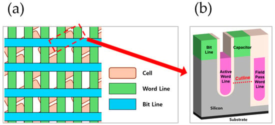
Figure 1.
(a) Diagram of 6F2 DRAM array top view; (b) 3D structure of 6F2 DRAM cell array with cutline.
In this study, we propose a 6F2 structure with buried oxide under the active word line that protects the energy field from the FPWL to mitigate the PGE. To find the optimal value, we studied various modifications to the buried oxide, such as increasing oxide thickness, increasing oxide length, and decreasing the distance from the AWL to the buried oxide. Additionally, by adding interface traps to the buried oxide, we were able to conduct a study about the effect of traps. Figure 1a illustrates a diagram of the 6F2 DRAM array at the top view, and Figure 1b shows a cross-section of the cell indicated by a red dotted line.
2. Simulation Methods
2.1. PGE Measurement
When FPWL is in an on state, the applied voltage generates an energy field, causing the energy band of the AWL to be lowered. Thus, the charge flows at a lowered voltage, which is expressed as a lowered threshold voltage (Vth). Through this phenomenon, the PGE value is calculated by the difference in FPWL’s Vth from an off state to an on state. The purpose of our study is to prevent the AWL from reaching the electric field of FPWL. Figure 2 shows the energy band and the Id–Vg curve as they change with the on and off states of the Field Pass Word Line.
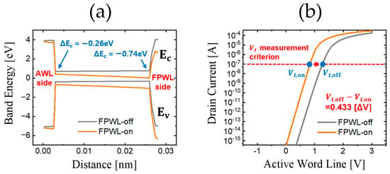
Figure 2.
Changes in the FPWL based on the on state and off state. (a) Energy band along the cutline of Figure 1b. (b) Drain current according to the voltage of the Active Word Line.
2D DRAM models were simulated using SILVACO TCAD simulation (DeckBuild version 5.2.17.R and DevEdit version 2.8.26.R). Table 1 shows the structure condition and the simulation condition. Every value is based on the 6F2 DRAM structure, which is precisely widely used. Figure 3 illustrates the buried oxide under the active word line in a 2D DRAM structure. To find the optimal value, we modified the buried oxide by changing the size or lowering the distance from the AWL.

Table 1.
Simulation conditions.
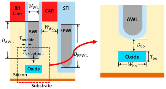
Figure 3.
The location and parameters of the buried oxide.
The silicon body was doped with boron at a concentration of 1017 cm−3, and the AWL and FPWL utilized an STI structure with SiO2. All these conditions replicate the structure using a saddle fin [,,,,,,,,,,].
2.2. Optimizing Buried Oxide
To investigate the tendency of the PGE based on the form of buried oxide, it is necessary to set a structural standard. So, we set the initial values for buried oxide to have a width of 28 nm, a thickness of 30 nm, and a distance of 18 nm from the AWL to the buried oxide. The buried oxide is positioned directly beneath the word line and aligned in the same direction as the word line. Its material is based on SiO2. Table 2 shows the parameters and steps of buried oxide, and Figure 3 illustrates the location and parameters of buried oxide. Using the initial values we set, we conducted a study on modifying buried oxide by lowering the distance (Dbo), increasing the width (Wbo), and increasing the thickness (Tbo). The tendencies of PGE values were verified by extracting 5 results for each modification, and we finally verified how much the PGE value had decreased.

Table 2.
Conditions and steps of buried oxide.
The Dbo was measured by moving 4 nm closer to the AWL at each step. Although theoretically, this could result in five measurements, starting from 18 nm and reducing to 2 nm, the 2 nm interval is challenging to achieve with current technology. Therefore, instead of including the 2 nm measurement, a result at 22 nm was added to provide a clearer trend, starting from 18 nm and increasing by 4 nm. The Wbo was increased by 4 nm in total for each step, with 2 nm added to both the left and right sides. Similarly, for the Tbo, the thickness was increased by 4 nm in total, with 2 nm added above and below. Figure 4 illustrates the changes in the buried oxide for each case.

Figure 4.
Modifications of each parameter of the buried oxide. (a) Adjustment of Dbo; (b) adjustment of Wbo; (c) adjustment of Tbo.
2.3. Effect of Interface Traps in Buried Oxide
The primary objective of the buried oxide is to mitigate the Pass Gate Effect (PGE). Therefore, it is critical that the addition of this structure does not inadvertently worsen the PGE. However, at the interface where Si meets amorphous SiO2, incomplete bonds in some Si atoms lead to the formation of positive charges, creating interface traps. These traps decrease the threshold voltage (Vth), negatively affecting the PGE. As a result, preventing the formation of interface traps during the deposition of the buried oxide is essential. To better understand how interface traps influence the PGE, we varied the trap density and analyzed the corresponding changes in the PGE values.
3. Results
To verify the effectiveness of the buried oxide, we first compared the PGE of the existing structure with the new structure. In the existing structure, the value was 1.269 V, and the value was 0.837 V, resulting in a final PGE of 0.433 []. In the structure with the added buried oxide, the value was 1.173 V, and the value was 0.762 V, yielding a PGE of 0.411 []. This indicates a reduction in the PGE of approximately 5.04% due to the addition of the oxide. Table 3 shows the differences in PGE and Vth with and without buried oxide, and Figure 5 shows the PGE difference with and without the buried oxide.

Table 3.
Difference in PGE and threshold voltage with and without buried oxide.
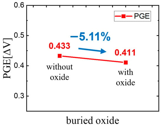
Figure 5.
PGE difference with and without the buried oxide.
When voltage is applied to the FPWL, it enters the on state, forming an electric field that lowers the energy band of the AWL, thereby reducing the threshold voltage. The addition of buried oxide restricts the channel area formed in the AWL, thereby strengthening gate control. This effect contributes to the reduction in threshold voltage, which is a key mechanism for mitigating the PGE.
As previously mentioned, we attempted to carry out modifications to find the optimized form of the oxide. Adjusting Dbo, Wbo, and Tbo all led to a reduction in the PGE. Among these, adjusting Dbo resulted in the highest reduction rate per step, followed by increasing Tbo and Wbo. For Dbo, starting from the initial buried oxide value of 18 nm with a PGE value of 0.411 [ΔV] and reducing the distance to 6 nm resulted in a decrease to 0.390 [ΔV]; this represents a 5.11% reduction in the PGE. Similarly, the reduction rates observed when modifying Tbo and Wbo were 4.14% and 3.65%, respectively. In all cases, the reduction trend was nearly linear, highlighting the importance of positioning the oxide layer at an optimal size and location to achieve significant PGE reduction while maintaining manageable fabrication complexity.
Table 4 shows the Vt,off, Vt,on, and PGE values when adjusting the parameters of the buried oxide, while Figure 6 presents a graph illustrating the trend of PGE values based on the changes in the buried oxide parameters.

Table 4.
Threshold voltage and PGE values when adjusting the parameters of the buried oxide.

Figure 6.
PGE results of buried oxide for each modification. (a) Reducing Dbo; (b) increasing Tbo; (c) increasing Wbo.
Various modifications to the buried oxide further increase this gate control, although further research is needed to fully understand the underlying causes. If the exact cause of PGE reduction is identified, a more optimized form of the buried oxide can be developed.
As expected, the results from adding interface traps showed an increase in the PGE. When the trap density ranged from 1010 to 1011 [cm−2], the PGE value showed a slight increase from 0.4112 to 0.4118 [ΔV]. However, within the 1011 to 1012 [cm−2] range, the PGE value sharply increased from 0.4118 to 0.4385 [ΔV]. This suggests that while a certain level of traps can be ignored, it is crucial to eliminate traps beyond a certain threshold to maintain the effectiveness of the buried oxide in mitigating PGE. Table 5 shows the Vt,off, Vt,on, and PGE values based on the interface trap density of the buried oxide, while Figure 7 graphically represents the trend of PGE values as the interface trap density of the buried oxide. The reason PGE increases with trap concentration is that, as trap concentration increases, gate controllability decreases; this leads to a significant influence from adjacent word lines. When the trap concentration increases above 1011 [cm−2], the PGE rises abruptly, indicating that the trap density should be kept below 1011 [cm−2].

Table 5.
Threshold voltage and PGE values when adjusting the interface trap density of the buried oxide.
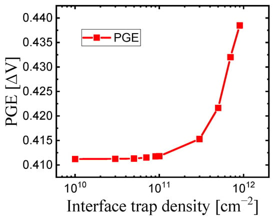
Figure 7.
The trend of PGE values with increasing interface trap density of the buried oxide.
4. Conclusions
In this study, we simulated a structure in which an oxide layer was buried beneath the AWL to reduce the PGE occurring in DRAM. To find the optimal oxide configuration, various modifications were tested. Among them, reducing the distance between the AWL and the oxide showed the highest PGE reduction rate, followed by increasing Tbo and widening Wbo. The trend of PGE reduction was nearly linear, emphasizing the importance of selecting the appropriate size and location for the oxide layer. Additionally, the results demonstrated that increasing the density of interface traps leads to a corresponding increase in the PGE, underscoring the importance of eliminating traps during the fabrication of such structures. The results confirmed that the buried demonstrates a significant reduction in the PGE.
Author Contributions
Conceptualization, Y.-S.K.; methodology, Y.-S.K. and M.-W.K.; software, Y.C. and Y.-S.K.; validation, Y.-S.K. and M.-W.K.; formal analysis, Y.C., Y.-S.K. and M.-W.K.; investigation, Y.C. and Y.-S.K.; resources, M.-W.K.; data curation, Y.C. and Y.-S.K.; writing—original draft preparation, Y.C.; writing—review and editing, Y.C., Y.-S.K. and M.-W.K.; visualization, Y.C.; supervision, M.-W.K.; project administration, M.-W.K.; funding acquisition, M.-W.K. All authors have read and agreed to the published version of the manuscript.
Funding
This research was supported by the National R&D Program through the National Research Foundation of Korea (NRF) funded by the Ministry of Science and ICT (NRF-2022M3I7A1078936) and also this research was supported by “Regional Innovation Strategy (RIS)” through the National Research Foundation of Korea (NRF) funded by the Ministry of Education (MOE) (2022RIS-005).
Institutional Review Board Statement
Not applicable.
Informed Consent Statement
Not applicable.
Data Availability Statement
The original contributions presented in the study are included in the article, further inquiries can be directed to the corresponding author.
Conflicts of Interest
The authors declare no conflict of interest.
References
- Kim, Y.-S.; Lim, C.-Y.; Kwon, M.-W. Reduction of the Pass Gate Effect with a Spherical Shallow Trench Isolation in the BCAT Structure. J. Semicond. Technol. Sci. 2023, 23, 236–242. [Google Scholar] [CrossRef]
- Kim, Y.S.; Lim, C.Y.; Kwon, M.W. Mitigating WL-to-WL Disturbance in Dynamic Random-Access Memory (DRAM) through Adopted Spherical Shallow Trench Isolation with Silicon Nitride Layer in the Buried Channel Array Transistor (BCAT). Electronics 2024, 13, 681. [Google Scholar] [CrossRef]
- Sun, Y.; Liu, X.; Wang, N.; Jeon, J.; Wu, B.; Cao, K. Trap-Assisted Passing Word Line Leakage and Variable Retention Time in DRAM. In Proceedings of the 4th International Conference on Electronics Technology (ICET), Chengdu, China, 7–10 May 2021. [Google Scholar] [CrossRef]
- Yuan, X.; Park, J.-E.; Wang, J.; Zhao, E.; Ahlgren, D.C.; Hook, T. Gate-Induced Drain-Leakage Current in 45-nm CMOS Technology. IEEE Trans. Device Mater. Reliab. 2008, 8, 501–508. [Google Scholar] [CrossRef]
- Lim, K.Y.; Yu, X.; Yeo, D. A study on gate-induced junction breakdown. In Proceedings of the 6th International Conference on Solid-State and Interated Circuit Technologly, Shanghai, China, 22–25 October 2001. [Google Scholar] [CrossRef]
- Lo, G.Q.; Joshi, A.B. Hot-carrier-stress effects on gate-induced drain leakage current in n-channel MOSFETs. IEEE Electron Device Lett. 1991, 12, 5–7. [Google Scholar] [CrossRef]
- Chang, C.; Haddad, S.; Swaminathan, B.; Lien, J. Drain-avalanche and hole-trapping induced gate leakage in thin-oxide MOS device. IEEE Electron Device Lett. 1988, 9, 588–590. [Google Scholar] [CrossRef]
- Yang, T.; Lin, X.-W. Trap-Assisted DRAM Row Hammer Effect. IEEE Electron Device Lett. 2019, 40, 391–394. [Google Scholar] [CrossRef]
- Son, M.; Park, H. Making DRAM strong against row hammering. In Proceedings of the 54th ACM/EDAC/IEEE Design Automation Conference (DAC), Austin, TX, USA, 18–22 June 2017. [Google Scholar] [CrossRef]
- Kim, Y.; Daly, R.; Kim, J.; Fallin, C.; Lee, J.H.; Lee, D.; Wilkerson, C.; Lai, K.; Mutlu, O. Flipping bits in memory without accessing them: An experimental study of DRAM disturbance errors. ACM SIGARCH Comput. Archit. News 2014, 42, 361–372. [Google Scholar] [CrossRef]
- Bhati, I.; Chang, M.-T.; Chishti, Z.; Lu, S.-L.; Jacob, B. DRAM Refresh Mechanisms, Penalties, and Trade-Offs. IEEE Trans. Comput. 2016, 65, 108–121. [Google Scholar] [CrossRef]
- Im, J.; Kim, H.; Kim, J.; Woo, S.; Kwon, T.; Yoon, Y.J. Analysis of Row Hammer and Passing Gate Effect in DRAM Cells by BCAT Structural Design. In Proceedings of the 2024 IEEE Silicon Nanoelectronics Workshop (SNW), Honolulu, HI, USA, 15–16 June 2024; pp. 91–92. [Google Scholar] [CrossRef]
- Kim, H.; Im, J.; Kim, J.; Woo, S.; Kwon, T.; Yoon, Y.J. Investigation of Row Hammer and Passing Gate Effects Based on the Work Functions of Dual Gates in DRAM Cells. In Proceedings of the 2024 IEEE Silicon Nanoelectronics Workshop (SNW), Honolulu, HI, USA, 15–16 June 2024; pp. 89–90. [Google Scholar] [CrossRef]
- Park, S.-W.; Hong, S.-J.; Kim, J.-W.; Jeong, J.-G.; Yoo, K.-D.; Moon, S.-C. Highly scalable saddle-Fin (S-Fin) transistor for sub-50 nm DRAM technology. In Proceedings of the 2006 Symposium on VLSI Technology, Honolulu, HI, USA, 13–15 June 2006. Digest of Technical Papers. [Google Scholar]
- Han, J.-W.; Suh, M.; Lee, G.; Kim, J. Overhang saddle fin sidewall structure for highly reliable DRAM operation. IEEE Access 2023, 11, 82738–82743. [Google Scholar] [CrossRef]
- Liu, X.; Sun, Y.; Wang, N.; Jeon, J.; Wu, B.; Cao, K. Saddle Fin Structure Effects on the DRAM Access Transistor Performance. In Proceedings of the IEEE 4th International Conference on Electronics Technology (ICET), Chengdu, China, 7–10 May 2021. [Google Scholar]
- Kim, Y.K.; Lee, J.S.; Kim, G.; Park, T.; Kim, H.J.; Cho, Y.P.; Park, Y.J.; Lee, M.J. Partial isolation type saddle-FinFET (Pi-FinFET) for sub-30 nm DRAM cell transistors. Electronics 2018, 8, 8. [Google Scholar] [CrossRef]
- Liu, X.; Sun, Y.; Li, D.; Jeon, J.; Wu, B. TCAD Simulation on Saddle-Fin Device Performance Boosting with Word Line Engineering. In Proceedings of the 6th International Conference on Electronics Technology (ICET), Chengdu, China, 12–15 May 2023. [Google Scholar]
- Gautam, S.K.; Manhas, S.K.; Kumar, A.; Pakala, M. Mitigating the Passing Word Line Induced Soft Errors in Saddle Fin DRAM. IEEE Trans. Electron Devices 2020, 67, 1902–1905. [Google Scholar] [CrossRef]
- Han, J.-W.; Kim, J.; Moon, D.-I.; Lee, J.-S.; Meyyappan, M. Soft Error in Saddle Fin Based DRAM. IEEE Electron Device Lett. 2019, 40, 494–497. [Google Scholar] [CrossRef]
- Yang, C.-M.; Wei, C.-K.; Chang, Y.J.; Wu, T.-C.; Chen, H.-P.; Lai, C.-S. Suppression of Row Hammer Effect by Doping Profile Modification in Saddle-Fin Array Devices for Sub-30-nm DRAM Technology. IEEE Trans. Device Mater. Reliab. 2016, 16, 685–687. [Google Scholar] [CrossRef]
- Jeon, S.; Choi, J.; Jung, H.-C.; Kim, S.; Lee, T. Investigation on the local variation in BCAT process for DRAM technology. In Proceedings of the IEEE International Reliability Physics Symposium (IRPS), Monterey, CA, USA, 2–6 April 2017; pp. FA-4.1–FA-4.2. [Google Scholar] [CrossRef]
- Suh, M.; Ryu, M.; Ha, J.; Bang, M.; Lee, D.; Kim, J. Design Guideline of Saddle-Fin-Based DRAM for Mitigating Rowhammer Effect. IEEE Trans. Electron Devices 2024, 71, 2417–2422. [Google Scholar] [CrossRef]
- Kim, S.; Kim, D.Y.; Park, J.W.; Kim, S.; Lee, S.; Jang, H.S.; Park, J.; Yoo, S.; Lee, M.J. Passing Word Line-Induced Subthreshold Leakage Reduction Using a Partial Insulator in a Buried Channel Array Transistor. IEEE Trans. Electron Devices 2024, 71, 2976–2982. [Google Scholar] [CrossRef]
Disclaimer/Publisher’s Note: The statements, opinions and data contained in all publications are solely those of the individual author(s) and contributor(s) and not of MDPI and/or the editor(s). MDPI and/or the editor(s) disclaim responsibility for any injury to people or property resulting from any ideas, methods, instructions or products referred to in the content. |
© 2024 by the authors. Licensee MDPI, Basel, Switzerland. This article is an open access article distributed under the terms and conditions of the Creative Commons Attribution (CC BY) license (https://creativecommons.org/licenses/by/4.0/).