1. Introduction
With the rapid change in climate conditions, the phenomena associated with strong winds are becoming more dangerous. Moreover, early wind prediction is also becoming more difficult. An example is the category 5 Hurricane Otis [
1], which devastated Acapulco city in Mexico on 25 October 2023. At the very beginning, this hurricane was estimated as only a tropical storm, but unexpectedly, it became an unusually strong hurricane. The wind blew at 265 km/h. Sudden gusts of wind were even stronger. The observed wind gust speed was equal to 330 km/h. Equally dangerous weather phenomena also occur in previously moderate climate zones. At the beginning of November 2023, Europe was hit by Hurricane Ciaran [
2]. The wind gust speed exceeded 200 km/h. In such conditions, all types of lifting equipment, such as scissor lifts, elevating work platforms of different kinds, and cranes, including tower cranes, are particularly vulnerable to destruction [
3,
4,
5,
6,
7,
8,
9,
10,
11]. This paper examines the problem of the wind load acting on the gantry crane, particularly how strong the wind must be to cause the whole structure to tip over. Gantry cranes seem very stable and resistant to strong gusts of wind. However, cases of this type of structure overturning due to strong winds have been known to occur [
12,
13].
The wind load is considered one of the most important loads in the design process. It is found in many codes, such as [
14,
15,
16,
17,
18,
19]. The European Standard ISO-4302 [
14] (like the other cited standards) concerns wind loading in cranes. According to the standard, if the wind blows at a constant speed from any horizontal direction, it will cause a quasi-static uniform load (pressure) on the investigated structure. This approach should be treated as a relatively simple method. The calculation method also considers redundancy qualities, considering the effects of gusts (rapid changes in wind speed) and the dynamic response of the crane structure. When calculating wind for cranes, two load states are considered.
The first is the wind load for cranes in the working state. This is the highest wind load that acts on the crane during its operation and for which it was designed. The wind load is assumed to act from the least favorable direction in combination with other operating loads. According to the code [
14], the operating state wind speeds and corresponding pressures are as follows: if the crane manufacturer has not adopted and specified other values in the crane’s operating instructions, then, in the case of normal cranes working in open space, the design wind speed is equal to
V = 20 m/s, and the corresponding wind design wind pressure is
p = 250 N/m
2, whereas in the case of cranes that must work in high winds, the design wind speed and design wind pressure are equal to
V = 28.5 m/s and
p = 500 N/m
2, respectively.
The second crane load condition, according to [
14], is the wind load on cranes in the non-working state. This is the strongest (storm) wind gust load from the least favorable direction that acts on the crane in the non-working state and for which the crane was designed. The wind speed is variable and depends on the geographic location and the degree of exposure of the crane to the wind.
Regardless of the code, however, the following equation is used to calculate wind load
F of the entire crane, its parts, and individual structural elements [
14]:
where
A is the effective frontal area of the part under consideration in m
2, i.e., the area of the projection of all elements on a plane, which is perpendicular to the wind direction;
p denotes the wind pressure; and
Cf is the streamlining coefficient of the part under consideration in the direction of the wind action.
When calculating the wind load of a crane in a non-swinging state, the wind pressure is assumed to have a constant value in each 10 m vertical height interval of the crane. Alternatively, wind pressure can be calculated at locations at any height, or a constant value of wind pressure calculated for the highest point on the structure can be assumed.
The resultant wind load acting on a structure is the sum of the loads on the individual components. In the case when the direction of the wind is not parallel to the longitudinal axis of the component or frame surface, the magnitude of the aerodynamic force is estimated with the use of the following expression:
in which
θ is the angle between the wind direction and the longitudinal axis or surface (
θ < 90°). However, it should be stressed that the approach presented in the mentioned standards could be inadequate compared to real-life conditions. This is mainly due to different additional phenomena like vibrations, interference with the neighboring buildings and structures, etc. Therefore, works that report the results of the measured wind conditions performed on real-scale structures are very important [
20,
21,
22]. Next, these results are the basis for creating appropriate conditions in the aerodynamic tunnels, where the scaled models or parts of real-scale structures are investigated [
23,
24,
25,
26].
The rapid evolution of finite element software enables performing numerical analyses of more and more complicated problems which concern the phenomena of the airflow around and through crane-like engineering structures for different wind profiles [
27,
28,
29]. Further mechanical analysis is possible when the distribution of the wind-induced load on the analyzed structure is available. Finally, the displacement or stress distribution in the most important nodes of the structure can be estimated [
30]. However, other approaches in computer science are also developed to determine the stability margin during lift operations, for example, Romanello [
31]. El Ouni et al. [
32] proposed and designed an active system of actuators and sensors for the mitigation of the dangerous effects of wind on the crane. Chen et al. [
33] prepared a mathematical model for the evaluation of the wind coefficients for the tower crane.
As mentioned above, a particularly dangerous situation is when a sudden gust of wind acts on the crane structure with a payload during the operation service, for example, as demonstrated by Skelton et al. [
34] and Cekus et al. [
35,
36].
The direct motivation for this work is the below-described accidents. It is worth noting that the wind damage, primarily involving cranes being blown along rails, is the highest damage cost. For example, in the accident at the LNG gas terminal in Świnoujście (Poland) in 2017 [
37], not only the crane was damaged but also the critical infrastructure in the immediate vicinity. The dome of the eastern gas tank and a section of the pipeline were damaged. An example of a gantry crane accident with a box girder, which was destroyed due to exceptionally high wind, is a large gantry crane at the Damen ship repair yard in Schiedam, near Rotterdam, The Netherlands, in 2018 [
38]. According to media information, the crane was properly secured, but one side of the crane began moving, causing a twist that broke the girder away from its supports. Witnesses to this event claim that the high winds may have created a localized tornado effect. Another accident involves the case of the gantry crane with a truss girder described in the work of Frendo [
13].
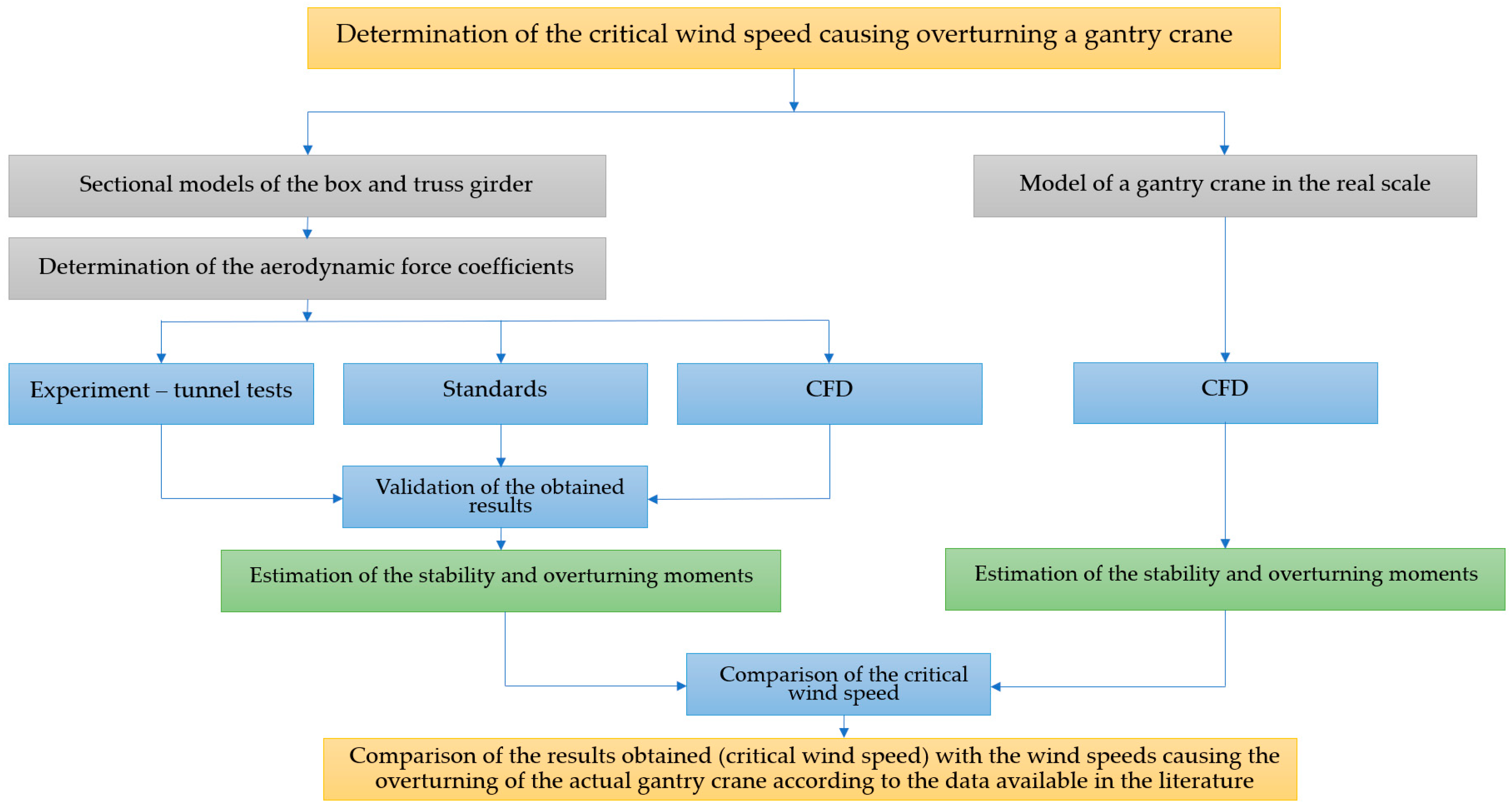
In the present work, two kinds of gantry cranes are studied: a gantry with a box girder and a gantry with a truss girder. For both structures, we prepared the scaled sectional models of the main horizontal girders (box girder and truss girder). Next, we performed experimental tests in the aerodynamic tunnel to estimate the horizontal and vertical aerodynamic coefficients of these models. The results of these tests were exploited to verify these results, which were obtained from CFD simulations. After, computations were performed for the real structure, namely a gantry crane with a box girder, when the numerical model was verified. These calculations aim to evaluate the magnitude of the wind speed, which causes the whole structure to tip over. An appropriate research framework diagram is depicted in
Figure 1.
It should be stressed that performing the CFD simulation is very difficult for gantry cranes with the horizontal truss girder. It is mainly caused by the fact that the appropriate mesh must consist of a significantly large number of elements with proper geometry. Often, it is very difficult; therefore, the aerodynamic forces and wind speed causing overturning for this kind of structure are estimated based on the sectional model. The obtained results are confronted with appropriate standards. It should be noted that this work is a continuation of the problems presented in the previous papers [
38,
39].
5. Conclusions
This article covers the maximum wind speed at which a gantry crane remains stable. According to the standard [
14], the maximum design wind speed
V is 20 m/s for all cranes installed in the open. Experimental testing and numerical analysis showed compliance with the standard regarding the stability behavior of this type of structure in open space at an average wind speed of 20 m/s. This study assumed that the gantry crane is stopped but not anchored to the rails on which it moves. For cranes installed in coastal areas, the wind situation is different. The standard states that overhead cranes that must continue to operate in high winds have a maximum design wind speed of 28.5 m/s (102.6 km/h), such as container cranes. In this case, the wind speed for such a facility can range from 20 m/s to 40 m/s (wind speed with gusts of 3 s).
As is reported from the data presented in this paper, the gantry crane with the truss horizontal girder can be overturned at 32.2 m/s (115.92 km/h) of wind speed. On the other hand, the gantry crane with the box girder can be overturned even at 37.45 m/s (134.75) of wind speed. The critical wind speed values obtained from CFD simulations for three different wind profiles and a box girder crane are almost identical and do not depend much on the type of terrain, and the obtained values are V1 = 41.445 m/s (149.202 km/h) for urban terrain, V2 = 41.278 m/s (148.602 km/h) for village terrain, and V3 = 41.020 m/s (147.672 km/h) for the open terrain, which are slightly higher than those determined according to the standards. In other words, estimations based on the standards provide underestimated critical wind speed values; thus, they are safe.
Although the standards provide the magnitudes of the moments regardless of wind direction, the results reported in the current work show significant differences due to the variation in the angle theta. The change in angle theta means that the wind direction is not parallel to the horizontal plane.
Wind strength depends mainly on the geographical location and the degree of wind exposure of the crane, as evidenced by the gantry crane accidents given in the Introduction, among others, including a box crane at the LNG terminal in Swinoujscie [
37] (coastal area) and the truss girder crane example described by Frendo [
13], where the gantry crane derailed and collapsed after traveling about 60 m in very strong winds of about 30.56 m/s (110 km/h). The given gantry crane disaster examples caused by high winds occurred when the wind speed was comparable to the values reported in this paper.
In this study, the authors wanted to draw attention to the importance of changing wind direction in the vertical plane. Usually, the change in wind direction is considered in the horizontal plane. However, as shown in the results, even a small change in the vertical angle, e.g., only up to 6°, causes significant changes in the value of the overturning moment (for selected angles). Thus, we wanted to show that adopting standard calculations for overhead cranes, which are usually located in urban or non-urban areas but not far from the city, can often lead to accidents, especially when the crane is operated in a coastal (seaside) area.


