Article

Synthesis of Porous Carbon Nanomaterials from Vietnamese Coal: Fabrication and Energy Storage Investigations

1
Chemistry Faculty, Thai Nguyen University of Education, Thai Nguyen 250000, Vietnam
2
Institute Academy of Military Science and Technology, Ha Noi 100000, Vietnam
3
International School, Thai Nguyen University, Thai Nguyen 250000, Vietnam
4
Institute of Applied Technology and Sustainable Development, Nguyen Tat Thanh University, Ho Chi Minh 700000, Vietnam
*
Authors to whom correspondence should be addressed.
Appl. Sci. 2024, 14(3), 965; https://doi.org/10.3390/app14030965
Submission received: 12 October 2023 / Revised: 12 December 2023 / Accepted: 21 December 2023 / Published: 23 January 2024
(This article belongs to the Special Issue Advances and Challenges in Biomass and Carbon Materials)

Abstract

:
The choice of precursor and simple synthesis techniques have decisive roles in the viable production and commercialization of carbon products. The intense demand for developing high-purity carbon nanomaterials through inexpensive techniques has promoted the usage of fossil derivatives as a feasible source of carbon. In this study, Vietnamese-coal-derived porous carbon (PC) was used to fabricate coal-derived porous carbon nanomaterials (CDPCs) using the modified Hummers method. The resulting porous carbon nanomaterials achieved a nanoscale structure with an average pore size ranging from 3 to 10 nm. The findings indicate that CDPC exhibits well-developed micropores and mesopores. The presence of macropores and mesopores not only facilitates the complete immersion of the material in the electrolyte but also effectively shortens the ion diffusion pathways. CDPC boasts a high carbon content, constituting 80.88% by weight. Electrochemical impedance spectroscopy (EIS) Nyquist plot of electrodes made from CDPC showed good conductivity value with low charge-transfer resistance. This electrode worked well and stably with capacitance retention of 74.7% after 1000 cycles. The CDPC specific capacitance reached 236 F/g under a current density of 0.1 A using the constant current discharge method and then decreased as the current density increased. Based on the results of the electrochemical properties of the materials, the energy storage capacity of the CDPC material was good and stable. This investigation presents an eco-friendly methodology for the judicious utilization of coal in energy storage applications, specifically as electrodes for supercapacitors and anodes for Li-ion batteries.

1. Introduction

Over the years, alongside classical carbon forms like the hardest and electrically insulating diamond and the softest and electrically conducting graphite, various novel carbon allotropes have been progressively discovered and developed, forming a new family of carbon materials. This family includes zero-dimensional fullerenes and carbon dots, one-dimensional carbon nanotubes and carbon fibers, and two-dimensional graphene, and graphyne, along with their derivatives [1,2]. Impressively, these carbon materials showcase numerous distinctive properties, such as a large specific surface area, tunable porosity, chemical surface functionality, exceptional thermal and electrical conductivity, mechanical and chemical stability, and diverse structures, rendering them highly promising materials for future applications [3,4].
While carbon nanomaterials hold great promise for various applications, the cost-effective and environmentally friendly production of these materials poses a considerable challenge. Traditional manufacturing methods for graphene, carbon nanotubes, and other nanostructured carbon materials frequently rely on expensive carbon precursors and resource-intensive processes [5,6]. Consequently, the commercial viability and widespread application of carbon materials are impeded by elevated production costs. Therefore, careful consideration must be given to the choice of carbon precursors and synthesis methods in the context of fabricating nanostructured carbon materials.
Coal, a fossil fuel originating from the remnants of ancient plants subjected to high pressure and temperature within the Earth’s crust, undergoes a series of transformations over millions of years to give rise to the coal deposits found today. Acknowledged for its high energy density, ease of storage, and cost-effectiveness, carbonaceous coal stands as a fundamental and economically viable energy source. Characterized as a naturally occurring heterogeneous macromolecular material, coal possesses a three-dimensional cross-linked architecture. The organic macromolecules within coal consist of a specific number of alicyclic and aromatic/hydroaromatic nuclei connected by short aliphatic and ether linkages [7,8,9,10,11].
Currently, within the electric industry, the stability of cycles in coke or hard carbon as an anode has been well documented, while graphite electrodes showcase high energy density and exceptional capacity. The exploration of synthesizing soft and environmentally friendly carbon materials, such as nanocarbon derived from coal and coke, stands as a promising research avenue. This is attributed to its potential to yield high-quality materials at a low cost, along with advantages like environmental friendliness, mild processing conditions, and scalability [12,13,14,15].
Several methods have been applied, depending on the desired properties of the final nanocarbon products. Zhou et al. [16] synthesized graphene and graphene-based metal materials from coal by using catalytic graphitization, chemical oxidation, and oxygen-reduction-assisted plasma dielectric barrier discharge (DBD). This method converts carbon atoms into a more graphitic form with increased strength and conductivity. Another method known as chemical oxidation was used by Nithin Joseph Panicker et al. [17] to synthesize oxidized graphene from graphite (HOG) with H2SO4 and HNO3 as the first oxidizing agents and KMnO4 as the last oxidizing agent. This process occurred within 3.5 h, producing oxygen-containing functional groups on the surface of the carbon. The as-synthesized HOG was more hydrophilic and dispersed easily in aqueous solutions, and it was more oxidized than GO prepared using the Hummers method. Yaxiong Liu [18] successfully fabricated the positive electrode in a Li-ion battery from coke activated by HF and HCl and then calcined at 600 °C and 900 °C for 1 h. Seung Eun Lee et al. [19] fabricated carbon materials from ordinary coke and calcined coke at 1300 °C. After one of these treatment methods, the material can be further processed to produce nanocarbon materials, such as graphene and carbon nanotubes using sonication, exfoliation, and hydrothermal synthesis.
Carbon is now used primarily in commercial lithium-ion battery anodes due to its advantageous properties such as widespread availability, outstanding electronic conductivity, low cost, and a favorable hierarchical arrangement for Li-ion insertion. Studies on carbon-based anode materials indicate that porous carbon has obvious advantages in providing high lithiation capability and excellent cycling stability. The existence of micropores and mesopores has exerted significant effects on the electronic structure and performance, such as the shortened transport length for Li ions and the largened electrode/electrolyte interface for the charge-transfer reaction [20]. Owing to its typical characteristic of a porous structure and its low cost, carbon is widely used for supercapacitor electrodes [21,22,23,24] and catalytic supports [25,26,27] and also possesses the potential to be used as an anode material in lithium-ion batteries (LIBs). Hao et al. [28] achieved the successful synthesis of porous carbon nanosheets (PCNS1000) from pitch and coal. PCNS1000, with a mesoporous structure featuring an average pore size of 5.7 nm, was utilized as an anode in lithium-ion batteries, showcasing a capacity of 270.0 mA h.g−1 at 0.1 A.g−1. In a recent development, Zhao et al. [29] effectively engineered a nano nanocomposite material (MoO3/CCNFs) using coal and acid-treated molybdenum. The MoO3/CCNF exhibited characteristics such as an increased specific surface area and volume of porous cavities, a result of the release of small gas molecules during the coal carbonization process. This attribute is advantageous for the movement of Li+ ions, mitigating volume stress caused by Li+ insertion during the charging process and fostering favorable conditions for electrode reaction kinetics.
Therefore, designing simple and productive approaches for the controllable synthesis of coal-based porous carbon is still a great challenge.
The coal reserves in Vietnam are estimated to be around 3.36 billion tons, comprising all types of coal: Anthracite, Fat Coal, Bituminous Coal, Brown Coal, and Peat. Vietnam is one of the three countries in Southeast Asia with the largest exploitable coal reserves. Hence, opting for an appropriate method to produce porous carbon materials from coal in Vietnam is a judicious direction, holding the promise of numerous successes at low costs while utilizing readily available resources.
Furthermore, the transition from fossil fuels to alternative energy sources necessitates the potential application of coal in more environmentally friendly domains. Moreover, although coal is a fossil fuel, the minute amount required in the energy transition sector makes this path highly feasible for a sustainable future.
This work presents the fabrication of nanoscale porous carbon materials from coal of the Coke Factory of Thai Nguyen Steel Joint Stock Company, Thai Nguyen Province, Viet Nam, using the improved Hummers method. Exploring the surface morphology, structure, composition, and surface area of the synthesized materials is essential. The electrochemical properties of the materials signify their potential for electron exchange and efficient energy storage. These preliminary findings hold promise, indicating the potential for the successful fabrication of lithium-ion batteries in Vietnam.

2. Materials and Methods

2.1. Chemicals

KOH (pellets), 98% H2SO4, 85% H3PO4, 99% KMnO4, and carbon nanotubes were purchased from Sigma Aldrich (St. Louis, MI, USA); 30% H2O2 and n-Butyl acetate were purchased from Meck (Darmstadt, Germany). Polytetrafluoroethylene was purchased from Chemours DuPont Co. (Wilmington, DE, USA), and 95% graphite powder was purchased from VCS Vietnam Technology Joint Sock Company (Ha Noi, Vietnam). Nickel foil was purchased from Gelon Lib. Co., Ltd. (Shandong, China).

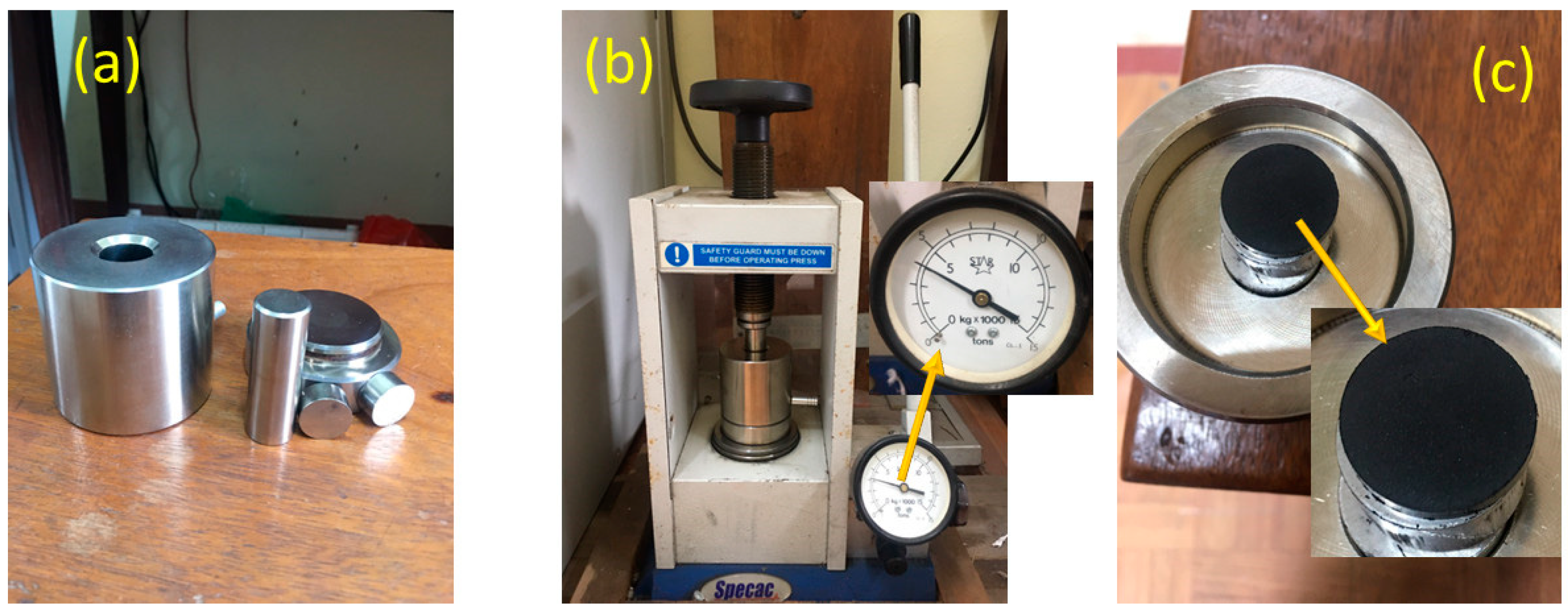
2.2. Fabrication of Porous Carbon Materials

The fabrication of porous carbon nanomaterials from coal followed a previous study with few modifications [17]. Coal taken from the Coke Factory of Thai Nguyen Iron and Steel Joint Stock Company with a size of 15 mm and ash content <15% was used as a starting material to make porous carbon materials. The coal was then ground and sieved into powder, and the resulting particle size of the coal powder (CP) was <0.5 mm. In a 500 mL container, 30 mL of H2SO4 acid solution (density: 1.84 g/mL) was combined with 10 mL of H3PO4 (density: 1.685 g/mL), and the mixture was subjected to magnetic stirring at 80 °C for 30 min. Then, 1 g of CP was added to the mixture, and stirring was continued for 1.5 h. Then, the sample was transferred to a basin of ice water to cool down, and 6 g of KMnO4 was slowly added to the sample over 30 min. The solution was then stirred at 45 °C for 1 h. Subsequently, 50 mL of distilled water and 4 mL of H2O2 were added to the solution, and the temperature was increased to 90 °C for 15 min. Finally, 36% HCl solution was added to the mixture, which was centrifuged several times and rinsed with distilled water until the washing solution reached pH = 7 [17]. Finally, the material was dried at 90 °C for 24 h and designed as porous carbon nanomaterial (CDPC).

2.3. The Morphology, Element Composition, and Structures of Materials

The morphology of CP and CDPC was investigated using an MS-7001F scanning electron microscope and a JEM-2001F transmission electron microscope (Jeol, Tokyo, Japan). The fraction of the material was determined by energy-dispersive spectroscopy (EDS) coupled with SEM. The mass reduction of the material was determined using the differential thermal analysis method using a TG-DTA 8121 (Rigaku, Osaka, Japan). The material structure was determined using the X-ray diffraction (XRD) method (D8 ADVANCE; Bruker, Bremen, Germany) and Raman spectroscopy (LabRAM HR Evolution; Horiba, Kyoto, Japan). The specific surface area of the material was determined using the Brunauer–Emmett–Teller (BET) method. SEM, TEM, and EDS measurements were performed at the Institute of Materials, Vietnam Academy of Science and Technology (Hanoi, Vietnam). DTA was performed at the Key Laboratory of Advanced Materials Applied in Green Development, University of Natural Sciences, Vietnam National University (Hanoi, Vietnam). BET analysis was performed at the Department of Chemistry, Hanoi Pedagogical University. Raman spectra were measured at the Center of Experiment and Practice, Thai Nguyen University of Science, Thai Nguyen University. Thermogravimetric analysis (TGA) was conducted using a differential thermal analysis and thermogravimetric analyzer (TG-DTA), model TG-DTA 8121, at the Department of Chemistry, Faculty of Natural Sciences, Hanoi National University.

2.4. Fabrication of Electrodes from Porous Carbon Materials

Electrodes made from coal materials included a mixture of CDPC, graphite, carbon nanotubes, and polytetrafluoroethylene (PTFE) at a 70:10:10:10 ratio mixed with an agate mortar. n-butyl acetate solvent was slowly added to dissolve the PTFE until the mixture reached a paste-like consistency. The mixture was poured on both sides of the nickel foil with a diameter of 1 cm and laminated with a thin film thickness of 200 um, and then it was loaded under the pressure of 5 tons for 5 min on a hydraulic press (Center of Experiment and Practice, Thai Nguyen University of Science, Thai Nguyen University). Figure 1a shows the electrode fabrication tools, Figure 1b illustrates the electrode compression process, and Figure 1c displays the resulting electrode product with a black surface. The electrode was dried in a vacuum oven at 80–110 °C for 12 h. The electrode was then immersed in 6M KOH solution for 12 h. The electrochemical properties of CDPC were measured in a 6M KOH aqueous electrolyte with a three-electrode supercapacitor cell at room temperature using an Autolab PSGTAT100 electrochemical system (Autolab, Tokyo, Japan) at the Department of Chemistry, Thai Nguyen University of Education, Thai Nguyen University. All chemicals used in the electrode fabrication and electrochemical property studies were pure chemicals.
The capacitance of the electrode was calculated using a cyclic voltammogram (CV) as shown in Equation (1):
C = E i E f I E d E 2 m v ( E f E i )  
where m is the mass of the material (g), v is scan rate (mV/s), (EfEi) is the potential range, and E i E f I ( E ) d E is the integrated charge in the graph.
The specific capacitance was calculated using the method of charging–discharging as prescribed in Equation (2):
C = 4 I t m V  
where I is the current density (A/g), Δt is the discharge time (s), and ΔV is the working voltage (V).

3. Results and Discussion

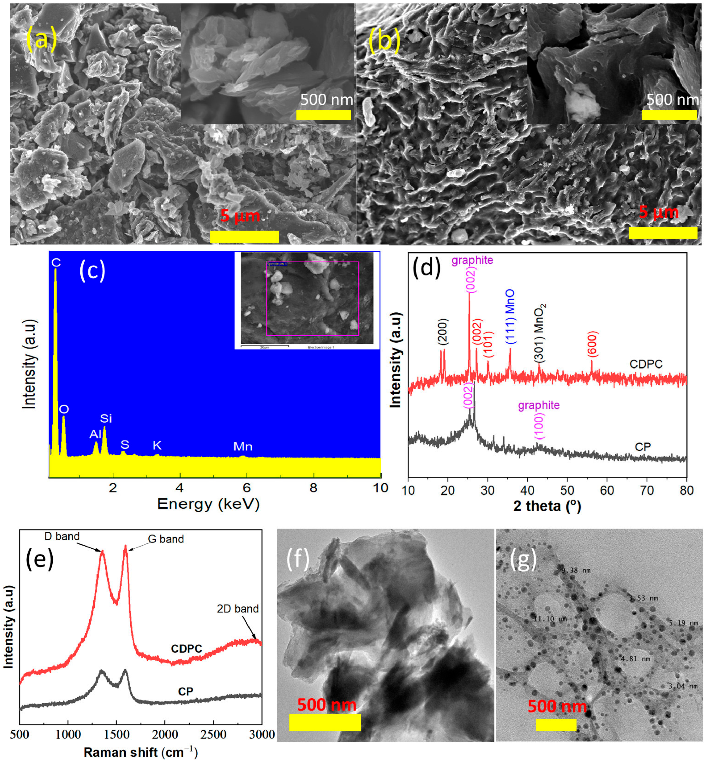
3.1. Physical Properties and Surface Characteristics of CP and CDPC

The thermal analysis results of the CP sample are depicted in Figure 2. As shown in Figure 2, the differential thermal analysis (DTA) curve exhibits two distinct exothermic peaks at temperatures of 318 °C and 597 °C. Simultaneously, the thermogravimetric (TG) analysis curve displays two stages of mass loss. The initial stage, occurring within the temperature range of roughly 500–650 °C and accounting for an 82.16% reduction in mass, is attributed to the combustion of constituents contained within the CP. Beyond 800 °C, the sample’s mass demonstrates a state of relative stability. It can be inferred that at this stage, the remaining components of coal oxide of low temperature at 800 °C are potentially intermixed with trace amounts of metal oxides found in the coal.
In Figure 3a,b, SEM images of CP and CDPC illustrate distinct surface morphologies between the two materials. Specifically, the CP material consists of particles with an average size of approximately 20–20 μm, while CDPC exhibits a structure characterized by small, porous pieces with a variety of mesopores and macropores.
From SEM images (Figure 3a,b), it can be observed that after oxidation, a rough surface with wrinkles and folds is formed, which was the result of deformation upon the exfoliation and restacking processes. These changes in morphology can be due to sp3 carbons and various GO structural defects like the formation of oxygen-containing functional groups in the basal planes [17]. The existence of macropores and mesopores will not only assist electrolytes in penetrating the materials in full depth but also shorten the ion diffusion paths effectively. The micropores could further provide more active sites for the insertion of lithium ions [30]. Figure 3f is a TEM image of CDPC, displaying a richer porous structure and more even pore size distribution. The sheet-like structure of graphene at a higher resolution, as shown in Figure 3g, reveals that the porous carbon material has sizes ranging from 3 to 10 nm. The well-developed pore distribution, presence of numerous active sites, and appropriate migration channels for ions enhance the electrochemical parameters necessary for the fabrication of supercapacitors, batteries, and electrochemical sensors [6,12,18,19].
The EDX analysis results (presented in Figure 3c and Table 1) reveal that the primary constituents of the CDPC material are carbon with a content of 80.88% by weight, alongside trace amounts of various impurities, including oxygen, aluminum, silicon, sulfur, and manganese (Mn).
The XRD analysis presented in Figure 3d reveals distinct diffraction peaks for CP occurring at scattering angles between 20 and 30 degrees and weaker diffraction peaks between 41 and 45 degrees, corresponding to the (002) and (100) planes of disordered carbon. The narrower and sharper diffraction peaks of (002) and (100) signify a more ordered crystal structure of the carbon sample, with a higher degree of graphitization [31]. The CDPC phase composition is mainly graphite, along with phases of MnO, MnO2, and MnS. The obtained result is consistent with the above EDX analysis results.
Figure 3e shows the G-band of 1592 cm−1, which represents a shift to a larger wavenumber than that of graphite (1570 cm−1) due to graphite oxidation. The D-band (1349 cm−1) characterizes defect formation and distortion due to the presence of in-plane heteroatoms, grain boundaries, and aliphatic chains. On the other hand, at the 2D-band (2945 cm−1), this small and obtuse peak for CDPC is due to the disruption of the stacking order layers by the oxidation reaction [32]. Thus, it can be seen that the activation of CP to form CDPC dissociated the planes of graphite to form graphene and then oxidized it to form graphene oxide. The 2D-band peak CP (2945 cm−1) has a sharp peak and a high base, which are typical for defects. It is most likely that coal has many defects and CP has a highly disordered crystalline structure similar to that of the CDPC material.
Based on the BET (Brunauer–Emmett–Teller) method, the specific surface area of CP was calculated to be 4.1704 m2/g, while the specific surface area of CDPC is determined to be 33.9601 m2/g.
The nitrogen isotherm adsorption curves of CP and CDPC are shown in Figure 4a. The isotherm of adsorption for CP is a Type III isotherm according to the IUPAC classification. Type III isotherms are commonly associated with materials with a large pore size (d > 50 nm). In contrast, the adsorption and desorption isotherms of CDPC are Type IV isotherms, featuring a hysteresis loop of type H4 according to the IUPAC classification. The presence of the H4 hysteresis loop is often encountered in adsorbents exhibiting particle sizes spanning from microcapillary to medium pore dimensions. This observation is attributed to the nitrogen isotherm adsorption curves manifested within the relative pressure (P/P0) range of 0.40 to 0.90, which are associated with the adsorption process of particles possessing medium dimensions. Conversely, the curves discerned at P/P0 > 0.90 correspond to the adsorption behavior of particles characterized by microcapillary sizes. The BJH adsorption cumulative volume of pores between 1.7 nm and 300.0 nm is 0.3143 cm3 g−1 for CDPC and 0.0148 cm3 g−1 for CP. From the BET measurement results and SEM analysis of CP and CDPC materials, it is evident that there is a coexistence of mesopores and macropores within the CDPC. The surface area and the porous volume of CDPC are higher than those of CP, indicating that the acid activation process of CP has increased its ability to form a double-layer electric charge, thus enhancing the specific capacitance of CDPC.
Pore size is also a critical factor that determines the energy storage capacity of a material. The calculated pore diameter from the BET method for CDPC is 2.5 nm, which is suitable for the formation of a double-layer electric charge because it is larger than the size of ions in the KOH electrolyte. This result is consistent with those reported for other carbon materials in previous studies [31]. The above results show that CDPC has been successfully fabricated from CP using the modified Hummers method.

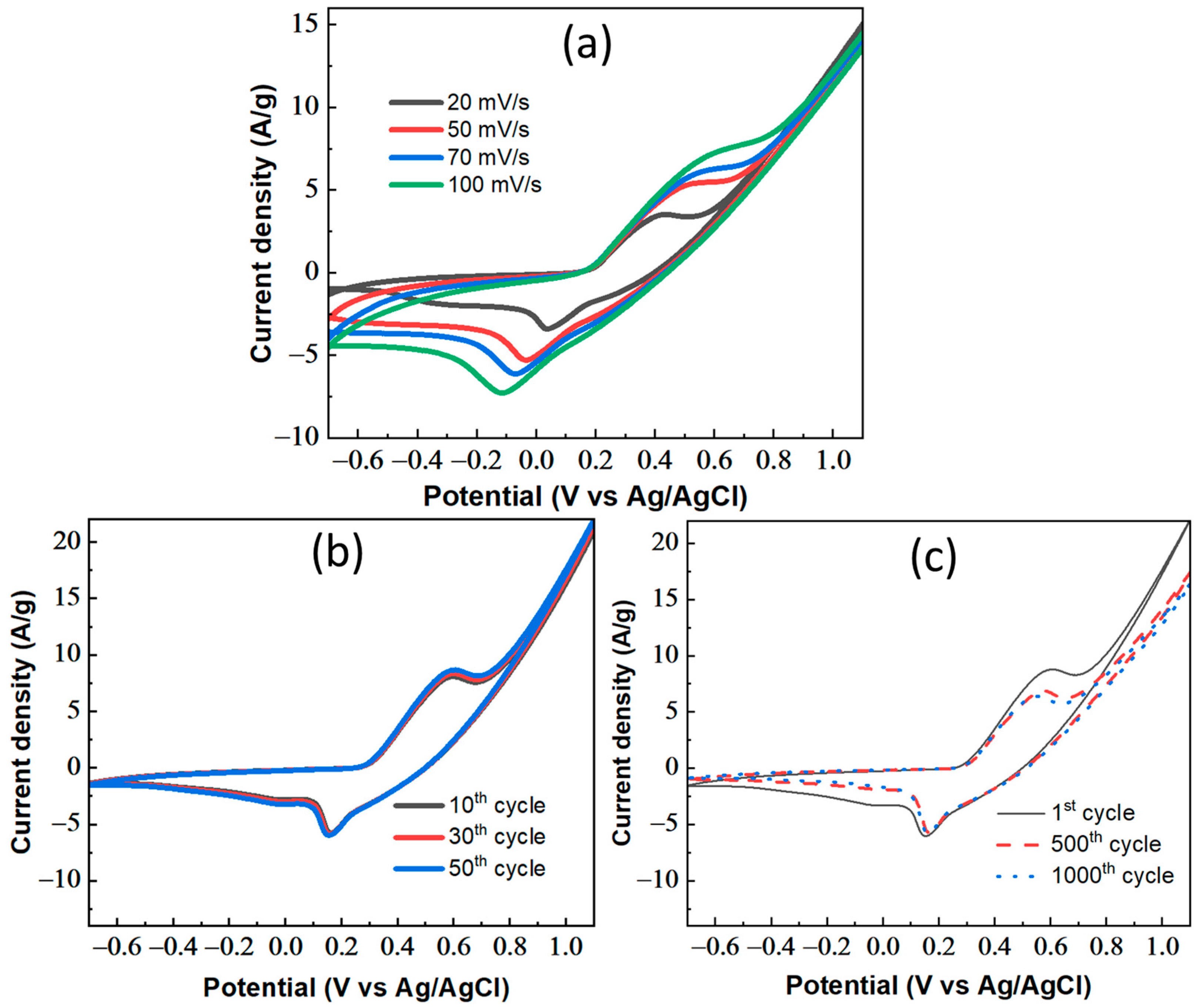
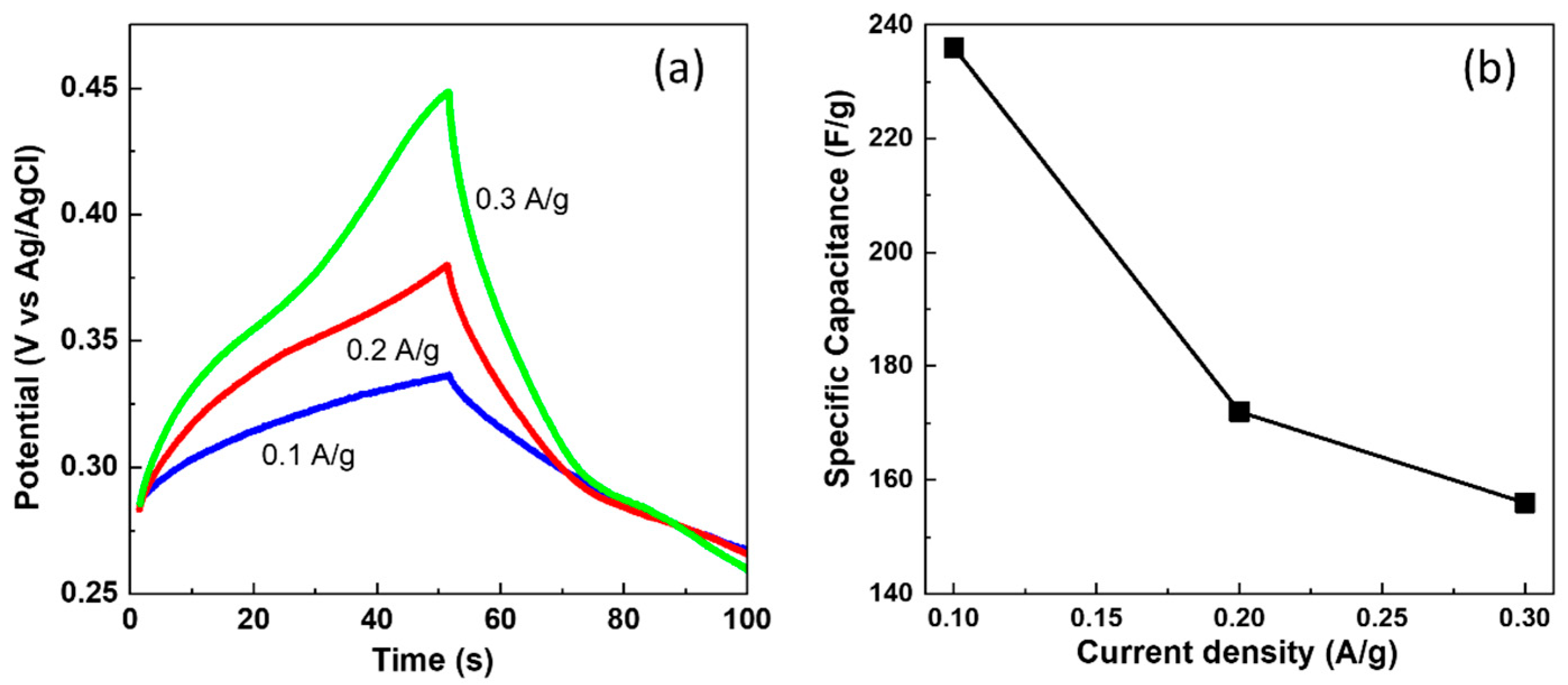
3.2. Electrochemical Measurement Results of CDPC Electrode

Electrochemical impedance spectroscopy (EIS) was conducted using the Autolab PSGTAT100 instrument with an oscillation frequency ranging from 100 kHz to 100 mHz.
The impedance characteristics of the CDPC electrode are illustrated in Figure 4b. The point of intersection with the real axis indicates the resistance between the electrode and the electrolyte. The semicircle present in the high-frequency region is attributed to the charge-transfer resistance, while the low-frequency line corresponds to the diffusion impedance of ions penetrating the electrode, commonly referred to as the Warburg impedance. The absence of a semicircle is notable. This discrepancy arises from the fact that the diameter of the semicircle in the high-frequency region of the impedance measurement is typically associated with the charge-transfer resistance. This shows that the CDPC electrode conducts electricity well with small charge-transfer resistance and an obvious irreversible semicircle [33].
The results of the measurements of the electrochemical properties of the material show that the energy storage capacity of the CDPC material is good and stable.
To rapidly evaluate the electrochemical properties of the CDPC electrode, the CV multi-cycle loop potential scanning method was used. The electrode after fabrication was CV-activated with a potential scanning speed of 20, 50, 70, and 100 mV/s and a potential scanning range from −0.7 to 1.1 V/SCE in a 6M KOH solution and then activated for 50 cycles until the CDPC electrode was stable, followed by activation for up to 1000 cycles with a scanning speed of 100 mV/S and potential scanning range from −0.7 to 1.1 V/SCE in a 6M KOH solution. The results of CV spectroscopy at different scanning speeds for the CDPC electrode are shown in Figure 5a.
Figure 5a shows that as the scan rate of the CV increases from 20 to 100 mV/s, the CV curves still maintain a symmetrical leaf-like shape, with no appearance of oxidation–reduction peak positions. This indicates that the CDPC electrode operates well and remains stable. As the potential scanning speed increases, the charge current density (positive value) and discharge density (negative value) gradually increase. This shows that the CDPC electrode is highly reversible. This also suggests that the reaction mechanism of the CDPC electrode follows the double-layer capacitance mechanism, similar to carbon-based materials from previous studies [22].
Similarly, after 10, 30, and 50 CV activation cycles, the charge current density (positive value) and discharge density (negative value) also gradually increase (Figure 5b). This shows that the CDPC electrode performs stably. This issue can be explained as, at the beginning of the reaction, the CDPC electrode needs some wetting time for the electrolyte solution to penetrate the CDPC structure and activate the reaction sites, as well as to remove any remaining impurities.
However, after 50 cycles of stable electrode activation with a CV, the charge current density and discharge current density at 500 and 1000 cycles both decreased. This shows that the electrode potential of the CDPC electrode decreases with the number of charge-discharge cycles (Figure 5c). With the CV of the CDPC electrode at cycles 1, 500, and 1000 with a scan rate of 100 mV/s (Figure 5c), software was used to help calculate the specific capacitance of the electrode. After the initial cycle, the specific capacitance registers at 6083 F/g. Subsequently, after 500 cycles, it decreases to 4736 F/g, and following 1000 cycles, it further reduces to 4548 F/g. The results show that the specific capacitance after 500 and 1000 CV was 77.85% and 74.7%, respectively, compared to the original electrode’s specific capacitance. However, from 500 to 1000 CV cycles, the specific capacitance of the electrode was reduced by only 2%. This shows that the CDPC electrode works stably and efficiently.
The CDPC electrode discharge was measured by applying a constant current with a change in current density of 0.1, 0.2, and 0.3 A/g for 120 s, with voltage in the range from 0.20 V to 0.45 V (Figure 6a,b).
As depicted in Figure 6a, the charge and discharge profiles manifest as symmetrical triangles, reflecting a high degree of symmetry. Notably, no discernible voltage drop occurs at elevated current densities, implying the material’s robust electrochemical characteristics even under substantial discharge currents. Here, energy storage within the electrode primarily occurs through the formation of charged double layers via physical adsorption. This observation is in consonance with the findings deduced from the CV curve analyses. Figure 6b further illustrates that at the lowest current density (0.1 A/g) and the highest current density (0.3 A/g), the specific capacitance of the carbon-derived material is measured at 236 F/g and 156 F/g, respectively. This finding indicates a decline in specific capacitance in response to increasing current density, thus providing insights into the material’s responsiveness to various current regimes.
Table 2 demonstrates that the specific capacitance values align well with previous studies under equivalent conditions regarding electrolyte composition and charge/discharge current density.

4. Conclusions

Coal-derived CDPC has been successfully fabricated via the modified Hummers method, using Vietnamese coal as the precursor. The fabricated nanomaterials have an average size of 3–10 nm and a porous nature. The existence of macropores and mesopores will not only assist electrolytes in penetrating the materials in full depth but also shorten the ion diffusion paths effectively. When being used as the anode electrode in a supercapacitor, the CDPC electrode exhibited excellent performance. Via EIS, Nyquist plots demonstrated the superior conductivity of the CDPC electrode, characterized by minimal charge-transfer resistance. This electrode showcased remarkable stability, retaining 74.7% of its capacitance after 1000 cycles. The constant current discharge method was used to determine that the specific capacitance of CDPC was 236 F/g at a current density of 0.1 A, exhibiting the expected reduction with increasing current density. The overall electrochemical evaluation underscores the commendable and stable energy storage capacity of the CDPC material. Overall, these findings collectively emphasize the potential of CDPC as a promising candidate for energy storage applications. This study demonstrates the potential of using Vietnamese coal to produce high-performance nanomaterials for energy storage applications. Further exploration and optimization of CDPC-based devices could promote advancements in energy storage technologies, as well as the development of new energy storage devices to meet the growing energy demand.

Author Contributions

Writing—original draft preparation, T.H.D. and V.T.N.; conceptualization, X.L.H.; software, V.T.N. and X.L.H.; data curation, T.N.N. and Q.D.N.; methodology, T.N.N. and T.K.N.T.; formal analysis, Q.D.N.; writing—review and editing, T.K.N.T. and T.H.D.; supervision, T.H.D. All authors have read and agreed to the published version of the manuscript.

Funding

This study was funded by the ministerial-level Science and Technology project, at the Ministry of Education and Training of Vietnam, budget 730,000,000 VND, code B2023-TNA-07.

Institutional Review Board Statement

Not applicable.

Informed Consent Statement

Not applicable.

Data Availability Statement

All the data are available within the manuscript.

Conflicts of Interest

The authors declare no conflicts of interest.

References

  1. Borchardt, L.; Zhu, Q.; Casco, M.E.; Berger, R.; Zhuang, X.; Kaskel, S.; Feng, X.; Xu, Q. Toward a molecular design of porous carbon materials. Mater. Today 2017, 20, 592–610. [Google Scholar] [CrossRef]
  2. Kang, B.T.; Ai, H.Q.; Lee, J.L. Single-atom vacancy induced changes in electronic and magnetic properties of graphyne. Carbon 2017, 116, 113–119. [Google Scholar] [CrossRef]
  3. Kumar, M.R.; Singh, S.; Fahmy, H.M.; Jaiswal, N.K.; Akin, S.; Shalan, A.E.; Mendez, S.L.; Salado, M. Next generation 2D materials for anodes in battery applications. J. Power Sources 2023, 5, 232256. [Google Scholar] [CrossRef]
  4. Sharma, R.; Kumar, H.; Kumar, G.; Sharma, S.; Aneja, R.; Sharma, A.K.; Kumar, R.; Kumar, P. Progress and challenges in electrochemical energy storage devices: Fabrication, electrode material, and economic aspects. Chem. Eng. J. 2023, 15, 143706. [Google Scholar] [CrossRef]
  5. Awasthi, K.; Srivastava, A.; Srivastava, O. Synthesis of carbon nanotubes. J. Nanosci. Nanotechnol. 2005, 5, 1616–1636. [Google Scholar] [CrossRef] [PubMed]
  6. Riya, T.; Balachandran, M. Luminescence and energy storage characteristics of coke-based graphite oxide. Mater. Chem. Phys. 2020, 257, 123854. [Google Scholar]
  7. Qin, Z.H. New advances in coal structure model. Int. J. Min. Sci. Technol. 2018, 28, 541–559. [Google Scholar] [CrossRef]
  8. Ma, X.M.; Dong, X.S.; Fan, Y.P. Prediction and characterization of the microcrystal structures of coal with molecular simulation. Energy Fuels 2018, 32, 3097–3107. [Google Scholar] [CrossRef]
  9. Mathews, J.P.; Chaffee, A.L. The molecular representations of coal—A review. Fuel 2012, 96, 1–14. [Google Scholar] [CrossRef]
  10. Vasireddy, S.; Morreale, B.; Cugini, A.; Song, C.; Spivey, J.J. Clean liquid fuels from direct coal liquefaction: Chemistry, catalysis, technological status and challenges. Energy Environ. Sci. 2011, 4, 311–345. [Google Scholar] [CrossRef]
  11. Haenel, M.W. Recent progress in coal structure research. Fuel 1992, 71, 1211–1223. [Google Scholar] [CrossRef]
  12. Thomas, R.; Manoj, B. Electrochemical Efficacies of Coal Derived Nanocarbons. Int. J. Coal Sci. Technol. 2021, 8, 459–472. [Google Scholar] [CrossRef]
  13. Xu, G.Z.; Yang, T.; Fang, Z.G.; Wang, Q.; Yang, C.; Zhao, X. Preparation and characterization of coal-based carbon foams by microwave heating process under ambient pressure. Diam. Relat. Mater. 2018, 86, 63–70. [Google Scholar] [CrossRef]
  14. Nilewski, L.; Mendoza, K.; Jalilov, A.S.; Berka, V.; Wu, G.; Sikkema, W.K.A.; Metzger, A.; Ye, R.; Zhang, R.; Luong, D.X.; et al. Highly oxidized graphene quantum dots from coal as efficient antioxidants. ACS Appl. Mater. Interfaces 2019, 11, 16815–16821. [Google Scholar] [CrossRef] [PubMed]
  15. Moothi, K.; Iyuke, S.E.; Meyyappan, M.; Falcon, R. Coal as a carbon source for carbon nanotube synthesis. Carbon 2012, 50, 2679–2690. [Google Scholar] [CrossRef]
  16. Zhou, Q.; Zhao, Z.; Zhang, Y.; Meng, B.; Zhou, A.; Qiu, J. Graphene Sheets from Graphitized Anthracite Coal: Preparation, Decoration, and Application. Energy Fuels 2012, 26, 5186–5192. [Google Scholar] [CrossRef]
  17. Ji, L.; Lin, Z.; Alcoutlabi, M.; Zhang, X. Recent Developments in Nanostructured Anode Materials for Rechargeable Lithium-Ion Batteries. Energy Environ. Sci. 2011, 4, 2682–2699. [Google Scholar] [CrossRef]
  18. Liu, Y.; Guo, X.; Tian, X.; Liu, Z. Coal-Based Semicoke-Derived Carbon Anode Materials with Tunable Microcrystalline Structure for Fast Lithium-Ion Storage. Nanomaterials 2022, 12, 4067. [Google Scholar] [CrossRef]
  19. Lee, S.E.; Kim, J.H.; Lee, Y.-S.; Bai, B.C.; Im, J.S. Effect of Crystallinity and Particle Size on Coke-Based Anode for Lithium Ion Batteries. Carbon Lett. 2021, 31, 911–920. [Google Scholar] [CrossRef]
  20. Fu, L.; Yang, L.; Shi, Y.; Wang, B.; Wu, Y. Synthesis of carbon coated nanoporous microcomposite and its rate capability for lithium ion battery. Microporous Mesoporous Mater. 2009, 117, 515–518. [Google Scholar] [CrossRef]
  21. Teo, E.Y.L.; Muniandy, L.; Ng, E.-P.; Adam, F.; Mohamed, A.R.; Jose, R.; Chong, K.F. High surface area activated carbon from rice husk as a high performance supercapacitor electrode. Electrochim. Acta 2016, 192, 110–119. [Google Scholar] [CrossRef]
  22. Guo, Y.; Qi, J.; Jiang, Y.; Yang, S.; Wang, Z.; Xu, H. Performance of electrical double layer capacitors with porous carbons derived from rice husk. Mater. Chem. Phys. 2003, 80, 704–7030. [Google Scholar] [CrossRef]
  23. Guo, Y.; Zhao, J.; Zhang, H.; Yang, S.; Qi, J.; Wang, Z.; Xu, H. Use of rice husk-based porous carbon for adsorption of Rhodamine B from aqueous solutions. Dye. Pigment. 2005, 66, 123–128. [Google Scholar] [CrossRef]
  24. Vinayagam, M.; Babu, R.S.; Sivasamy, A.; de Barros, A.L.F. Biomass-derived porous activated carbon nanofibers from Sapindus trifoliatus nut shells for high-performance symmetric supercapacitor applications. Carbon Lett. 2021, 31, 1133–1143. [Google Scholar] [CrossRef]
  25. Vinayagam, M.; Babu, R.S.; Sivasamy, A.; de Barros, A.L.F. Biomass-derived porous activated carbon from Syzygium cumini fruit shells and Chrysopogon zizanioides roots for high-energy density symmetric supercapacitors. Biomass Bioenergy 2020, 143, 105838. [Google Scholar] [CrossRef]
  26. Zhang, Q.; Wang, W.; Jiang, D.; Huang, X. Mesoporous activated carbon decorated with MnO as anode materials for lithium ion batteries. J. Mater. Sci. 2015, 51, 3536–3544. [Google Scholar] [CrossRef]
  27. Yang, N.; Zhu, S.; Zhang, D.; Xu, S. Synthesis and properties of magnetic Fe3O4-activated carbon nanocomposite particles for dye removal. Mater. Lett. 2008, 62, 645–647. [Google Scholar] [CrossRef]
  28. Hao, M.; Xiao, N.; Wang, Y.; Li, H.; Zhou, Y.; Liu, C.; Qiu, J. Pitch-derived N-doped porous carbon nanosheets with expanded interlayer distance as high-performance sodium-ion battery. Fuel Process. Technol. 2018, 177, 328–333. [Google Scholar] [CrossRef]
  29. Zhao, X.J.; Jia, W.; Wu, X.Y.; Lv, Y.; Qiu, J.; Guo, J.; Wang, X.; Jia, D.; Yan, J.; Wu, D. Ultrafine MoO3 anchored in coal-based carbon nanofibers as anode for advanced lithium-ion batteries. Carbon 2020, 156, 445–452. [Google Scholar] [CrossRef]
  30. Chen, L.; Zhang, Y.; Lin, C.; Yang, W.; Meng, Y.; Guo, Y.; Li, M.; Xiao, D. Hierarchically porous nitrogen-rich carbon derived from wheat straw as an ultra-high-rate anode for lithium ion batteries. J. Mater. Chem. A 2014, 2, 9684–9690. [Google Scholar] [CrossRef]
  31. Linghu, R.; Liu, Y.; Zhang, Y.; Zhang, Y.; Gao, J.; Zhong, Y. Characterization of Delayed Coke and Fluid Coke Gasification Using Blast Furnace Slag as a Disposable Catalyst. Energy Fuels 2019, 33, 6734–6741. [Google Scholar] [CrossRef]
  32. Krishnamoorthy, K.; Veerapandian, M.; Yun, K.; Kim, S.-J. The Chemical and Structural Analysis of Graphene Oxide with Different Degrees of Oxidation. Carbon 2013, 53, 38–49. [Google Scholar] [CrossRef]
  33. Le, T.H.; Ngo, V.H.; Nguyen, M.T.; Nguyen, V.C.; Vu, D.N.; Pham, T.D.; Tran, D.T. Enhanced Electrochemical Performance of Porous Carbon Derived from Cornstalks for Supercapacitor Applications. J. Electron. Mater. 2021, 50, 6854–6861. [Google Scholar] [CrossRef]
  34. Liu, T.; Wang, K.; Chen, Y.; Zhao, S.; Han, Y. Dominant Role of Wettability in Improving the Specific Capacitance. Green Energy Environ. 2019, 4, 171–179. [Google Scholar] [CrossRef]
  35. Xiao, H.; Yao, S.; Liu, H.; Qu, F.; Zhang, X.; Wu, X. NiO Nanosheet Assembles for Supercapacitor Electrode Materials. Prog. Nat. Sci. Mater. Int. 2016, 26, 271–275. [Google Scholar] [CrossRef]
  36. Zhang, J.; Gong, L.; Sun, K.; Jiang, J.; Zhang, X. Preparation of Activated Carbon from Waste Camellia Oleifera Shell for Supercapacitor Application. J. Solid State Electrochem. 2012, 16, 2179–2186. [Google Scholar] [CrossRef]
  37. Ali, G.A.M.; Manaf, S.A.B.A.; Kumar, A.; Chong, K.F.; Hegde, G. High Performance Supercapacitor Using Catalysis Free Porous Carbon Nanoparticles. J. Phys. D Appl. Phys. 2014, 47, 495307. [Google Scholar] [CrossRef]
  38. Wang, H.; Wang, M.; Tang, Y. A Novel Zinc-Ion Hybrid Supercapacitor for Long-Life and Low-Cost Energy Storage Applications. Energy Storage Mater. 2018, 13, 1–7. [Google Scholar] [CrossRef]
  39. Wang, K.; Li, L.; Zhang, T.; Liu, Z. Nitrogen-Doped Graphene for Supercapacitor with Long-Term Electrochemical Stability. Energy 2014, 70, 612–617. [Google Scholar] [CrossRef]
  40. Gao, F.; Qu, J.Y.; Zhao, Z.B.; Quan, Z.; Beibei, L.; Jieshan, Q. A green strategy for the synthesis of graphene supported Mn3O4 nanocomposites from graphitized coal and their supercapacitor application. Carbon 2014, 80, 640–650. [Google Scholar] [CrossRef]
  41. Qiu, J.S.; Li, Y.F.; Wang, Y.P.; Wang, T.; Zhao, Z.; Zhou, Y.; Li, F.; Cheng, H. High-purity single-wall carbon nanotubes synthesized from coal by arc discharge. Carbon 2003, 41, 2159–2217. [Google Scholar] [CrossRef]
Figure 1. (a) Preparation of electrode fabrication tools; (b) electrode fabricated using pressing equipment; (c) formed electrode with black color.
Applsci 14 00965 g001
Figure 2. Thermogravimetric (TG—black) and differential thermal analysis (DTA—red) of CP.
Applsci 14 00965 g002
Figure 3. (a,b) SEM images of CP and CDPC; (c) EDX spectrum of CDPC; (d) XRD pattern of CP (black) and CDPC (red); (e) Raman spectra of CP (black) and CDPC (red); (f) TEM of CDPC with low resolution and (g) with high resolution.
Applsci 14 00965 g003
Figure 4. (a) Nitrogen adsorption–desorption isotherms of CP and CDPC; (b) CDPC electrode impedance.
Applsci 14 00965 g004
Figure 5. (a) CV of CDPC electrode with different scanning rates (20–100 mV/S); (b) CV of CDPC after 10, 30, and 50 cycles and 100 mV/s scan rate; and (c) CV of CDPC after 1, 500, and 1000 cycles and 100 mV/s scan rate.
Applsci 14 00965 g005
Figure 6. (a) Galvanostatic charge–discharge curve of CDPC electrode in 6 M KOH at different current densities (0.1, 0.2, and 0.3 A/g) and (b) specific capacitance of CDPC plotted against current density.
Applsci 14 00965 g006
Table 1. EDX analysis results of CDPC.
Element % Mass% Atom
C80.8885.53
O17.1813.64
Al0.410.19
Si0.870.39
S0.510.20
Mn 0.15003
Total100.00100.00
Table 2. Comparing specific capacitance with prior studies.
MaterialsElectrolyteCharge/Discharge Current Density (A/g)Specific Capacitance (F/g)Reference
Nanoporous gold[EMIM]BF40.1479.1[34]
NiO nanosheet assembles3 M KOH0.581.67[35]
Active carbon (COS)1 M H2SO4
6 M KOH
0.2
0.2
374
266
[36]
Porous carbon nanoparticles (PCNs)6 M KOH0.06309[37]
Zn-HSC1M Zn(CF3SO3)20.1170[38]
Nitrogen-doped graphene6 M KOH0.5
5
197
151
[39]
Graphene nanocapsules (from coal tar pitch using a nano-ZnO-template strategy coupled with in situ KOH activation) (GNCs)6 M KOH0.05277[40]
Coal-derived porous
carbon fibers (CPCFs)
6 M KOH1170[41]
CDPC6 M KOH0.1
0.3
236
156
This work
Disclaimer/Publisher’s Note: The statements, opinions and data contained in all publications are solely those of the individual author(s) and contributor(s) and not of MDPI and/or the editor(s). MDPI and/or the editor(s) disclaim responsibility for any injury to people or property resulting from any ideas, methods, instructions or products referred to in the content.

