1. Introduction
The application of artificial intelligence (AI) elements has become the most common trend in modern electric drives. This is mainly due to the requirements of Industry 5.0, which often promotes the autonomous, robust, and adaptive operation of machines and robots. This machinery should be able to reproduce the desired dynamics without the intervention of a dedicated operator. The machinery’s operation in various conditions is the most important and inextricable requirement. Different ideas have provided solutions to this issue, each having advantages and disadvantages. Neural network controllers [
1,
2,
3] are commonly described in the literature; however, the most notable disadvantage is the necessity for the parallel computing of the neurons in a single layer. This leads to more powerful hardware and, therefore, cost increases. On the other hand, there are standard PI controllers or state controllers enhanced by tunable parameters. This adaptation can be achieved with different algorithms, leading to varied complexity and efficiency. A common problem of such controllers is the stability issue [
4,
5,
6].
Modern industry is a meaningful concept whose main role is to ensure the sustainable development of the economy and the dynamic growth of the quality of people’s lives. In almost every single factory there are plenty of essential devices that use electric drives. Coal mines, heavy elevators, HVAC control systems, small tools, printers, and CNC machines all use electric drives. A strong desire to generate high-quality products has forced factories to become more productive. The key to ensuring a reasonable production rate is to minimize the risk of breakdowns or outages caused by electric drive systems. One of the biggest weaknesses of conventional brushed DC motors is their maintenance. Because of the friction caused by brushes, classic DC motors require the periodic exchange of certain components [
7,
8]. Comparing both constructions, it is unquestionable that the brushless DC (BLDC) motor has a simplified internal structure. Furthermore, the lower number of internal elements in the BLDC motor allows manufacturers to design a motor with a smaller chassis than its conventional equivalent with the same power. This has a huge influence on decreasing the electromagnetic noise generated by the motor. From another point of view, the construction of the BLDC motor is a critical feature that ensures much better dynamics and a higher efficiency compared to brushed motors, with improvements of up to 95%. Because of this, it is obvious that BLDC motors provide the user with an opportunity to control their speed and position at a precise level. This makes these machines a perfect choice as the main drive in popular applications (e.g., CNC machines or robots) [
9,
10]. The biggest and most noticeable disadvantage of brushless motors is the necessity of using a dedicated controller to ensure correct operation.
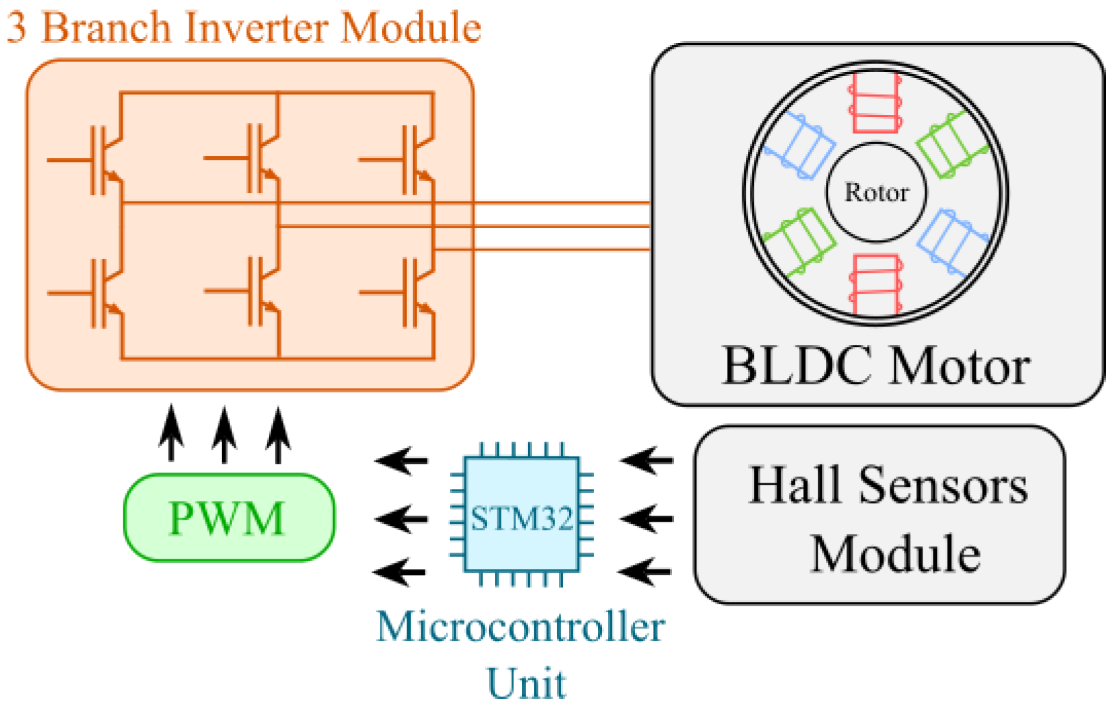
Nowadays, brushless electric motors can be distinguished as one of the most important parts of electric drives and can be divided into permanent-magnet synchronous motors (PMSMs) and BLDC motors. In spite of their similar mechanical constructions (stator windings and permanent magnets placed on the rotor), a huge difference between them can be noticed while developing a proper control system. Due to the fact that the BLDC motor works with a direct current, the shape of the back electromotive force is trapezoidal. Because of this, a different technique of control is required. The most essential element of a typical drive with a three-phase BLDC motor is a power electronic controller—a three-branch inverter module, with two switches in each branch [
11,
12]. The internal structure of a typical drive with a BLDC motor is shown in
Figure 1.
The goal is to make the BLDC motor rotate properly in both directions. For this purpose, a particular inverter is used. It is a substitute for the mechanical commutator used in brushed DC motors. The electronic commutator works with no physical connection between the stator and rotor (a lack of brushes). In order to make the motor rotate properly, information about the current rotor position needs to be given to the microcontroller unit. In modern BLDC motor controllers, this is usually realized by receiving information from Hall sensors located inside the motor. More advanced devices are based on the fact that in a specific time period the current flows only through two of three phases. Therefore, it is possible to deduce a current rotor position based on calculating the back electromotive force induced on the unused phase [
13,
14]. Having received the rotor position, it is compared by a microcontroller with the implemented switching tables. These are used to define which of the six transistor switches need to be open or closed (based on the current rotor position) in a specific time window to make the motor rotate in the desired direction. There are many types of BLDC motor controllers available on the market. This allows the user to choose an appropriate controller for the project to be performed. No matter what kind of project is being realized, one can find a proper controller for its requirements, e.g., a Radio-Controlled (RC) model, electric scooter, automotive industry application, or large control cabinet for a high-power BLDC motor [
15,
16,
17,
18,
19]. Moreover, the constant improvement of microcontrollers ensures that a variety of hardware solutions are available on the market. Depending on the designed application and initial requirements of the project, it is possible to choose between both amateur and professional microprocessors. Even a simple programable device, due to its computational capabilities, can provide enough power to handle the BLDC commutation process [
20,
21]. Furthermore, modern Advanced RISC Machine (ARM) processors ensure a perfect combination of computational capabilities while fulfilling the assumption of a low-cost solution. These devices are capable of running even complicated algorithms while handling the BLDC commutation process simultaneously [
22,
23]. Due to the constantly increasing interest in ARM processors, manufacturers offer BLDC motor controllers in the form of dedicated shields [
24]. Additionally, demanding applications are often handled by modern digital signal processors, which are a convenient way to run a variety of advanced algorithms [
25,
26,
27]. The most sophisticated implementations (e.g., BLDC neural speed controllers) are often executed with the use of parallel computing ensured by field-programable gate array (FPGA) modules [
28,
29,
30]. However, in terms of testing and developing rapid-prototyping systems, FPGAs are widely used as well [
31].
Despite the fact that classic control structures (e.g., PID) are incredibly popular methods in modern industry, it is well known that they are not convenient in the context of nonlinear systems. Moreover, the values of the object parameters can fluctuate over time. Using conventional techniques, the precision of control is difficult to ensure. This is the point at which fuzzy logic becomes a reasonable solution. It is by definition a branch of mathematics that was designed for describing uncertain objects. The main goal while creating fuzzy logic principles is to obtain a tool capable of modeling nonlinear phenomena, which are usually hard to describe with mathematical equations. One of the most important parts of data processing in a fuzzy model is the rule base—defined using the designer’s experience and knowledge. Considering the fact that, nowadays, fuzzy logic may be used in many fields, it is also widely implemented in control systems, in the form of a fuzzy logic controller [
32,
33,
34,
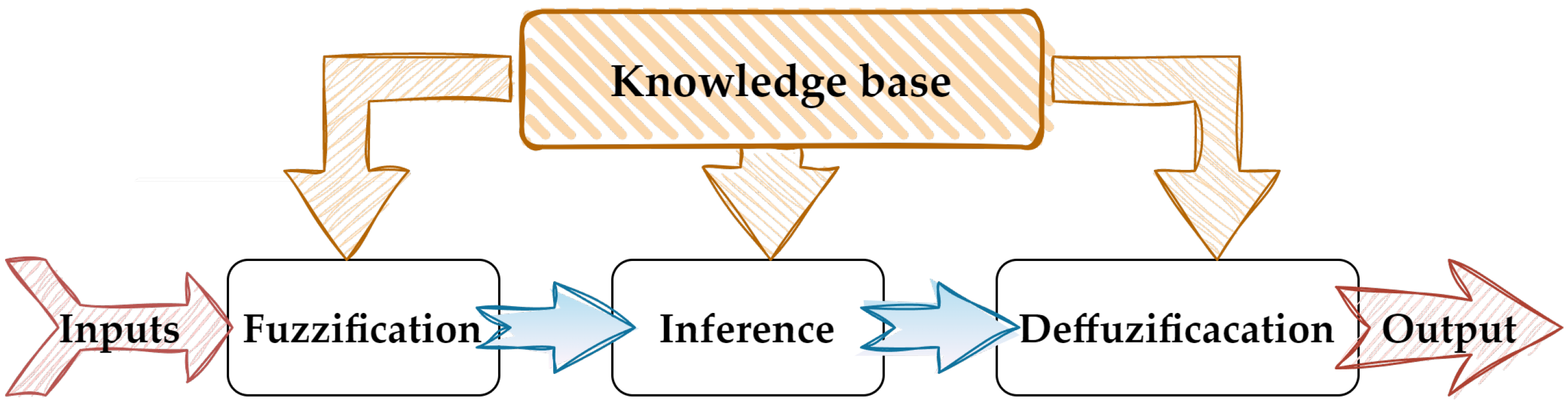
35]. The main idea of these controllers is to create a dependency between the input signals and the output of the controller using predefined rules. Thus, it is possible to describe the current state of a plant with linguistic variables (instead of specific state equations). This can be performed after the fuzzification stage in the first layer of the controller. The second layer (inference) calculates conclusions and their significance in the final control signal through several iterations of the algorithm. Then, the received values are taken to the defuzzification layer and changed from the fuzzy variable to a specific value, which allows the fuzzy model to cooperate with the rest of the control system (e.g., the torque control loop of the electric drive) [
34,
35,
36,
37,
38]. Additionally, the dynamic development of cheap and powerful microprocessor units makes it easier and more reasonable to use fuzzy logic controllers in everyday applications. One of the most representative implementations, based on a fuzzy logic model, may be seen in a typical modern car, i.e., an active cruise control system [
39]. Considering the fact that there are a variety of reference speed values that can be achieved by a car, the characteristics of the plant are strongly dependent on the current gear, actual motor speed value, and weight of the vehicle. There are also plenty of factors and circumstances that directly influence the above-mentioned characteristics (e.g., the number of people inside the car). Therefore, it is clear that a conventional controller (PID/PI) may be insufficient. Moreover, a fuzzy logic controller does not require specific plant parameters (during the design stage) to make the system work properly.
Any control structure requires the tuning of its parameters to perform well with different objects. The efficiency and performance of the controlled drive rely on correctly selected coefficients. A variety of optimization approaches can be found in control theory, among which standard (based on a mathematical model of the structure) and numerical methods can be distinguished. One of the most interesting methods, which seems to have become very popular in recent years, is based on metaheuristic algorithms. These describe different calculations that provide general instructions to minimize the value of a given cost function. In comparison to standard optimization algorithms, metaheuristic optimizers work without difficult mathematical calculations (e.g., the gradient can be neglected) [
40]. Thus, they can be applied easily to complex problems (including nonlinear objects and parameter modifications). The implementation of the tool is universal for different issues (without additional recalculations). Due to these advantages, a wide range of applications in different areas of science [
41], engineering [
42,
43], economics [
44], and medicine [
45] can be found. Their high popularity is a result of not only the ease of application but also the high efficiency of metaheuristic algorithms. Because of the iterative process, the initial results may be quickly modified, and then, in the following iterations, their precision may be improved. Metaheuristic algorithms are often based on observations of nature, especially swarm processes [
46]. These methods often include elements of artificial intelligence (AI) [
47].
This article describes the complete design process and implementation of a fuzzy logic speed controller for a BLDC motor. The theoretical background and mathematical model of the control system are analyzed. Then, the stability issue is considered, and a practical application of the Lyapunov theorem for rule base definition is provided. The next part presents an application of a nature-inspired metaheuristic optimizer for controller efficiency improvement (Chameleon Swarm Algorithm). The subsequent section introduces the results of simulation tests of the established fuzzy logic control structure. Considerations of different operation scenarios are discussed, and the chosen speed transients are presented. A significant part of the paper is related to the design process and construction of the microcontroller system and power electronics for a low-cost test bench. The hardware section deals with the electronics of the device and ancillary mechanical equipment (cabinets, coupling). The developed control software (graphical user interface) is also briefly analyzed. The paper ends with experimental results and concluding remarks.
3. Simulation Results
The main point of this research was the hardware implementation of a controller in a low-cost microcontroller board. In order to reduce the risk of faults in the control algorithm and (potential) hardware damage, the implementation was preceded by simulation tests. The model was established in Matlab/Simulink 2022b on the basis of the mathematical description given in the introductory part of the paper (
Section 2). Because further hardware development was the main objective, the reference and measured speeds were subjected to interference from the noise signal in order to align the test conditions with a real microcontroller system environment. The time constants for the transfer functions representing the power electronics
and mechanical inertia
of the laboratory drive and the simulation sample time
are presented in
Table 3.
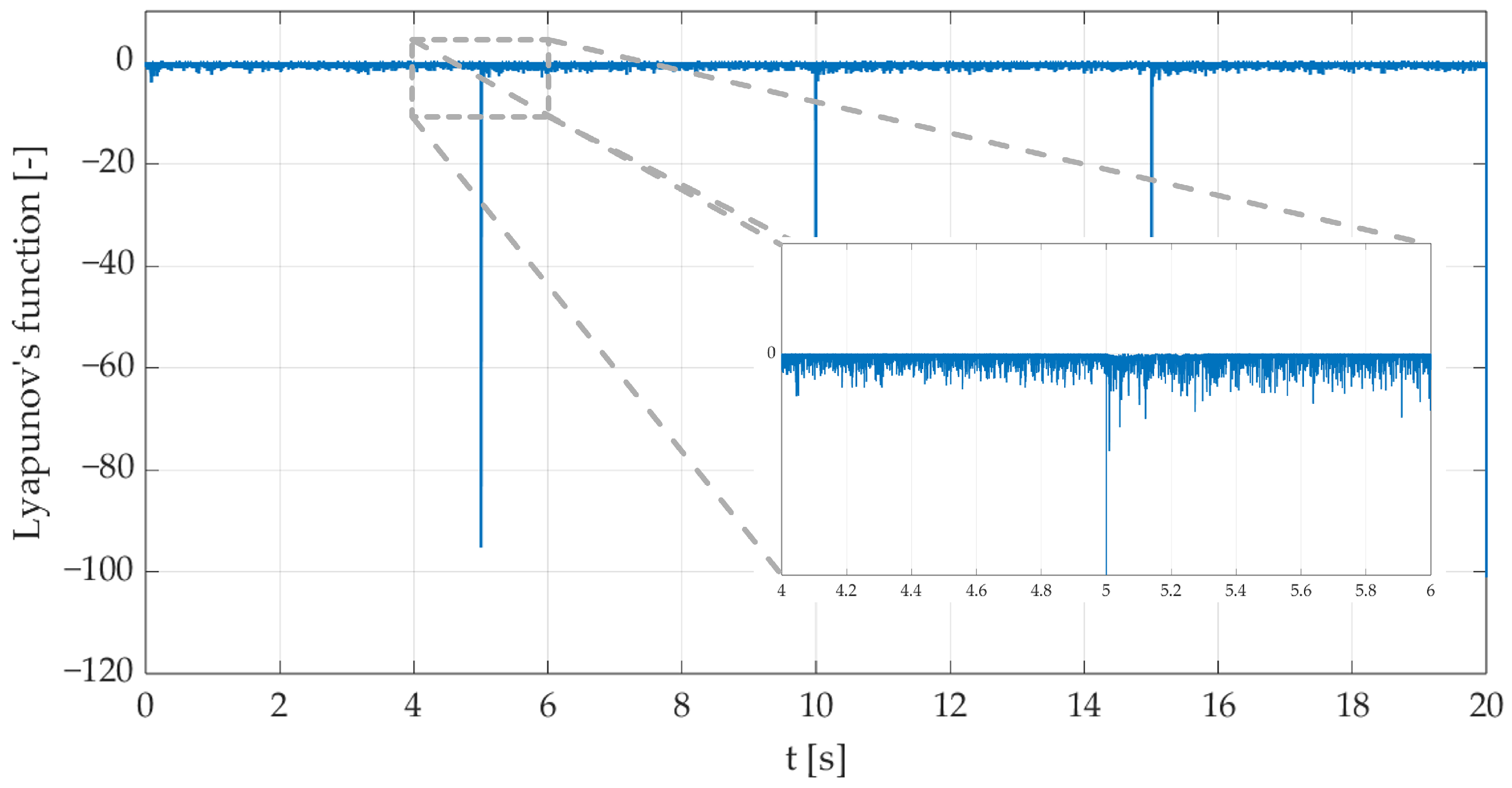
The first test was conducted with controller gains equal to 1 to appraise the accuracy of the defined rules. Despite the fact that the speed transient dynamics were not at a satisfactory level, the test was passed correctly. The Lyapunov function
was within the desired range throughout the whole test, as we can see in
Figure 8. For the test purposes, a square reference signal was used, representing the most difficult operation conditions—immediate response to reference speed change.
The controller gains were then optimized using the CSA with all the above considerations taken into account. For the purpose of the research, a simple cost function was defined (
26):
where
S is the number of considered samples;
is the measured speed; and
is the reference speed.
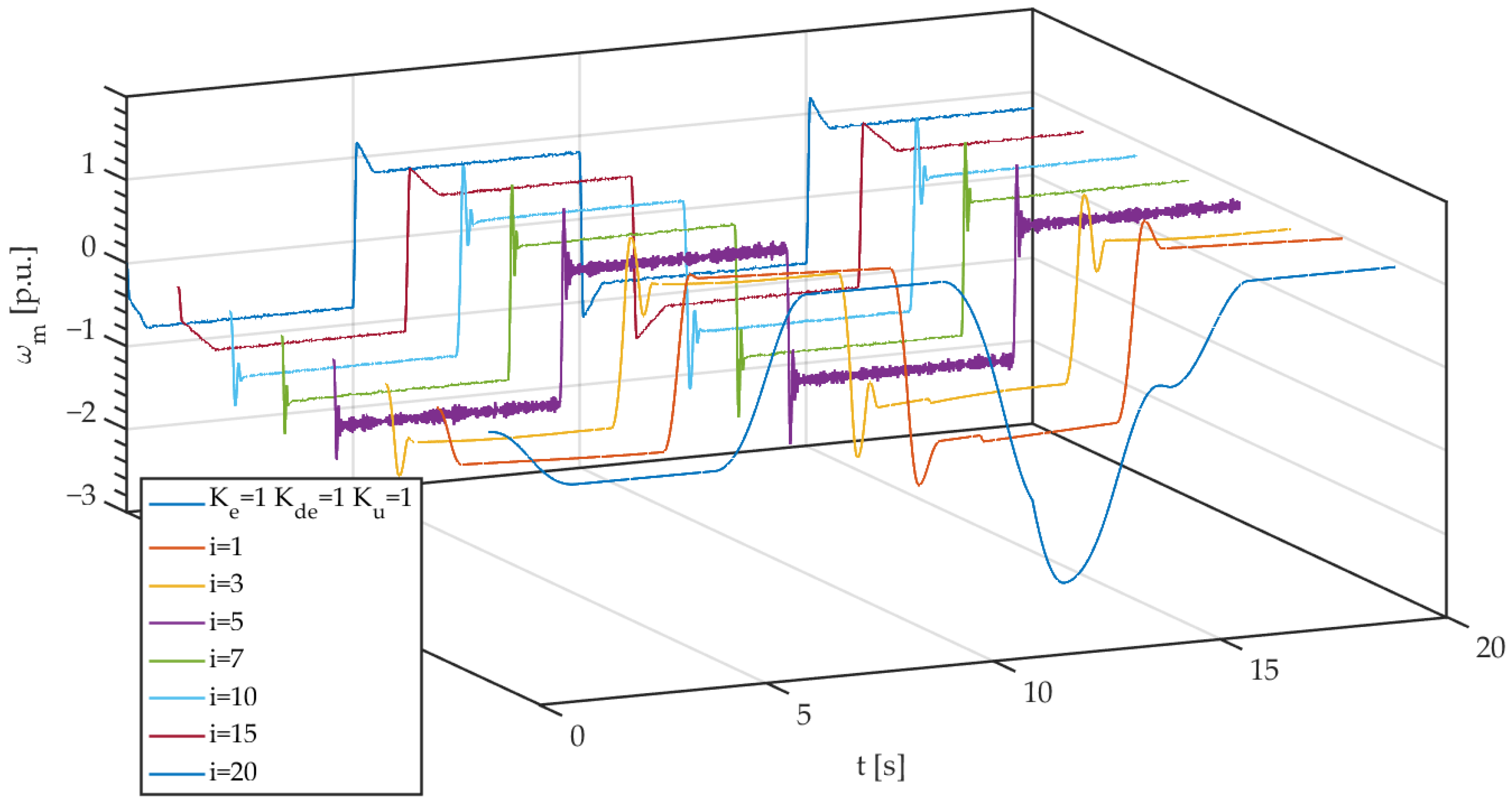
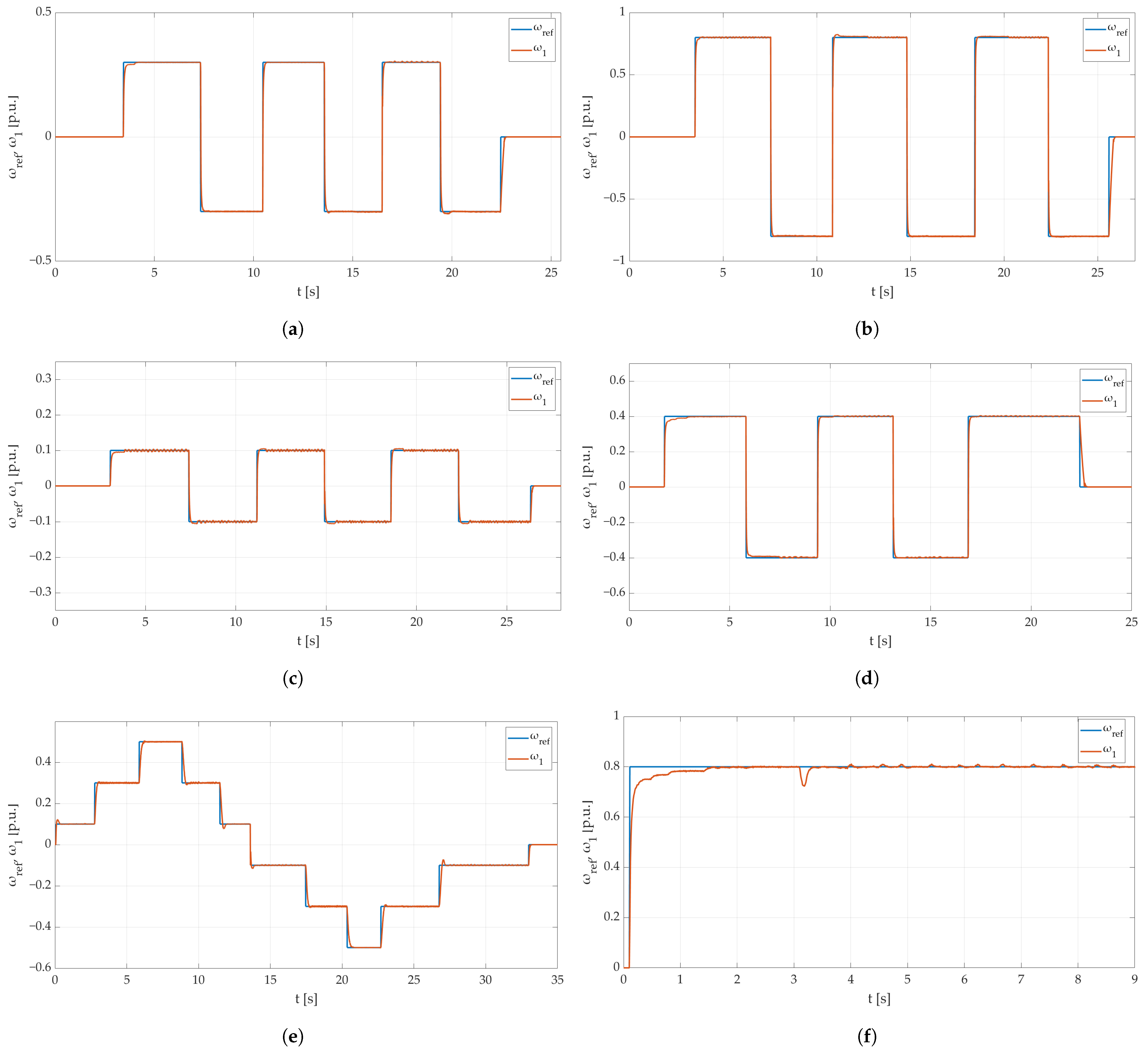
In
Figure 9, the chosen speed transients obtained in the selected iterations (
i) of the CSA optimization are depicted. For comparison purposes, the speed of the motor drive measured for the case of the controller with gains equal to 1 is also attached.
An unquestionable improvement in the dynamics can be noticed in
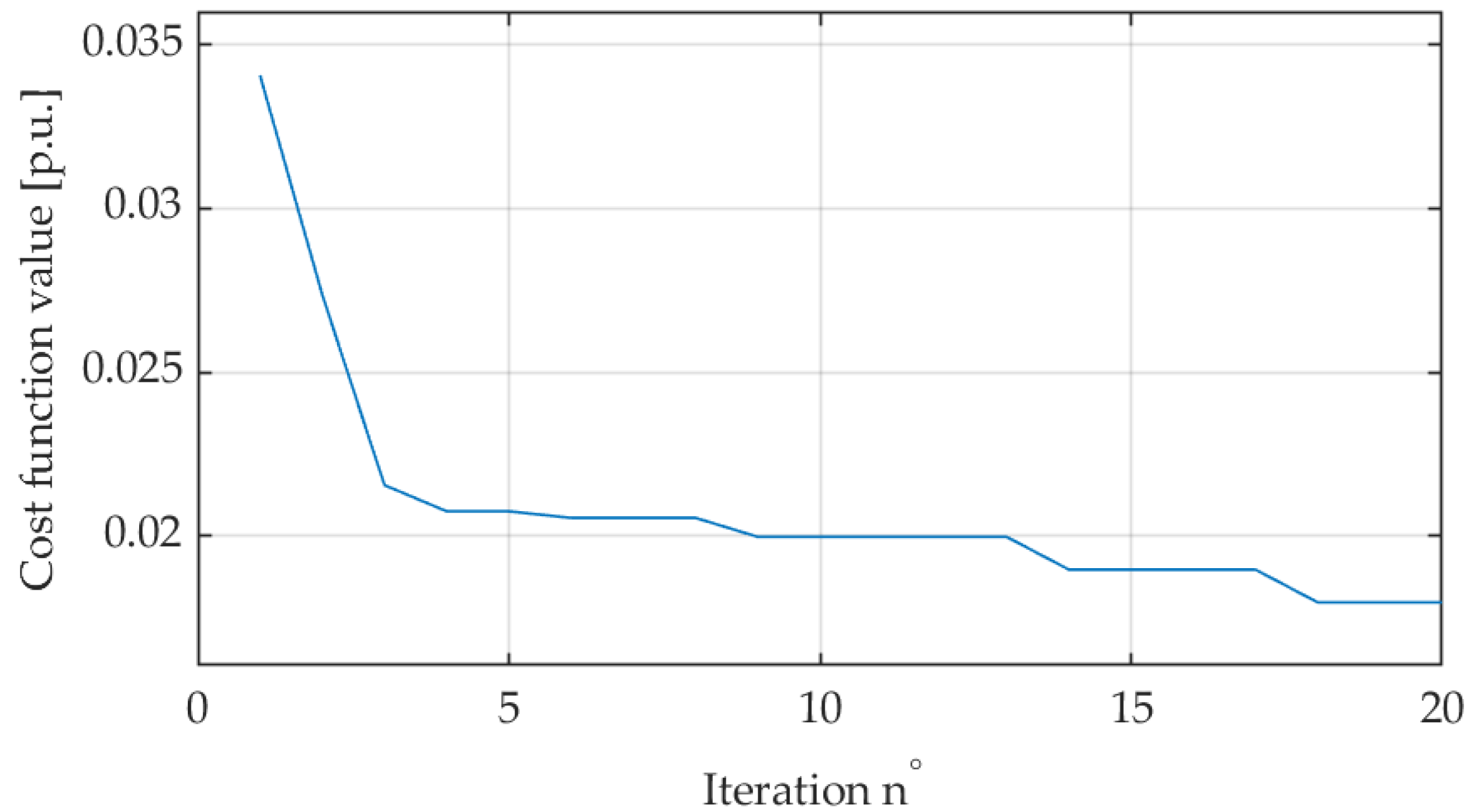
Figure 9. The overshoots and oscillations in both the dynamic and static operation of the motor were reduced drastically. This figure also confirms the fact that the correct tuning of the controller gains is essential for correct operation. It should be emphasized that the fuzzy logic controller, even in a very basic configuration, provides the possibility to track the reference signal. However, the dynamics can be improved by correct gains calculations. The presented transients also confirm that the CSA is an efficient tool for tuning fuzzy controllers. After five iterations of the algorithm processing, the offset in the steady state was eliminated. The further iterations eliminated the overshoot level and damped high-frequency oscillations. Thus, the error between the reference signal and the measured speed was minimized—this can be noticed in
Figure 10.
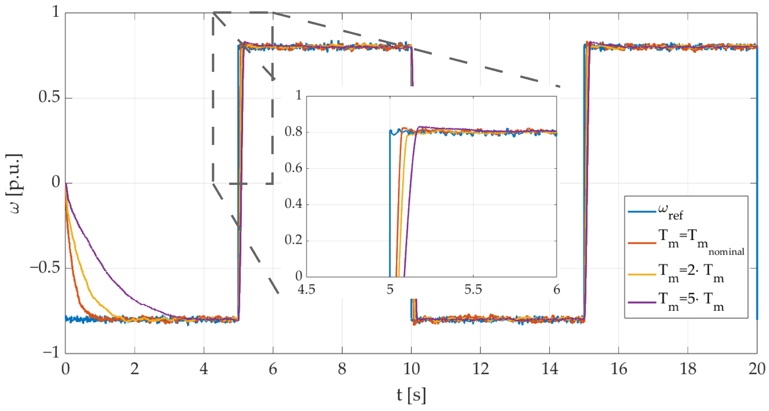
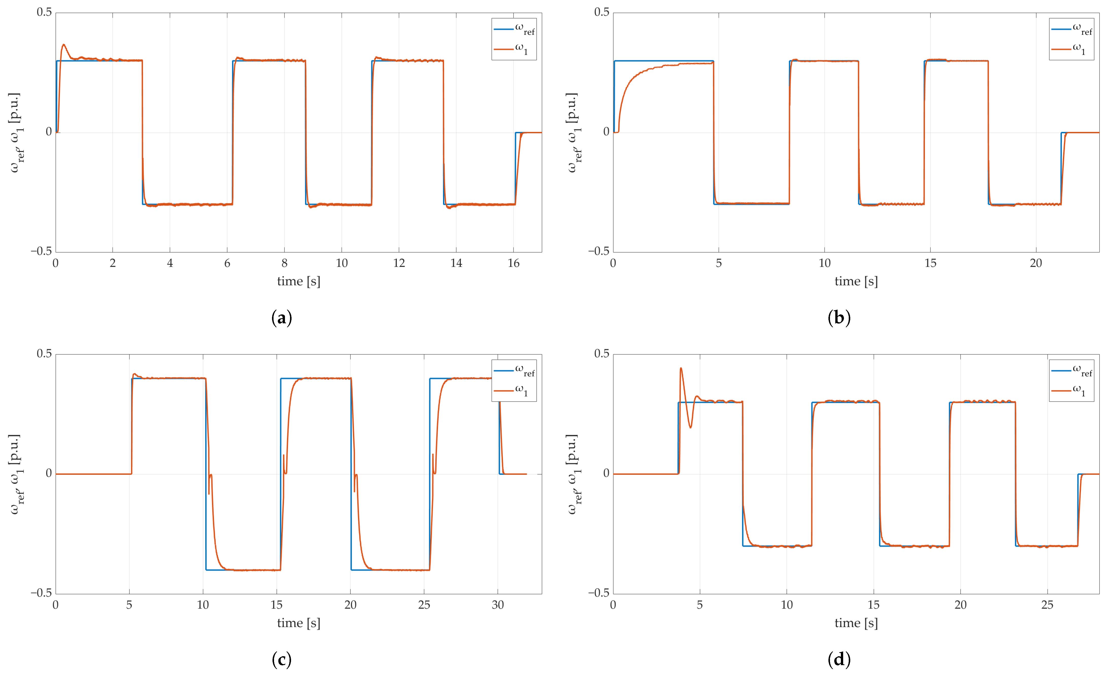
The parameters of motors in an industrial environment change during operation because of the variable temperature, different load torques, etc. [
79]. The second part of the simulation tests was focused on the verification of the drive operation with an increased mechanical time constant
.
Figure 11 presents the speed transients of the motor with different (disturbed) time constants and an initially tuned controller. The results were obtained for the following optimized controller coefficients:
,
, and
It can be seen that all the transients tracked the reference signals with high precision. However, the increase in the time constant, as was expected, led to an increased rise time for the speed.
5. Conclusions
This paper focused on two main points: the design process of a fuzzy speed controller applied to an electric drive with a BLDC motor, and the hardware construction proposed and used for the experimental tests.
The designed fuzzy rules base was defined according to the Lyapunov stability criterion. The candidate function was fitted to the presented problem and derived in order to generate the stability condition. A successful approach to controller tuning with a metaheuristic optimization algorithm was also presented. For this purpose, the Chameleon Swarm Algorithm was used. The combination of the above-mentioned methods was a novel solution for problematic issues related to the fuzzy controller design process. It led to the efficient application of this algorithm, known from artificial intelligence, to an electric drive.
The whole hardware controller deployment process turned out to be complex in some areas. One of the greatest difficulties faced during hardware controller development was related to software integration issues. The deployment process showed that having all devices send and receive the necessary commands in a particular time window is crucial for making the whole system work properly and may be a huge concern.
The main feature observed in the tests was the robustness of the fuzzy controller against parametric disturbance. A modified mechanical time constant did not significantly affect the speed transients. The achieved results confirmed the precise operation of the drive according to the reference waveform.
The successful accomplishment of the described project constitutes a promising base for future work. One of the possible avenues of future work is rebuilding the whole device using SMD components and independent microcontroller units placed on a single PCB board. In this way, it would be possible to reduce the size of the assembled device. The developed hardware may also be used as an alternative device for testing different control algorithms, as it may be a competitive solution compared to, e.g., the popular dSPACE system, commonly used in the field of electric drives.


