Article

Optimized Water Distillation Layout for Detritiation Purpose

Fusion and Technology for Nuclear Safety and Security Department, ENEA, Via E. Fermi 45, 00044 Frascati, RM, Italy
*
Author to whom correspondence should be addressed.
Appl. Sci. 2024, 14(4), 1328; https://doi.org/10.3390/app14041328
Submission received: 16 January 2024 / Revised: 31 January 2024 / Accepted: 4 February 2024 / Published: 6 February 2024
(This article belongs to the Special Issue Advances in Fusion Engineering and Design Volume II)

Abstract

:
Tritium permeation constitutes a key issue for the future EU-DEMO, especially in the Breeding Blanket (BB) where fusion energy must be delivered to the Primary Heat Transport System (PHTS) and where tritium must be bred. Currently, the mitigation strategy of the tritium permeation from BB into primary coolant is based on the adoption of anti-permeation barriers and on the operation of the Coolant Purification System (CPS). This system must ensure a tritium removal rate from the primary coolant equal to the BB permeation rate at a target tritium-specific activity inside the PHTS. In the case of the Water-Cooled Lithium Lead (WCLL) BB, water distillation was selected as the most promising technology for the primary coolant detritiation due to its intrinsic simplicity and safety. Nevertheless, power consumption was recognized as a relevant concern. For this reason, the present work aims at investigating possibilities to reduce power consumption of the water CPS implementing Heat Pump-Assisted Distillation (HPAD) concepts. To do this, a review of the HPADs developed in the chemical industry was carried out, and the best options for the water CPS were identified based on qualitative considerations. Then, a quantitatively assessment of the best solution in terms of power consumption and tritium inventory was performed with the commercial numerical tool Aspen Plus. Finally, the Mechanical Vapor Recompression (MVR) concept was recognized as the most promising solution, ensuring a power saving of around 80% while keeping a limited tritium inventory.

1. Introduction

The Breeding Blanket (BB) represents the step forward from ITER to a Fusion Power Plant (FPP), being the most important and novel components. Its central role in the development of a FPP is demonstrated by the great attention posed by the European fusion community (e.g., the EUROfusion consortium) on the testing and qualification strategy for the EU-DEMO BB [1]. The essential functionalities of a FPP BB can be summarized as (i) the need to absorb the largest part of the fusion energy transported by neutrons and delivers it to the Primary Heat Transport System (PHTS), (ii) the ability to breed enough tritium for self-sufficiency of the machine, and (iii) the contribution, along with the vacuum vessel, to the shielding of various components from nuclear radiation.
As such, the BB must ensure an efficient heat transfer toward the PHTS through large and thin metallic heat exchange surfaces and high temperatures, along with a proper tritium breed and removal, achieved with high-tritium-specific activities. These pose the basis for the tritium permeation issue from the BB to the primary coolant [2] and, once permeated into PHTS, its migration toward rooms and environment and the possible contamination of the Power Conversion System (PCS) through leaks and further permeation [3].
Within the EU-DEMO framework, the comprehensive nature of this process promoted a holistic investigation of the integration issue between the BB and its ancillary systems [4]. The mitigation approach for the tritium migration was conceived with preventing and protective measures consisting in anti-permeation barriers and in the Coolant Purification System (CPS), respectively. The first works at preventing the tritium permeation toward PHTS by applying specific coatings to the metallic surfaces [5,6], whereas the latter removes tritium permeated into primary coolant, keeping its content inside the PHTS below a target value [2].
The EU-DEMO Coolant Purification System is the topic of this activity. The choice of the technologies involved in the CPS primarily depends on the coolant medium. Currently, two BB concepts are under investigation for the EU-DEMO, namely the Water-Cooled Lithium Lead (WCLL) and the Helium-Cooled Pebble Bed (HCPB) [7,8]. The present paper focuses on the WCLL concept in which water works as coolant medium and liquid lithium-lead alloy works as a breeder and neutron-multiplier [9]. Tritium generated inside the breeder can diffuse toward metallic surfaces and permeate into the PHTS. Due to the isotopic exchange reaction between HT and H2O, most of the tritium permeated inside the PHTS is trapped in water as HTO. Therefore, the function of the CPS is to remove tritium with a rate equal to the permeation rate and to keep HTO concentration below a target value derived from safety considerations.
The reference technology for the EU-DEMO water CPS is currently the water distillation, benefiting on its intrinsic simplicity and safety [10]. Distillation is the most mature and widely used thermal separation process in the chemical industries [11], and the interest of fusion community is growing as demonstrated by experimental [12,13,14] and modelling [15] activities. The main drawback of this technology is the high energy consumption due to its operative principle. According with the preliminary design of the EU-DEMO, the power consumption of water CPS in the reboiler and condenser ranges between 0.6 and 5 MW depending on the target tritium-specific activity fixed in the PHTS [3,10]. The current EU-DEMO baseline considers a fusion power of 2 GW with a target net power production of 500 MW [16]. Assuming a PCS net electric efficiency of 33.6% [17], the available power for ancillary systems (e.g., the fuel cycle, the heating and current drive systems, the toroidal field coils, and the cryoplant) is less than 200 MW. Therefore, optimization in the power consumption of these systems is desirable, also for the CPS that represents one of the most power consuming system of the fuel cycle. Its optimization can contribute to the reduction of the total power consumption and open to the application of this technology (i.e., the water distillation) for other systems of the fuel cycle (e.g., the Water Detritiation System).
The present activity deals with the review of possible solutions adopted to reduce the power consumption in water distillation and the assessment of an improved design of the EU-DEMO water CPS. Three different configurations are considered: the Standalone Distillation (STD), the Mechanical Vapor Recompression (MVR), and the Thermal Vapor Recompression (TVR). For these, keeping fixed the total water flow rate to be treated, process simulations were performed, and the main results in terms of temperature, pressure, flow rate, and tritium specific activity in all components were assessed. Final considerations in selecting the most promising configuration were driven either from power saving or also from the tritium inventory.

2. The Heat Pump Assisted Distillation

Several strategies were investigated and adopted to reduce the power consumption of distillation systems. The simplest and least expensive is the use of waste heat from the same or other processes [18]. This solution was foreseen in the preliminary design of the EU-DEMO water CPS, where waste heat from the Chemical and Volume Control System (CVCS) is used to feed the reboiler of the distillation column [10]. Furthermore, focusing on various heat integrated distillation techniques, the heat pump system is recognized as one of the most promising ways to reduce power consumption [18,19]. In a conventional distillation column, heat is provided at the bottom in the reboiler, and approximately the same quantity is removed at the top by the condenser at a lower temperature. A more efficient use of the energy is conceived in the Heat Pump-Assisted Distillation (HPAD) that upgrades the discharged energy to reduce the overall consumption of valuable utilities [20].
Several HPAD concepts have been studied, each one giving the maximum power saving only at specific conditions [21,22,23]. Distillation technology is used for a wide range of separation tasks, involving different species, and the assessment of the most appropriate HPAD strategy for the given task can be a topic of great concern for the engineers. Kiss et al. [11] tried to solve this issue, proposing a novel practical approach. Based on an extensive literature review, they provided a selection scheme that suggested the most appropriate HPAD solution based on the conditions of the separation task and performance required [11]. Although it applies well to industrial application, the detritiation task of the CPS, due to the presence of tritium, has peculiarities that exceed the capabilities of this selection scheme. Nevertheless, it can be considered as basis for the selection procedure for the EU-DEMO water CPS.
The HPAD concepts can be divided in two macro groups, i.e., the Absorption Heat Pump (AHP) and the Mechanical Heat Pump (MHP) [11]. The AHP uses thermo-chemical conversion to enhance the efficiency of the distillation column, adopting pairs as heat transfer fluids (e.g., ammonia and waters, or lithium bromide and water), whereas MHP adopts mechanical machines to upgrade discharged energy and reuse it. One of the main drivers in the design of the EU-DEMO water CPS is the simplicity, and thus the safety, of the system. This is the main advantage of water distillation among other separation technologies such as the Combined Electrolysis and Catalytic Exchange (CECE) [24]. From this perspective, the AHP could affect the simplicity of the system, introducing an additional refrigerant loop with its peculiar complexities and where tritium can migrate and build up. Therefore, the MHP is currently considered the most viable solution for the EU-DEMO water CPS.
Different layouts of the MHP can be considered [11]. In the External Vapor Compression (EVC), a working fluid runs between the heat source, i.e., the reboiler, and the heat sink, i.e., the condenser, in an isolated loop, completed by the compressor, providing the required work input, and the flash valve, closing the loop. On the other hand, in the Mechanical Vapor Recompression (MVR) and in the Bottom Flashing (BF) concepts, the working medium is the same fluid evolving in the distillation column. In the MVR, the overhead vapor (i.e., the distillate) is compressed through the compressor, and its latent heat is used for boiling the bottom product in the reboiler. A throttling valve closes the loop. The BF exploits the reverse cycle of the MVR, flashing the bottom product and using it as cooling medium in the condenser. More details about the different concepts can be found in [11].
Among the MHP concepts, the EVC is the most appropriate for the upgrade of an existing column, especially when distillation deals with a corrosive or fouling compounds that can affect operation of mechanical components like the compressor; in fact, it keeps unchanged the main elements such as the reboiler and the condenser. This can be also true in presence of radioactive species, as for the CPS. Nevertheless, referring to the water CPS, tritium can migrate toward the isolated loop leading to radiological issues and to the tritium build up inside the loop. The MVR is the state-of-art industrial configuration for binary distillation, being the simplest and the most used in separation of components with close boiling points [18,19]. This is particularly appropriate when distillate is not corrosive and does not contain fouling compounds, allowing higher efficiency than AHP [11]. As for the MVR, BF can be considered appropriate when dealing with good refrigerant that is not corrosive or fouling, and when the distillate and bottom product have close boiling points. These conditions reflect the operation of the water distillation involved in the EU-DEMO water CPS. Nevertheless, the compatibility between tritium and compressor must be verified, especially for the BF involving the processing of the highly tritiated water from the distillation bottom product. According to the selection criteria presented by Kiss et al. [11], the MVR is currently considered the most appropriate for the EU-DEMO water CPS, although further investigations are needed for the compatibility between compressor and tritium. From this perspective, the Thermal Vapor Recompression (TVR) could be a solution, replacing the compressor with an ejector [25].

3. Process Simulations

Aspen Plus is the process simulator used for the analysis [26]. According to the preliminary CPS design [10], the binary separation between H2O and HTO was considered. Regarding the property set package, Aspen Plus features thermo-physical properties of H2O and D2O; thus, the preliminary activity was the collection and implementation of the properties of HTO. Most of them were derived from the work of Aldehani [27], except for the parameters of the Extended Antoine equation for vapor pressure that were derived from the empirical formula proposed by Van Hook for the H2O/HTO relative volatility [28]. The obtained database was added to the property set package of Aspen Plus.
The following sections present the main results of the simulation activity for the preliminary CPS concept (without heat pump integration—Standalone Distillation) and for two different HPAD solutions. Simulations were carried out with IDEAL property method, and the Vapor–Liquid Equilibrium (VLE) approximation was applied for all the species inside the distillation column. The IDEAL property method involves the assumptions of ideal activity coefficient model for the liquid phase and ideal gas equation of state for vapor phase. Furthermore, according to the analysis presented by Narcisi et al. [2], a target tritium-specific activity inside the PHTS was considered equal to 7.4 × 10¹⁰ Bq kg−1 (corresponding to 2 Ci kg−1), and the distillation column is supposed to work at 10 kPa. The main operative parameters, derived from the preliminary design [10], are collected in Table 1, where the boil-up and the reflux flow rate represent the ascendent vapor and the descendent liquid flow rates inside the column.

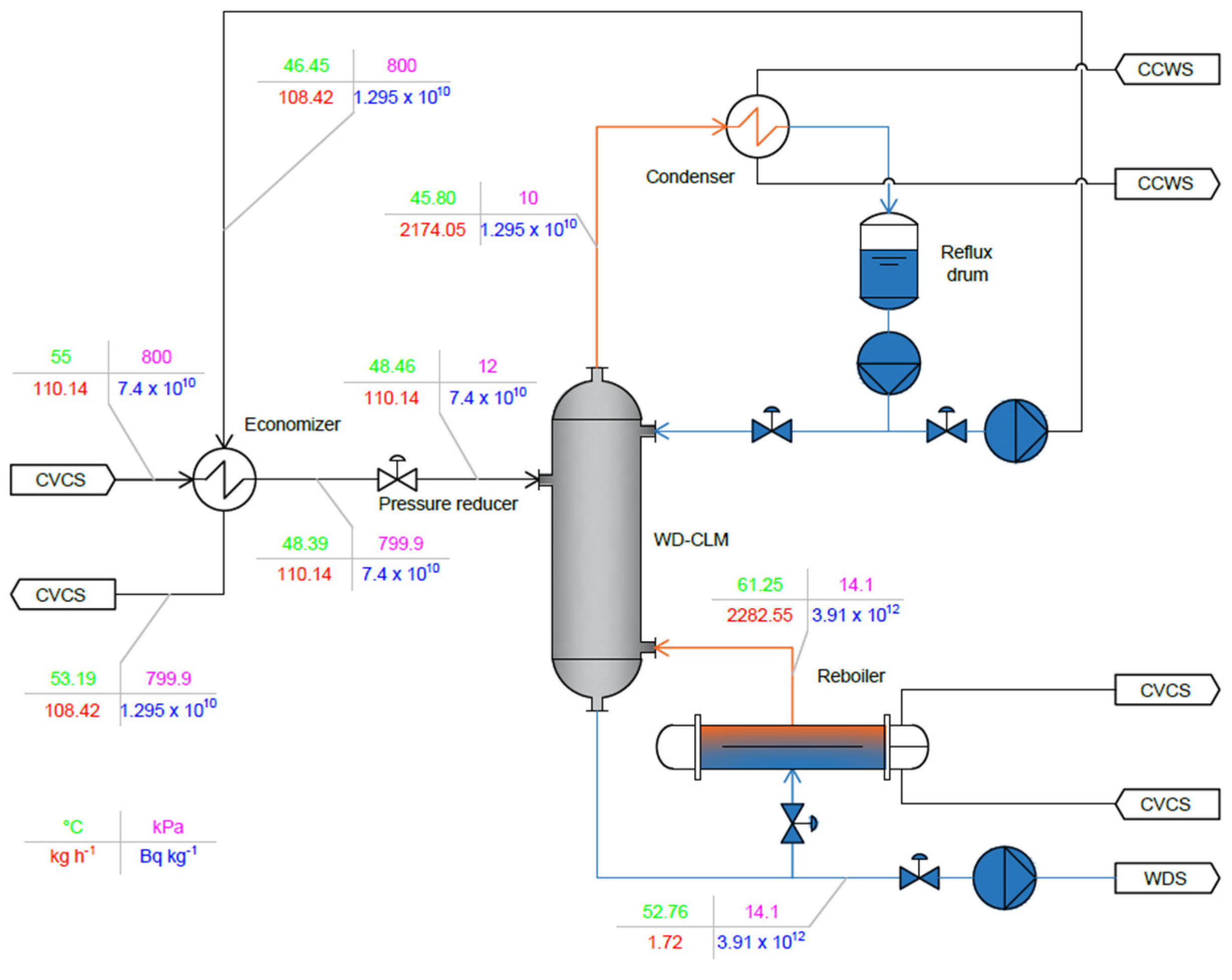
3.1. Standalone Distillation

The Standalone Distillation (STD) concept has been simulated in Aspen Plus assuming geometrical data and boundary conditions presented in Table 1. Furthermore, the reboiler is supposed to be fed on the hot side with water coming from the CVCS. The total condenser option was considered, accounting for the condensation of the whole distillate.
The scheme of the configuration, along with the main results of the process simulation in terms of temperature (green), pressure (magenta), flow rate (red), and tritium specific activity (blue), are presented in Figure 1. Tritiated water at 7.4 × 10¹⁰ Bq kg−1 passes through the economizer and the pressure reducer, reaching the operative conditions of the water distillation column (WD-CLM). Distillate, depleted in tritium, is condensed into the condenser and collected in the reflux drum. Part of this is refluxed into the column and the rest comes back to the CVCS recovering heat through the economizer. A small fraction of the bottom product, enriched in tritium, is sent to the Water Detritiation System (WDS), whereas the major portion is boiled inside the reboiler and sent back to the WD-CLM. The tritium removal rate is given by the product of the flow rate and the composition of the stream sent to the WDS and equals the tritium permeation rate at the BB. The detritiation efficiency of the system (ηCPS), defined in Equation (1), where x is the tritium specific activity in Bq kg−1 and CVCS-CPS and CPS-CVCS stand for the streams coming from and returning the CVCS, is equal to 82.5%. All the results agree with the outcomes of previous design activities [3,10].
η C P S = x C V C S C P S x C P S C V C S x C V C S C P S × 100

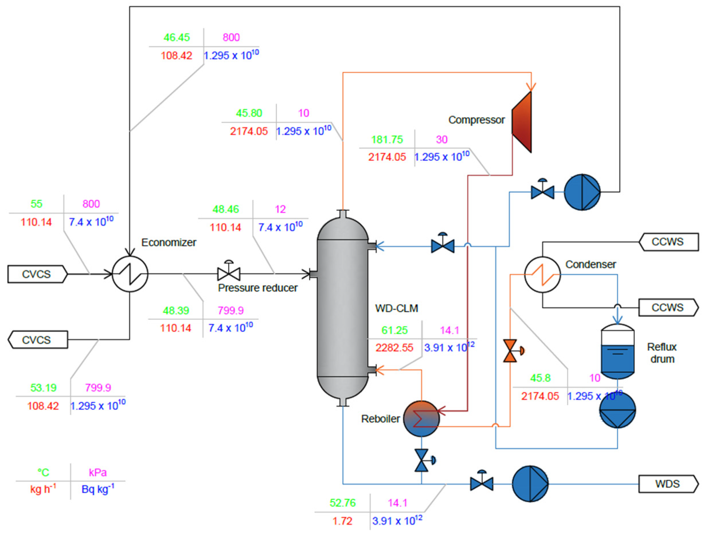
3.2. Mechanical Vapor Recompression

The schematic layout of the MVR, along with the main results obtained with Aspen Plus, are presented in Figure 2. Compared to the STD, energy content in the distillate is upgraded into the compressor and delivered to the bottom product through the reboiler. After leaving the reboiler, the distillate passes through the flash valve, restoring the pressure of 10 kPa, and the residual steam content is condensed inside the condenser. For the simulation, an isentropic transformation was preliminarily considered for the compressor.
The MVR concept introduces an additional degree of freedom to the simulation, i.e., the compressor outlet pressure. A parametric analysis investigates the effect of this parameter on the power consumption and on the reboiler dimensions, limiting the study to sub-atmospheric pressures. The main results, summarized in Table 2, highlight that by increasing the compressor outlet pressure, the outlet temperature and the net power consumption of the compressor increase. On the other hand, the required heat transfer area of the reboiler decreases. For sake of comparison, the required heat transfer area of the reboiler in the STD is 23.3 m2. The actual compressor outlet pressure is derived from a compromise between the compressor outlet temperature, the compressor net power, and the reboiler dimensions. The value of 30 kPa was selected, and the results of the process simulations are summarized in Figure 2. It is worth emphasizing that the CPS performances in terms of tritium removal rate and detritiation efficiency are the same as those of the STD.

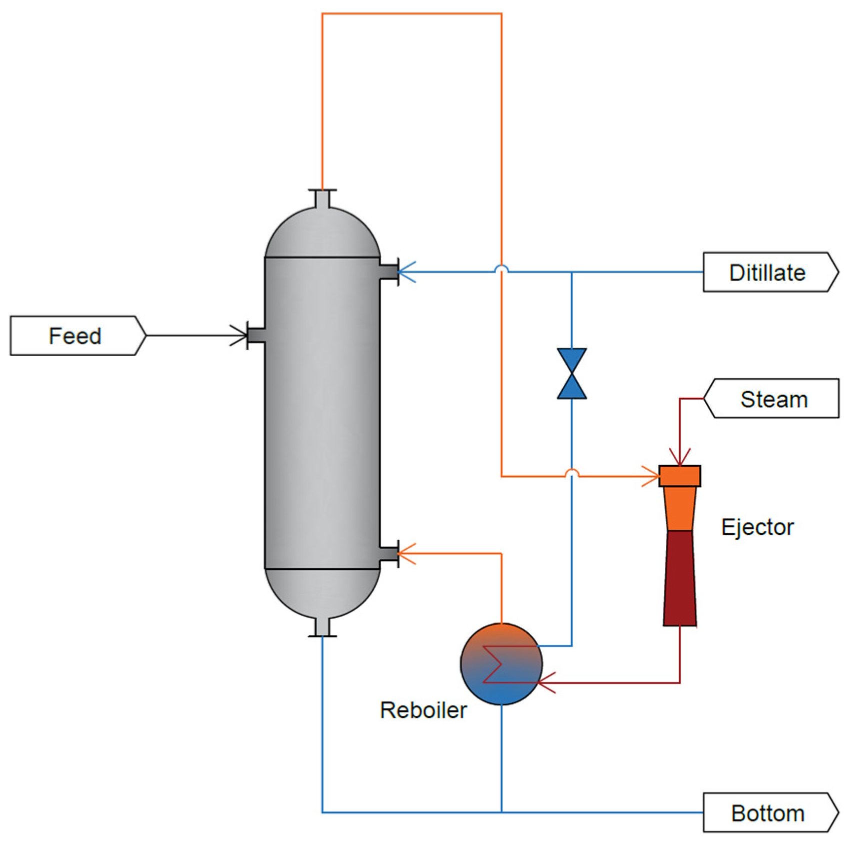
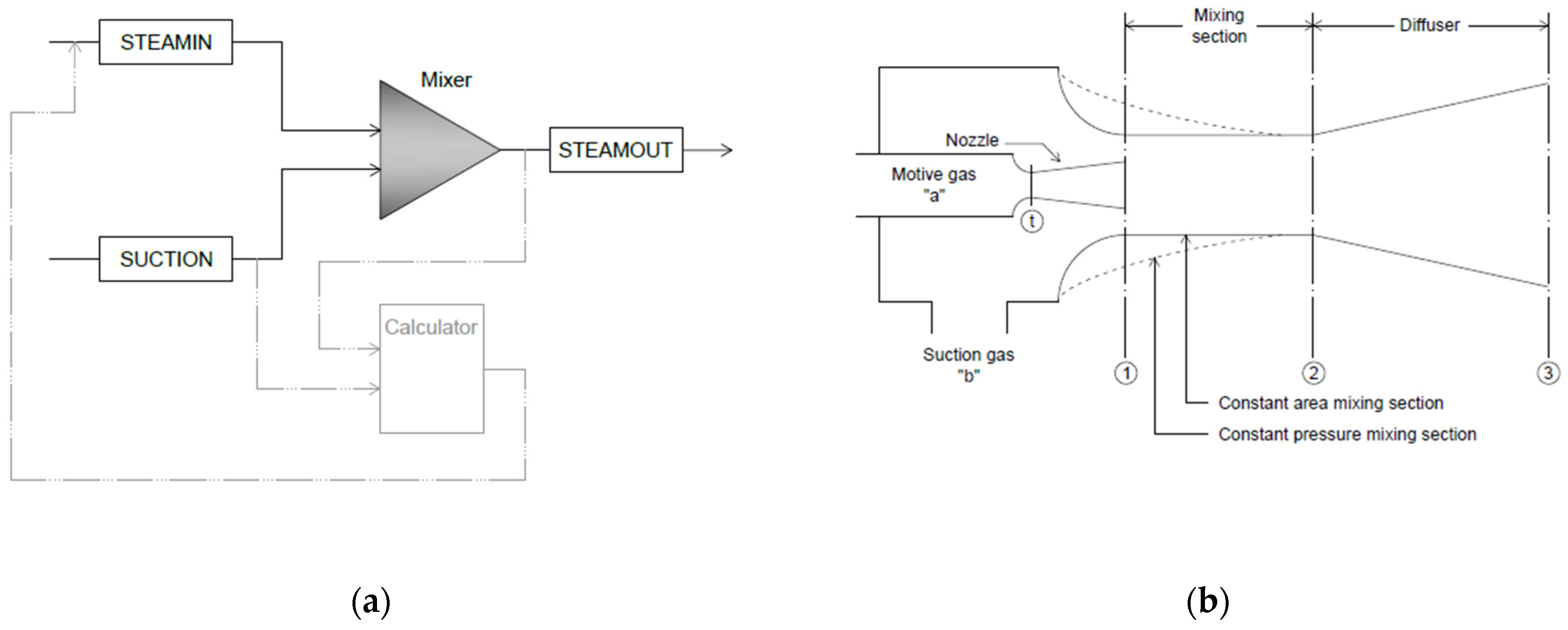
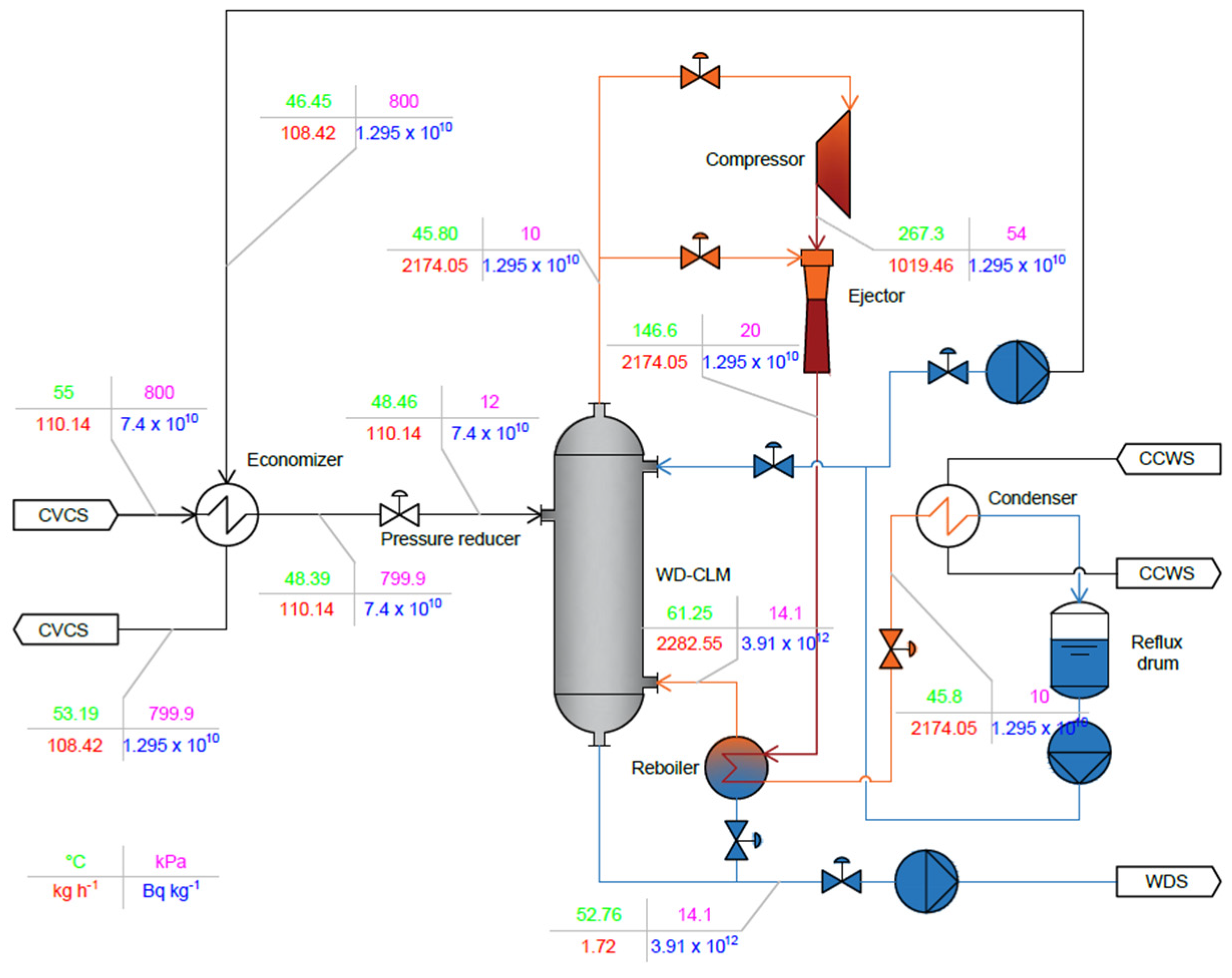
3.3. Thermal Vapor Recompression

The typical scheme of a TVR concept is presented in Figure 3. Exiting the top of the column, the distillate is sucked by the ejector, which is fed with a motive steam flow rate. Thermodynamic conditions of the mixture exiting the ejector are upgraded and used in the reboiler as a heat source. This configuration is particularly appropriate when using water, as the case of the EU-DEMO water CPS. However, focusing on the water CPS, a fundamental figure of merit in the assessment of this HPAD is the amount of the required motive steam flow rate. The best condition should be the case for which the flow rate would equal the bottom flow rate to be sent to WDS. In this case, the CPS itself accomplish with the refilling task. Instead, if the motive steam flow rate would be higher than the bottom throughput, unbalanced conditions would occur requiring the recirculation of some tritiated water that would increase complexity and tritium inventory of the system.
The key component of the TVR concept is the ejector. Such a component is not included in the default model library of Aspen Plus; thus, an ejector model was developed using the momentum balance as described by Perry [29]. The model, presented in Figure 4a, consists in two feed lines, SUCTION for the suction gas and STEAMIN for the motive gas, as well as a MIXER component, simulating the ejector itself, an outlet line, STEAMOUT, and the CALCULATOR. The latter implements the momentum balance model.
Figure 4b presents a schematic view of the ejector, showing the main notation adopted in the modelling. It employs the design curves for optimum single-stage ejector, presented by DeFrate and Hoerl [30] and reported by Perry [29]. For different area ratios between nozzle throat (t) and mixing section (point 2), A2At, expressed as:
A 2 A t = A 2 A t
where A is the flow area, and the design curves [29,30] provide the ratio of suction (b) to motive pressure (a), pbpa, over the entrainment ratio, wbwa, and over the maximum compression ratio between suction and outlet (point 3), p3pb. The three ratios are defined as:
p b p a = p b p a
w b w a = w b w a
p 3 p b = p 3 p b
where p is the pressure, and w is the mass flow rate.
Given the desired ejector outlet pressure (p3) and the suction gas pressure (pb), the CALCULATOR computes p3pb, and, employing the design curves, the pbpa is derived for a specific area ratio. From this ratio, the needed motive gas pressure is calculated and imposed to the STEAMIN feed line (see Figure 4a). Starting from the calculated pbpa, and assuming the same area ratio, the CALCULATOR computes the wbwa employing the design curves reported in [29,30]. The entrainment ratio is corrected for the temperature difference between the suction and motive gases as follows:
w b w a C = w b w a T a T b
where wbwaC is the corrected entrainment ratio, and T is the absolute temperature. Thus, given the suction gas mass flow rate, wb, the outlet mass flow rate, w3, and the required motive gas mass flow rate, wa, are calculated as:
w 3 = 1 w b w a C 1 × w b
w a = w 3 w b
Referring to the EU-DEMO water CPS, the minimum motive steam flow rate can be evaluated and compared with the flow rate sent to the WDS derived from the preliminary design of the water CPS (1.72 kg h−1) [10]. The minimum motive steam flow rate, obtained with the maximum entrainment ratio of 20, is equal to 2174 kg h−1, around three orders of magnitude higher than the WDS throughput. Therefore, the simplest configuration presented in Figure 3 cannot be adopted because a residual tritiated water flow rate would result. The solution could be to split the distillate flow rate exiting the top of the column in a smaller fraction used as motive steam and a larger fraction as suction flow rate. This solution, namely the Thermal Vapor Recompression with Compressor (TVR-CMP), is conceived to reduce the flow rate at the compressor and thus, the size of this component, compared to the MVR concept.
The TVR-CMP system is presented in Figure 5, where the main results of the process simulations are also reported. The layout is the same of the MVR except for the compression system. A fraction of the distillate throughput is sent to the ejector as suction flow rate. The rest is compressed through the compressor to the conditions needed for the motive steam flow rate of the ejector. Although the benefit of a lower compressor flow rate compared to the MVR, the number of components increases (two regulation valves and the ejector), and higher temperature and pressure are achieved at the compressor outlet.
Taking experience from the MVR simulation, in particular regarding the reboiler size, two ejector outlet pressures were considered for the simulations of the TVR-CMP: 30 kPa and 20 kPa. Per each case, a parametric analysis assessed the effect of different ejector area ratios on size and performance of the whole system. The main results for the case of 30 kPa are summarized in Table 3 (refer to Figure 4b for the subscripts’ specification).
One of the objectives of the TVR-CMP concept is the minimization of the flow rate through the compressor (i.e., the motive steam flow rate, wa), in order to reduce the size of this component. This condition is accomplished with an ejector area ratio (A2At) of 50 but, in this case, the pressure (pa) and temperature (Ta) of the motive steam are too high for the CPS. In particular, the safety relevant condition of sub-atmospheric operation is lost. The issue of the high temperature could be solved with a staged compression with intercooler, although it would affect the thermal energy of the ejector outlet stream and thus the size of the reboiler. Focusing on the power saving, the most promising case is the A2At equal to 5, allowing the minimization of the condenser and compressor power consumption while keeping acceptable reboiler size. In this case, around 70% of the distillate flow rate is routed into the compressor.
The same parametric study was repeated, assuming an ejector outlet pressure of 20 kPa, and the main results are shown in Table 4. Comparing the cases of 30 kPa and 20 kPa, the required motive flow rate is lower for the lowest ejector outlet pressure, and the thermodynamic conditions of that stream are less stringent. The power consumption is around 50% lower, whereas the required heat transfer area of the reboiler is around doubled in comparison with the 30 kPa case.
For the case of 20 kPa at the ejector outlet, the condition of minimum motive steam flow rate is achieved with the A2At equal to 100, whereas the minimization of the power consumption is obtained with an ejector area ratio of 50. As for the case of 30 kPa, the main concerns are related to the pressure and temperature at the compressor outlet, although less stringent. It is worth noting that especially for the 20 kPa case, but also for the 30 kPa for low values of A2At, the power consumption remains almost constant, changing the ejector area ratio; thus, space for further optimization is available for other components (e.g., reboiler and compressor).
Among the two ejector outlet pressures considered in this study, the case of 20 kPa ensures the power consumption minimization while keeping acceptable reboiler dimensions. Furthermore, an ejector characterized by a A2At equal to 5 guarantees less stringent thermodynamic conditions at the compressor outlet. Thus, this was considered the reference case for the TVR-CMP concept, and the main results of the process simulation are reported in Figure 5. Compared to the reference MVR, the TVR-CMP allows a compressor flow rate around 54% lower.

3.4. Results Summary

The scope of the activity is to investigate the possibility to adopt a HPAD to reduce the power consumption of the EU-DEMO water CPS. Thus, the principal figure of merit of the analysis is the total power consumption of the system, along with the power saving obtained with the HPAD concepts. Nevertheless, when using tritium (more in general, radioactive product), its inventory must be controlled and limited as much as possible, especially for a machine like EU-DEMO. Focusing on the water CPS, the main contribution to the tritium inventory of the system derives from the reboiler since it is fed with highly tritiated water (around 3.7 × 10¹² Bq kg−1) coming from the bottom of the WD-CLM [10].
When using the HPAD, additional degrees of freedom are added to the design calculations. For example, the compressor outlet pressure for the MVR concept and the operative and design parameters of the ejector for the TVR-CMP. The rationale behind the optimization of the HPAD parameters is to obtain a reboiler size as close as possible to the reboiler design of the STD while keeping acceptable operating conditions (in terms of temperature and pressure). Thus, the dimensions of the reboiler constitute the first figure of merit considered in the comparison of the different distillation concepts.
The rigorous design of the reboilers involved in the STD, MVR, and TVR-CMP was obtained with the Aspen Exchanger Design and Rating (EDR) program, and the main features are collected and compared in Table 5. For all the distillation concepts, a Tubular Exchanger Manufacturers Association (TEMA) horizontal thermosyphon was considered (TEMA type: BGM), where hot fluid (lower content of tritium) passes through the tube-side and the cold tritium-enriched flow rate boils on the shell-side. The most relevant parameter in terms of tritium inventory is the shell-side free volume, where tritium-enriched fluid is collected. As shown in Table 5, the best condition is ensured by the STD even if the reference MVR presents only an 8% increase of the free volume on the shell-side. On the other hand, the operative conditions of the TVR-CMP reference case involved a more significant increase of 85% compared to the STD. Therefore, from the point of view of the tritium inventory, the TVR-CMP is the worst case, whereas the STD and the MVR are comparable.
The comparison of the power consumption and of the power saving ensured by the considered HPADs is presented in Table 6. It is worth emphasizing that, for the STD, the power required by the reboiler is recovered from waste heat from the CVCS, and thus, the HPAD power saving is computed as follows:
P S = Q S T D ,   C N D Q H P A D , C N D + Q H P A D , C M P Q S T D ,   C N D
where PS is the power saving, Q is the power, the subscript HPAD stands for the MVR or the TVR-CMP, and the subscripts CND and CMP are condenser and compressor, respectively. Both the HPAD concepts allow a considerable power saving, reducing the CPS power consumption of around one order of magnitude compared to the preliminary design [3]. In particular, the TVR-CMP is the best choice from this point of view; however, concerns are related to the reboiler dimension and subsequent tritium inventory.
Currently, the MVR water distillation can be considered the reference solution for the EU-DEMO WCLL BB Coolant Purification System, ensuring a good compromise between the power consumption and the tritium inventory. Nevertheless, the compatibility of the compressor under a tritium-specific activity of 1.295 × 10¹⁰ Bq kg−1 deserves further analysis and verification.

4. Conclusions

The research presented in this paper follows the design activity carried out in 2022 on the Coolant Purification System of the EU-DEMO WCLL BB. In that activity, the water distillation was selected as the most promising technology for the detritiation of the primary coolant due to its intrinsic simplicity and safety. However, concern about the power consumption were highlighted. The present work deals with the assessment of best procedure to reduce power consumption of this system using Heat Pump-Assisted Distillation technologies.
First of all, a review of the HPAD developed and tested in the industry was conducted, and the most suitable solutions for the EU-DEMO water CPS were identified based on qualitative considerations. Then, a quantitative analysis was carried out with Aspen Plus in order to compare design and performances of the HPADs with the Standalone Distillation. To do this, HTO thermodynamic properties set was collected from the literature and added in Aspen Plus. Then, parametric studies were performed with Aspen Plus to optimize the operation of the two selected HPADs, i.e., the MVR and the TVR-CMP. Finally, the optimized configurations were compared with the STD, assessing the possibility to obtain a conspicuous power saving (around 80%) with both the considered HPADs. A further figure of merit considered in the assessment was the size of the reboiler, being this component the most relevant in terms of tritium inventory.
From this analysis, the MVR concept has been recognized as the most promising solution representing an excellent compromise in terms of power saving and tritium inventory of the system. Future works will be dedicated to the investigation of the compatibility between the compressor and tritiated steam and on the control procedures for the MVR concept.

Author Contributions

Conceptualization, V.N. and A.S.; methodology, V.N. and A.S.; software, V.N.; validation, V.N.; formal analysis, V.N.; investigation, V.N.; resources, A.S.; data curation, V.N. and A.S.; writing—original draft preparation, V.N. and A.S.; writing—review and editing, V.N. and A.S.; visualization, V.N. and A.S.; supervision, A.S.; project administration, A.S.; funding acquisition, A.S. All authors have read and agreed to the published version of the manuscript.

Funding

This work has been carried out within the framework of the EUROfusion Consortium, funded by the European Union via the Euratom Research and Training Programme (Grant Agreement No 101052200—EUROfusion). Views and opinions expressed are, however, those of the author(s) only and do not necessarily reflect those of the European Union or the European Commission. Neither the European Union nor the European Commission can be held responsible for them.

Institutional Review Board Statement

Not applicable.

Informed Consent Statement

Not applicable.

Data Availability Statement

Data is contained within the article.

Conflicts of Interest

The authors declare no conflicts of interest.

References

  1. Federici, G. Testing needs for the development and qualification of a breeding blanket for DEMO. Nucl. Fusion 2023, 63, 125002. [Google Scholar] [CrossRef]
  2. Santucci, A.; Incelli, M.; Noschese, L.; Moreno, C.; Di Fonzo, F.; Utili, M.; Tosti, S.; Day, C. The issue of Tritium in DEMO coolant and mitigation strategies. Fusion Eng. Des. 2020, 158, 111759. [Google Scholar] [CrossRef]
  3. Narcisi, V.; Quartararo, A.; Moscato, I.; Santucci, A. Analysis of Coolant Purification Strategies for Tritium Control in DEMO Water Primary Coolant. Energies 2023, 16, 617. [Google Scholar] [CrossRef]
  4. Spagnuolo, G.A.; Arredondo, R.; Boccaccini, L.V.; Chiovaro, P.; Ciattaglia, S.; Cismondi, F.; Coleman, M.; Cristescu, I.; D’amico, S.; Day, C.; et al. Integrated design of breeding blanket and ancillary systems related to the use of helium or water as a coolant and impact on the overall plant design. Fusion Eng. Des. 2021, 173, 112933. [Google Scholar] [CrossRef]
  5. Utili, M.; Bassini, S.; Cataldo, S.; Di Fonzo, F.; Kordac, M.; Hernandez, T.; Kunzova, K.; Lorenz, J.; Martelli, D.; Padino, B.B.; et al. Development of anti-permeation and corrosion barrier coatings for the WCLL breeding blanket of the European DEMO. Fusion Eng. Des. 2021, 170, 112453. [Google Scholar] [CrossRef]
  6. Utili, M.; Alberghi, C.; Candido, L.; Di Fonzo, F.; Papa, F.; Venturini, A. Design of the Test Section for the Experimental Validation of Antipermeation and Corrosion Barriers for WCLL BB. Appl. Sci. 2022, 12, 1624. [Google Scholar] [CrossRef]
  7. Hernandez, F.A.; Arena, O.; Boccaccini, L.V.; Cristescu, I.; Del Nevo, A.; Sardain, P.; Spagnuolo, G.A.; Utili, M.; Venturini, A.; Zhou, G. Advancements in Designing the DEMO Driver Blanket System at the EU DEMO Pre-Conceptual Design Phase: Overview, Challenges and Opportunities. J. Nucl. Eng. 2023, 4, 565–601. [Google Scholar] [CrossRef]
  8. Pereslavtsev, P.; Hernandez, F.A.; Moscato, I.; Park, J.H. Neutronic Activity for Development of the Promising Alternative Water-Cooled DEMO Concepts. Appl. Sci. 2023, 13, 7383. [Google Scholar] [CrossRef]
  9. Arena, P.; Del Nevo, A.; Moro, F.; Noce, S.; Mozzillo, R.; Imbriani, V.; Giannetti, F.; Edemetti, F.; Froio, A.; Savoldi, L.; et al. The DEMO Water-Cooled Lead-Lithium Breeding Blanket: Design Status at the End of the Pre-Conceptual Design Phase. Appl. Sci. 2021, 11, 11592. [Google Scholar] [CrossRef]
  10. Narcisi, V.; Santucci, A. Water distillation for coolant purification system of DEMO water-cooled lithium lead breeding blanket. Fusion Eng. Des. 2023, 190, 113547. [Google Scholar] [CrossRef]
  11. Kiss, A.A.; Landaeta, A.J.F.; Ferreira, C.A.I. Towards energy efficient distillation technologies—Making the right choice. Energy 2012, 47, 531–542. [Google Scholar] [CrossRef]
  12. Chen, C.; Hou, J.; Li, J.; Chen, X.; Xiao, C.; Wang, Q.; Gong, Y.; Yue, L.; Zhao, L.; Ran, G.; et al. A water distillation detritiation facility and its performance test. Fusion Eng. Des. 2020, 153, 111460. [Google Scholar] [CrossRef]
  13. Fukada, S.; Miho, Y.; Ktayama, K. Tritium separation performance of adsorption/exchange distillation tower packed with structured packing. Fusion Eng. Des. 2018, 133, 64–69. [Google Scholar] [CrossRef]
  14. Yamamoto, I.; Kaba, A.; Kanagawa, A. H2O-HTO isotope separation by distillation of water—A dynamics of HETP of SUS Dixon ring in a small packed column. Fusion Eng. Des. 1989, 10, 315–318. [Google Scholar] [CrossRef]
  15. Sugiyama, T.; Kamewaka, H.; Enokida, Y.; Yamamoto, I. Channeling Stage Model for separative analysis of packed water distillation column. Fusion Eng. Des. 1998, 39–40, 1027–1032. [Google Scholar] [CrossRef]
  16. Kembleton, R.; Morris, J.; Siccino, M.; Maviglia, F.; The PROCESS team. EU-DEMO design space exploration and design drivers. Fusion Eng. Des. 2022, 178, 113080. [Google Scholar] [CrossRef]
  17. Narcisi, V.; Ciurluini, C.; Padula, G.; Giannetti, F. Analysis of EU-DEMO WCLL Power Conversion System in Two Relevant Balance of Plant Configurations: Direct Coupling with Auxiliary Boiler and Indirect Coupling. Sustainability 2022, 14, 5779. [Google Scholar] [CrossRef]
  18. Kiss, A.A.; Smith, R. Rethinking energy use in distillation processes for more sustainable chemical industry. Energy 2020, 203, 117788. [Google Scholar] [CrossRef]
  19. Jana, A.K. Advances in heat pump assisted distillation column: A review. Energy Convers. Manag. 2014, 77, 287–297. [Google Scholar] [CrossRef]
  20. Gopichand, S.; Devotta, S. Heat pump assisted distillation. X: Potential industrial applications. Int. J. Energy Res. 1988, 12, 569–582. [Google Scholar] [CrossRef]
  21. Annakou, O.; Mizsey, P. Rigorous investigation of heat pump assisted distillation. Heat Recover. Syst. CHP 1995, 15, 241–247. [Google Scholar] [CrossRef]
  22. Yang, M.; Feng, X.; Liu, G. Heat integration of heat pump assisted distillation into the overall process. Appl. Energy 2016, 162, 1–10. [Google Scholar] [CrossRef]
  23. Wang, C.; Zhuang, Y.; Liu, L.; Zhang, L.; Du, J. Heat pump assisted extractive distillation sequences with intermediate- boiling entrainer. Appl. Therm. Eng. 2021, 186, 116511. [Google Scholar] [CrossRef]
  24. Day, C.; Battes, K.; Butler, B.; Davies, S.; Farina, L.; Frattolillo, A.; George, R.; Giegerich, T.; Hanke, S.; Hartl, T.; et al. The pre-concept design of the DEMO tritium, matter injection and vacuum systems. Fusion Eng. Des. 2022, 179, 113139. [Google Scholar] [CrossRef]
  25. Feng, X.; Berntsson, T. Critical COP for an economically feasible industrial heat-pump application. Appl. Therm. Energy 1997, 17, 93–101. [Google Scholar] [CrossRef]
  26. Sawitri, D.R.; Budiman, A. Comparative study of Heat Pump Assisted Distillation Column and Its Application for Pressure Swing Distillation Process. IOP Conf. Ser. Mater. Sci. Eng. 2020, 778, 012159. [Google Scholar] [CrossRef]
  27. Aldehani, M. Hydrogen-Water Isotope Exchange in a Trickle Bed Column by Process Simulation and 3D Computational Fluid Dynamics Modelling. Ph.D. Thesis, Faculty of Science and Technology, Engineering, Lancaster University, Lancaster, UK, 2016. Available online: https://eprints.lancs.ac.uk/id/eprint/82667 (accessed on 19 July 2023).
  28. Van Hook, W.A. Vapor Pressures of the Isotopic Waters and Ices. J. Phys. Chem. 1968, 72, 1234–1244. [Google Scholar] [CrossRef]
  29. Perry, R.H.; Green, D. Perry’s Chemical Engineers’ Handbook, 6th ed.; McGrawn Hill: New York, NY, USA, 1984. [Google Scholar]
  30. DeFrate, L.A.; Hoerl, A.E. Optimum Design of Ejectors Using Digital Computers. Chem. Eng. Prog. Symp. Ser. 1959, 55, 46. [Google Scholar]
Figure 1. CPS process simulator: scheme of the Standalone Distillation and main results.
Applsci 14 01328 g001
Figure 2. CPS process simulator: scheme of the MVR and main results.
Applsci 14 01328 g002
Figure 3. Typical scheme of a TVR HPAD.
Applsci 14 01328 g003
Figure 4. Steam ejector: (a) modelling; (b) main notation.
Applsci 14 01328 g004
Figure 5. CPS process simulator: scheme of the TVR-CMP and main results.
Applsci 14 01328 g005
Table 1. Preliminary design and operative parameters of the EU-DEMO CPS water distillation column assuming target tritium specific activity of 7.4 × 10¹⁰ Bq kg−1 into PHTS.
ParameterUnitValue
Number of columns--1
Number of theoretical stages, including condenser and reboiler--130
Feeding stage, from top--48
Packing--CY Gauze, by Sulzer
Column heightm14.17
Column diameterm1.52
Feed flow ratekg h−1110
Bottom flow ratekg h−11.72
Bottom tritium specific activityBq kg−13.7 × 10¹²
Distillate flow ratekg h−1108.28
Distillate tritium specific activityBq kg−11.628 × 10¹⁰
Boil-up flow ratekg h−12281
Reflux flow ratekg h−12172
Pressure dropskPa4.25
Table 2. MVR CPS: parametric analysis over the compressor outlet pressure.
Compressor Outlet Pressure (kPa)Compressor Outlet Temperature (°C)Compressor Net Power Required (kW)Condenser Power
(kW)
Required Heat Transfer Area of Reboiler (m2)
1592.2555.1955.4081.12
20127.8198.0798.3429.54
25156.94133.28133.5719.36
30181.75163.49163.7915.01
35203.45190.12190.4112.56
40222.80213.99214.2910.98
45240.28235.99236.279.92
50256.27255.82256.109.05
55271.01274.50274.788.42
60284.70291.79292.077.89
65297.49307.98308.277.44
70309.50323.23323.527.07
75320.83337.66337.956.75
80331.56351.37351.666.47
Table 3. TVR-CMP CPS: parametric analysis over the ejector area ratio for the outlet pressure of 30 kPa.
A2Atwa
(kg h−1)
wb
(kg h−1)
Ta
(°C)
T3
(°C)
pa
(kPa)
Condenser Power
(kW)
Compressor Power
(kW)
Required Heat Transfer Area of Reboiler
(m2)
100729.191549.71963.75368.821532398.3398.578.79
50672.991605.91730.87263.47596264.24264.5210.48
25775.661503.24585.02239.33307234.13234.4111.4
15902.191376.72504.98235.16207228.95229.2311.6
101042.541236.36446.86235.18153228.98229.2611.6
51308.18970.7348.08222.5188213.29213.5712.2
Table 4. TVR-CMP CPS: parametric analysis over the ejector area ratio for the outlet pressure of 20 kPa.
A2Atwa
(kg h−1)
wb
(kg h−1)
Ta
(°C)
T3
(°C)
pa
(kPa)
Condenser Power
(kW)
Compressor Power
(kW)
Required Heat Transfer Area of Reboiler
(m2)
100324.61954.29695.3146.3510120.4120.124.2
50383.151895.7559.6137.7272110.05109.7626
25499.11779.7456.9140.05160112.8112.525.5
15624.5711,654.3396.1145.2116119.1118.8924.4
10755.81523350.3149.689124.4124.123.6
51019.461259.4267.3146.654120.8120.524.16
Table 5. Comparison of the reboiler rigorous design for the STD, the MVR, and the TVR-CMP.
ParameterUnitSTDMVRTVR-CMP
Required heat transfer aream223.329.824.16
Excess surface%32297
Tube Outer Diameter (OD)mm25.43030
Pitchmm31.7537.537.5
Shell ODmm525610914
Tube lengthmm285025502100
Number of tubes--140166425
Shell-side free volumem30.390.420.72
Table 6. Power consumption for the Standalone Distillation.
ParameterUnitSTDMVRTVR-CMP
Reboiler powerkW1517.39 *----
Condenser powerkW1517.72163.79120.80
Compressor powerkW--163.49120.50
Total power saving%--78.484.1
* Waste heat from CVCS.
Disclaimer/Publisher’s Note: The statements, opinions and data contained in all publications are solely those of the individual author(s) and contributor(s) and not of MDPI and/or the editor(s). MDPI and/or the editor(s) disclaim responsibility for any injury to people or property resulting from any ideas, methods, instructions or products referred to in the content.

