Article

Optimization of DLTS Hinges for the Assembly of the Solar Arrays of a Communication CubeSat

by
Aikaterini Katsouli
1,
Christian Andrew Griffiths
1,* and
Euan H. Langford
1,2
1
Faculty of Science and Engineering, Swansea University, Swansea SA1 8EN, UK
2
Defense Science and Technology Laboratory (DSTL), Hampshire PO17 6AD, UK
*
Author to whom correspondence should be addressed.
Appl. Sci. 2024, 14(4), 1350; https://doi.org/10.3390/app14041350
Submission received: 20 December 2023 / Revised: 30 January 2024 / Accepted: 31 January 2024 / Published: 6 February 2024
(This article belongs to the Section Aerospace Science and Engineering)

Abstract

:
This paper demonstrates the analytical and numerical investigations for the obtainment of the predefined critical parameters of double-layer tape spring (DLTS) hinges. The DLTS hinge is utilized for the coupling between the solar panels to assist the accommodation and formulation of the assumed origami-based pattern of the solar arrays. They are examined for the assurance of safety, durability, non-permanent deformation, and stability from the stowed to the deployment configuration. Von Misses stress (σv) and steady-state moment simulations are investigated by varying the critical hinge design parameters of curvature radius (R), subtended angle (θ) and layer thickness (t). Two optimization models, Taguchi and response surface methodology/RSM, are utilized by employing the computational findings to obtain and validate the modified optimal geometric parameters within this analytical experiment. For the Taguchi method, the optimization of σv and the steady-state moment is accomplished with a t of 1.75–2.25 mm, R of 1.5–2.0 mm, and θ of 1–1.2°. Furthermore, the RSM model shows that the t, R, and θ parameters are determined to be 2.90 mm, 2 mm, and 1.35°, respectively. For optimization of the hinge design, both models should be considered for improved verification and accuracy of the results.

1. Introduction

A CubeSat is affiliated with a class of miniaturized satellites, named nanosatellites, which are predominantly launched into the low Earth orbit (LEO) by utilizing a launch vehicle or being released directly from the International Space Station [1]. Prominent utilizations of CubeSat include the investigation of the deep space environment, observation of the Earth for analysis of meteorological changes or prospective natural disasters, and telecommunications [2]. The modular structure of the CubeSat is acquired from the CubeSat unit and permits multifaceted designs with constraints in the size, shape and form factor [3]. A representative size is considered to be 1U with a standardized volume of 10 cm3 and mass less than 1.3 kg. It was initially fabricated in 1999 by Stanford and California Polytechnic universities and officially suggested as a design concept specification in 2000; however, the first launch into space occurred in June 2003 on a Rokot launch vehicle [4]. The intent of CubeSat was originally envisaged for technological and educational purposes as illustrating platforms. In the last decade, the evolution of the CubeSat has been altered from low-volume to high-volume manufacture as a result of the technological and designable simplicity, prompt and cost-effective manufacture, and deployment [5].
CubeSat is fractioned into six main systems, where solar panels are regarded as the primary generation, distribution, and control of the electrical power for the functional requisites of the CubeSat [6]. There is a frequent limitation in the orientation of the solar panels toward the sun because of the cube-shaped configuration of the satellite, and thus, supplementary deployable solar panel arrays are introduced to fulfil the power requirements for the functionality of the whole system [7]. The supplementary deployable solar panel arrays are transitioned from a folded to extended/unfolded arrangement when they reach the correct position in the low Earth orbit [8]. The solar panel arrays’ stability and reliability at extended configuration can be at risk during deployment because of sudden vibrations and solar heat radiation changes which can cause potential failure of the performance of the coupling mechanisms and insufficient power generation [9]. Ubiquitous driving/coupling mechanisms (passive mechanisms) are often dependent on torsion springs, tape springs (flexible joints), coil springs, latches, and shape memory alloys (SMAs). The passive mechanisms are preferred compared to the active mechanisms because of the non-operational power requisite, an increase in power acquisition, and a reduction in the weight and volume [10].
Researchers have scrutinized various hinges over the years to satisfy the requirements of solar array deployment such as thickness accommodation, high deployment stiffness, nominal latch-up load, and high torque margin. Therefore, flexible hinges have dominated and been utilized for the folding and deployment mechanisms of solar arrays as they are capable of self-deployment, self-latch, and elastic fold due to the release of stored strain energy [11]. They are characterized by the design’s simplicity, light weight, and evenly distributed σv before and after the deployment [11].
Throughout the years, analytical, experimental, and numerical investigations have been carried out to observe the flexible hinges’ behaviors from the stowed to deployed state by focusing on their configuration methods [12,13]. Particularly, researchers Kim and Park developed tape spring hinges (flexible hinges) for solar panel coupling which were found to satisfy the requisites for the amount of extra torque capacity and latch-up load, while optimization of the first natural frequency occurred effectively at the deployed state [14]. Furthermore, an integral flexible hinge was introduced and navigated by the researcher Yee for solar arrays, where issues were detected in the stowed and deployment configuration [15]. In the stowed position, the integral flexible hinge experienced difficulty in folding due to the large moments, while in full deployment, high-stress concentrations caused repeatability constraints [16]. It contradicted the required criteria and restraints of the solar arrays’ assembly, and consequently, the tape spring hinge was determined to be ideal, as an even stress distribution is maintained and the moments can be corrected by adding more layers of tape springs [16,17]. Multi-layer tape springs are implemented to adjust and improve the moment; however, the material contact process is required for its stowed and deployment mechanism [18]. Thus, optimized models such as response surface methodology/RSM and Taguchi are depicted and conducted by non-linear finite element analysis (FEA) to iterate the model faster, validate the numerical model, and obtain the modified optimal configuration.
This research paper will outline the analytical and numerical methodologies for the acquisition of the optimal geometric configuration of the DLTS hinge. A static finite element analysis (FEA) will be conducted by modifying and controlling the geometric parameters R, t, and θ and, as a result, exploring the σv and steady-state moment variation tendencies. Two optimization models, Taguchi and RSM, will be set for the validation and optimal obtainment of the three examined geometric parameters in order to ensure durability, non-permanent deformation, and stability throughout the deployment.
The following section establishes the design constraints that need to be satisfied for the hinge mechanism. It showcases a systematic design framework from the thickness accommodation technique to the finalized design of the coupling. Section 3 concerns the model set-up and mesh sensitivity study before undertaking the static simulations. Section 4 analyzes the data obtained by the simulations and constructs two optimized models, Taguchi and RSM, to verify and acquire the ideal geometric configuration of the coupling mechanism. Finally, conclusions are made on the final design choices identified.

2. Methodology

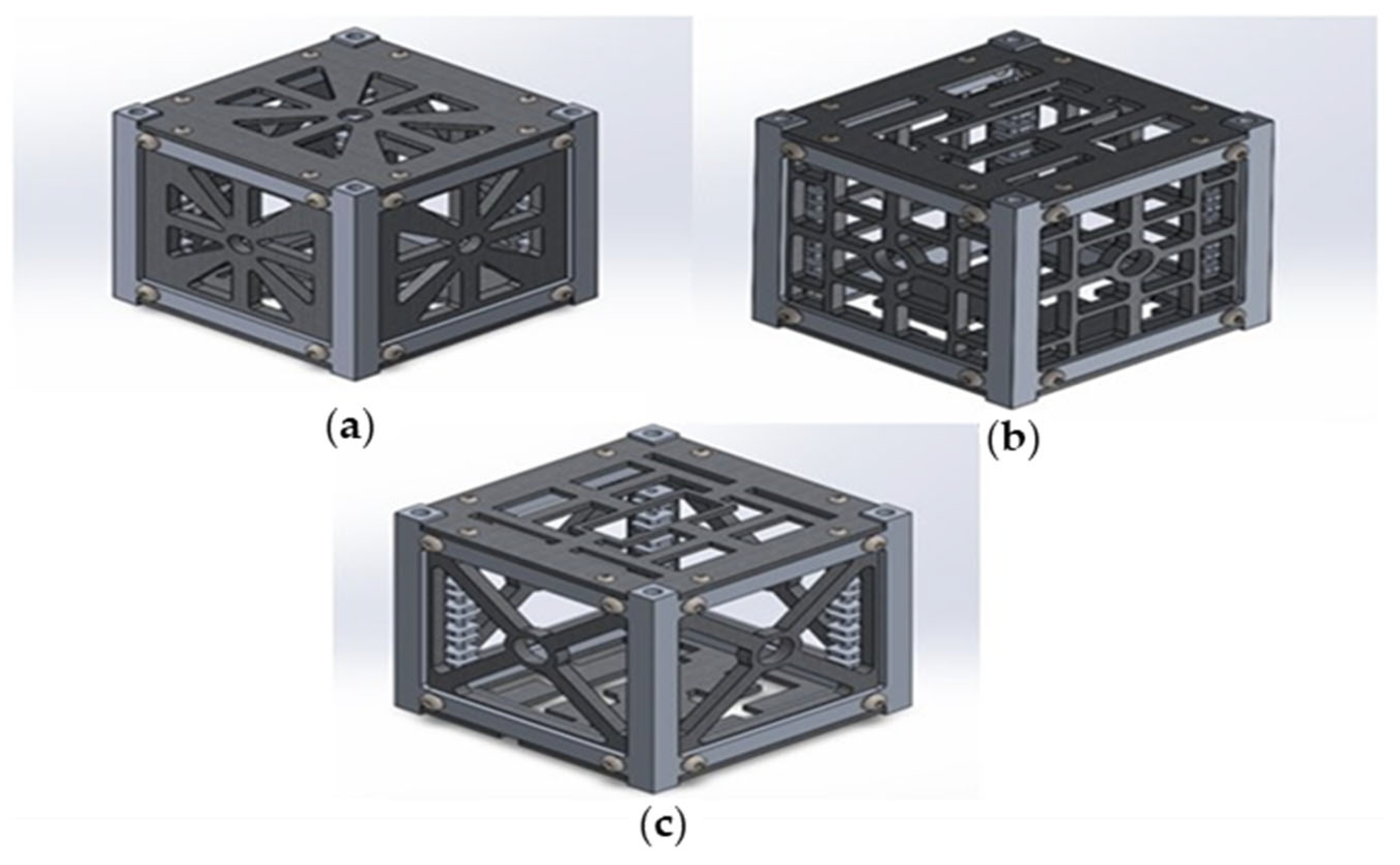
2.1. General Design Objectives of CubeSat

The design objectives were identified for the whole system to specify the hinge mechanism constraints and assumptions, leading to the investigation and optimization of the critical parameters of the DLTS hinge for reduced σv and steady-state moment. Two optimized/surrogate models were employed, Taguchi (L9 array) and RSM, for the verification between them and the obtainment of the optimal R, t, and θ parameters of the DLTS hinge. More explicitly, the Taguchi method utilizes a set of predefined orthogonal arrays to designate the parameters affecting the analysis performance and level of variation [19]. On the contrary, the RSM is considered a data approach which aims to optimize the input simulated variables and assesses the relation between acquired response surfaces and controllable input variables [20].
The design specifications for the mechanical elements of CubeSat are classified into three categories: general standards, specified motorized requirements, and the mission’s objectives and demands. The subsystem of CubeSat accommodates the payload board, ADCs (attitude determination and control system), OBC (on-board computer; communication system), and EPS (electrical power system), which are the electrical elements required to navigate and process planet surface image interpretation. Furthermore, it accommodates the motors required to actuate the coupling mechanisms of the solar arrays from the compact to the deployed state. The specifications for each of these systems influence the exterior dimensions of the subsystem, the center of gravity, the overall mass, the environment for the minimization of space debris, polytechnic devices, and optimization of the performance of the CubeSat. The general standards of 1U CubeSat are designated to be 100 ± 0.1 mm for the x and y dimensions and 114.3 ± 0.1 mm for the z dimension and a mass of <1.33 kg. The 1U skeleton structure conventionally weighs around 0.346 kg (Figure 1). The system requires simplified complexity and versatility, and the utilization of pyrotechnic devices is prohibited as it can lead to mechanical, structural, and electrical failures as well as the creation of space debris in the deployed state. The motorized requirements are focused on the design of the coupling mechanisms (hinges) for the retainment of the array from the moment of deployment until release. Hinge mechanisms operate through actuators and deploy the solar arrays with a rotation from 90° to 135° from the stowed state, generating power of 5 W to this subsystem. Within a high transition temperature environment, the design requires appropriate coupling mechanisms to minimize failures. Coupling mechanisms attribute to 10% of overall failures and thus optimization must be undertaken to maximize the durability and minimize the failure rate [21].

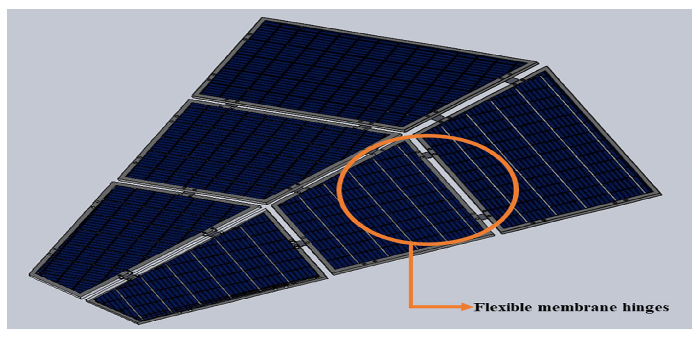
2.2. Design of Double-Layer Tape Spring (DLTS) Hinge (Coupling Mechanism)

2.2.1. Thickness Accommodation Technique

An origami-based pattern was selected and assumed for the generation of the transform of the solar array from the stowed to the deployment configuration. The flasher was implemented for this case as it initiates maximized stowage capabilities and ratios by using thick accommodation techniques, which permit each section of the analyzed system to rotate initially and fold synchronously from the stowed system.
The array pattern was not considered a zero-thickness model as the thickness of the panels could not be neglected. Therefore, various thickness accommodation techniques were investigated to prevent the self-intersection between the panels and to attain the desirable flasher foldability and low degree of freedom in the kinematic motion among the coupling origami mechanisms [22]. The flexible membrane technique was selected as an ideal option to accommodate the panels’ thickness and consequently to enable folding. The hinges were presumed to be almost zero thickness due to the usage of a thin layer of material. The technique maintained a full ROM (rough order of magnitude), indicating that the thick flasher origami pattern could maintain the parallel position of the panel faces from the stowed to the deployed state. The motion of the technique was examined to assure a low degree of freedom and perseverance of dihedral angles. It was observed that there was an inconsistent motion in the folding due to specified configurations and constraints. Thus, the problem was eliminated by minimizing the crease area of the flexible hinge, which resulted in the decrease in hinge points and degree of freedom and the obtainment of a better facilitation of the pattern without stretching or twisting the solar panels [23].
Figure 2 showcases the position of flexible membrane hinges which implement the motion of a 90° valley and mountain fold.

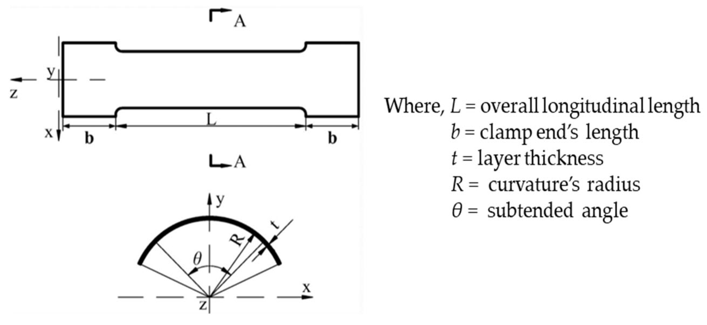
2.2.2. Double-Layer Tape Spring Hinge/DLTS

The DLTS hinge is composed of two tape springs which are positioned tightly together and are mounted to hinge brackets with the aid of bolts and spacers. The geometric configuration of a DLTS consists of the overall longitudinal length (L), the clamp end’s length (b), the layer thickness (t), the curvature’s radius (R), and the subtended angle (θ) [16]. The L and b parameters were determined to be 2.45 mm and 2 mm, respectively. The L parameter was precisely calculated to acquire the desirable creased area of the DLTS by the following equation:
L = t 2
where L = overall longitudinal length and t = thickness of each individual solar panel (3 mm).
The t, R, and θ are not fixed variables as they are defined as critical design variables; hence, they were optimized in the finite element analysis (FEA) until the appropriate numerical value was obtained. The geometric model and analyzed parameters are shown in Figure 3.
The structural complexity of the DLTS was derived from its non-linear mechanical behavior. It was established to be a key feature because it enhances robustness and restricts failure during the stowed and deployed state [16]. The non-linear mechanical behavior of the DLTS was delineated to be 2D, and two types of folds were recognized, equal sense and opposite sense bending. In equal sense bending, the DLTS exhibited low stiffness, and subsequently, when moment was applied, torsional lateral bucking appeared and numerous sharp edge kinks were generated. The sharp edge kinks were integrated into a solitary elastic fold where uniform transverse and longitudinal curvatures were developed with a positive bending moment and angle (Figure 4a). In opposite sense bending, the DLTS was displayed to procure high stiffness initially, and eventually, a snap-through formation was created by acquiring constant moment behavior. Figure 4b illustrates the opposite sense bending where transverse and longitudinal curvatures are formed with a positive bending moment and angle. A hardened steel alloy (Aermet 340) was used for the DLTS hinge because of its exceptional toughness, strength, and long-term durability.

3. Computational Modeling

3.1. Generation of Finite Element Model

The FEA was utilized for the simulation of the DLTS hinge model. Before starting the static simulation, the model was meshed by employing a quadrilateral shell element, and RFs (reference nodes) were determined and positioned at the four edges of the DLTS. Pure bending was accomplished by establishing two RFs which were connected to the edges of the DLTS end cross-section, as visualized in Figure 5. This connection occurred by employing multi-point constraints, where definite equal and opposite angular displacements were applied [17]. One of the RFs was enabled to rotate around the bending axis, while the other was set to freely rotate around the axis and translate across the entire length of the DLTS. During the folding process, if RF1 and RF2 are positioned at 90° and −90° displacement, respectively, the folding is determined to be positive. On the other hand, if RF1 and RF2 are set at −90° and 90° displacement, then a reverse folding occurs. A positive folding was selected for the achievement of the optimum folding and deploying process of the DLTS hinge. The deploying process was accomplished by reversing the directions of the rotational displacement of the RF1 and RF2 to −90° and 90°. Thus, the DLTS hinge was rotated back to its initial straight configuration.
A mesh sensitivity study (Figure 6) was conducted to retrieve the suitable quadrilateral shell element. The range of the element size was examined from 0.075 mm to 0.0175 mm, where the convergence was noticed between the 0.1 mm and 0.075 mm value. These values showcased similar maximum Von Misses stress (σv) with a percent difference of 0.74%. Thus, the slope did not fluctuate in this range, indicating a consistent convergence. The appropriate element size was determined to be 0.1, with a maximum σv of 2.32 × 10³ N/mm2 as the slope began to moderately decrease and the mesh was generated effectively after 0.075 mm.

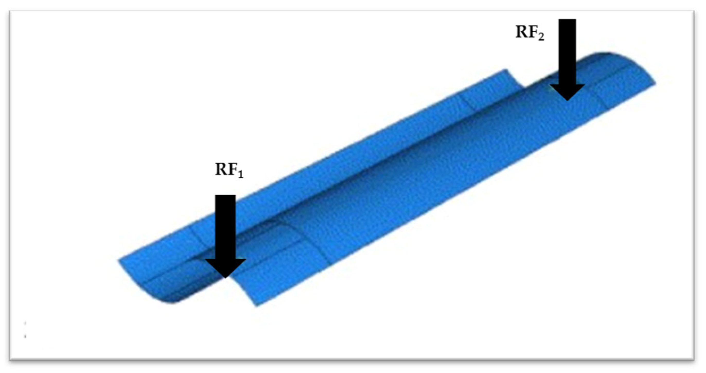
3.2. Static versus Quasi-Static Simulation

A quasi-static simulation is preferable to be implemented; however, a static simulation was employed for simplicity. The quasi-static simulation was not chosen as a lot of factors were required to be stabilized and the energy needed to be monitored throughout the folding and deploying process. More specifically, the internal and strain energy must be controlled to satisfy the condition of the kinematic-to-internal energy ratio criterion, which must be less than 1% [17]. In the quasi-static simulation, accurate results are obtained by investigating, analyzing, and contrasting various quasi-static simulation techniques such as mass scaling, which is considered a time-consuming procedure. Therefore, the static simulation was able to attain more time-efficient results as the determinants were assumed to avoid complications in the modeling and combinations of multiple simulated approaches. By acknowledging that the static simulation is not as accurate as the quasi-static one, an optimized analysis was performed to diminish the errors of the convergence of the angular displacement and to increase the precision of the obtained results, which are affected by the large deformations occurring under excessive σv.

4. Results and Discussion

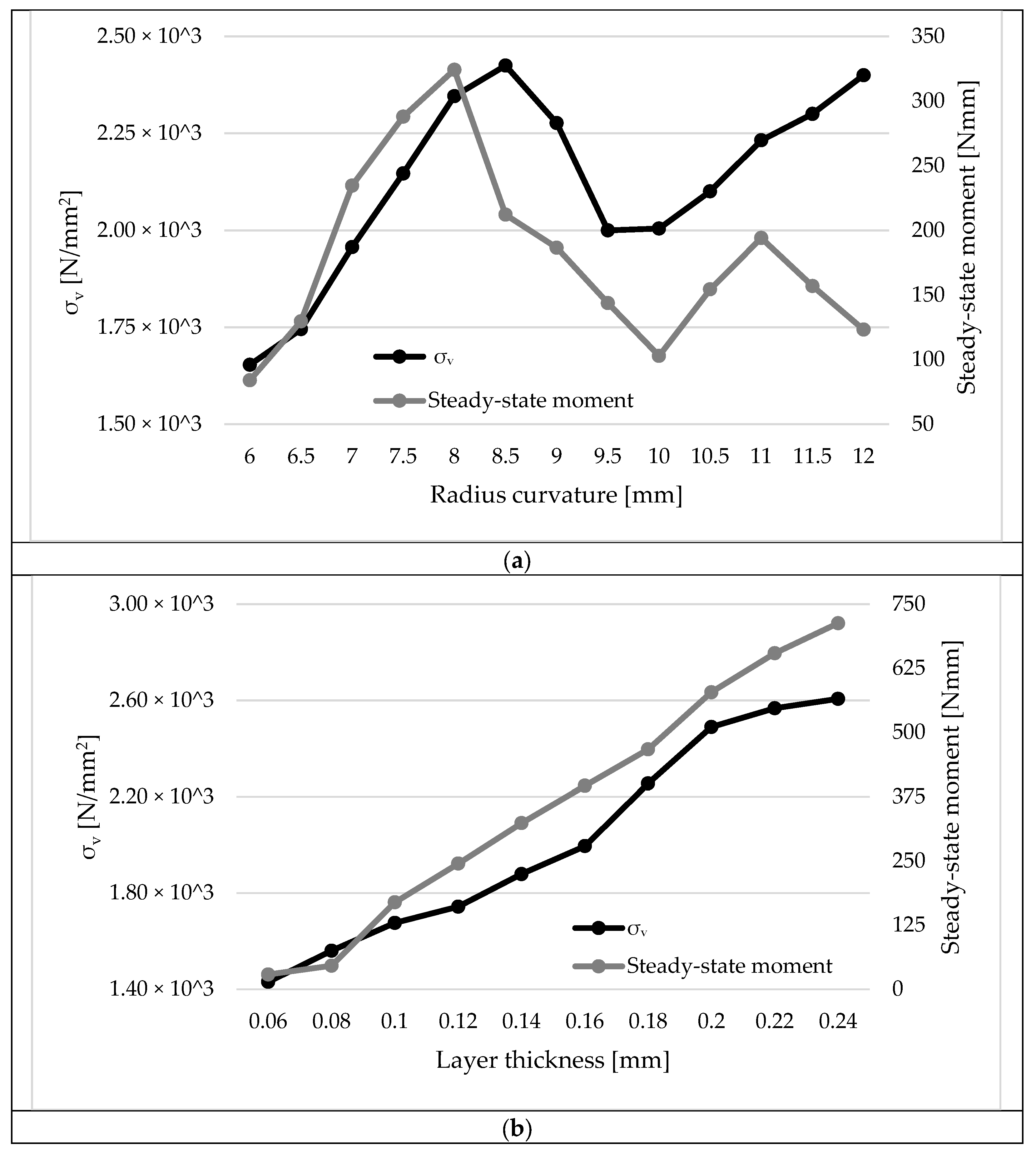
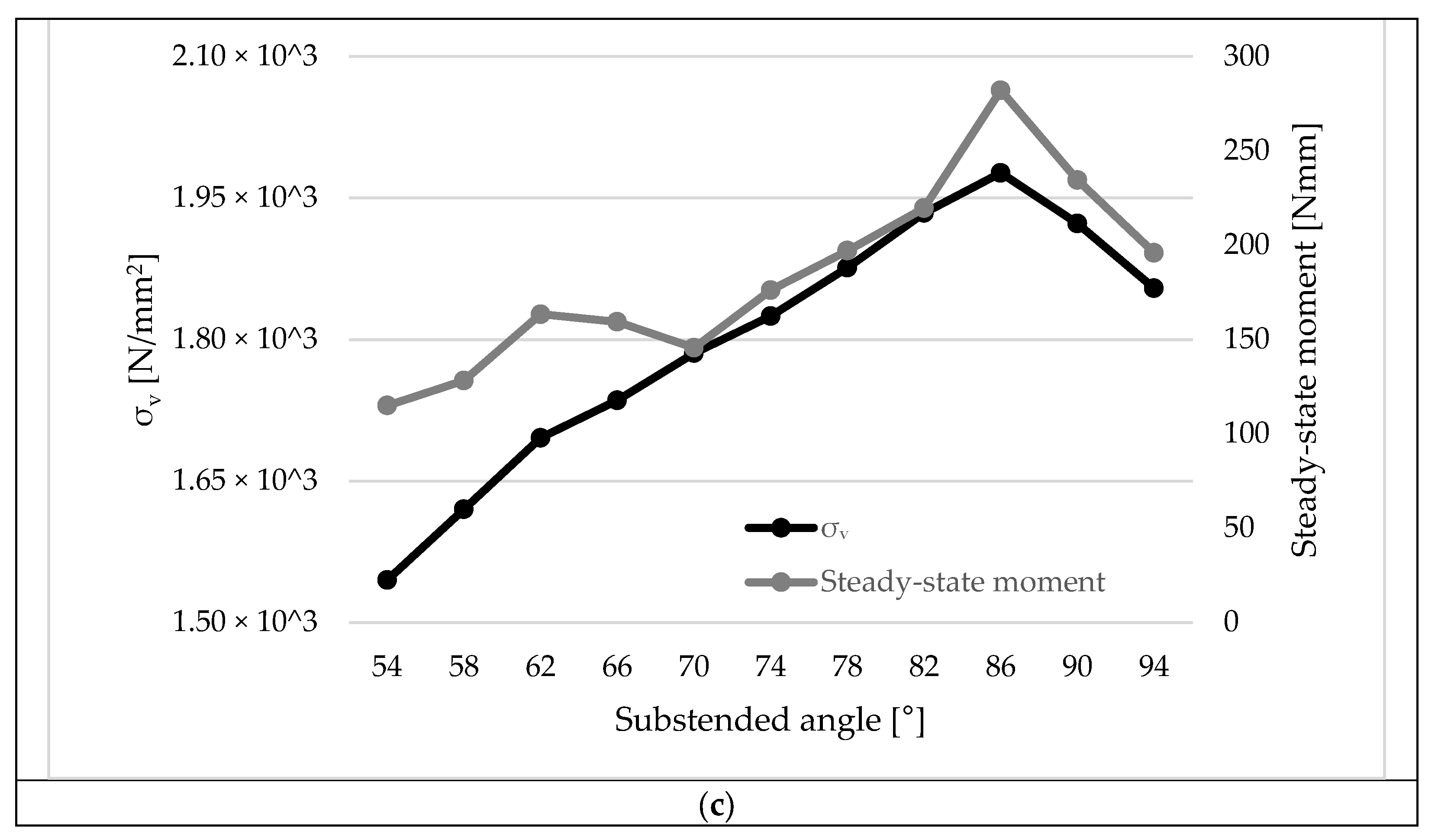
4.1. Parametric Analysis

The steady-state moment was identified to be a major feature for calculating the operation of the DLTS hinge. The geometric parameters R, t, and θ were examined and modified for the apprehension of steady-state moment variation tendencies. σv variations were explored in the stowed and deployed state to identify irreversible plastic deformation.
A parametric study was conducted by controlling and fixing t (t = 0.1 mm), L (L = 2.45 mm), and θ (90°), whereas R was alternated from 6 mm to 12 mm. From Figure 7a, it is observed that the steady-state moment values fluctuated irregularly in relation to the radius changes, which is an indication of sensitivity. The σv increased relative to R, with a maximum σv of 2.43 × 10³ N/mm2 and only a slight decrease of 17.49% between 9 and 9.5 mm.
Figure 7b showcases the parametric analysis that was implemented by modifying t from 0.06 mm to 0.24 mm and keeping constant L (2.45 mm), θ (90°), and R (6 mm). It is observed that the σv and steady-state moment results were linearly increased with respect to the thickness increase. As the moment was raised, the local σv increased, causing a slight permanent deformation in the center of the DLTS; thus the local σv levels were considered in the optimization analysis to ensure they are kept in a safe limit without causing design failure. The safe limit was specified to be less than the ultimate tensile strength of the manufacturing material of the DLTS hinge.
Figure 7c displays the effect analysis that was carried out by maintaining constant values of t (0.1 mm), L (2.45 mm), and R (6 mm) and alternating θ from 54° to 94°. The σv and steady-state moment exhibited a comparable relation with the different subtended angles. The highest peak for the σv moment was acquired at a subtended angle of 86°, followed by a decrease in both slopes.
The steady-state moment gradients for R and θ were noted to fluctuate more irregularly and presented similar maximum values, with a percentage difference of 12.96% compared to t. The σv slopes linearly increased for all three varying parameters, although there were slight drops in the slope for R and θ due to non-linearity and deformation. The maximum peaks were found to be from 1.98 × 10³ to 2.61 × 10³, with the highest percentage difference of 24.18%.

4.2. Optimization Analysis—Taguchi Model

The Taguchi array design is a well-established statistical method which is used to optimize the design parameters within this experiment. In order to make sure that the experiments are varied, an L9 Taguchi array design with three factors and three levels will be undertaken. The experimental parameters used to conduct the simulation experiments are set out in Table 1; these values will be used to identify which parameters have the greatest effect on the σv and steady-state moment.

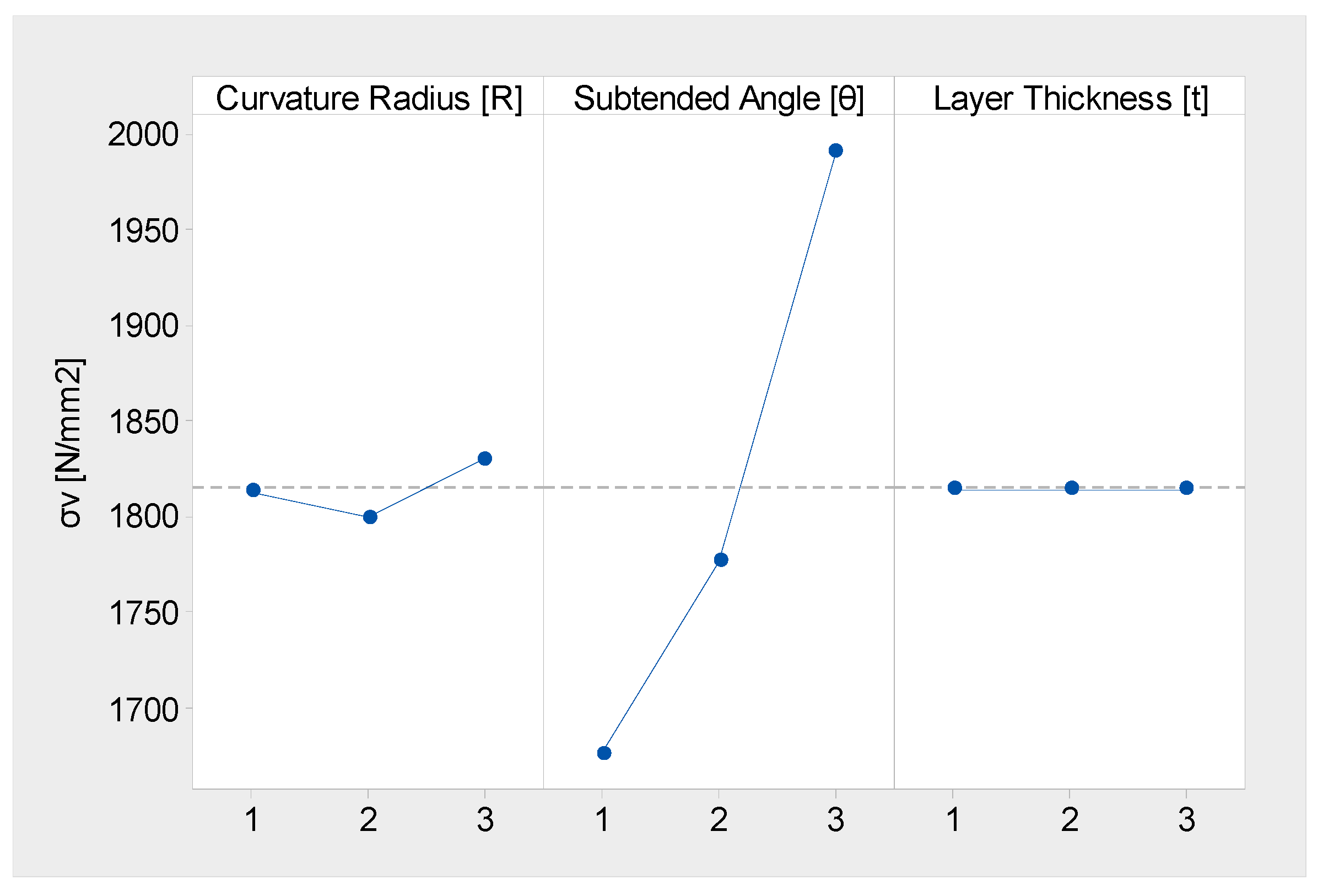
4.2.1. Main Effects and Predicted Results for σv

An analysis was conducted on the Taguchi L9 array to observe if the design parameters could be optimized in a way that the σv is reduced on the DLTS hinge. Table 2 and Figure 8 show the main effects of the parameters on the σv. For all nine experiments, the mean result is 1814.6 N/mm2. The best quality for the purpose of this research is defined as the lowest σv on the hinge. The experimental data show that the lowest σv value occurred in experiment 4 (1661.3 N/mm2), and experiment 9 produced the highest σv value (2006.7 N/mm2). For the main effect, the subtended angle is the most influential factor. As the angle is increased from 60° to 70°, the σv increases and a δ of 315 N/mm2 is observed. Curvature radius is the second most important factor, where an increase from 6.0 to 6.5 mm results in a δ of 31 N/mm2. The results for layer thickness show that there is no significant effect when modifying the value. Using DOE, it is possible to take the factor settings that provide an optimum result and predict the average response for this combination of control factor levels. The objective is to determine the factor where the levels minimize σv. The results in Table 2 show that by using a radius curvature of 6.0 mm, a subtended angle of 60°, and a layer thickness of 0.1 mm, a σv of 1661 N/mm2 can be expected. This is an improvement of 17.2% when compared to the measured response from experiment 9.

4.2.2. Main Effects and Predicted Results for Steady-State Moment

Table 3 and Figure 9 show the main effects of the parameters on the steady-state moment. For all nine experiments, the mean result is 209.4 N/mm2. Similar to σv, the lowest moment on the hinge occurred in experiment 4 (133.93 N/mm), and experiment 9 produced the highest value (284.6 N/mm). For the main effect, the subtended angle is the most influential factor, while curvature radius and layer thickness do not have a significant effect when modifying the value. Using a radius curvature of 6.0 mm, a subtended angle of 60°, and a layer thickness of 0.1 mm, a predicted response of 133.9 N/mm can be expected. This is an improvement of 36.0% when compared to the measured response from experiment 9.

4.2.3. Interaction Optimization Results for σv and Steady-State Moment

When designing the DLTS hinge components, a low σv and high strength contribute to the overall performance. The research has shown that the process settings have an influence on the part specifications, and there are options to consider when selecting a particular criterion. In this section, contour plots are used to examine the relationship between the selected response variables of σv and the steady-state moment and three predictor variables, curvature radius, subtended angle, and layer thickness.
With a focus on optimizing σv to be below 1700 N/mm2, the following observations are found:
  • It is possible to achieve a low σv with a reduced subtended angle (<1.5°) and a curvature radius between 1.5 and 2.25 mm (Figure 10a).
  • Similarly, a low σv can be achieved with a subtended Angle (<1.5°) and a layer thickness between 1.75 and 2.75 mm (Figure 10b).
  • A layer thickness between 1.75 and 2.5 mm and a curvature radius of 1.5–2.0 mm results in a low σv (Figure 10c).
When optimizing the steady-state moment below 150 N/mm2, the following observations are found:
  • It is possible to achieve a low moment with a reduced subtended angle (<1.2°) and a curvature radius between 1.25 and 2.0 mm (Figure 10d).
  • A low σv can also be achieved with an angle of 1.5° and a layer thickness between 1.75 and 2.2 mm (Figure 10e).
  • A layer thickness between 1.75 and 2.25 mm and a curvature radius of 1.25–2.0 mm results in a low σv (Figure 10f).
A compromise for a low σv and steady-state moment is possible. Optimization is achieved with a layer thickness of 1.75–2.25 mm, a curvature radius of 1.5–2.0 mm, and an angle of 1–1.2°.

4.3. Optimization Analysis—RSM Model

The optimization analysis was set for the maximization of the steady-state moment, where the maximum σv was applied as a constraint. The excessive σv could generate permanent damage on the DLTS hinge and prevent deployment performance. Therefore, the constrained max σv was maintained below the allowable σv of the DLTS hinge material. The steady-state moment was established to be an optimized objective as it is a major characteristic for the maneuverability of the hinge. The θ and t variables are identified as critical deign parameters through the primary and secondary sequence study. The R parameter was negligible as it did not directly impact the objective and was maintained at 2 mm. The optimized decisions are illustrated by the following mathematical configurations and symbols [25].
Objective = M s   ( maximization )
Constraint :     σ m a x σ ¯
Critical   parameters :   x i _ x i x i ¯
i = 1 , ,   n
where,
  • Ms = steady-state moment of DLTS hinge
  • σmax = maximum σv in stowed state
  • x i _ = lower limit of the critical design parameter
  • x i ¯ = upper limit of the critical design parameter
  • n = number of total critical design parameters
Response surface methodology/RSM was selected for this engineering optimization application. RSM forms an approximate representation where a relation is acquired between the critical design parameters and objectives by employing first and second-order polynomial functions [17]. The RSM approach was carried out by varying the t and θ parameters from 0.06 mm to 0.24 mm, and 54° to 94°, respectively. The sample points were extracted from the two four-factor methods. The σv and steady-state outcomes were explored by utilizing computational simulation results. The following polynomial equation was employed for the acquisition of the undetermined parameters and, consequently, the obtainment of the function values of the σv and steady-state moment [24].
F x = a 1 + i = 1 n a i + 1 x i + i = 1 n 1 j = i + 1 n a i j x i x j + i = 1 n a i i x i 2
Where,
  • F(x) = estimation of the function’s true response
  • a = undetermined parameters
The third order of the polynomial equation was utilized and was run through MATLAB R2021b version to obtain the objective and constraint function, which showcased the yielding values of the steady-state moment and σv. The absolute value of the objective and constraint function was determined to be 0.00109 and 0.00008, respectively. The relative error value between MATLAB and the simulation for the objective and constraint function was estimated to be 8.23% and 5.67%, correspondingly.
The accuracy of the objective and constraint function values were assessed by implementing the complex (R2) and modified complex ( R a d j 2 ) correlation coefficients, which are preferable when close to one another for precision and accuracy of the function [18]. R2 and R a d j 2 were proven by the following deviations [26].
R 2 = 1 i = 1 m ( y i y ˇ i ) 2 i = 1 m ( y i y ~ ) 2
R a d j 2 = 1 m 1 m N 1 R 2
Where,
  • y ~ i = response of sample point with ith terms (FEA)
  • y ~ = mean response
  • yi = response of sample point with ith terms (MATLAB)
  • m = number of design points
  • N = number of basic functions
R2 and R a d j 2 for the max σv response were obtained to be 0.99453 and 0.99324, with a percentage difference of 0.12%. Moreover, the R2 and R a d j 2 coefficients for the steady-state moment were found to be 0.99654 and 0.99614, with a percentage difference of 0.04%. These two deviations were good indicators of accuracy and thus verified that two responses fulfilled the criterion of accuracy.
The final step before obtaining the optimal design solution was the application of the LSGRG algorithm (large-scale generalized reduced gradient), which was able to control equality and inequality restraints [18]. The design parameter intervals of θ = [45, 90] and t = [0.05, 0.15] were added in the algorithm, as well as the primary point of x = [0.1, 65.0] T. The maximum σv was kept lower than the depicted allowable σv of 1.9 × 10³ N/mm2 to assure stability, durability, and safety of the DLTS hinge in the stowed state. The LSGRG algorithm ran multiple simulations to acquire the optimal design parameters, and thus, 27 iterations were required. Table 4 shows the modifications of the critical design parameters, max σv, and steady-state moment from the original to the optimal design of the DLTS hinge. From Table 4, it is observed that the θ variable was reduced by 97.92%, whereas the t variable was increased by 94.83%. The max σv and steady-state moment values were decreased and elevated by 11.58% and 13.34%, respectively.

5. Conclusions

The double-layer tape spring (DLTS) hinge is employed to facilitate the connection between the flasher solar panels, supporting the adaptation and realization of the assumed origami-based pattern in the solar arrays. This study aimed to discern the crucial parameters of the DLTS hinge during the transition from the stowed to the deployment configuration. The design methodology involved simulations to obtain the optimal solution for the critical design parameters of the DLTS hinge.
The critical geometric parameters R, θ, and t were identified and σv and steady-state moment simulations were undertaken for the DLTS hinge in the stowed and deployed state. After the extraction of the computational results, optimization was conducted using Taguchi DOE and RSM. In the Taguchi L9 array method, a design with three factors and three levels was employed to identify parameters with a low σv and steady-state moment. Contour plots were utilized to investigate the relationship between the selected response variables of σv and steady-state moment and the three denoted critical parameters. In the case of the RSM model, an LSGRG algorithm was employed, and the maximum σv was identified as a constraint to eliminate the deformations and failure of the DLTS hinge. The t and θ parameters were denoted as critical design parameters and the R parameter was neglected.
The goal of this research is to enhance the integration of solar panels, minimizing the risk of failure during service. The findings have identified crucial parameters for producing a preliminary specification for the first stage of development. The key outcomes from the computational experimentation are as follows:
  • The predicted lowest σv and steady-state moment were estimated to be 1661 N/mm2 and 133.9 N/mm by setting an R of 6.0 mm, a θ of 60°, and a t of 0.1 mm, utilizing the RSM model.
  • Optimization was achieved by keeping σv below 1700 N/mm2 and the steady-state moment below 150 N/mm2.
  • Consequently, the optimum parameters of t, R, and θ were determined to be between 1.75 and 2.25 mm, 1.50 and 2.0 mm, and 1 and 1.2°, respectively.
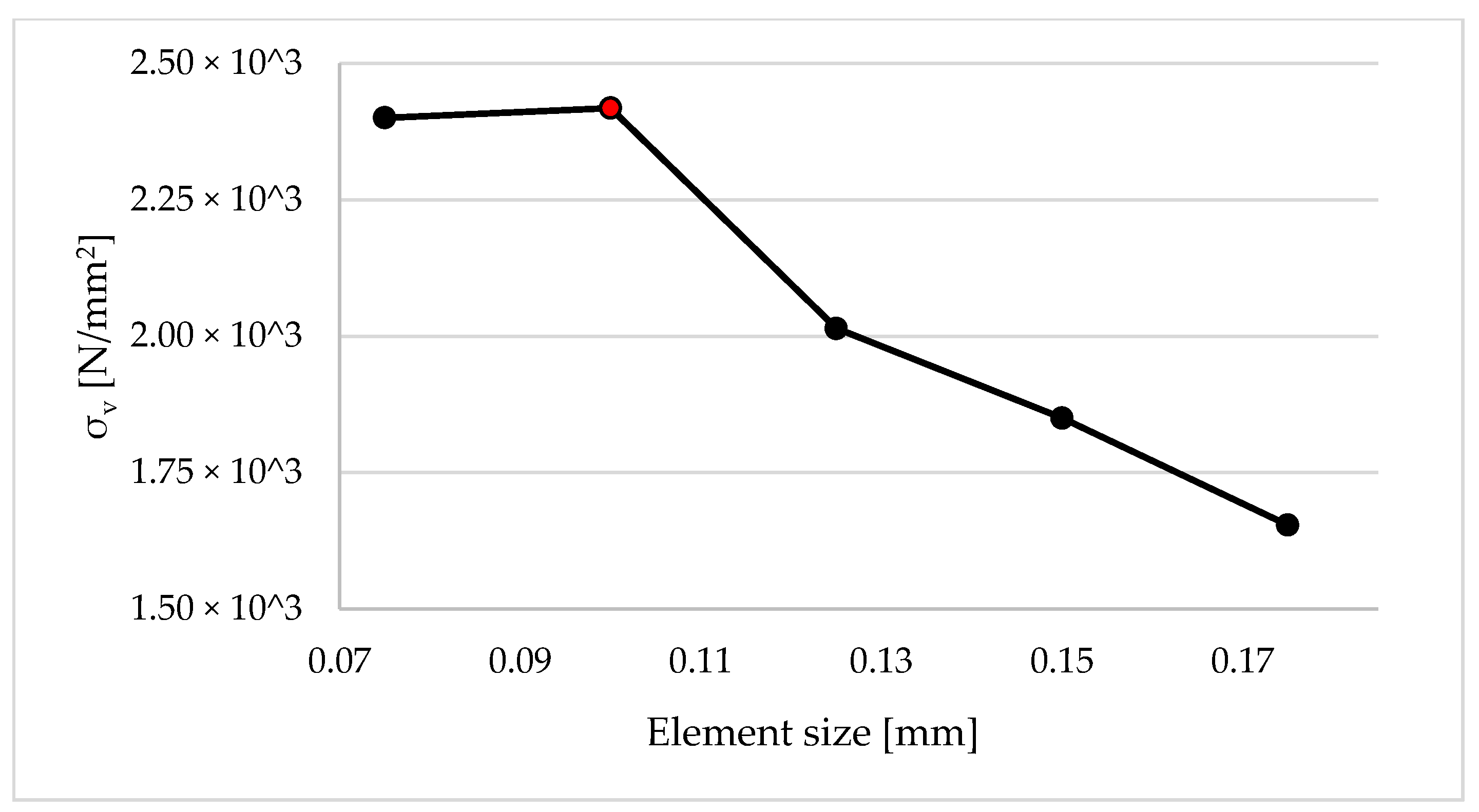
  • A safe limit of maximum σv was determined for the avoidance of permanent deformation and degradation of the DLTS hinge, which could not exceed the 2.43 × 10³ N/mm2 value.
  • Following this, the accuracy criterion for the max σv and steady-state moment yielding value was satisfied by determining the percentage difference between R2 and R a d j 2 for the two responses.
  • Subsequently, the optimum values of the t and θ parameters were 2.90 mm and 1.35°, with a max σv of 1.49 × 10³ N/mm2 and steady-state moment of 145.76 Nmm.
  • The design goal of the DLTS hinges was to accommodate the thickness of the flasher pattern and rotate 90°. The optimum values of t and θ achieved this with a reduced σv to the system, and hence, sufficient stability of the DLTS hinges was accomplished to ensure safe launch conditions, withstand the harsh environmental conditions, rotate appropriately the solar panels for the obtainment of power, and expand the life service of the whole system.
  • Future research investigations will require a life cycle assessment and on-site validation, with a focus on the deformation and degradation of DLTS hinges. Additionally, multi-layer tape spring hinges combined with different CubeSat solar array origami patterns are of interest.

Author Contributions

Investigation, writing—review & editing, A.K.; Writing—review & editing, C.A.G.; Supervision, E.H.L. All authors have read and agreed to the published version of the manuscript.

Funding

This research received no external funding.

Institutional Review Board Statement

Not applicable.

Informed Consent Statement

Not applicable.

Data Availability Statement

The data presented in this study are available on request from the corresponding author. The data are not publicly available due to a proprietary agreement with the research partner.

Acknowledgments

The authors would like to acknowledge the support of the Future Manufacturing Research Institute, the College of Engineering, Swansea University, and the Defense Science and Technology Laboratory’s (DSTL) Platform Systems Division test and evaluation team in the UK.

Conflicts of Interest

The authors declare no conflict of interest.

References

  1. Jacobs, M.; Selva, D. A CubeSat catalog design tool for a multi-agent architecture development framework. In Proceedings of the IEEE Aerospace Conference, Big Sky, MT, USA, 7–14 March 2015; pp. 1–10. [Google Scholar]
  2. Levchenko, I.; Bazaka, K.; Ding, Y.; Raitses, Y.; Mazouffre, S.; Henning, T.; Klar, P.J.; Shinohara, S.; Schein, J.; Garrigues, L.; et al. Space micropropulsion systems for Cubesats and small satellites: From proximate targets to furthermost frontiers. Appl. Phys. Rev. 2018, 5, 011104. [Google Scholar] [CrossRef]
  3. Popescu, O. Power Budgets for CubeSat Radios to Support Ground Communications and Inter-Satellite Links. IEEE Access 2017, 5, 12618–12625. [Google Scholar] [CrossRef]
  4. Swartwout, M. The first one hundred CubeSats: A statistical look. J. Small Satell. 2013, 2, 213–233. [Google Scholar]
  5. Poghosyan, A.; Golkar, A. CubeSat evolution: Analyzing CubeSat capabilities for conducting science missions. Prog. Aerosp. Sci. 2017, 88, 59–83. [Google Scholar] [CrossRef]
  6. Xilun, D.I.; Xin, L.I.; Kun, X.U.; Qiaolong, Y.A.; Hailing, P.U. Study on the behavior of solar array deployment with root hinge drive assembly. Chin. J. Aeronaut. 2012, 25, 276–284. [Google Scholar]
  7. Oh, H.-U.; Park, T. Experimental feasibility study of concentrating photovoltaic power system for cubesat applications. IEEE Trans. Aerosp. Electron. Syst. 2015, 51, 1942–1949. [Google Scholar] [CrossRef]
  8. Li, Y.; Wang, Z.; Wang, C.; Huang, W. Effects of torque spring, CCL and latch mechanism on dynamic response of planar solar arrays with multiple clearance joints. Acta Astronaut. 2017, 132, 243–255. [Google Scholar] [CrossRef]
  9. Li, Y.; Wang, C.; Huang, W. Rigid-flexible-thermal analysis of planar composite solar array with clearance joint considering tor-sional spring, latch mechanism and attitude controller. Nonlinear Dyn. 2019, 96, 2031–2053. [Google Scholar] [CrossRef]
  10. Solís-Santomé, A.; Urriolagoitia-Sosa, G.; Romero-Ángeles, B.; Torres-San Miguel, C.R.; Hernández-Gómez, J.J.; Medina-Sánchez, I.; Couder-Castañeda, C.; Grageda-Arellano, J.I.; Urriolagoitia-Calderón, G. Conceptual design and finite element method valida-tion of a new type of self-locking hinge for deployable CubeSat solar panels. Adv. Mech. Eng. 2019, 11, 1687814018823116. [Google Scholar] [CrossRef]
  11. Soykasap, Ö. Analysis of tape spring hinges. Int. J. Mech. Sci. 2007, 49, 853–860. [Google Scholar] [CrossRef]
  12. Mansfield, E.H. Large-deflexion torsion and flexure of initially curved strips. Proc. R. Soc. Lond. Ser. A Math. Phys. Sci. 1973, 334, 279–298. [Google Scholar] [CrossRef]
  13. Seffen, K.; You, Z.; Pellegrino, S. Folding and deployment of curved tape springs. Int. J. Mech. Sci. 2000, 42, 2055–2073. [Google Scholar] [CrossRef]
  14. Yuanyuan, L.I.; Meng, L.I.; Yufei, L.I.; Xinyu, G.E.; Chengbo, C.U. Parameter optimization for torsion spring of deployable solar array system with multiple clearance joints considering rigid–flexible coupling dynamics. Chin. J. Aeronaut. 2022, 35, 509–524. [Google Scholar]
  15. Yee, J.C. Thin CFRP Composite Deployable Structures. Ph.D. Thesis, University of Cambridge, Cambridge, UK, 2006. [Google Scholar]
  16. Mallikarachchi, H.M. Thin-Walled Composite Deployable Booms with Tape-Spring Hinges. Ph.D. Thesis, University of Cambridge, Cambridge, UK, 2011. [Google Scholar]
  17. Fernandes, P.; Pinto, R.; Correia, N. Design and optimization of self-deployable damage tolerant composite structures: A review. Compos. Part B Eng. 2021, 221, 109029. [Google Scholar] [CrossRef]
  18. Yang, H.; Liu, R.; Wang, Y.; Deng, Z.; Guo, H. Experiment and multiobjective optimization design of tape-spring hinges. Struct. Multidiscip. Optim. 2015, 51, 1373–1384. [Google Scholar] [CrossRef]
  19. Sibalija, T.V.; Majstorovic, V.D. An integrated approach to optimise parameter design of multi-response processes based on Taguchi method and artificial intelligence. J. Intell. Manuf. 2012, 23, 1511–1528. [Google Scholar] [CrossRef]
  20. Asiltürk, I.; Neşeli, S. Multi response optimisation of CNC turning parameters via Taguchi method-based response surface analysis. Measurement 2012, 45, 785–794. [Google Scholar] [CrossRef]
  21. Bolanos, D.S. Selecting and Optimizing Origami-Based Patterns for Deployable Space Systems. Ph.D. Thesis, Brigham Young University, Provo, UT, USA, 2022. [Google Scholar]
  22. Lang, R.J.; Tolman, K.A.; Crampton, E.B.; Magleby, S.P.; Howell, L.L. A review of thickness-accommodation techniques in origami-inspired engineering. Appl. Mech. Rev. 2018, 70, 010805. [Google Scholar] [CrossRef]
  23. Tolman, K.A.; Lang, R.J.; Magleby, S.P.; Howell, L.L. Split-vertex technique for thickness-accommodation in origami-based mechanisms. In Proceedings of the International Design Engineering Technical Conferences and Computers and Information in Engineering Conference, Cleveland, OI, USA, 6–9 August 2017; Volume 58189, p. V05BT08A054. [Google Scholar]
  24. Ye, H.; Zhang, Y.; Yang, Q.; Xiao, Y.; Grandhi, R.V.; Fischer, C.C. Optimal design of a three tape-spring hinge deployable space structure using an experimentally validated physics-based model. Struct. Multidiscip. Optim. 2017, 56, 973–989. [Google Scholar] [CrossRef]
  25. Wilson, L.; Gdoutos, E.E.; Pellegrino, S. Tension-Stabilized Coiling of Isotropic Tape Springs. Int. J. Solids Struct. 2020, 188, 103–117. [Google Scholar] [CrossRef]
  26. Jin, H.; Jia, Q.; An, N.; Zhao, G.; Ma, X.; Zhou, J. Surrogate modeling accelerated shape optimization of deployable composite tape-spring hinges. AIAA J. 2022, 60, 5942–5953. [Google Scholar] [CrossRef]
Figure 1. Evolution of the subsystem’s skeleton of the CubeSat from initial (a) to final (c) CAD model.
Applsci 14 01350 g001
Figure 2. Membrane technique—CAD model.
Applsci 14 01350 g002
Figure 3. Geometric configuration of the DLTS hinge [24].
Applsci 14 01350 g003
Figure 4. (a) Positive folding/equal sense bending of DLTS; (b) reverse folding/opposite sense bending of DLTS [11].
Applsci 14 01350 g004
Figure 5. FEA analysis—static model generation [11].
Applsci 14 01350 g005
Figure 6. Mesh sensitivity study.
Applsci 14 01350 g006
Figure 7. σv and steady-state moment variations for (a) radius curvatures (R), (b) layer thickness (t), and (c) subtended angle ).
Applsci 14 01350 g007aApplsci 14 01350 g007b
Figure 8. Main effects plot for σv.
Applsci 14 01350 g008
Figure 9. Main effects plot for steady-state moment.
Applsci 14 01350 g009
Figure 10. Contour plots for σv and steady-state moment.
Applsci 14 01350 g010
Table 1. L9 orthogonal array of DLTS hinge design parameters.
ExperimentRadius Curvature [mm]Subtended Angle [°]Layer Thickness [mm]
15.5600.10
25.5650.15
35.5700.20
46.0600.10
56.0650.15
66.0700.20
76.5600.10
86.5650.15
96.5700.20
Table 2. Response for mean σv.
Descriptive StatisticsMeanSE MeanStDev
1814.646.6139.9
LevelCurvature Radius [R]Subtended Angle [θ]Layer Thickness [t]
11813 N/mm21676 N/mm21815 N/mm2
21800 N/mm21777 N/mm21815 N/mm2
31830 N/mm21991 N/mm21815 N/mm2
Difference (δ)31 N/mm2315 N/mm20 N/mm2
Rank importance213
Prediction1661 N/mm2 (lowest σv)
Table 3. Response for mean steady-state moment.
Descriptive StatisticsMeanSE MeanStDev
209.419.759.1
LevelCurvature Radius [R]Subtended Angle [θ]Layer Thickness [t]
1206.9 [N/mm]140.3 [N/mm]209.4 [N/mm]
2203.1 [N/mm]212.2 [N/mm]209.4 [N/mm]
3218.3 [N/mm]275.7 [N/mm]209.4 [N/mm]
Difference (δ)15.2 [N/mm]135.4 [N/mm]0.0 [N/mm]
Rank importance213
Prediction133.9 N/mm (lowest steady-state moment)
Table 4. Optimal geometric configuration parameters for DLTS hinge.
DesignLayer Thickness, t (mm)Subtended Angle, θ (°)σv (N/mm2)Steady-State Moment (Nmm)
Optimal2.901.351493.87145.76
Disclaimer/Publisher’s Note: The statements, opinions and data contained in all publications are solely those of the individual author(s) and contributor(s) and not of MDPI and/or the editor(s). MDPI and/or the editor(s) disclaim responsibility for any injury to people or property resulting from any ideas, methods, instructions or products referred to in the content.

