
Research on Erosion Effect of Various Submerged Cavitating Jet Nozzles and Design of Self-Rotating Cleaning Device


Abstract
1. Introduction
2. Numerical Simulation of Submerged Cavitating Jet
2.1. Nozzle Structure
2.2. Numerical Model
2.3. Analysis of Simulation Results
3. Submerged Cavitating Jet Experiment
3.1. Erosion Experiment
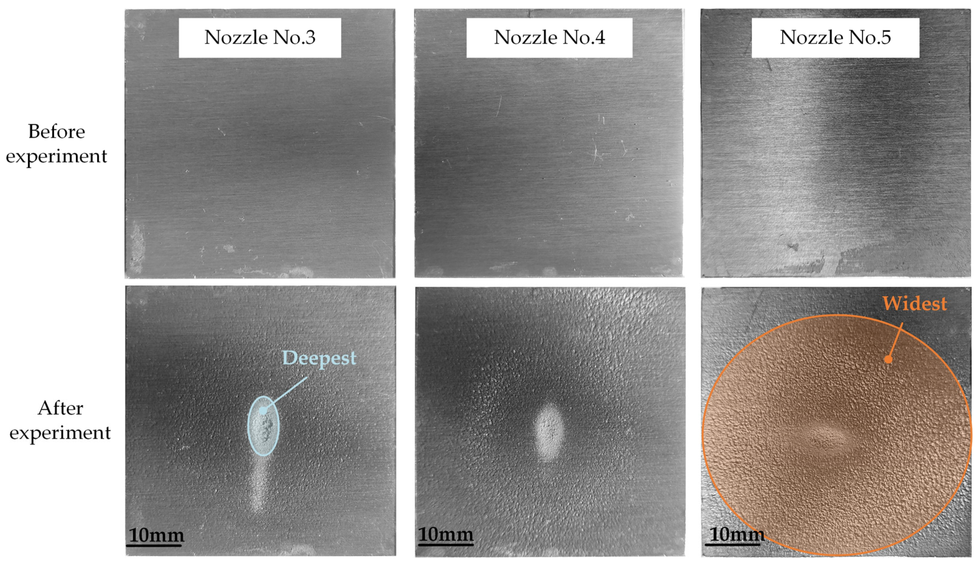
3.2. Experimental Results and Analysis
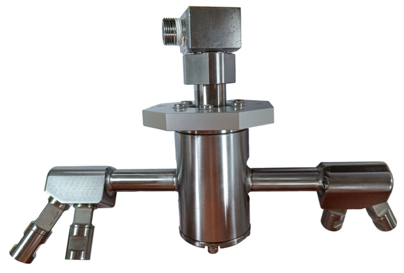
4. Design and Experiment of Self-Rotating Cleaning Device
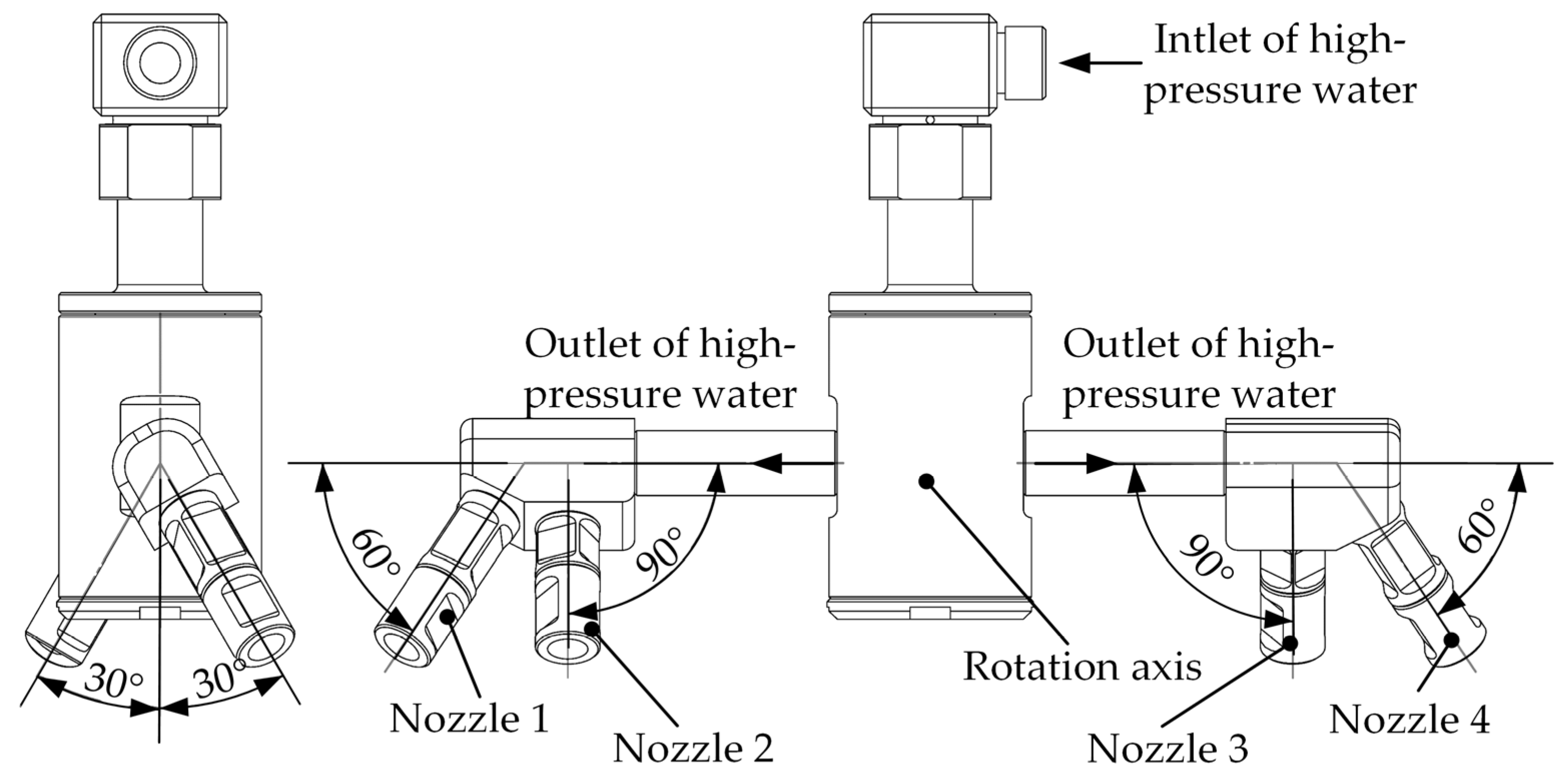
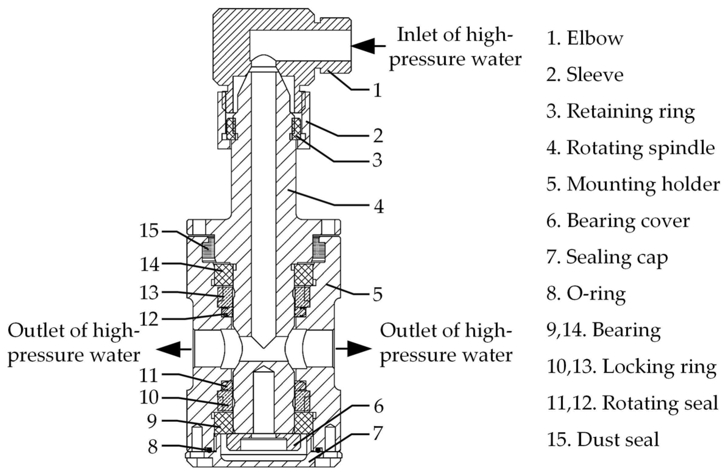
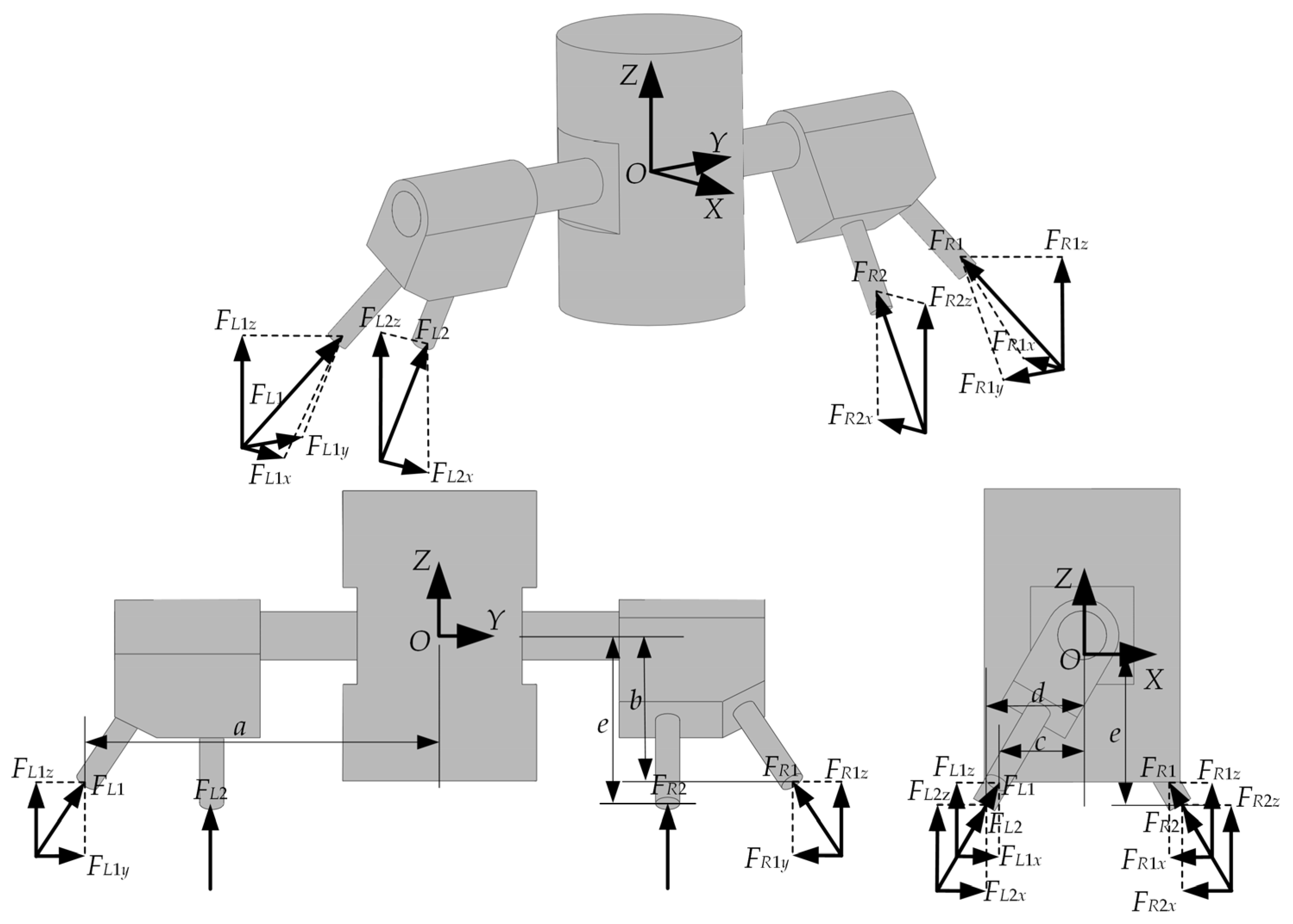
4.1. Cleaning Device Design
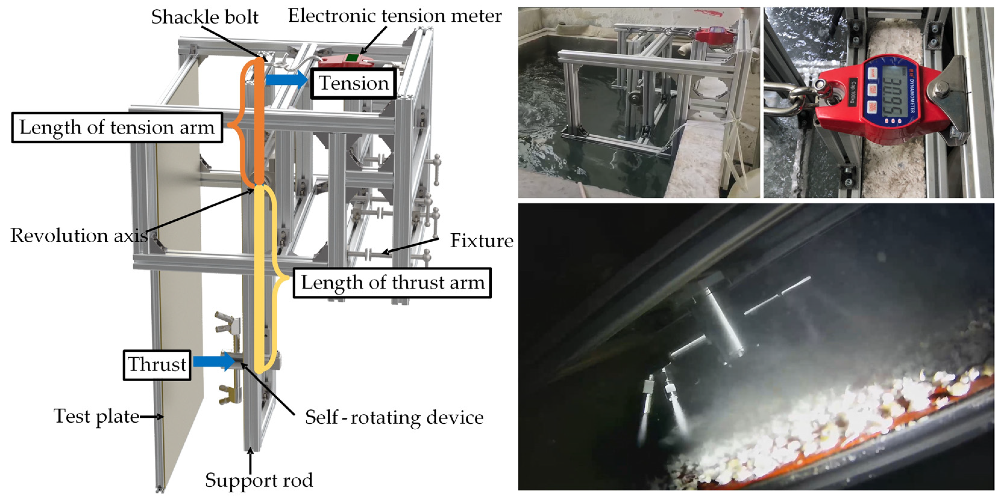
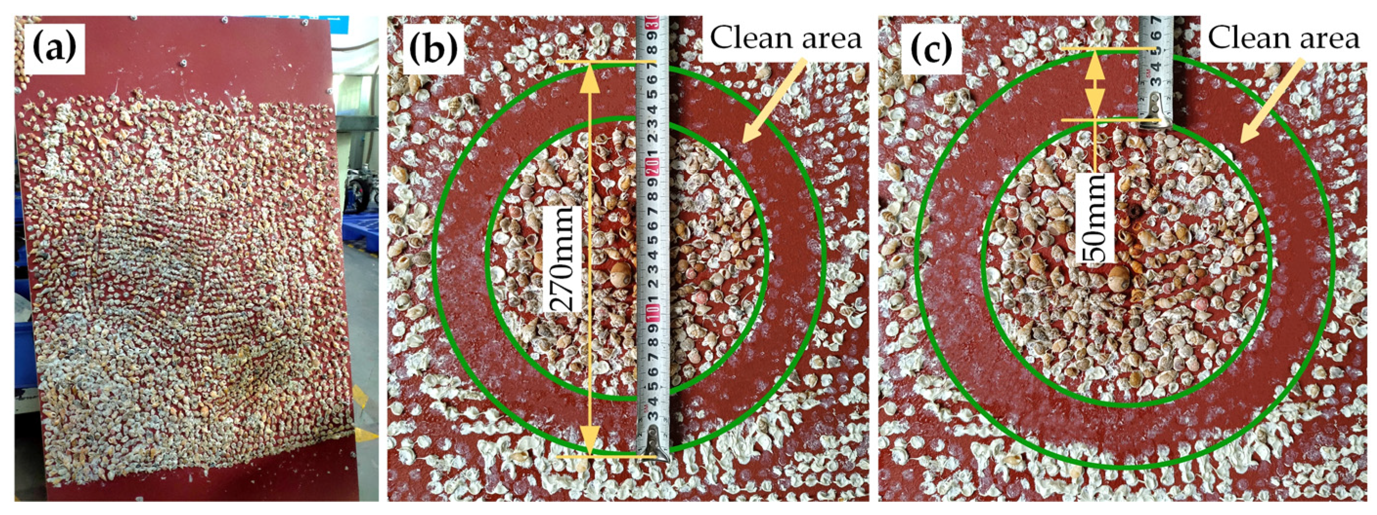
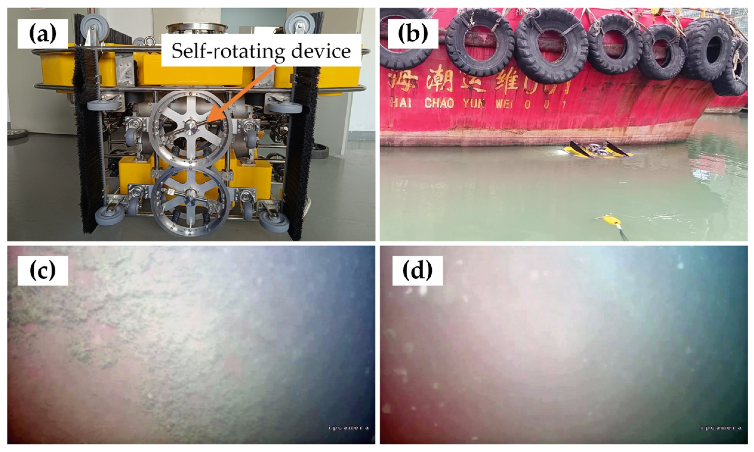
4.2. Self-Rotating Device Test and Result Analysis
5. Conclusions
Author Contributions
Funding
Institutional Review Board Statement
Informed Consent Statement
Data Availability Statement
Conflicts of Interest
References
- Yebra, D.M.; Kiil, S.; Dam-Johansen, K. Antifouling Technology—Past, Present and Future Steps towards Efficient and Environmentally Friendly Antifouling Coatings. Prog. Org. Coat. 2004, 50, 75–104. [Google Scholar] [CrossRef]
- Demirel, Y.K.; Turan, O.; Incecik, A. Predicting the Effect of Biofouling on Ship Resistance Using CFD. Appl. Ocean. Res. 2017, 62, 100–118. [Google Scholar] [CrossRef]
- Hellio, C.; Yebra, D. Advances in Marine Antifouling Coatings and Technologies; Elsevier: Amsterdam, The Netherlands, 2009. [Google Scholar]
- Davidson, I.; Scianni, C.; Hewitt, C.; Everett, R.; Holm, E.; Tamburri, M.; Ruiz, G. Mini-Review: Assessing the Drivers of Ship Biofouling Management—Aligning Industry and Biosecurity Goals. Biofouling 2016, 32, 411–428. [Google Scholar] [CrossRef] [PubMed]
- Keller, R.P.; Geist, J.; Jeschke, J.M.; Kühn, I. Invasive Species in Europe: Ecology, Status, and Policy. Environ. Sci. Eur. 2011, 23, 23. [Google Scholar] [CrossRef]
- Saebi, M.; Xu, J.; Grey, E.K.; Lodge, D.M.; Corbett, J.J.; Chawla, N. Higher-Order Patterns of Aquatic Species Spread through the Global Shipping Network. PLoS ONE 2020, 15, e0220353. [Google Scholar] [CrossRef] [PubMed]
- Duan, J.; Liu, C.; Liu, H.; Sun, J.; Zhang, Y.; Wang, N.; Zhai, X.; Guan, F.; Zheng, M.; Zhang, J.; et al. Research Progress of Biofouling and its Control Technology in Marine Underwater Facilities. Mar. Sci. 2020, 44, 162–177. (In Chinese) [Google Scholar]
- Taylor, C.J.L. The Effects of Biological Fouling Control at Coastal and Estuarine Power Stations. Mar. Pollut. Bull. 2006, 53, 30–48. [Google Scholar] [CrossRef]
- Chen, Y.; Hu, Y. Research and Application of Ship Hull Fouling Cleaning Technologies. Surf. Technol. 2017, 46, 60–71. (In Chinese) [Google Scholar]
- Kalumuck, K.; Chahine, G.; Frederick, G.; Aley, P. Development of a DYNAJET Cavitating Water Jet Cleaning Tool for Underwater Marine Fouling Removal. In Proceedings of the 9th American Waterjet Conference, Dearborn, MI, USA, 23–26 August 1997. [Google Scholar]
- Brennen, C.E. Cavitation and Bubble Dynamics; Cambridge University Press: Cambridge, UK, 2014. [Google Scholar]
- Soyama, H. Enhancing the Aggressive Intensity of a Cavitating Jet by Means of the Nozzle Outlet Geometry. J. Fluids Eng. 2011, 133, 101301. [Google Scholar] [CrossRef]
- Chen, Y.; Hu, Y.; Zhang, S. Structure Optimization of Submerged Water Jet Cavitating Nozzle with a Hybrid Algorithm. Eng. Appl. Comput. Fluid Mech. 2019, 13, 591–608. [Google Scholar] [CrossRef]
- Wu, X.-Y.; Zhang, Y.-Q.; Tan, Y.-W.; Li, G.-S.; Peng, K.-W.; Zhang, B. Flow-Visualization and Numerical Investigation on the Optimum Design of Cavitating Jet Nozzle. Pet. Sci. 2022, 19, 2284–2296. [Google Scholar] [CrossRef]
- Liu, H.; Kang, C.; Soyama, H. Experimental Study of the Influence of Test Chamber Dimensions on Aggressive Intensity of the Cavitating Jet. J. Test. Eval. 2020, 48, 3588–3601. [Google Scholar] [CrossRef]
- Li, D.; Yao, Z.; Tu, Y.; Liu, Y.; Wu, S.; Wang, X. Numerical Simulation of the Flow Field and Impact Characteristics of a Non-Submerged Dual Cavitating Waterjet. J. Vib. Shock. 2023, 42, 31–38. (In Chinese) [Google Scholar]
- Liu, B.; Gao, Y.; Ma, F. Aggressive Ability Improvement of Self-Resonating Cavitating Jets with Double-Hole Nozzle. J. Pet. Sci. Eng. 2022, 214, 110476. [Google Scholar] [CrossRef]
- Cai, T.; Chamorro, L.P.; Ma, F.; Han, J. Impact of Nozzle Lip on the Cavitation Cloud Characteristics of Self-Excited Cavitating Waterjets. Ocean. Eng. 2023, 285, 115329. [Google Scholar] [CrossRef]
- Cai, T.; Pan, Y.; Ma, F.; Xu, P. Effects of Organ-Pipe Chamber Geometry on the Frequency and Erosion Characteristics of the Self-Excited Cavitating Waterjet. Energies 2020, 13, 978. [Google Scholar] [CrossRef]
- Cai, T.; Pan, Y.; Ma, F. Effects of Nozzle Lip Geometry on the Cavitation Erosion Characteristics of Self-Excited Cavitating Waterjet. Exp. Therm. Fluid Sci. 2020, 117, 110137. [Google Scholar] [CrossRef]
- Wang, X.; Kang, Y.; Zhang, M.; Yuan, M.; Li, D. The Effects of the Downstream Contraction Ratio of Organ-Pipe Nozzle on the Pressure Oscillations of Self-Resonating Waterjets. Energies 2018, 11, 3137. [Google Scholar] [CrossRef]
- Zhang, X.; Shi, L.; Bao, C.; Sun, D.; He, Z.; Kong, L. Numerical Study on the Flow Field of Self-Propelled Multiorifices Nozzle Jetting Bit. IOP Conf. Ser. Earth Environ. Sci. 2018, 170, 022002. [Google Scholar] [CrossRef]
- Zhao, Q.; Chen, W.; Wang, L.; Chong, D.; Yan, J. Experimental Investigation on Pressure Oscillations of Steam Jet Condensation through Multi-Holes. Int. J. Heat Mass Transf. 2019, 132, 662–670. [Google Scholar] [CrossRef]
- Zhang, Y.; Feng, L.; Liu, L.; Fu, X.; Qiu, Z.; Yang, Y.; Wang, Z.; Yuan, Y.; Lu, D. Experimental Research on Double-Hole Steam Jets Dcc Heat Transfer Characteristics under Stable Condensation Pattern. Int. J. Heat Mass Transf. 2020, 158, 119881. [Google Scholar] [CrossRef]
- Wang, L.; Yue, X.; Zhao, Q.; Chong, D.; Yan, J. Numerical Investigation on the Effects of Steam and Water Parameters on Steam Jet Condensation through a Double-Hole Nozzle. Int. J. Heat Mass Transf. 2018, 126, 831–842. [Google Scholar] [CrossRef]
- Wang, L.; Chong, D.; Zhou, L.; Chen, W.; Yan, J. Numerical Simulation on Sonic Steam Jet Condensation in Subcooled Water through a Double-Hole Nozzle. Int. J. Heat Mass Transf. 2017, 115, 143–147. [Google Scholar] [CrossRef]
- Han, X.; Kang, Y.; Li, D.; Zhao, W. Effects of Surface Roughness on Self-Excited Cavitating Water Jet Intensity in the Organ-Pipe Nozzle: Numerical Simulations and Experimental Results. Mod. Phys. Lett. B 2019, 33, 1950324. [Google Scholar] [CrossRef]
- Li, D.; Kang, Y.; Wang, X.; Ding, X.; Fang, Z. Effects of Nozzle Inner Surface Roughness on the Cavitation Erosion Characteristics of High Speed Submerged Jets. Exp. Therm. Fluid Sci. 2016, 74, 444–452. [Google Scholar] [CrossRef]
- Hutli, E.; Nedeljkovic, M.; Bonyár, A. Cavitating Flow Characteristics, Cavity Potential and Kinetic Energy, Void Fraction and Geometrical Parameters—Analytical and Theoretical Study Validated by Experimental Investigations. Int. J. Heat Mass Transf. 2018, 117, 873–886. [Google Scholar] [CrossRef]
- Wu, X.; Zhang, Y.; Shen, K.; Zhao, S.; Li, G.; Hui, C.; Tian, S. Experimental Research on the Erosion Characteristics of Organ-Pipe Cavitating Jet for Hydrate-Bearing Sediments. Geoenergy Sci. Eng. 2023, 225, 211682. [Google Scholar] [CrossRef]
- Peng, K.; Tian, S.; Li, G.; Huang, Z.; Zhang, Z. Cavitation in Water Jet under High Ambient Pressure Conditions. Exp. Therm. Fluid Sci. 2017, 89, 9–18. [Google Scholar] [CrossRef]
- Soyama, H. Effect of Nozzle Geometry on a Standard Cavitation Erosion Test Using a Cavitating Jet. Wear 2013, 297, 895–902. [Google Scholar] [CrossRef]
- Apte, D.; Ge, M.; Coutier-Delgosha, O. Numerical Investigation of a Cavitating Nozzle for Jetting and Rock Erosion Based on Different Turbulence Models. Geoenergy Sci. Eng. 2023, 231, 212300. [Google Scholar] [CrossRef]
- Peng, K.; Tian, S.; Li, G.; Alehossein, H. Mapping Cavitation Impact Field in a Submerged Cavitating Jet. Wear 2018, 396–397, 22–33. [Google Scholar] [CrossRef]
- Li, J.; Liu, C.; Ran, Z.; Chai, B. Numerical Investigation of Unsteady Cavitating Turbulent Flows around a Three-Dimensional Hydrofoil Using Stress-Blended Eddy Simulation. Proc. Inst. Mech. Eng. Part E J. Process Mech. Eng. 2021, 235, 1971–1983. [Google Scholar] [CrossRef]
- Li, X.; Wu, Q.; Miao, L.; Yak, Y.; Liu, C. Scale-Resolving Simulations and Investigations of the Flow in a Hydraulic Retarder Considering Cavitation. J. Zhejiang Univ. Sci. A 2020, 21, 817–833. [Google Scholar] [CrossRef]
- Yang, Y.; Shi, W.; Tan, L.; Li, W.; Chen, S.; Pan, B. Numerical Research of the Submerged High-Pressure Cavitation Water Jet Based on the RANS-LES Hybrid Model. Shock. Vib. 2021, 2021, 6616718. [Google Scholar] [CrossRef]
- Sezen, S.; Bal, S. Computational and Empirical Investigation of Propeller Tip Vortex Cavitation Noise. China Ocean Eng. 2020, 34, 232–244. [Google Scholar] [CrossRef]
- Köksal, Ç.S.; Usta, O.; Aktas, B.; Atlar, M.; Korkut, E. Numerical Prediction of Cavitation Erosion to Investigate the Effect of Wake on Marine Propellers. Ocean Eng. 2021, 239, 109820. [Google Scholar] [CrossRef]
- Zhu, R.; Zhu, H.; Zhang, X. Numerical Investigation about the Unsteady Behavior of a Free Submerged Cavitation Jet Using the SBES Approach. Ocean Eng. 2023, 281, 115010. [Google Scholar] [CrossRef]
- Mohammadkhani, A.; Alizadeh, M. Numerical Prediction of Hydrodynamic Cavitating Flow Structures and Their Corresponding Erosion. J. Hydrodyn. 2021, 33, 546–571. [Google Scholar] [CrossRef]
- Xu, M.; Cheng, H.; Ji, B. RANS Simulation of Unsteady Cavitation around a Clark-Y Hydrofoil with the Assistance of Machine Learning. Ocean Eng. 2021, 231, 109058. [Google Scholar] [CrossRef]
- Zhang, F.; Wei, Y.; Xu, Y.; He, K. Effects of Structural Parameters of Helmholtz Nozzle on Cavitating Jet Characteristics. J. Integr. Technol. 2021, 10, 75–84. (In Chinese) [Google Scholar]
- Xing, K.; Shi, M.; Luo, X. Design of Incinerator Critical Parts for Exhaust Gas/Liquid Waste with Multiple Components. Chem. Eng. Mach. 2021, 48, 935–938. (In Chinese) [Google Scholar]
- Angelino, M.; Di Venuta, I.; Boghi, A.; Petracci, I.; Gori, F. Further Results on the Mean Mass Transfer and Fluid Flow in a Turbulent Round Jet. Int. Commun. Heat Mass Transf. 2023, 141, 106568. [Google Scholar] [CrossRef]
- Boghi, A.; Di Venuta, I.; Gori, F. Passive Scalar Diffusion in the near Field Region of Turbulent Rectangular Submerged Free Jets. Int. J. Heat Mass Transf. 2017, 112, 1017–1031. [Google Scholar] [CrossRef]
- Di Venuta, I.; Petracci, I.; Angelino, M.; Boghi, A.; Gori, F. Numerical Simulation of Mass Transfer and Fluid Flow Evolution of a Rectangular Free Jet of Air. Int. J. Heat Mass Transf. 2018, 117, 235–251. [Google Scholar] [CrossRef]
- El Hassan, M.; Bukharin, N.; Al-Kouz, W.; Zhang, J.-W.; Li, W.-F. A Review on the Erosion Mechanism in Cavitating Jets and Their Industrial Applications. Appl. Sci. 2021, 11, 3166. [Google Scholar] [CrossRef]
- Leu, M.C.; Meng, P.; Geskin, E.S.; Tismeneskiy, L. Mathematical Modeling and Experimental Verification of Stationary Waterjet Cleaning Process. J. Manuf. Sci. Eng. 1998, 120, 571–579. [Google Scholar] [CrossRef]
- Shi, H.; Kang, Y.; Li, D.; Fang, Z. Effects of the Exit Aspect Ratio of Organ-Pipe Nozzle on the Axial Pressure Oscillation Characteristics of Self-Resonating Waterjet. Proc. Inst. Mech. Eng. Part C J. Mech. Eng. Sci. 2020, 234, 4589–4598. [Google Scholar] [CrossRef]


| Nozzle Number | Structure Type | Outlet Shape | Profile |
|---|---|---|---|
| 1 | Shear nozzle with a pre-shrinking segment | Cone |  |
| 2 | Shear nozzle with a pre-shrinking segment | Cone | 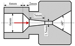 |
| 3 | Shear nozzle with a pre-shrinking segment | Conical outlet with expand cylinder segment |  |
| 4 | Shear nozzle with no pre-shrinking segment | Conical outlet with expand cylinder segment | 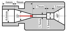 |
| 5 | Shear nozzle with no pre-shrinking segment | Spherical outlet with expand cylinder | 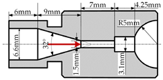 |
| 6 | Self-resonance pulsed nozzle Helmholtz type | / | 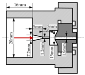 |
| 7 | Self-resonance pulsed nozzle organ pipe type | / |  |
| Grid Element Size [mm] | Pressure Drop [Pa] | Error [%] |
|---|---|---|
| 0.1 | 30,000,010.409 | 0 |
| 0.07 | 29,985,590.485 | −0.0481 |
| 0.05 | 29,998,177.102 | −0.0061 |
| Nozzle Number | Initial Mass [g] | Final Mass [g] | Mass Loss [mg] |
|---|---|---|---|
| 1 | 60.8800 | 60.8666 | 13.4 |
| 2 | 63.6957 | 63.6782 | 17.5 |
| 3 | 64.9366 | 64.8898 | 46.8 |
| 4 | 63.1979 | 63.1706 | 27.3 |
| 5 | 63.2803 | 63.2600 | 20.3 |
| 6 | 62.2402 | 62.2386 | 1.6 |
| 7 | 66.5985 | 66.5869 | 11.6 |
| Nozzle Number | Initial Mass [g] | Final Mass [g] | Mass Loss [mg] |
|---|---|---|---|
| 3 | 62.5468 | 62.5261 | 20.7 |
| 4 | 63.1108 | 63.0954 | 15.4 |
| 5 | 64.4566 | 64.4234 | 33.2 |
Disclaimer/Publisher’s Note: The statements, opinions and data contained in all publications are solely those of the individual author(s) and contributor(s) and not of MDPI and/or the editor(s). MDPI and/or the editor(s) disclaim responsibility for any injury to people or property resulting from any ideas, methods, instructions or products referred to in the content. |
© 2024 by the authors. Licensee MDPI, Basel, Switzerland. This article is an open access article distributed under the terms and conditions of the Creative Commons Attribution (CC BY) license (https://creativecommons.org/licenses/by/4.0/).
Share and Cite
Huang, S.; Huang, J.; He, K. Research on Erosion Effect of Various Submerged Cavitating Jet Nozzles and Design of Self-Rotating Cleaning Device. Appl. Sci. 2024, 14, 1433. https://doi.org/10.3390/app14041433
Huang S, Huang J, He K. Research on Erosion Effect of Various Submerged Cavitating Jet Nozzles and Design of Self-Rotating Cleaning Device. Applied Sciences. 2024; 14(4):1433. https://doi.org/10.3390/app14041433
Chicago/Turabian StyleHuang, Siwen, Jiangping Huang, and Kai He. 2024. "Research on Erosion Effect of Various Submerged Cavitating Jet Nozzles and Design of Self-Rotating Cleaning Device" Applied Sciences 14, no. 4: 1433. https://doi.org/10.3390/app14041433
APA StyleHuang, S., Huang, J., & He, K. (2024). Research on Erosion Effect of Various Submerged Cavitating Jet Nozzles and Design of Self-Rotating Cleaning Device. Applied Sciences, 14(4), 1433. https://doi.org/10.3390/app14041433