Abstract
The three-body tethered satellite system is a new potential technology for the purposes of orbital transportation. In contrast to conventional orbit transfer methods, this system is expected to transport space supplies to a predetermined orbital altitude without consuming fuel; however, the unwanted libration resulting from the Coriolis force acting on moving subsatellites may induce tumbling within the system. In order to analyze the strongly coupled characteristics of the libration motion and the variable-length tethers, a six-DOF dynamic model of the system based on Newton’s law is established. By utilizing the dynamic equations and stability criterion for linear systems, three equilibrium configurations of the satellite system with two constant-length tethers are given. The coupling characteristics of the libration angles are analyzed based on mechanical features and simulations. The results demonstrate that part of the libration energy can transfer from out-of-plane motion to in-plane motion during out-of-plane libration, but not vice versa or when in-plane libration occurs alone. Furthermore, the dynamic characteristic of this system with a predesigned deployment strategy is surveyed. This investigation reveals that such a strategy can rapidly suppress the out-of-plane libration motion while maintaining purely sinusoidal oscillations in the in-plane motion.
1. Introduction
Since Tsiolkovsky proposed the concept of a tethered satellite system (TSS) in 1895 [1], it has been extended to address many interesting space issues, such as artificial gravity, space debris removal, orbit transfer, and so on. The focus on TSSs has increased due to space missions that have been undertaken to verify this concept. For instance, the Young Engineers’ Satellite 2 (YES2) was carried out by Delta-Utec, and the Tethered Satellite System-1R (TSS-1R) was developed by NASA and the Italian Space Agency (ASI) [2,3]. Furthermore, numerous previous works [4,5,6,7,8,9] have addressed the dynamic analysis and control of TSSs.
These successful space missions inspire researchers to explore the dynamic modeling, analysis, and control of multitethered satellite formations, which are made up of numerous satellites connected by space tethers [4,10,11]. One of the multitethered satellite formations is the three-body tethered satellite system (TB-TSS), which has potential applications in mission scenarios like high atmospheric observations and space transportation [4,10,11,12]. A TB-TSS is generally formed by one main satellite and two subsatellites connected by tethers, where the main satellite can transport the two subsatellites to the desired position by deploying and retrieving the tether without thrusters [13]. During both the deployment and retrieval phases, one difficulty associated with the TB-TSS is the libration motion of the subsatellites (or climber) caused by the Coriolis force due to their movement [14,15]. Research shows that the movement that occurs may lead to the tumbling of the whole system [16]. Thus, the dynamic characteristics analysis of such systems when deploying, station-keeping, and transporting the climber is pivotal for a successful operation.
Due to the fact that the dynamic characteristics of the TB-TSS play a critical role in the process of the successful completion of a scheduled mission, a lot of research has been devoted to investigating the complex dynamics and control of this system in recent years. Based on the assumption of a rigid tether, Misra et al. [17] examined the dynamics of a double-pendulum TB-TSS for the cases of fixed-length and variable-length tethers. Because of its simplicity and adaptable accuracy, the classical two-piece dumbbell model (TPDM) proposed in Ref. [17] is frequently utilized to investigate the dynamic responses and control of TB-TSS. Woo and Misra [18] further studied the libration frequencies and moving effects of climbers in a TB-TSS. Jung et al. [19] analyzed the dynamic responses of a tethered satellite system while the middle body was moving along the tether. In addition, the same authors surveyed the dynamic characteristics of a TB-TSS during the deployment and retrieval phases [20]. For the TB-TSS with moving subsatellites, Kojima et al. [21] used Kane’s method to derive the system dynamics equations. An active force is required to drive the middle subsatellite to suppress the potential wobble of the tether. In order to investigate the libration motion of a partial space elevator with a climber moving at a constant speed in a circular orbit, Shi, Zhu, and Zhu [22] established the convenient nonlinear dynamics of a TB-TSS. The dynamics of a TB-TSS were investigated and analyzed by taking into account the effects of the climber’s climbing velocity, the mass ratio of the climber over the end body, and the end body’s deployment and retrieval. Furthermore, for various climbing speeds, a parametric dynamic analysis of the TB-TSS that transfers the middle subsatellite from the lower orbit to the upper orbit at a constant speed was performed in Ref. [13]. Some works further studied the unstable dynamic characteristics of a TB-TSS in an elliptic orbit. Kojima et al. [23] presented the chaotic motion of a TB-TSS in an elliptic orbit. Shi et al. [24] investigated the oscillation motion of a TB-TSS with constant-length tethers in a large elliptic orbit. The stability of a TB-TSS, with a fixed-length tether and in-plane/out-of-plane motion in elliptic and inclined orbits, was analyzed by the monodromy matrix derived by the Floquet theory [25]. In order to understand the influence of the flexible characteristics of a tether on swing angles, Li and Zhu [26] presented a high-fidelity and high-accuracy dynamic model of a TB-TSS. In addition, a flexible-tether model of a TB-TSS using an absolute nodal coordinate formulation was set up to examine the dynamic influence caused by the distributed mass and elasticity of the tether in [27]. Although the modeling and dynamic analysis of TB-TSSs have been extensively researched, the existing literature mentioned above is based on the assumption that the out-of-plane motion is nonexistent [16,19,21,22] or that the system is station-keeping [4,23,24]. To the best knowledge of the authors, there have been few published works that analyze the out-of-plane dynamics of a TB-TSS with the deployment or retrieval phases occurring in three dimensions; however, the out-of-plane response is inevitably caused by the Coriolis force when deploying or retrieving a space tether. Therefore, it is still necessary to establish a TB-TSS dynamic model considering libration motion and variable-length tethers in three dimensions. Moreover, analyzing the strongly coupled dynamic characteristics, especially the influence of out-of-plane motion on the dynamic response of a TB-TSS, is still challenging.
In order to describe a three-dimensional space dynamic model of a TB-TSS and analyze the coupling dynamic characteristics of the system, a six-DOF dynamic equation of the system based on Newton’s law was established. The proposed dynamic model is an extension of the existing TB-TSS dynamic model, which accounts for three-dimensional deployment/retrieval dynamics variation as well as in-plane and out-of-plane dynamics behavior. With the proposed model, it is easy to derive the explicit physical meaning of each equation and reveal the physical coupling properties between the degrees of freedom. Furthermore, compared to the Lagrange method, the proposed method avoids the complicated decoupling process and facilitates dynamic analysis. To analyze the influence of out-of-plane motion on the dynamic response of the TB-TSS, the equilibrium configuration and coupling characteristics of libration angles with fixed-length tethers are studied using mechanical features and simulation. Additionally, the dynamic effect of out-of-plane motion on the TB-TSS with variable-length tethers is studied using a predesigned deployment strategy.
The paper is organized as follows: in Section 2, a novel dynamic model that has simple and explicit physical significance is modeled using a two-piece dumbbell model, and dynamic equations are derived by applying Newton’s law. Additionally, we analyze and discuss the equilibrium and coupling characteristics of the libration angles. In Section 3, we investigate the dynamic performance of the TB-TSS and analyze the simulation results. Finally, Section 4 concludes the presented work.
2. Mathematical Model
2.1. System Description and Basic Assumptions
Figure 1 illustrates the three-dimensional configuration of the TB-TSS. The structure comprises a main satellite and two subsatellites connected by two straight, massless, and inextensible tethers, L1 and L2. Before constructing the dynamic model, several reasonable assumptions were made with reference to [22]. Since the mass of the main satellite is significantly greater than the combined mass of the two subsatellites, the mass center of the system was assumed to be located at the main satellite and the system was assumed to be traveling in a Keplerian orbit. The inextensible and massless rod model used for the tether is always tensioned in the following sections and the satellite’s mass is much greater than the tether’s. Consequently, the three satellites are treated as lumped mass points due to the significant length of the tether. It is important to note that, in mathematical models, the central gravitational field plays a dominant role. All external perturbations, such as solar radiation pressure and atmospheric drag force, are neglected.
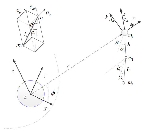
Figure 1.
Schematic of the three-body tethered satellite system.
Generalized coordinates were defined to develop the dynamic model of the system. Figure 1 illustrates the introduction of the Earth’s inertial coordinate system, denoted as E-XYZ, with its origin situated at the center of the Earth. Additionally, the EZ-axis aligns with the Earth’s rotation axis and points toward the north, the EX-axis points to the vernal equinox, and the EY-axis completes the right-hand coordinate system. The local vertical local horizontal (LVLH) frame, represented by o-xyz, is a rotating frame. Its origin is located at the mass center of the main satellite. The ox-axis extends radially outward from the Earth along the local vertical, the oy-axis represents the direction of the local horizontal, and the oz-axis is determined by the right-hand rule. Two tethered coordinate systems (o-xiyizi (i = 1, 2)) are utilized, with their origins at the mass center of the main satellite and subsatellite 1, respectively; oxi points in the direction of satellite i + 1 and rotates θi (in-plane angle of each tether) around the oz-axis of orbit coordinate oxyz. Then, it rotates αi (out-of-plane angle of each tether) around the oy-axis to obtain the tether coordinate system.
We assume that the mass center of the system resides in a circular orbit, with the position of the main satellite determined by the radial coordinate r and the true anomaly . Tether L1 connects the main satellite (m0) to the subsatellite (m1), with θ1 representing the in-plane rotation of the tether and α1 its out-of-plane rotation. Similarly, tether L2 connects satellite m1 to satellite m2, where θ2 represents the in-plane rotation of the tether and α2 its out-of-plane rotation.
2.2. Dynamic Model of TB-TSS
In this subsection, we develop an advanced three-dimensional dynamic model of TB-TSS, specifically focusing on describing the libration motion of the tether during deployment or retrieval. The system is represented using a two-piece dumbbell model, neglecting the lateral and transversal vibrations caused by the tether’s flexibility. The two-piece dumbbell model is divided into two components in order to derive the dynamic equation. The schematic diagram in Figure 2 illustrates the connection between the main satellite (m0) and the subsatellite (m1) via tether L1. To formulate the equations of motion for this section using Newton’s law, vector l1 is introduced, which represents the displacement from m0 to m1 and has a magnitude of −l1. Thus, the position of tether L1 can be expressed in inertial coordinates as:
where vectors r0 and r1 represent the position of main satellite m0 and subsatellite m1, respectively. The orbit angular velocity ω1 of tether L1 in the tether coordinate system, relative to the Earth-centered inertial coordinate system, is given by:
where Ay denotes the rotation matrix of the oy-axis relative to the inertial coordinate system (described in Appendix A); and represent the in-plane and out-of-plane angular velocity of tether L1; is the angular velocity of the orbit; is the gravitational constant of Earth. The second derivative of Equation (1) with respect to time is obtained as follows:
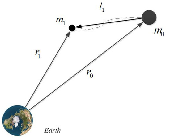
Figure 2.
Schematic diagram of tether 1.
The dynamic equations of tether L1 in the inertial coordinate frame is then derived by Newton’s law:
where and are the tension vectors acting on mass m0 and m1, respectively, and and denote the gravitational force vectors acting on mass m0 and m1, respectively. and can be written as:
Furthermore, by expanding Equation (5) using the Taylor formula, and retaining only the first-order terms, we obtain:
Since vector Equation (4) is formulated in the tether coordinate system, the forces must be transformed from the inertial coordinate to the tether coordinate frame. The following transformations are employed:
By substituting Equations (3) and (6)–(8) into Equation (4), after a set of complex but routine algebraic manipulations, we obtain the dynamic equations of tether L1:
Similarly, the dynamic equations of tether L2 can be derived as:
A detailed derivation of the model can be found in Appendix B. The dynamic model of the TB-TSS is described by Equations (9)–(14), and was established based on Newton’s laws. We can easily derive the explicit physical significance of each equation: (1) The tether acceleration primarily consists of centripetal acceleration in the tether direction (first term), gravitational acceleration in the tether direction (second term), and tether tension acceleration (third term). (2) The in-plane angular acceleration primarily comprises the components of gravitational acceleration in the in-plane angular direction (first term), Coriolis acceleration (second term), and tether tension acceleration (third term). (3) The out-of-plane angular acceleration of the plane mainly consists of Coriolis acceleration (first term), centripetal acceleration (second term), gravitational acceleration in the out-of-plane angular direction of the plane (third term), and tether tension acceleration (fourth term). Based on the above equations, it can be concluded that the libration motion of the TB-TSS is influenced by the tether tension, which differs from the dynamic characteristics of a tethered satellite in the one-piece dumbbell model. Specifically, the libration motion of tether L1 is affected by the tension of tether L2, while the libration motion of tether L2 is influenced by the tension of tether L1. In contrast, the libration motion of a tethered satellite in the one-piece dumbbell model is not affected by tension [28]. Additionally, the dynamic equations are presented in the form of state-space equations, which facilitate dynamic analysis and the design of control laws. Specifically, controlling tension of tether T2 can suppress the in-plane roll and out-of-plane pitch motion of tether L1. Similarly, controlling the tension of tether T1 suppresses the in-plane roll and out-of-plane pitch motion of tether L2.
2.3. Equilibrium Points and Coupling Characteristic of Libration Angles
To analyze the coupling characteristics of libration motion in the dynamic response of the TB-TSS, reasonable simplifications and assumptions are made in order to inspect the natural motion of the system dynamics. In the simplified model, the length of the tether in the system is constant, which corresponds to the state-keeping phase. Thus, the dynamic characteristics of the system do not consider the influence of variable-length tethers, but only the coupling libration motion. In this case, the length of tethers does not change, which means . Dynamic Equations (9)–(14) can be simplified by using variables , and the results can be represented as follows:
where and can be solved by the follow equations:
In this case, the length of the tether is fixed and the Coriolis acceleration is zero. According to the principle of gravity gradient force on subsatellites increasing as the orbital radius decreases [3], the gravitational acceleration on subsatellites increases as the length of the tethers increases. The effect of the gravity gradient will cause the system to stabilize along the local vertical, and centripetal acceleration will speed up the whole system. Thus, it is necessary to study how to arrive at equilibrium and how the coupling libration motion influences the dynamic characteristics of the TB-TSS with fixed-length tethers.
2.3.1. Equilibrium Points
In this subsection, we examine the equilibrium configurations of TB-TSS. At the equilibrium point, the state variables with respect to time are all equal to zero. Considering the effect of the gravity gradient, the subsatellites are defined as collinear. To identify the equilibrium point equation of the system, variables , , , , , , , and are set to zero and , are set in Equations (15)–(18). After some calculation, we obtain:
where and denote the equilibrium solutions for and , respectively. The equilibrium points are solved by Equations (21)–(24) as:
Three kinds of equilibrium configurations can be acquired, and they are shown in Figure 3. The equilibrium configurations are parallel to the x-axis, y-axis, and z-axis of the LVLH frame. To study the stability of the equilibrium points, we can substitute the equilibrium points into the linearized Equations (15)–(18) to calculate the eigenvalues and determine the stability [29]. According to linear system theory, eigenvalues are stable if they are negative and unstable if they are regular. Considering small oscillations around the equilibrium points, it is easy to obtain that the configuration shown in Figure 3a is stable and those in Figure 3b,c are unstable.
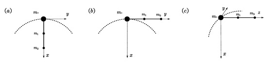
Figure 3.
Equilibrium configurations: (a) parallel to x-axis; (b) parallel to y-axis; (c) parallel to z-axis.
2.3.2. Coupling Characteristic of Libration Angles
The dynamic coupling characteristic of libration angles was investigated using Equations (15)–(18), as described in this section. Here, the changes in tether length were ignored, and the focus was solely on the angular coupling. Two distinct cases were considered in order to analyze and discuss the mechanical characteristics of libration motion.
Case 1: This case assumes there is no initial in-plane roll motion and studies the effect of out-of-plane pitch motion on in-plane roll motion. The in-plane libration angles and velocities are defined as , and Equations (15)–(18) can be simplified as:
Equations (27) and (30) indicate that, in this scenario, the acceleration of the in-plane angle is influenced by the Coriolis acceleration generated by the relative motion of the in-plane and out-of-plane angles. Additionally, the velocity of the in-plane angle is affected by the motion of the out-of-plane angle. Energy transfer between in-plane and out-of-plane angular motion occurs via centripetal angular acceleration, expressed as . In more detail, in this case, we assume that the initial out-of-plane angles are any nonzero angles, and the effect of the gravity gradient causes the subsatellites to be “pulled” to the position along the local vertical. This effect causes out-of-plane motion to occur and produces out-of-plane angular velocity. Thus, Equations (27) and (29) are nonzero for and lead to in-plane motion. Finally, the transfer of energy from out-of-plane motion to in-plane motion is realized.
Case 2: In this case, the dynamic characteristics of in-plane roll motion are analyzed by assuming there is no initial out-of-plane motion. The out-of-plane libration angles and velocities are defined as , and Equations (15)–(18) can be simplified as:
Equations (32) and (34) demonstrate that the out-of-plane angular acceleration is constantly zero in this situation. The in-plane motion is solely influenced by gravitational and tensional acceleration, with no coupling relationship with out-of-plane motion. Accordingly, the out-of-plane motion does not receive any energy injection; as a result, the out-of-plane libration angles remain constant at all times, as given by . These conclusions are also verified in the simulation in Section 3.2. Furthermore, in both cases, tension is not the main factor affecting the energy transfer between in-plane and out-of-plane motion, although there is tension in libration motion. Particularly when out-of-plane motion is absent, the tension does not cause out-of-plane motion but still has a tangible impact on in-plane motion.
3. Simulation Results and Discussion
3.1. Validation of Equations
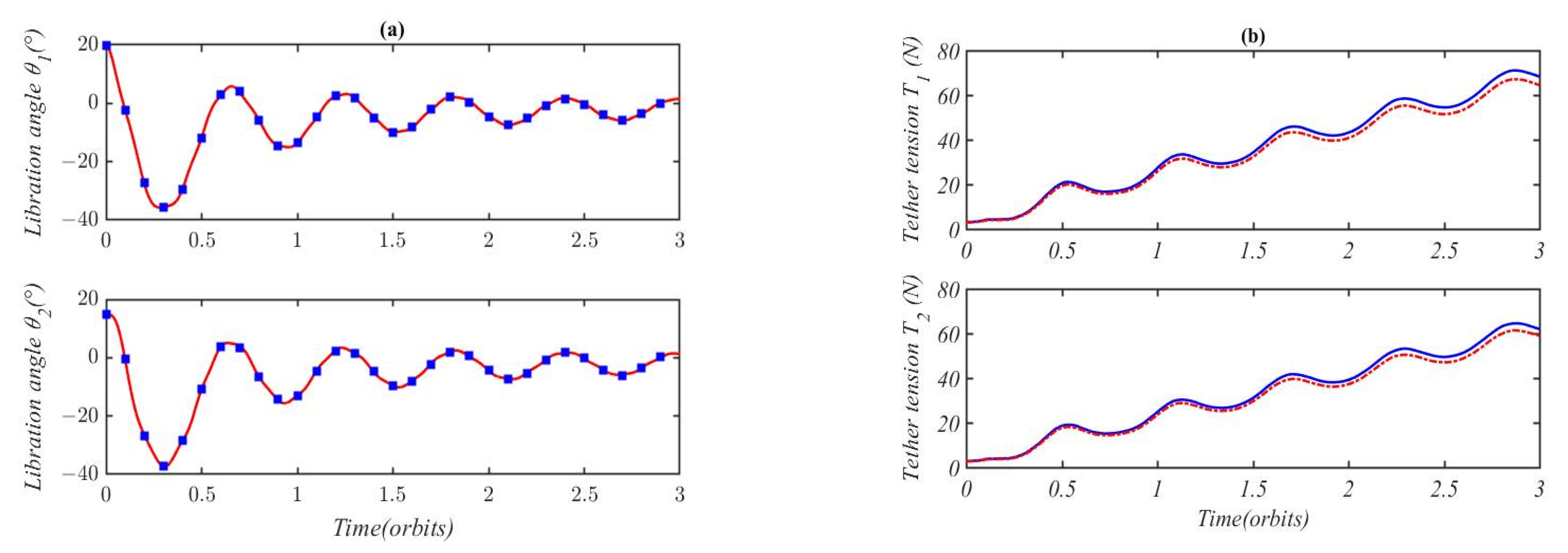
In order to verify the validity of the dynamic equations obtained in this study, their dynamic characteristics in this study and those in [22] were tested under the same conditions. In [22], the out-of-plane motion is ignored in the model, thus the out-of-plane motion should be neglected in Equations (9)–(14). Substituting the out-of-plane libration angles into Equations (9)–(14), we have four degrees of freedom, and the corresponding generalized coordinates are and . Therefore, the same physical model is achieved. The equations of motion were verified by comparing the dynamic responses calculated in this study with the model responses reported by Shi et al. [22] with the same initial conditions and physical parameters. To facilitate the comparison, the initial conditions and relevant physical parameters of the system were set uniformly. The initial conditions were set as , , , and , which were randomly selected within reasonable limits. In order to reflect the movement of the tether, the tether velocity was set to . The physical parameters of the system were the same as those in [22]: orbit radius set at , mass of main satellite , mass of subsatellites set at , . The simulations were solved in a circular orbit in MATLAB 2017b with ODE45, an RK4 numerical integrator with variable step size.
Figure 4a shows the numerical results of the libration angles in the present study and in [22] when the deploying velocity of tethers is 1 m/s. The libration angles calculated in this study (indicated by squares) are in good agreement with those in [22], as depicted in Figure 4a. Figure 4b shows the tether tension in the present study (dotted line) and [22] (solid line). The numerical results indicate that the tether tension in [22] was slightly higher compared to the present study. From Equations (10) and (13), the tether tension comprises Coriolis, in-plane roll, and gravitational acceleration, which are the same as the results in [22]. In this simulation, the Coriolis and in-plane roll acceleration in [22] and this study are the same. So, the difference arises from the variation in gravitational force truncation during the approximation process. In this study, only the first-order terms were retained when expanding the gravitational force using the Taylor series. It can be concluded that an accurate dynamic model of gravity helps in accurately estimating tether tension.
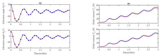
Figure 4.
Comparison of libration motion and tether tension when the tether deploying velocity is 1 m/s: (a) libration motion in present study (squares) and [22] (solid line); (b) tether tension in present study (dotted line) and [22] (solid line).
3.2. Dynamic Behavior of TB-TSS with Fixed-Length Tethers
In this section, we consider a fully deployed two-piece dumbbell TB-TSS model with a constant tether length. The libration characteristics of the TB-TSS are investigated by taking four degrees of freedom. Specifically, dynamic Equations (15)–(18) describe the nonlinear model of the TB-TSS with fixed-length tethers, while Equations (19) and (20) are utilized to solve the tether tension. The numerical simulation of the libration characteristics of the TB-TSS with fixed-length tethers was performed using the MATLAB ODE45 solver. The physical parameters of the system were the same as those in [22]. The orbital altitude of the main satellite was . The mass of the three satellites was , , and . The two fixed-length tethers were set at . To investigate the dynamic behavior of this system, five cases of initial attitude were set, and the relevant initial angles and their specific values are listed in Table 1. The initial attitude angles were set to ignore the initial out-of-plane pitch angles, as in case 1, and gradually change to only the initial pitch angles. Cases 5 and 4 were set as the controls to study the effect of initial attitude on system dynamic characteristics. In order to avoid the impact of the initial angular velocity on the system characteristics, other initial variables were given as zero: .

Table 1.
Five test cases for initial attitude angles and their specific values.
Figure 5 shows the dynamic responses of the TB-TSS with fixed length following initial attitude angles , . In this case, the initial in-plane angles are equal to 20° and the initial out-of-plane angles are zero, indicating the absence of initial disturbance in the out-of-plane direction. In Figure 5a, the lines for and overlap, resembling a cosine function graph, while the line for is zero. Meanwhile, Figure 5b shows three zero lines representing libration angles , , and , indicating that the initial in-plane angles do not affect the out-of-plane motion when the TB-TSS is fully deployed. Additionally, Figure 5c shows the tether tension of the two tethers, with slightly higher tension for L1 than L2 due to the gravitational effect of subsatellite 2. Furthermore, by comparing Figure 5a,c, it is observed that the period of in-plane roll motion is equal to the period of tension change. The maximum tension occurs when the in-plane libration angles pass through zero, implying that the two tethers are aligned along the local vertical. Combining the trends from both figures, it is evident that the tension changes rapidly from peak to bottom as the libration angle changes from zero to its maximum value, while tension exhibits only slight variation as the libration angle changes from the maximum to the minimum point. As shown in Equations (19) and (20), tension is related to centripetal acceleration, which is relevant to when . Consequently, tether tension decreases with decreasing roll angular velocity when it corresponds to the orbital angular velocity. When the roll angular velocity is opposite the orbital angular velocity, the tension remains small as the two angular velocities almost cancel each other out.
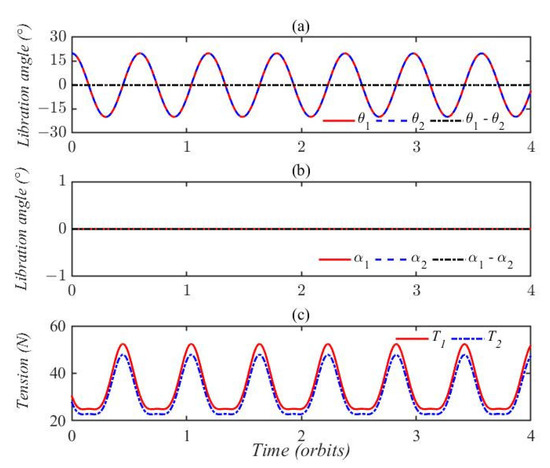
Figure 5.
Dynamic characteristics of TB-TSS with fixed-length tether in case 1; (a) libration angles of θ1, θ2 and θ1 − θ2; (b) libration angles of α1, α2 and α1 − α2; (c) tether tension of tethers L1 and L2.
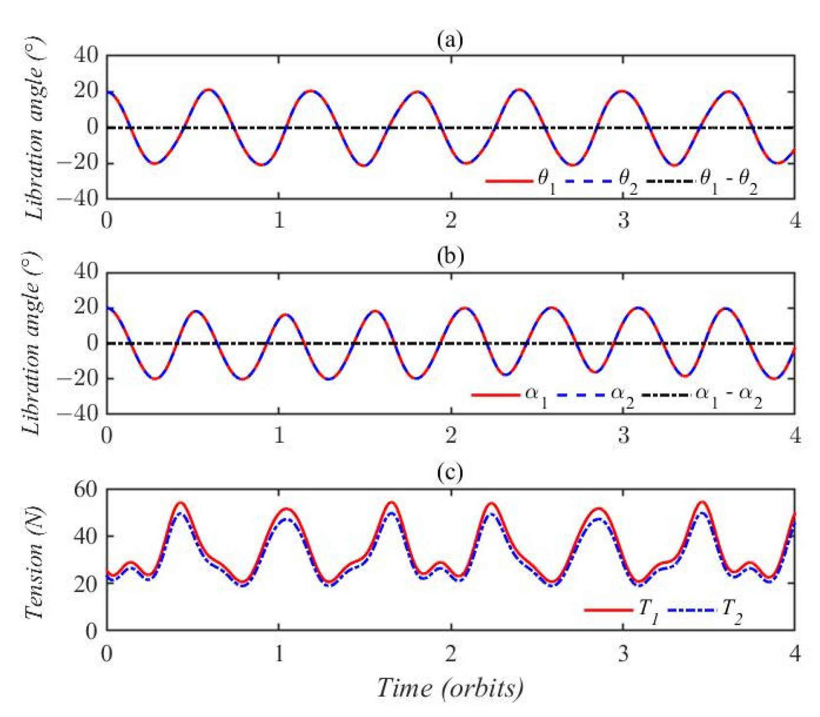
In case 2, the initial attitude angles were set as , indicating that the initial in-plane and out-of-plane angles were equal and the two tethers were collinear. Figure 6a shows the dynamic response of in-plane libration angles and , and it can be seen that the two curves oscillate periodically and overlap. The out-of-plane pitch motions are illustrated in Figure 6b, where it can be seen that the motions of pitch angles and are identical. The tension in this case is depicted in Figure 6c, where it can be seen that tension T1 is larger than tension T2 and the two curves exhibit quasiperiodic variation. The amplitude of tension in Figure 6c is almost equal to the maximum value of tension in Figure 5c, despite the addition of out-of-plane pitch motion.
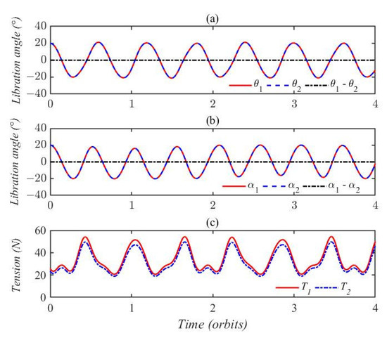
Figure 6.
Dynamic characteristics of TB-TSS with fixed-length tether in case 2; (a) libration angles of θ1, θ2 and θ1 − θ2; (b) libration angles of α1, α2 and α1 − α2; (c) tether tension of tethers L1 and L2.
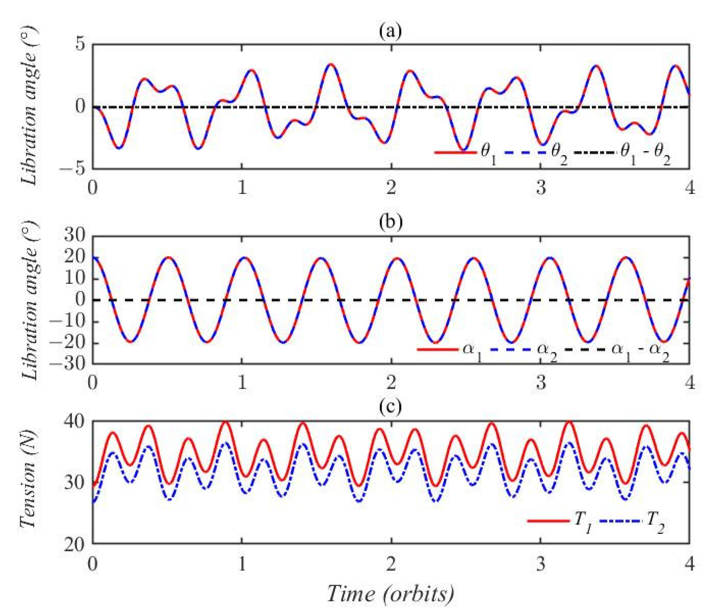
Figure 7 presents the dynamic characteristics of the TB-TSS with fixed-length tethers in case 3. In this simulation, the initial attitude angles were set as , . As seen in Figure 7a,b, the oscillations of libration angles do not exhibit a purely cosine variation; instead, they show quasiperiodic oscillation. Unlike in Figure 5 and Figure 6, here the oscillations of the two in-plane and two out-of-plane angles do not overlap and do not have higher frequencies. In this case, the oscillation amplitude of and is larger than the initial attitude angles, while the oscillation amplitude of and never exceeds 20°. As shown in Figure 7a, the maximum value of is nearly 60°, which is greater than the initial difference of 40°. This indicates that the initial attitude angles may increase the response amplitude of roll angles. The maximum value of roll angles is nearly 30°, and the increase is nearly half of the initial roll angles. This also suggests that libration energy can be delivered from out-of-plane to in-plane. Figure 7c shows that tether tension T1 and T2 almost overlap each other, although the amplitude of T1 is slightly larger than T2. Moreover, the peak value of each tether tension occurs when the libration angle changes from zero to the maximum (or minimum) value. Comparing with Figure 5c and Figure 6c, it can be observed that, in this case, the peak values of tether tension are significantly higher than in the previous two cases. This indicates a close relationship between peak tether tension and initial libration angle.
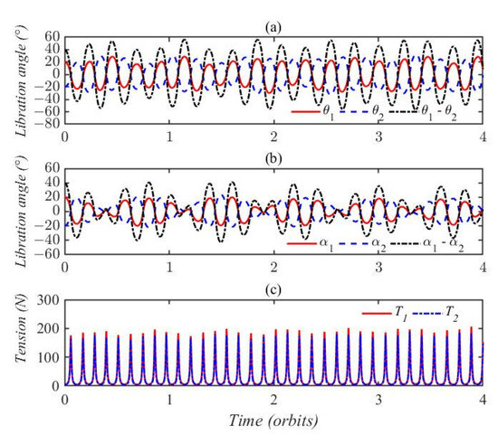
Figure 7.
Dynamic characteristics of TB-TSS with fixed-length tethers in case 3; (a) libration angles of θ1, θ2 and θ1 − θ2; (b) libration angles of α1, α2 and α1 − α2; (c) tether tension of tethers L1 and L2.
Figure 8 displays the libration responses and tether tensions in case 4, where the initial attitude angles were determined as , . As shown in Figure 8a,b, the in-plane and out-of-plane libration motion overlap each other. Moreover, the out-of-plane motion oscillates sinusoidally, while the in-plane motion exhibits random oscillation. A comparison of Figure 8 with Figure 5 leads to a definitive conclusion: libration energy can be transferred from out-of-plane motion to in-plane motion, but not vice versa. In case 4, the amplitudes of tether tension in Figure 8c are smaller than those in the previous cases. This phenomenon occurs because the dominant centripetal acceleration is located in the orbit plane.
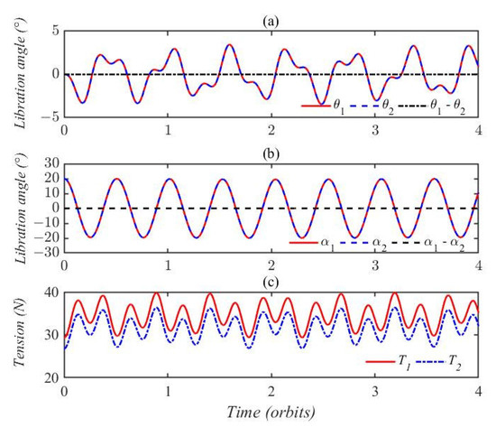
Figure 8.
Dynamic characteristics of TB-TSS with fixed length tethers in case 4; (a) libration angles of θ1, θ2 and θ1 − θ22; (b) libration angles of α1, α2 and α1 − α2; (c) tether tension of tethers L1 and L2.
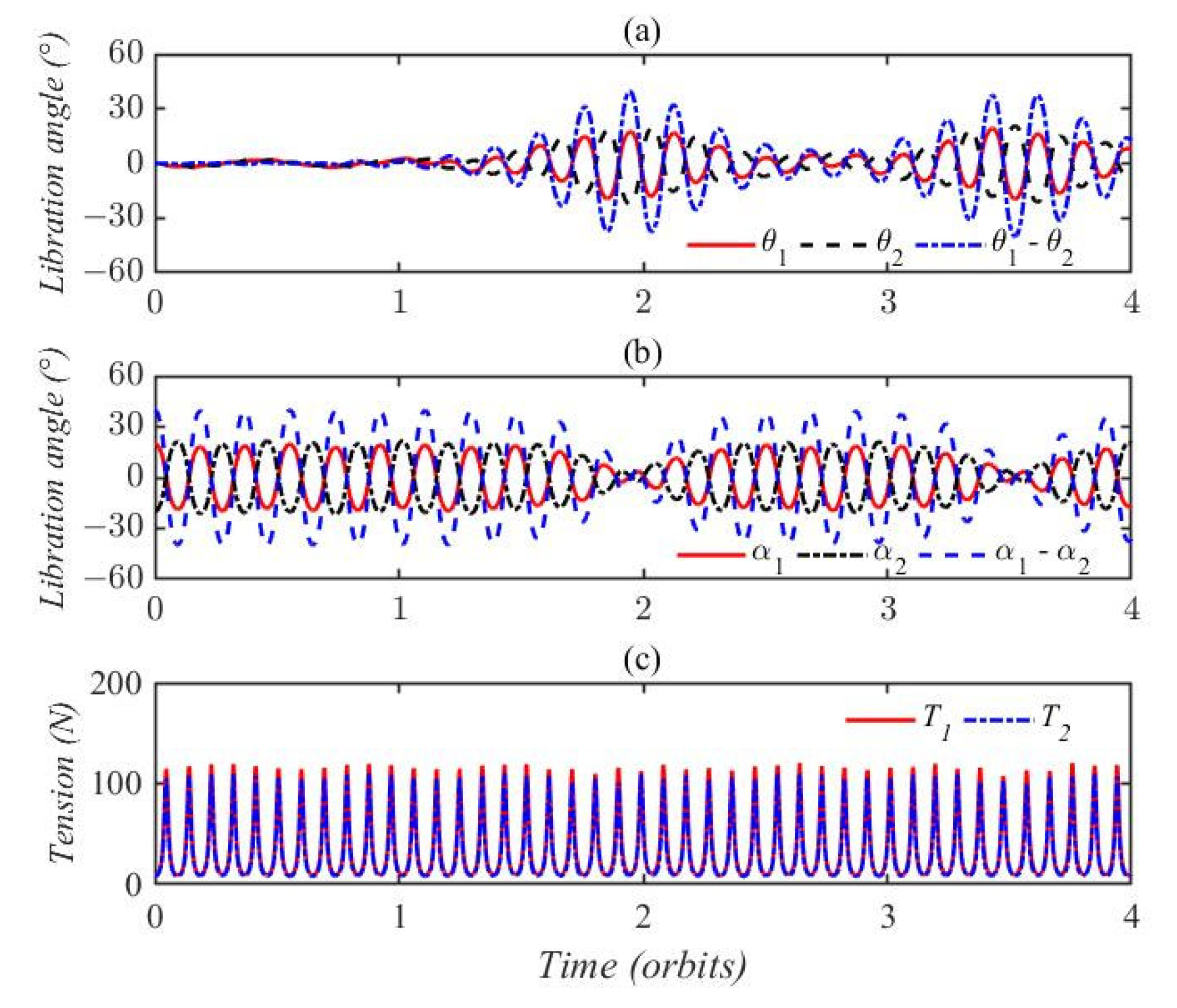
Finally, a set of initial attitude angles was chosen: , , and . In this case, the oscillation amplitudes of and were lower after one orbit, while the oscillation responses of and were enhanced, as shown in Figure 9a,b. Additionally, the in-plane oscillation becomes atrophic, while the out-of-plane oscillation begins to strengthen after two orbits. This observation aligns with the findings in Figure 8a,b. The tether tension in this case is depicted in Figure 9c. The maximum values of T1 and T2 are larger compared to those in case 4; however, the values remain below those in case 3. These results suggest that the tension characteristics are influenced by the initial attitude angles, and the amplitudes of tether tension elongate with different initial libration angles. The maximum tether tension in case 5 is nearly three times the value in case 4. Consequently, it can be concluded that the initial attitude angles significantly influence the dynamic characteristics of a fully deployed TB-TSS.
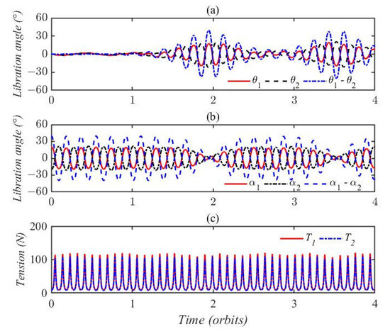
Figure 9.
Dynamic characteristics of TB-TSS with fixed-length tether in case 5; (a) libration angles of θ1, θ2 and θ1 − θ2. (b) libration angles of α1, α2 and α1 − α2. (c) tether tension of tethers L1 and L2.
In conclusion, the simulation results show that the initial attitude angles significantly influence the dynamic characteristics of a fully deployed TB-TSS. The peak value of tether tension is closely related to the initial attitude angles. Moreover, the amplitude is greater with different initial attitude angles than with the same initial attitude angles. Libration energy is not transferred from in-plane motion to out-of-plane motion when only in-plane libration occurs, while energy can be delivered from out-of-plane motion to in-plane motion when out-of-plane libration occurs, and energy transfer will reach dynamic equilibrium after a period of time.
3.3. Deployment Strategy
Smooth deployment of the tether is the key to TB-TSS operation. However, due to the Coriolis force induced by the relative motion of libration and the motion of tether deployment, it is not easy to quickly and stably deploy the tether at the expected length. Therefore, an effective deployment strategy is important to achieving stable and rapid deployment of the TB-TSS. A common open-loop deployment strategy is to control the tether length rate [26,30]. Because of its simplicity, it is widely used to verify the deployment dynamics of tethered satellite systems. There are two common tether length-rate control laws: uniform speed development and exponential development. In the actual development process, the deployment speed of the uniform speed control strategy will change abruptly in the initial and end stages of tether deployment, which will result in rebounding and even winding of the tether. The exponential deployment strategy will increase infinitely or approach zero with time. There is a risk of tether entanglement occurring when the speed of the tether is up to 20 m/s [22]. In addition, the exponential deployment speed should approach zero when the deployment task is complete. Therefore, the development dynamics of the TB-TSS are surveyed with a predesigned deployment strategy in this section.
Since a TB-TSS can be deployed with the gravity gradient or tension, the state of the system may be far from the ideal target goals and objectives in the final phase. The deployment phase is an unstable process; the deployment task can only be completed without any slack or winding of the tether [22]. This means that libration motion is inevitable, and the tension should always be positive to keep the tether straight. A deployment strategy needs to be designed to ensure that the tension is positive and the libration angle does not exceed 90°. The results in the existing literature show that a too fast deployment speed and sudden changes in the tether speed will lead to system instability. Therefore, a predesigned deployment strategy was developed. The deployment strategy involves predesigning a constrained piecewise function that regulates the deployed velocity as three phases. During the initial phase, the deployment velocity accelerates exponentially from rest to cruise velocity. In the second phase, the deployment velocity maintains this state. Finally, in the last phase, the deployment velocity is restrained exponentially to rest as it reaches the desired length. The specific form is given as follows:
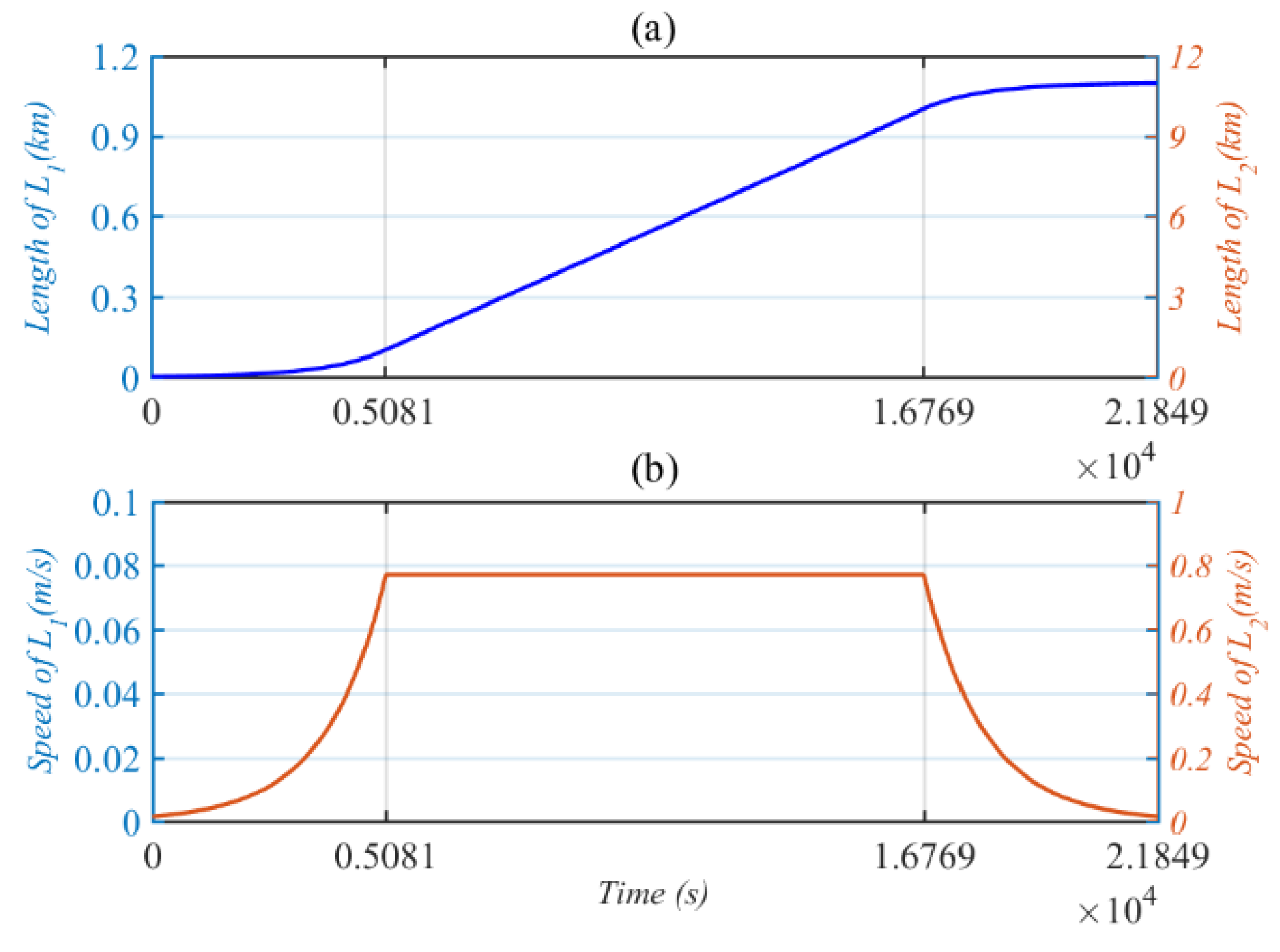
where the arguments of deployed acceleration of two tethers is designed as , , and ; and are the values of constantly deploying speeds in the second phase; and represent the deployed acceleration of two tethers in the final phase. According to the total deployed tether length and deployed velocity, timing , , and can be computed as , , and . These parameters are designed according to the simulation requirement that the maximum deployment velocity is insufficient to cause system instability and reaches the desired length when the deployment velocity converges to zero in the final phase. The methods of applying two tether lengths and deploying velocity are plotted in Figure 10.
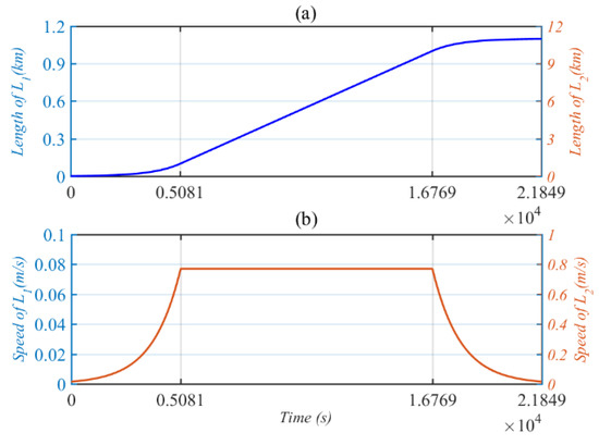
Figure 10.
Predesigned motion of two tethers. (a) Deployed tether length. (b) Deployed velocity.
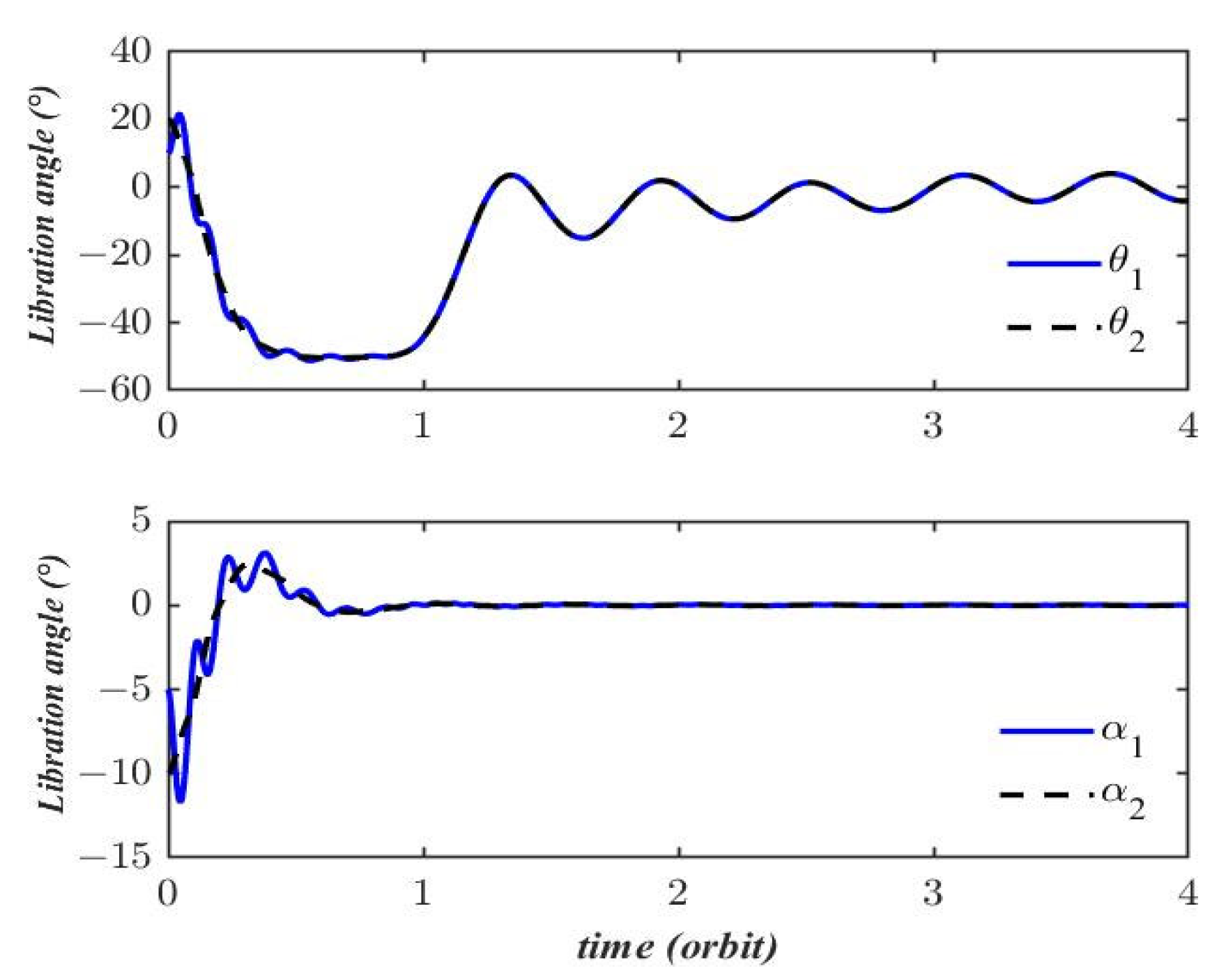
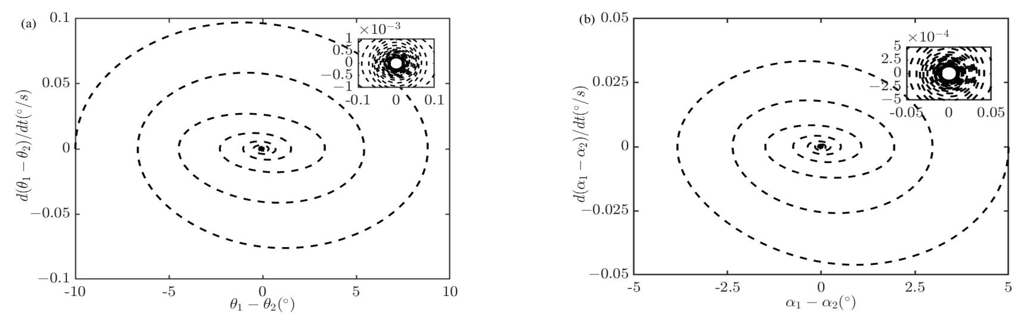
To investigate the effect of this deployment strategy, we performed a simulation with the predesigned motion. It should be noted that the specified deployment rate is assumed to be driven solely by tension, and the tension can be obtained with Equations (9) and (12). The system parameters are chosen as , , , and , which are from [22]. The initial attitude variables are , , , and , which are selected randomly. In order to ensure that the initial attitude is static, the initial angular velocities of attitude are set as . Figure 11 displays the time histories of the libration motions obtained with the deployment strategy. It shows that the predesigned deployment strategy effectively eliminates the out-of-plane libration motion after almost one orbit, while the in-plane libration motion exhibits a purely sinusoidal variation that persists even after the completion of deployment. To further analyze the libration motion, the phase diagrams of θ1 − θ2 and α1 − α2 are presented in Figure 12. The phase diagrams reveal that the differences in in-plane θ1 and θ2, as well as α1 and α2, tend to be very small limit cycles. Combined with the results of Figure 11 and Figure 12, it can be concluded that the deployment strategy can effectively and stably complete the task, the libration motion in the whole process is no more than 90°, and instability will not occur after deployment.
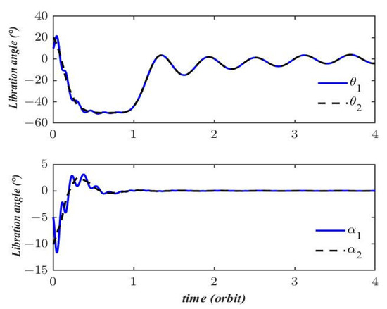
Figure 11.
Libration motion of two tethers.
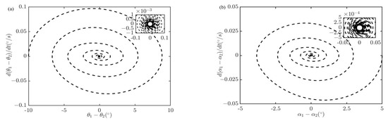
Figure 12.
(a) Phase diagram of θ1 − θ2. (b) Phase diagram of α1 − α2.
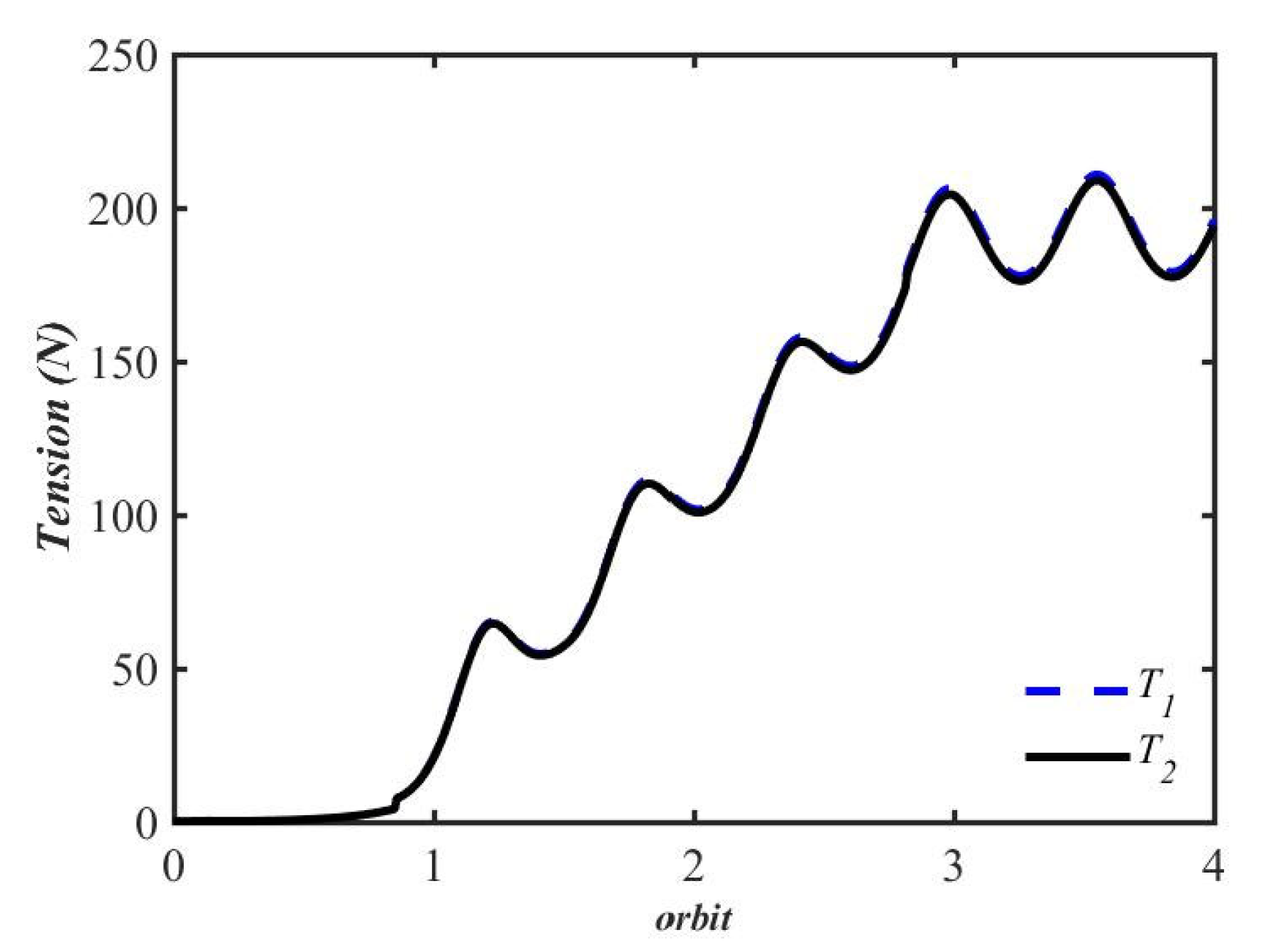
Figure 13 presents the time history of the tension in two tethers. It can be observed that the tension in both tethers increases over the first three orbital periods and subsequently fluctuates periodically around constant values, exhibiting a very small amplitude. Therefore, it can be inferred that the libration angles attain a stable state once the deployment is complete. An important aspect that deserves attention is that the tension values in both tethers remain non-negative integers throughout the entire process, indicating the absence of slackness. In summary, the simulation results demonstrate that the predesigned deployment strategy is suitable for suppressing libration during the development of the TB-TSS and ensures that both in-plane and out-of-plane motions maintain stable limit cycles. Furthermore, although the speed of the two tethers is different, the oscillation characteristics and dynamic performance of their tension remain virtually identical.
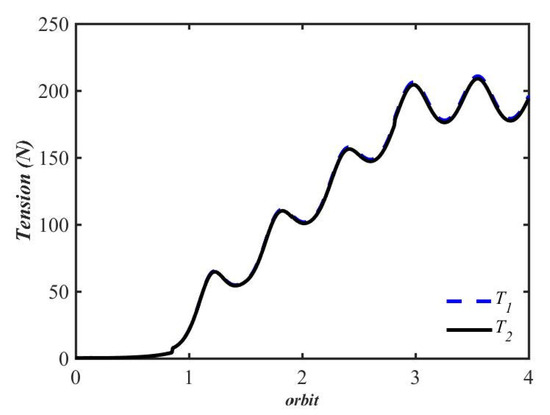
Figure 13.
Tension of two tethers.
4. Conclusions
In this paper, a two-piece dumbbell mathematical model with deployment/retrieval is developed based on Newton’s law. The proposed model extends the existing dynamic models by incorporating out-of-plane roll motion and in-plane pitch motion with deployment for a TB-TSS. The dynamic characteristics of the TB-TSS under both fixed and varying tether lengths due to release are investigated. Additionally, a deployment strategy is proposed to suppress the libration motion during deployment. Numerical simulations are conducted to examine the influence of various conditions on the system’s dynamics. The simulation results yield several important conclusions, as follows:
(1) Three equilibrium configurations can be acquired for the fixed-length tethers of a TB-TSS in circular orbit. One configuration is stable, with both tethers aligned along the local vertical direction of the Earth. The other two configurations are unstable, parallel to the y-axis and z-axis of the LVLH frame.
(2) For a fully deployed TB-TSS, the simulation results indicate a close relationship between the peak value of tether tension and the initial attitude angles. Furthermore, the simulation shows that libration energy can be delivered from out-of-plane motion to in-plane motion when out-of-plane libration occurs, while libration energy does not transfer from in-plane to out-of-plane when only in-plane libration occurs.
(3) The predesigned deployment strategy for length-rate control can suppress the libration of the system in the process of effective deployment. Furthermore, the out-of-plane motion rapidly converges to zero, while the in-plane motion retains a purely sinusoidal oscillation.
In summary, the coupling dynamic responses of the TB-TSS are analyzed and discussed with a six-DOF dynamic model. The results have practical applications for guiding the deployment and suppressing the libration of a TB-TSS in circular orbit, as well as for designing stability controllers. However, it is assumed that the system follows a planar circular orbit and ignores the influence of external space perturbations, such as solar radiation pressure, atmospheric drag, and J2 perturbation. The dynamic characteristics of the TB-TSS can be further discussed for some complex practical scenarios, such as considering the influence of the orbital motion of the main satellite and external space perturbations. In addition, the proposed deployment strategy is an open-loop strategy, which may produce unstable output and cause mission failure. An improved closed-loop control scheme could be further designed to guarantee the robustness and control performance of the TB-TSS.
Author Contributions
Conceptualization, T.H. and Z.Z.; methodology, T.H.; software, T.H.; validation, T.H. and Z.Z.; formal analysis, T.H.; investigation, T.H.; resources, Z.Z.; data curation, T.H.; writing—original draft preparation, T.H.; writing—review and editing, T.H. and Z.Z.; visualization, T.H.; supervision, Z.Z.; project administration, Z.Z.; funding acquisition, Z.Z. All authors have read and agreed to the published version of the manuscript.
Funding
This research received no external funding.
Institutional Review Board Statement
Not applicable.
Informed Consent Statement
Not applicable.
Data Availability Statement
Data are contained within the article.
Conflicts of Interest
The authors declare no conflicts of interest.
Appendix A
Rotation Matrix
In three-dimensional Euclidean space, one coordinate system can reach another coordinate system through some rotations; this process is called coordinate transformation. The rotation of a coordinate system about one of its axes leads to a new coordinate system, and this process is called primitive rotation. In this paper, if the tether coordinate system is rotated by angles about the Y-axis to form a new frame in the inertial coordinate system, the rotation can be represented by a matrix, which is called the rotation matrix . The mathematical expression of is
Similarly, if the tether coordinate system is rotated by angles around the Z-axis, its rotation matrix is
Primitive rotation is the simplest coordinate rotation, and the transformation between general coordinate systems can always be achieved by three primitive rotations (in this paper, by the above two primitive rotations). To achieve the rotation from the tether coordinate system to the inertial coordinate system, first the tether coordinate system rotates angles around the zi-axis to become the transition frame , and then rotates angles around the yi-axis to become the inertial coordinate system.
Appendix B
Dynamic Model of Tether L2
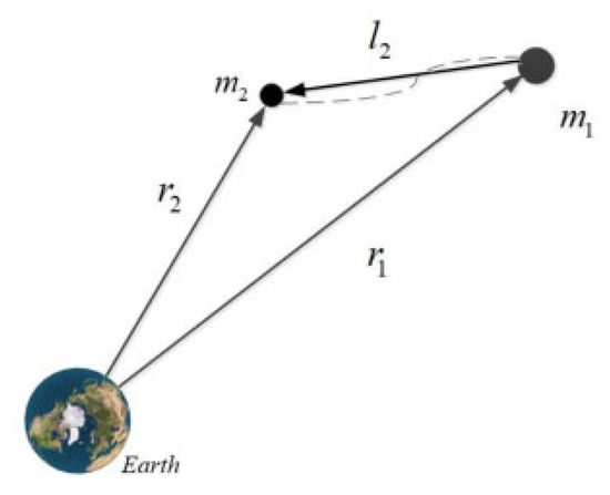
Figure A1.
Schematic diagram of tether 2.
Figure A1.
Schematic diagram of tether 2.

Similar to the section dynamic model of the TB-TSS, a vector l2 is defined and the size of it is −l2. The position of the tether L2 is,
The angular velocity ω2 of tether L2 in the tether coordinate system relative to the inertial coordinate system can be expressed as
Substituting Equation (A4) into Equation (A3), and requesting the second derivative of Equation (A3) with respect to time, one obtains
The motion equations of the tether L2 can be equated to
Just like tether L1, some transformations are used to gain the motion of tether L2
Substituting Equations (A5), (A7) and (A8) into Equation (A6), we obtain equations for angle θ2, angle α2, and l2 that describe the pitch motion, the roll motion, and the change in tether 2 in the orbital plane as Equations (12)–(14).
References
- Pearson, J. The real history of the space elevator. In Proceedings of the 57th International Astronautical Congress, Valencia, Spain, 2–6 October 2006. [Google Scholar]
- Aslanov, V.S.; Ledkov, A. Dynamics of Tethered Satellite Systems; Elsevier: Cambridge, UK, 2012. [Google Scholar]
- Wen, H.; Jin, D.P.; Hu, H.Y. Advances in dynamics and control of tethered satellite systems. Acta Mech. Sin. 2008, 24, 229–241. [Google Scholar] [CrossRef]
- Misra, A.K.; Modi, V.J. Three-dimensional dynamics and control of tether-connected N-body systems. Acta Astronaut. 1992, 26, 77–84. [Google Scholar] [CrossRef]
- Williams, P. Deployment/retrieval optimization for flexible Tethered satellite systems. Nonlinear Dynam. 2008, 52, 159–179. [Google Scholar] [CrossRef]
- Pang, Z.; Jin, D.P.; Yu, B.; Wen, H. Nonlinear normal modes of a tethered satellite system of two degrees of freedom under internal resonances. Nonlinear Dynam. 2016, 85, 1779–1789. [Google Scholar] [CrossRef]
- Yu, B.S.; Jin, D.P. Deployment and retrieval of tethered satellite system under J2 perturbation and heating effect. Acta Astronaut. 2010, 67, 845–853. [Google Scholar] [CrossRef]
- Wen, H.; Jin, D.P.; Hu, H.Y. Three-dimensional deployment of electro-dynamic tether via tension and current control with constraints. Acta Astronaut. 2016, 129, 253–259. [Google Scholar] [CrossRef]
- Sun, G.H.; Zhu, Z.H. Fractional order tension control for stable and fast tethered satellite retrieval. Acta Astronaut. 2014, 104, 304–312. [Google Scholar] [CrossRef]
- Lorenzini, E.C. A three-mass tethered system for micro-g/variable-g applications. J. Guid. Contr. Dynam. 1987, 10, 242–249. [Google Scholar] [CrossRef]
- Lorenzini, E.C.; Cosmo, M.; Vetrella, S.; Moccia, A. Dynamics and control of the tether elevator/crawler system. J. Guid. Contr. Dynam. 1989, 12, 404–411. [Google Scholar] [CrossRef]
- Shi, G.F.; Zhu, Z.H.; Li, G.Q. A novel looped space tether transportation system with multiple climbers for high efficiency. Acta Astronaut. 2021, 179, 253–265. [Google Scholar]
- He, T.; Zhu, Z.X.; Luo, J.J. Stable cargo transportation for underactuated partial space elevator with model uncertainties and disturbances. Adv. Space Res. 2024, 73, 1936–1951. [Google Scholar] [CrossRef]
- Shi, G.F.; Zhu, Z.H.; Li, G.Q. Libration suppression of partial space elevator by controlling climber attitude using reaction wheel. Acta Astronaut. 2021, 183, 126–133. [Google Scholar] [CrossRef]
- Shi, G.F.; Zhu, Z.H.; Li, G.Q. Stable cargo transportation of partial space elevator with multiple actuators. Adv. Space Res. 2021, 68, 2999–3011. [Google Scholar] [CrossRef]
- Ishikawa, Y.; Otsuka, K.; Yamagiwa, Y.; Doi, H. Effects of ascending and descending climbers on space elevator cable dynamics. Acta Astronaut. 2018, 145, 165–173. [Google Scholar] [CrossRef]
- Misra, A.K.; Amier, Z.; Modi, V.J. Attitude dynamics of three-body tethered systems. Acta Astronaut. 1988, 17, 1059–1068. [Google Scholar] [CrossRef]
- Woo, P.; Misra, A.K. Dynamics of a partial space elevator with multiple climbers. Acta Astronaut. 2010, 67, 753–763. [Google Scholar] [CrossRef]
- Jung, W.; Mazzoleni, A.P.; Chung, J. Dynamic analysis of a tethered satellite system with a moving mass. Nonlinear Dynam. 2014, 75, 267–281. [Google Scholar] [CrossRef]
- Jung, W.; Mazzoleni, A.P.; Chung, J. Nonlinear dynamic analysis of a three-body tethered satellite system with deployment/retrieval. Nonlinear Dynam. 2015, 82, 1127–1144. [Google Scholar] [CrossRef]
- Kojima, H.; Fukatsu, K.; Trivailo, P.M. Mission-function control of tethered satellite/climber system. Acta Astronaut. 2015, 106, 24–32. [Google Scholar] [CrossRef]
- Shi, G.F.; Zhu, Z.X.; Zhu, Z.H. Libration suppression of tethered space system with a moving climber in circular orbit. Nonlinear Dynam. 2018, 91, 923–937. [Google Scholar] [CrossRef]
- Kojima, H.; Iwasaki, M.; Fujii, H.A.; Blanksby, C.; Trivailo, P. Nonlinear control of libration motion of tethered satellites in elliptic orbits. J. Guid. Control Dyn. 2004, 27, 229–239. [Google Scholar] [CrossRef]
- Shi, G.F.; Zhu, Z.X.; Zhu, Z.H. Dynamics and control of three-body tethered system in large elliptic orbits. Acta Astronaut. 2018, 144, 397–404. [Google Scholar] [CrossRef]
- Kojima, H.; Sugimoto, T. Stability analysis of in-plane and out-of-plane periodic motions of electrodynamic tether system in inclined elliptic orbit. Acta Astronaut. 2009, 65, 477–488. [Google Scholar] [CrossRef]
- Sun, X.; Xu, M.; Zhong, R. Dynamic analysis of the tether transportation system using absolute nodal coordinate formulation. Acta Astronaut. 2017, 139, 266–277. [Google Scholar] [CrossRef]
- Li, G.Q.; Zhu, Z.H. On libration suppression of partial space elevator with a moving climber. Nonlinear Dynam. 2019, 97, 2107–2125. [Google Scholar] [CrossRef]
- Sun, G.H.; Zhu, Z.H. Fractional-Order Tension Control Law for Deployment of Space Tether System. J. Guid. Control. Dyn. 2014, 37, 2062–2066. [Google Scholar] [CrossRef]
- Khalil, H.K. Nonlinear Systems, 3rd ed.; Prentice Hall: Upper Saddle River, NJ, USA, 2002. [Google Scholar]
- Cohen, S.S.; Misra, A.K. The effect of climber transit on the space elevator dynamics. Acta Astronaut. 2009, 64, 538–553. [Google Scholar] [CrossRef]


Disclaimer/Publisher’s Note: The statements, opinions and data contained in all publications are solely those of the individual author(s) and contributor(s) and not of MDPI and/or the editor(s). MDPI and/or the editor(s) disclaim responsibility for any injury to people or property resulting from any ideas, methods, instructions or products referred to in the content. |
© 2024 by the authors. Licensee MDPI, Basel, Switzerland. This article is an open access article distributed under the terms and conditions of the Creative Commons Attribution (CC BY) license (https://creativecommons.org/licenses/by/4.0/).