Abstract
Doubly fed induction generators (DFIG) find extensive application in variable-speed wind power plants, providing notable advantages such as cost-effectiveness, operational flexibility across varying speeds, and enhanced power quality. This research focuses on the control of DFIGs employed in variable-speed wind turbine configurations. A suitable mathematical model is chosen for representative systems following a comprehensive review of contemporary research. Subsequent analysis reveals the instability of the open-loop time response of the system. To address this instability, the initial approach involves the implementation of the conventional model predictive controller (MPC). However, the outcomes indicate that this controller falls short of delivering satisfactory performance despite the enhanced stability. In the subsequent phase, efforts are made to mitigate the impact of wind input variability by utilizing the Kalman filter, given its effectiveness in handling high variability. Following this, a novel methodology is introduced, which combines nonlinear MPC with the Lyapunov function. This method is based on the nonlinear model of the system. By using the Lyapunov function in the nonlinear MPC structure, the stability of the designed controller is guaranteed. To validate the proposed control approach, the results are compared with PID based controller in MATLAB/Simulink. The simulation results showed that the output variables of the modeled DFIG system achieve stability within a reasonable timeframe applying the input.
1. Introduction
Given the increasing demand for electrical energy and the environmental challenges associated with fossil fuels, there is a significant emphasis on utilizing clean and renewable energy sources [1,2,3]. Among various renewable energy sources, wind energy is one of the most convenient and cost-effective options, and in several countries, a significant portion of the electricity demand is met through the operation of wind power plants. Integrating these power plants into the electricity transmission and distribution network can introduce dynamic and static effects on the overall network performance. The variable speed of the wind, resulting in fluctuations in the input power of the wind turbine, can lead to variations in the frequency and voltage of the power grid [4]. Hence, it is crucial to comprehensively examine and evaluate the conditions and consequences of utilizing wind power plant capacities on the power grid. This includes investigating key aspects such as active power-frequency requirements, reactive power-voltage requirements, fault protection, power quality, and controller performance [5].
In recent years, the DFIG has emerged as a prominent component in the global wind turbine market, serving as an alternative to traditional variable speed generators [6]. A mechanical shaft system connects the wind turbine to the DFIG. This setup involves a low-speed turbine shaft connected to a high-speed generator shaft through a gearbox. The DFIG comprises a wound rotor induction generator. Its stator windings are directly connected to the grid, while the rotor windings are connected to the grid through two back-to-back AC/DC converters. [7,8,9]. The rotor side converter (RSC) and grid side converter (GSC) are voltage source converters employing pulse width modulation (PWM). This topology enables independent control of active and reactive power, and the power rating of the converters is only one-third of the turbine’s rated power, making it a cost-effective solution.
So far, many studies have been presented regarding the issue investigated in this paper, some of them are mentioned here. In ref. [10], an evaluation is conducted to compare the performance of the transfer function-based model and the state space-based model in the context of MPC design for DFIG. In ref. [11], a novel variable-step model predictive control strategy is presented with the aim of enhancing the capability of wind turbines to continue operating without disconnecting from the grid in the event of a fault. The methodology involves two key steps. Firstly, a predictive-control state-space model of a doubly fed wind farm is formulated based on its operational principles. Subsequently, model predictive control is implemented on the rotor side of the DFIG to achieve rapid tracking of the rotor current to the prescribed reference value during the low-voltage ride-through of the DFIG. In ref. [12], an updated model predictive control technique is suggested. This research aims to regulate the generator in two aspects; firstly, to closely track the reference wind speed with high precision utilizing both the rotor side and grid side converters; secondly, to mitigate system errors. The suggested approach involves the optimization of a function, incorporating current magnitude errors derived from the discrete mathematical model to predict the switching state of the converter. In ref. [13], an innovative Lyapunov-based model predictive control strategy is introduced for a multi-drive system based on a nine-switch inverter. This drive system comprises two AC motors and a singular nine-switch inverter designed to supply power to multiple induction motors. MPC is chosen as the preferred feedback strategy in AC-drive applications, owing to its rapid dynamic characteristics and its ability to effectively address multiple control objectives. In ref. [14], a cascaded fractional MPC, combined with a fractional-order PID controller, is developed to ensure an efficient response of the power system in the presence of load disruptions and variations in system parameters. The controller is fine-tuned using a Sooty Tern Optimization algorithm to identify optimal parameters. Experimental assessments involve testing the controller under scenarios involving power mixing from renewable energy sources such as PV and wind, along with varying load conditions in a multi-area hybrid power system.
Controlling a system that generates power from a non-uniform input, such as wind, poses a significant challenge. The constantly changing wind speed, influenced by factors like gusts, adds to the situation’s complexity. Efforts have been undertaken to address the wind non-uniformity issue in synchronous wind generator systems by maintaining the rotor speed close to a constant value through blade pitch control. A brushless synchronous generator with a permanent magnet is employed in certain systems, considering the wind turbine as the sole power source. Nevertheless, induction generators offer advantages over synchronous generators, including lower costs, increased reliability, and more straightforward controls. A new advancement in the control of a reactive static power source opens up the possibility of exploring the integration of an induction generator with the control of a reactive static power source as an alternative to the use of synchronous generators. This paper’s initial step involves selecting an appropriate mathematical model with detailed considerations for DFIG wind turbines. Selecting an appropriate model is crucial as the electricity generation process in wind turbines involves inherent noise and uncertainties. Therefore, an effective model should encompass these uncertainties to a significant extent. In the subsequent phases of the research, the model predictive control (MPC) controller is employed. The organization of this paper is as follows: the second section outlines the formulation of the DFIG model and describes the proposed MPC method. The third section presents the simulation results of the proposed approach. The concluding part provides an overview of the general findings of the paper.
2. Problem Formulation
2.1. Dynamic Modeling of DFIG
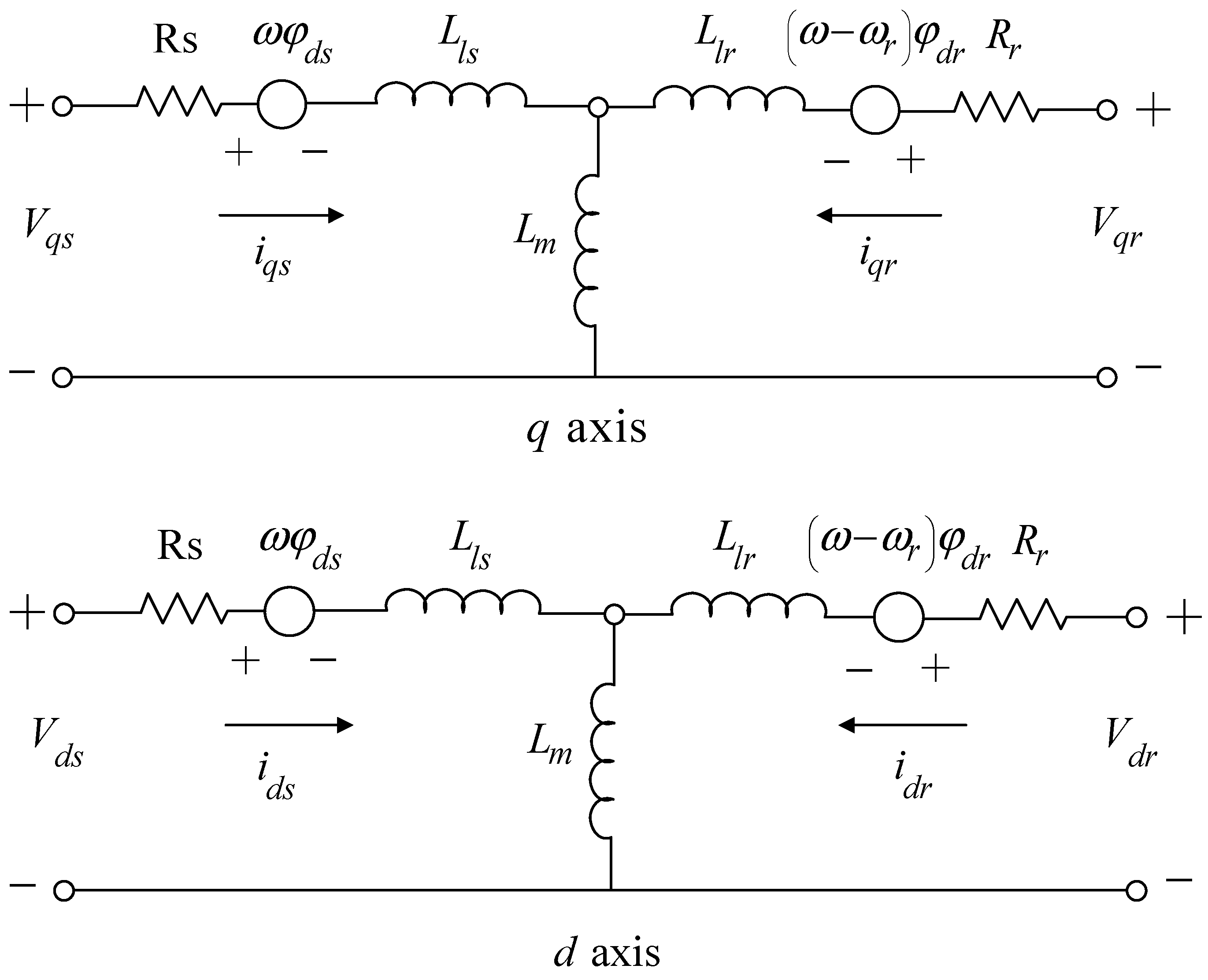
In the examination and regulation of the DFIG, the dynamic model of the induction machine is outlined within an arbitrary and rotating reference frame, denoted by the necessary angular velocity Ω, as illustrated in the equivalent circuit depicted in Figure 1 [15].

Figure 1.
Equivalent circuit of DFIG in an arbitrary reference frame [14].
The equations for the stator and rotor voltages , and , presented in the arbitrary frame of reference rotating with angular velocity ω and referred to the stator side, can be expressed in the following equations.
where ψ, and represent flux, voltage, and current. The subscripts s and r specify the stator and rotor values, respectively. and are the inductances of the stator and rotor, is the mutual inductance, is the rotor speed, is the sliding frequency of the rotor, is the base angular frequency, is the speed of the reference frame , and and are the resistances of the stator and rotor, respectively.
The general dynamic model of the DFIG can be represented in various reference frames, such as the stationary rotor or synchronous reference frames, depending on its application. This choice involves considering different frame angles and speeds. By utilizing the aforementioned equations, the dynamics of the rotor can be depicted, incorporating expressions for rotor current and stator flux, as follows:
In Equations (5) and (6), and are the transient resistance and inductance of the rotor current dynamics and are as follows:
Also, in equation 6 is induced back-EMF voltage in the rotor winding and reflects the effects of the stator dynamics on the rotor current dynamics. This expression plays an important role on rotor inrush current, DC link overvoltage and torque increase during voltage drop. is a function of stator flux and voltage, which can be expressed as follows:
The active and reactive powers of the stator are calculated from the following equations:
The active and reactive powers of the stator can be obtained in the steady state as follows:
As evident from Equations (12) and (13), the active and reactive power of the stator are influenced by both the d-component and the q-component of the rotor current. In vector control, it is preferable to employ synchronous reference transformations in a manner that the active and reactive power of the stator depend solely on either the d or q component of the rotor current.
2.2. MPC Control Structure
Consider the time-varying linear system, which has multi-faceted uncertainty, as follows [16]:
The cost function in all forms of robust MPC is the square regulator cost function as follows:
where Q ≥ 0 and R ≥ 0 are symmetrical weighting matrices. This paper considers an infinite predictive horizon and an unlimited control horizon, similar to many research studies in the MPC field. MPC with a limited horizon exhibits weaker nominal stability compared to a state with an unlimited horizon. Moreover, by incorporating an unlimited horizon for the cost function, the conversion of the problem into the linear matrix inequality (LMI) form becomes more straightforward, requiring fewer computations to derive the associated conditions.
In scenarios where the system exhibits uncertainty, optimizing a cost function that ensures robust performance at each K sampling time rather than relying on a cost function with nominal efficiency becomes essential. This particular cost function is expressed as:
This cost function indicates a min–max optimization problem. Maximizing the pre-formation within the Ω set involves the selection of the time-varying system [A(k) B(k)]ϵΩ. i ≥ 0, which, if used for prediction, the largest value is obtained; in other words, the worst case of the objective function is obtained from the systems in Ω. This is the worst-case scenario for the cost function using the current and future control signals, .
2.2.1. Lyapunov Function-Based MPC
The approach presented herein marks the pioneering use of matrix inequalities in model predictive control (MPC). Many subsequent MPC methods have drawn inspiration from the principles outlined in this method, and more detailed information can be found in the reference [5]. To convert a problem to a convex programming problem, we first find the upper limit of on the convex set Ω, then lower this limit with a feedback control law to the following form.
Consider the following square Lyapunov function:
Here, x represents the system’s state variable at time k. At each time step k, we assume that V(x) holds true for all , ،, with the condition stated in Equation (19):
To derive Equation (19) at each time step, we directly convert it into a linear matrix inequality equation and integrate it into the optimization process. Taking into account Considering Equation (19), we can conclude that to be limited the robust performance criterion, we must have and therefore . By adding two sides of Equation (19) from zero to , we reach [16]:
Consequently, (Equation (21)) follows:
Now that we have determined the upper bound of the cost function, the control objective is to minimize this upper limit by employing state feedback in the form of Equation (17).
Consistent with standard MPC methods, at each time step k, matrix F and the initial control signal, , are applied to the system. The subsequent lemma provides the conditions for the existence and calculation of the control gain matrix F and the associated ellipsoidal regions.
Lemma 1:
Consider the system described below. At each time step k, the state feedback matrix F in the control law , which restricts the upper bound , is determined based on the following equation:
In which, S > 0 and Y are obtained by solving the following convex programming problem:
Unequal Equation (24) ensures the stability of the state variable in the elliptical area determined by the S matrix.
2.2.2. Lyapunov Function-Based MPC for DFIG
Since one of the drawbacks of MPC is the absence of stability guarantees in nonlinear systems, incorporating a Lyapunov function into the controller’s structure can enhance the controller’s performance while addressing this limitation. The following steps outline the design of a Lyapunov-based nonlinear controller for the modeled DFIG system. The initial step in designing a Lyapunov-based MPC involves selecting the desired cost function. Based on the dynamics of the DFIG system, the following structure for the cost function was chosen [16]:
where represents the predictive state variable of the system, is the predictive horizon, and and are the weighted matrices of the cost function. The purpose of the control strategy in this paper is defined as follows:
According to Equation (26), the objective is to find a control law in the form of that minimizes the cost function defined in Equation (25). In this equation, is the control horizon, and S is a family of fixed continuous piecewise functions with a sampling period of .
2.2.3. Utilizing Lyapunov Functions to Ensure System Stability
The first step to solving the optimization problem is to form the following closed-loop system [16]:
In Equation (27), the variables represent the system state variables obtained from the nonlinear DFIG model and the control input is determined through the Lyapunov function-based feedback control law. The aim of employing the Lyapunov function in the control scheme is to secure the stability of the DFIG system. Incorporating the Lyapunov function in the control aims to ensure the stability of the DFIG system. For this purpose, the chosen Lyapunov function is quadratic, and its structure is as follows:
The Lyapunov function in this framework is represented by the vector X. Additionally, within the structure of the Lyapunov function, the matrix P is a positive-definite matrix determined by solving the Riccati equation defined as follows:
where A and B are the systematic matrices of the linear model of the DFIG system, and Q and R are the weighted matrices in the cost function structure. Following the establishment of the Lyapunov function, the next step in shaping a closed-loop system involves computing the control signal , defined as follows:
where f and g are the nonlinear functions of the DFIG system, and the L operator is defined as follows:
As a result, the closed-loop system was formed using the nonlinear model data of the DFIG system.
2.2.4. Forecasting System State Variables with Lyapunov-Based Closed-Loop Control
After establishing a closed-loop system based on the Lyapunov function, the next step involves determining the vector of future state variables of the system to generate an MPC signal. This signal’s length is equal to the prediction horizon (Np). To achieve this, the previously established closed-loop system, a mathematical model with nonlinear differential equations, is numerically solved. The results obtained from this solution, as per the following equation, constitute the predicted state variables for the future of the system.
where refers to the predicted state variables of the system’s future.
2.2.5. System Stability Assessment Using Lyapunov Function Analysis
In order to ensure the stability of the proposed control method, the Lyapunov function obtained from the variables of state and is placed in the following inequality [17]:
Equation (21) asserts that to ensure the stability of the system using the Lyapunov-based MPC proposed in this paper, the Lyapunov function derived from the predicted state variables of the system must always be less than or equal to the Lyapunov function derived from the obtained variables of the system model.
2.2.6. Establishing the Conclusive Nonlinear MPC Closed-Loop System via Lyapunov Methodology
At this stage, the cost function defined in Equation (12) is minimized using the predicted state variables obtained from the Lyapunov function. The control signals are then determined through this minimization process. The resulting control signal corresponds to the Lyapunov-based MPC law. In order to determine the optimal control law for nonlinear predictors based on Lyapunov, the Hamiltonian matrix is defined as the following relation:
where is the Lagrangian coefficient. The following equation is obtained by applying Pontryagin’s maximum principle to the Hamiltonian function.
Equation (23) presents the Lyapunov’s MPC law as follows:
Using the LQR theory, the Lagrangian coefficient is calculated as follows.
In which the P matrix is the same matrix obtained from solving the Riccati equation in Equation (17). Therefore:
Then, using of this control law and the state variables of the DFIG system, the final closed loop system is determined according to the following equation.
3. Simulation Results
The numerical values of the parameters for the DFIG system can be found in Table 1.

Table 1.
Numerical values of DFIG system parameters.
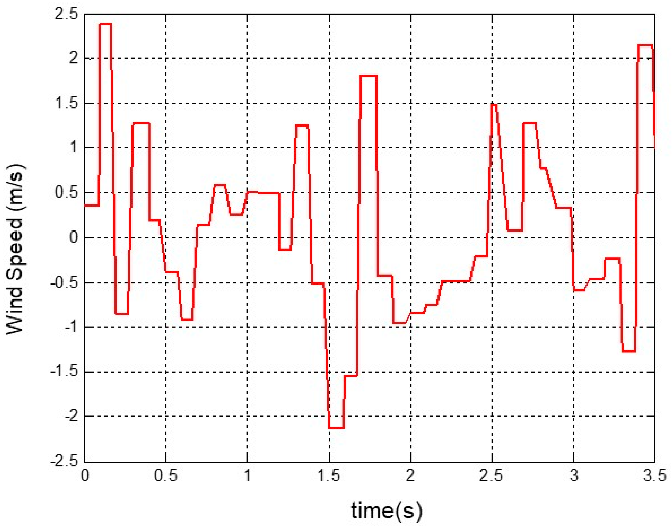
To accurately model the induction generators within the wind turbine structure, it’s essential to incorporate a wind model into the system as the primary input applied to the wind turbine. The wind model significantly influences the system’s output characteristics and behavior, and a more realistic representation leads to a more reliable output response. In a suitable nonlinear approximation, the wind behavior can be represented by a white noise signal passed through a Kalman filter. The wind speed curve is illustrated in Figure 2.
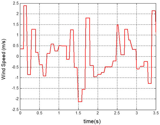
Figure 2.
Variable wind speed for DFIG system.
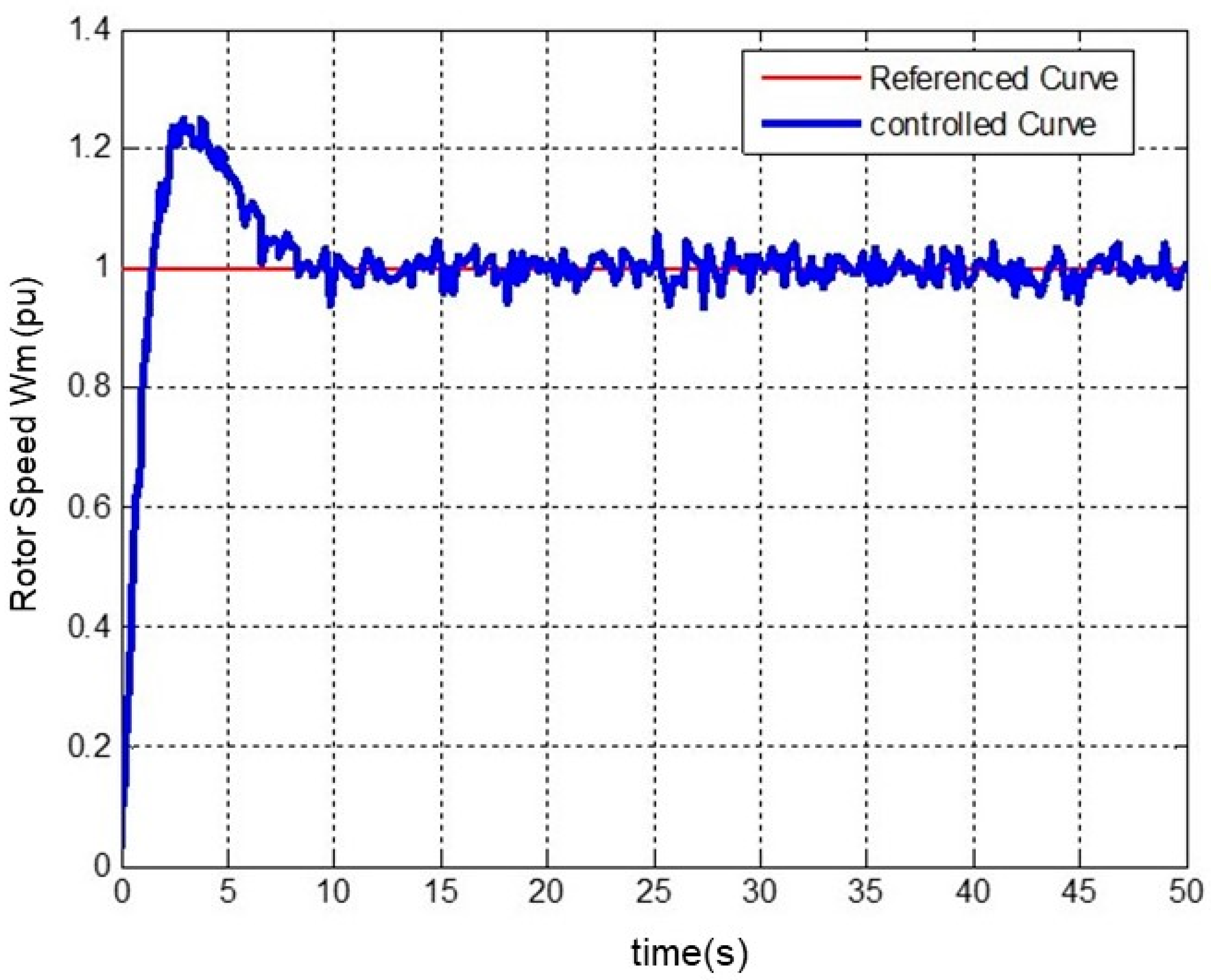
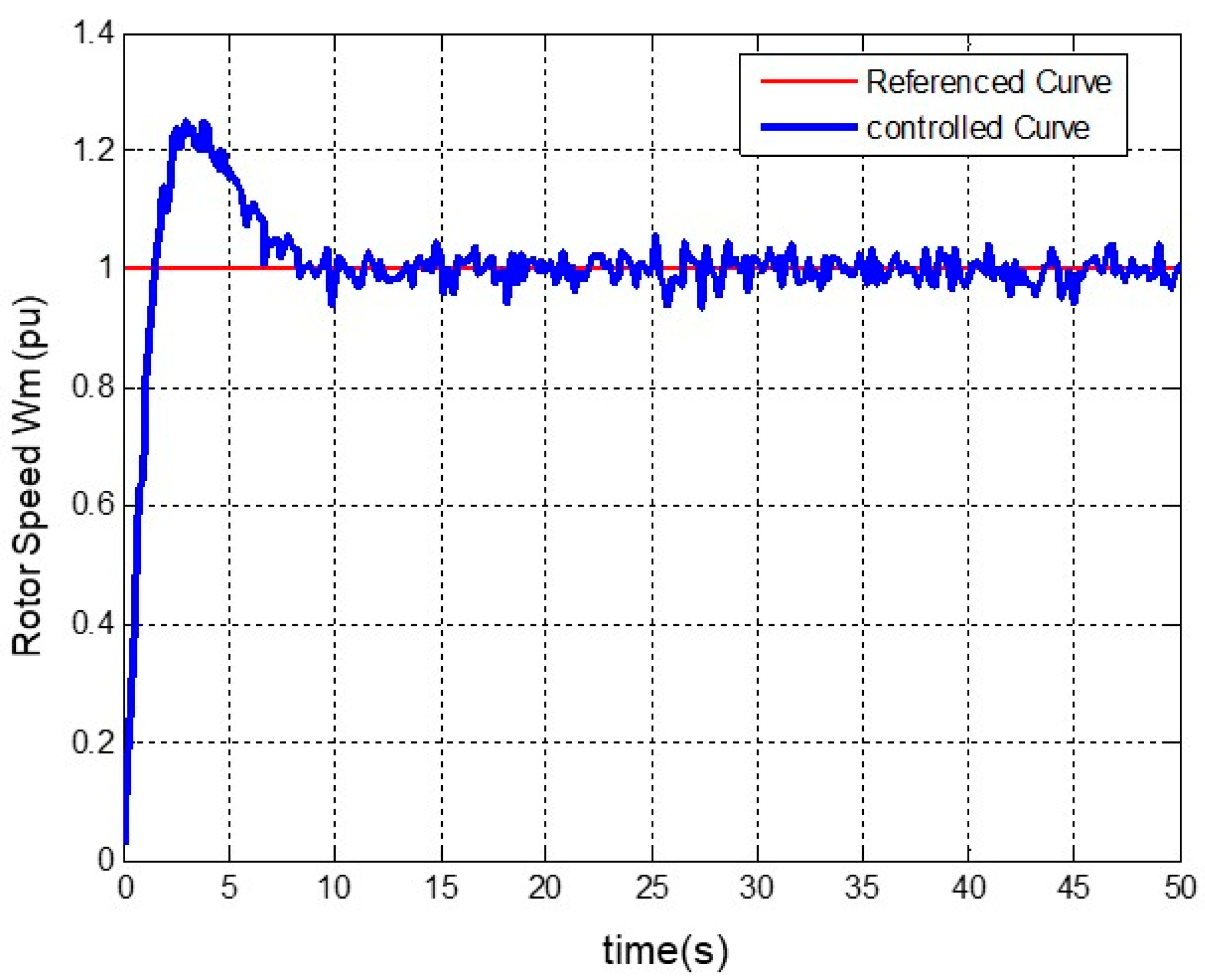
The initial step to assess the functional accuracy of the designed nonlinear MPC based on the Lyapunov function is to examine the curves obtained for the system outputs resulting from applying the reference inputs. After applying the input of Figure 2 to the system, its outputs, which include rotor speed (), pitch angle (β), active power (P), and reactive power (Q), are shown in Figure 3, Figure 4, Figure 5 and Figure 6.
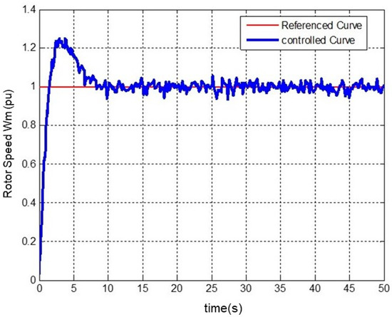
Figure 3.
Stabilization of the generator rotor angular speed by applying a fixed input.
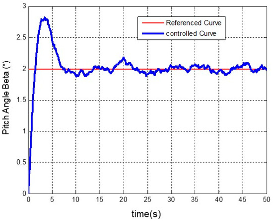
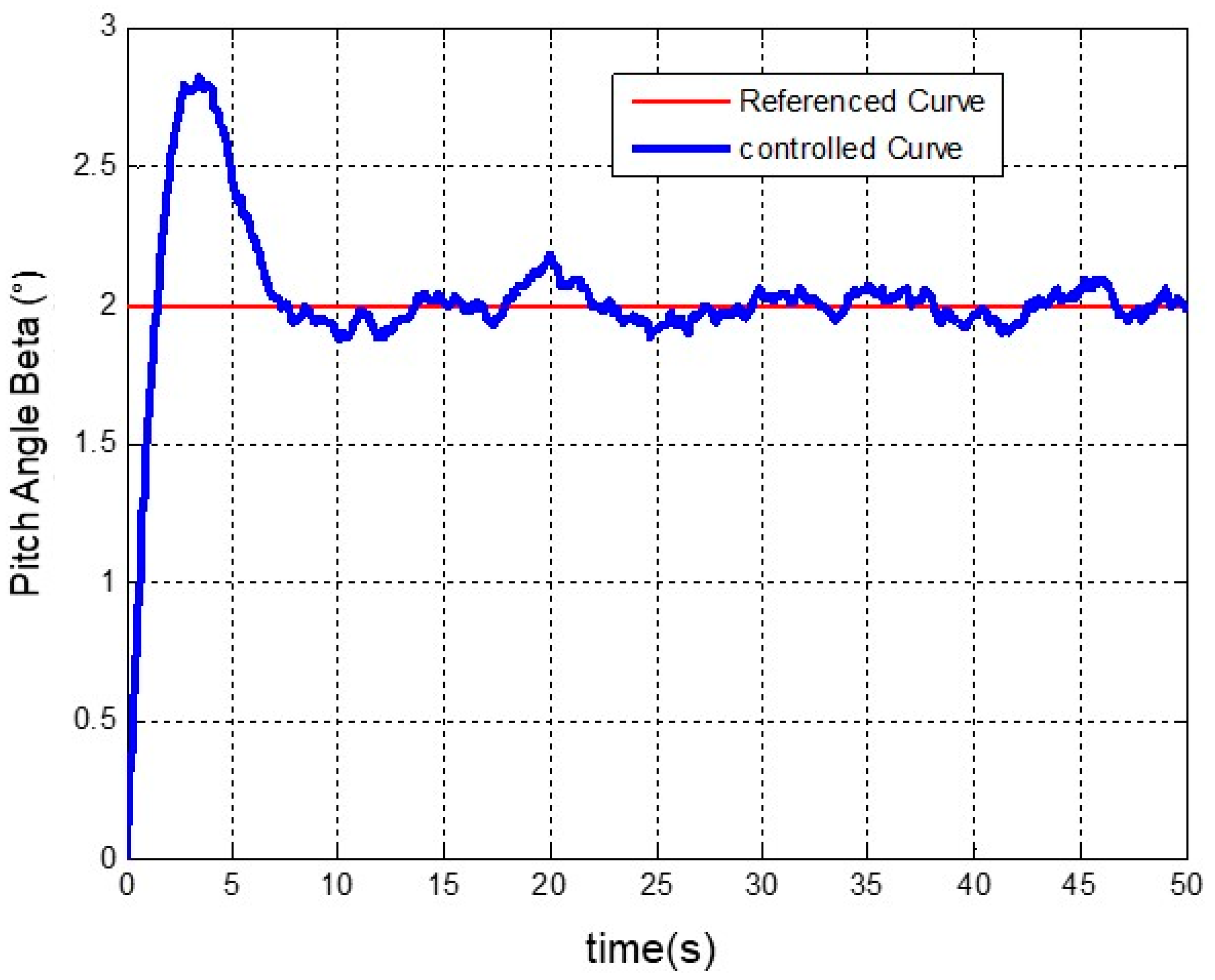
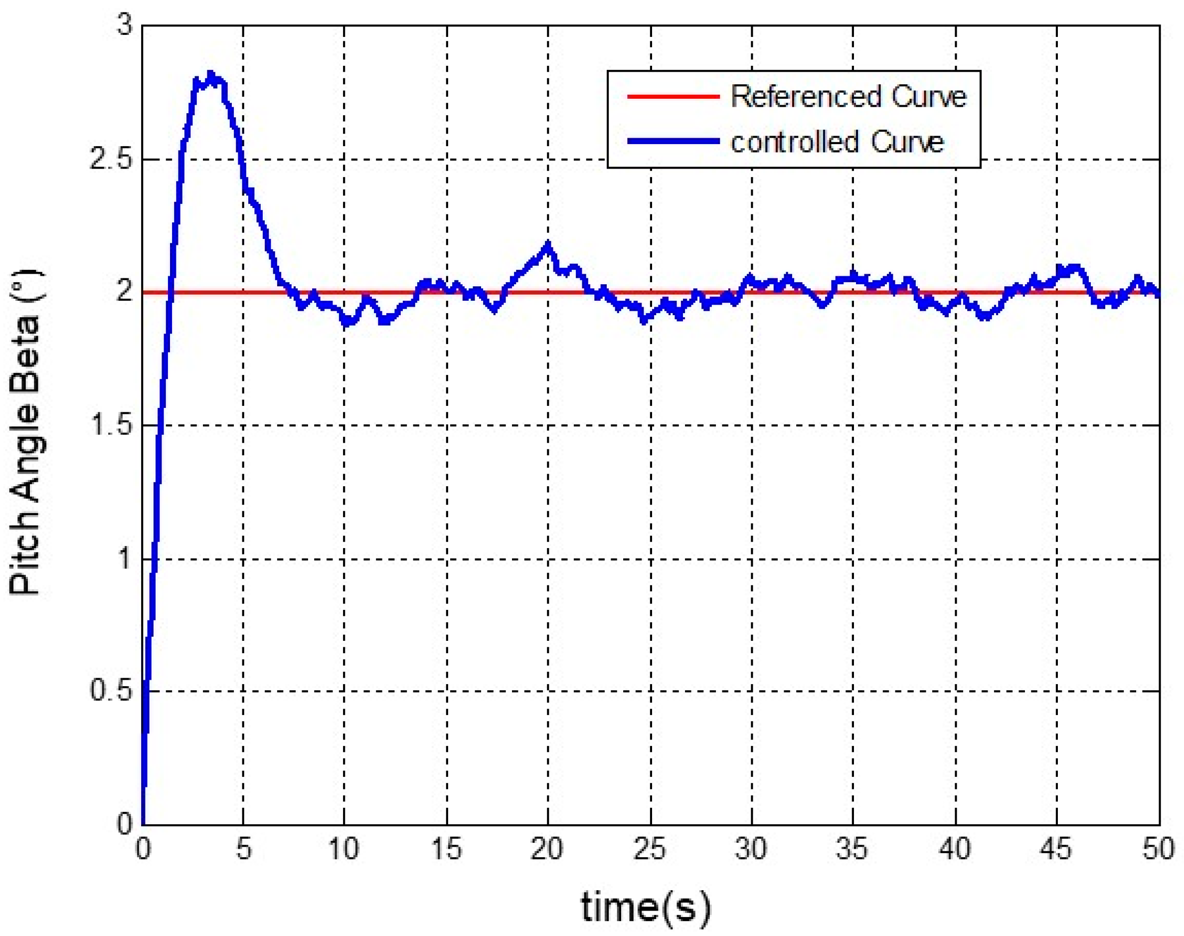
Figure 4.
Stabilization of the generator pitch angle by applying a fixed input.
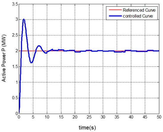
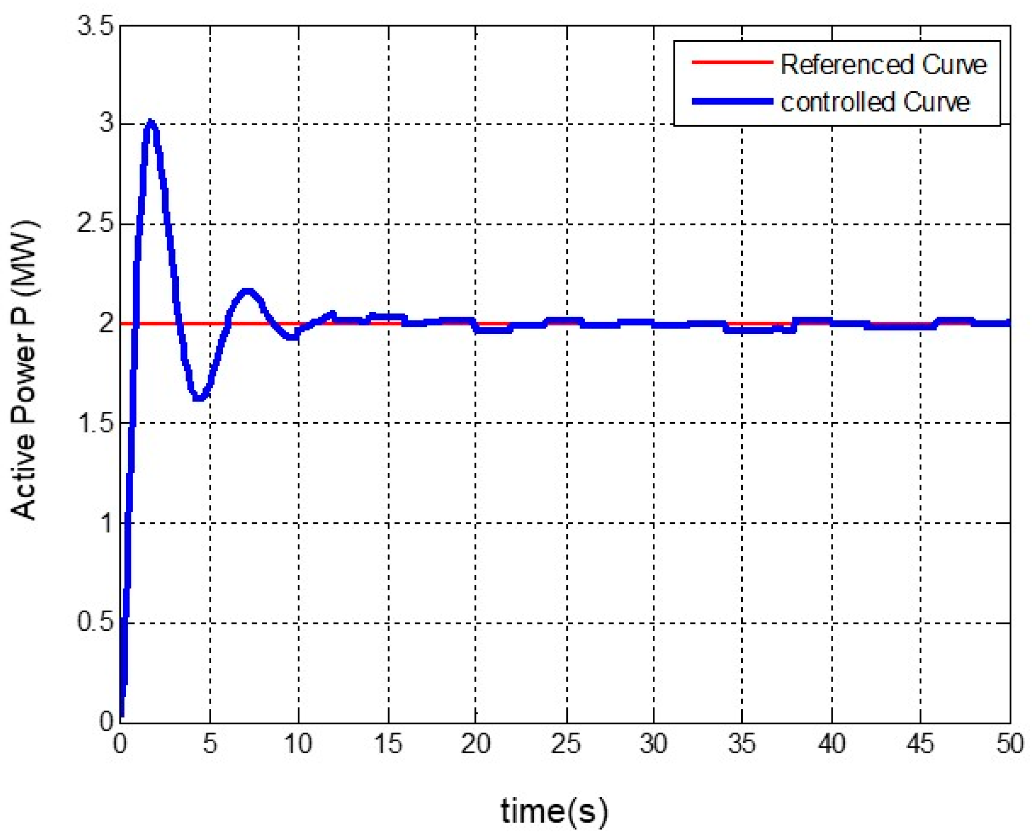
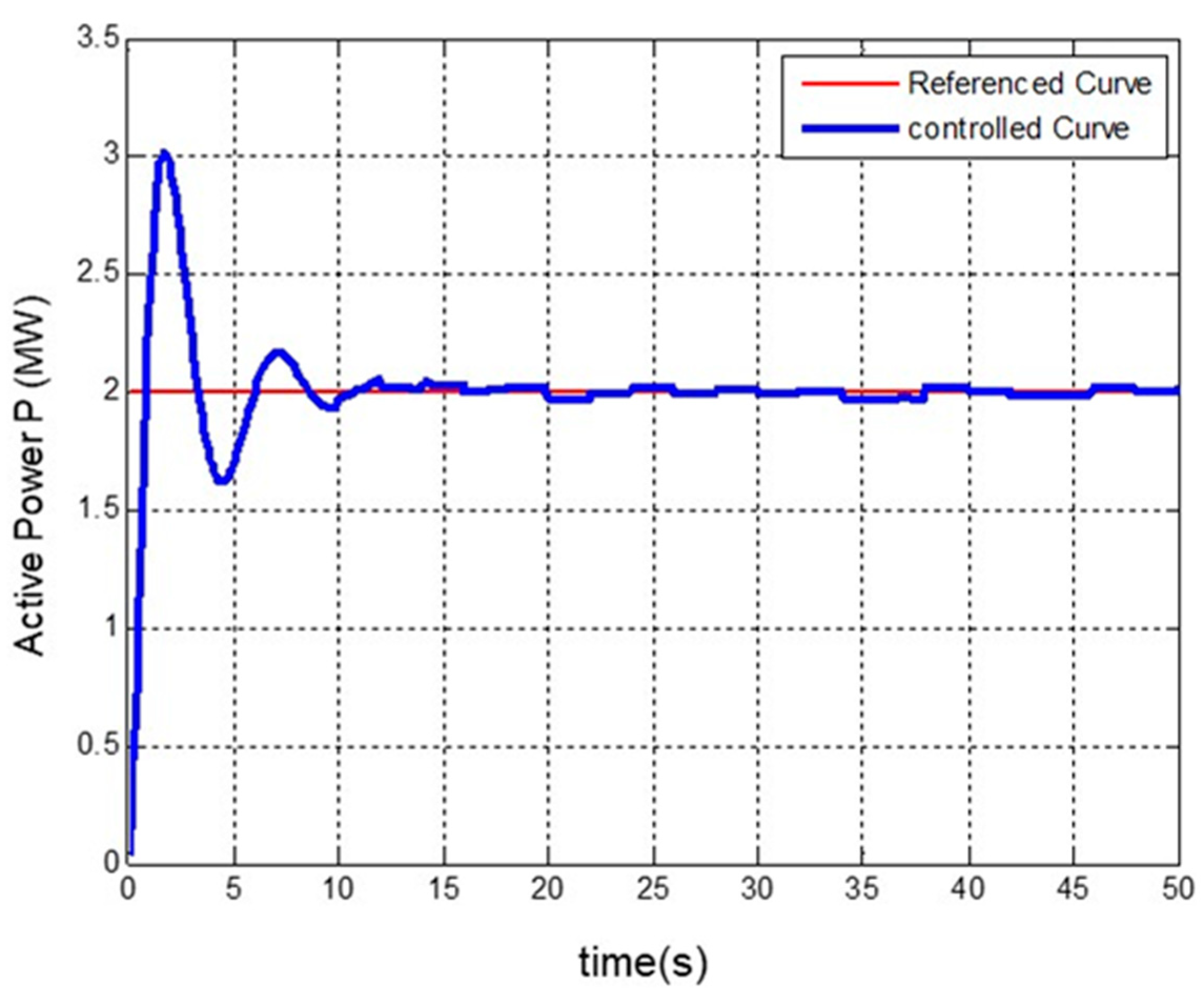
Figure 5.
Stabilization of the generator’s active power by applying a fixed input.
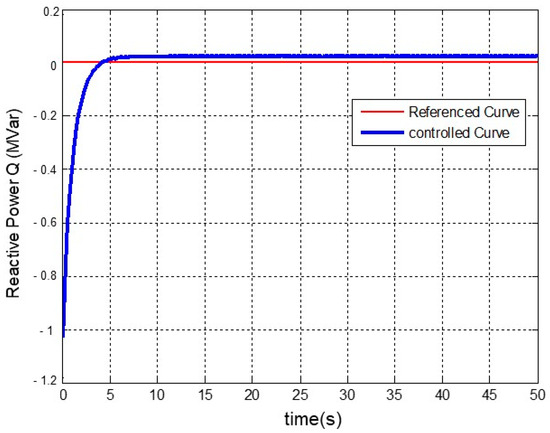
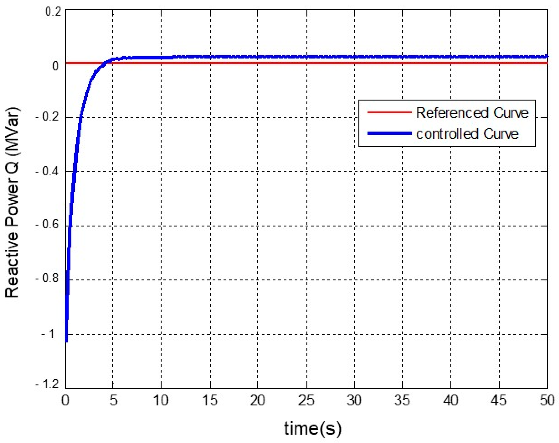
Figure 6.
Stabilization of the generator reactive power by applying a fixed input.
In the performed simulations, the steady state values for the system outputs are considered as follows:
As depicted in Figure 3, the rotor’s angular speed experiences minor fluctuations around the 1 pu speed after surpassing its overshoot. Eventually, it stabilizes at the value of 1 pu. As the oscillations’ amplitude is extremely small, they can be disregarded, and the rotor’s angular velocity response can be considered stable.
In Figure 4, it is apparent that the pitch angle curve of the generator exhibits a response closely mirroring the angular speed of the rotor. Following the overshoot point, the pitch angle curve undergoes oscillations around a consistent value. Upon the completion of the transient period, the pitch angle curve stabilizes, fluctuating around 2°, with negligible amplitude in these fluctuations. Consequently, it can be asserted that this response is entirely stable.
In Figure 5, it can be observed that the reactive power response curve has reached 3 MW during the transient period and then oscillates around 2 MW with a small range of fluctuations. Similar to the previous curves, the response can be considered stable due to the minor fluctuation range. Figure 5 depicts the stabilization of the generator’s active power through the application of a fixed input.
As shown in Figure 6, the reactive power curve does not have an overshoot point. After reaching zero reactive power, it stabilizes within a numerical range near zero.
Upon careful examination of Figure 3, Figure 4, Figure 5 and Figure 6, it is evident that the system outputs for the nonlinear MPC law based on the Lyapunov function are significantly more favorable compared to the results obtained with conventional control strategies. The comparison of the obtained results indicates that the curves have exhibited significantly better performance in terms of convergence speed, amplitude, and the number of oscillations. This serves as evidence of the superiority of Lyapunov-based nonlinear MPC over conventional control methods. Additionally, it is evident that the noise in the output curves is significantly reduced. This reduction can be attributed to the accurate filtering of the wind speed noise signal used as the input to the system.
In order to thoroughly assess the performance of the nonlinear MPC based on the designed Lyapunov function, an arbitrary variable input signal is applied to the system, and the resulting outcomes are depicted in the following Figure 7, Figure 8, Figure 9 and Figure 10. Evaluation of Figure 7, Figure 8, Figure 9 and Figure 10 indicates that the nonlinear MPC strategy based on the designed Lyapunov function, intended for variable inputs, has also yielded satisfactory results. Although the stabilization of reactive power fluctuations is not optimal, considering the nonlinear nature of the wind turbine system and the variable characteristic of the wind speed parameter, it can be concluded that overall acceptable results have been achieved.
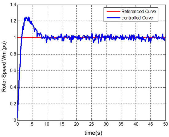
Figure 7.
Stabilization of the generator’s rotor angular speed by applying a variable input.
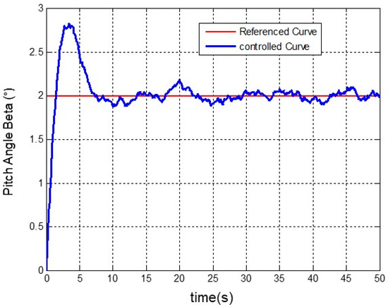
Figure 8.
Stabilization of the generator’s pitch angle by applying a variable input.
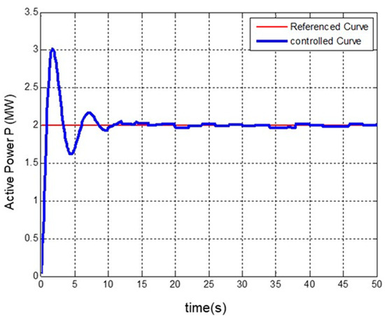
Figure 9.
Stabilization of the generator’s active power by applying a variable input.
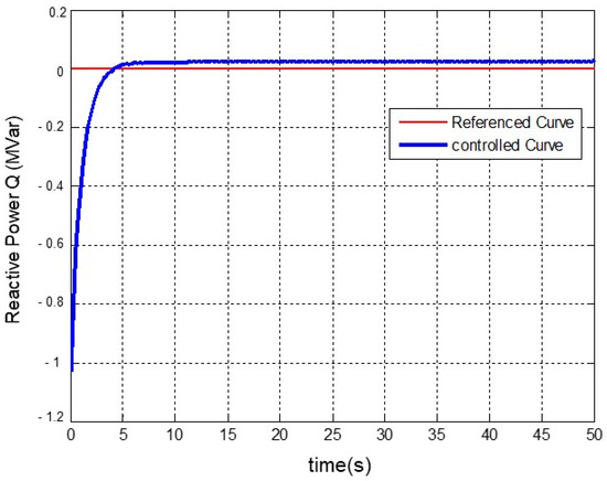
Figure 10.
Stabilization of the generator’s reactive power by applying a variable input.
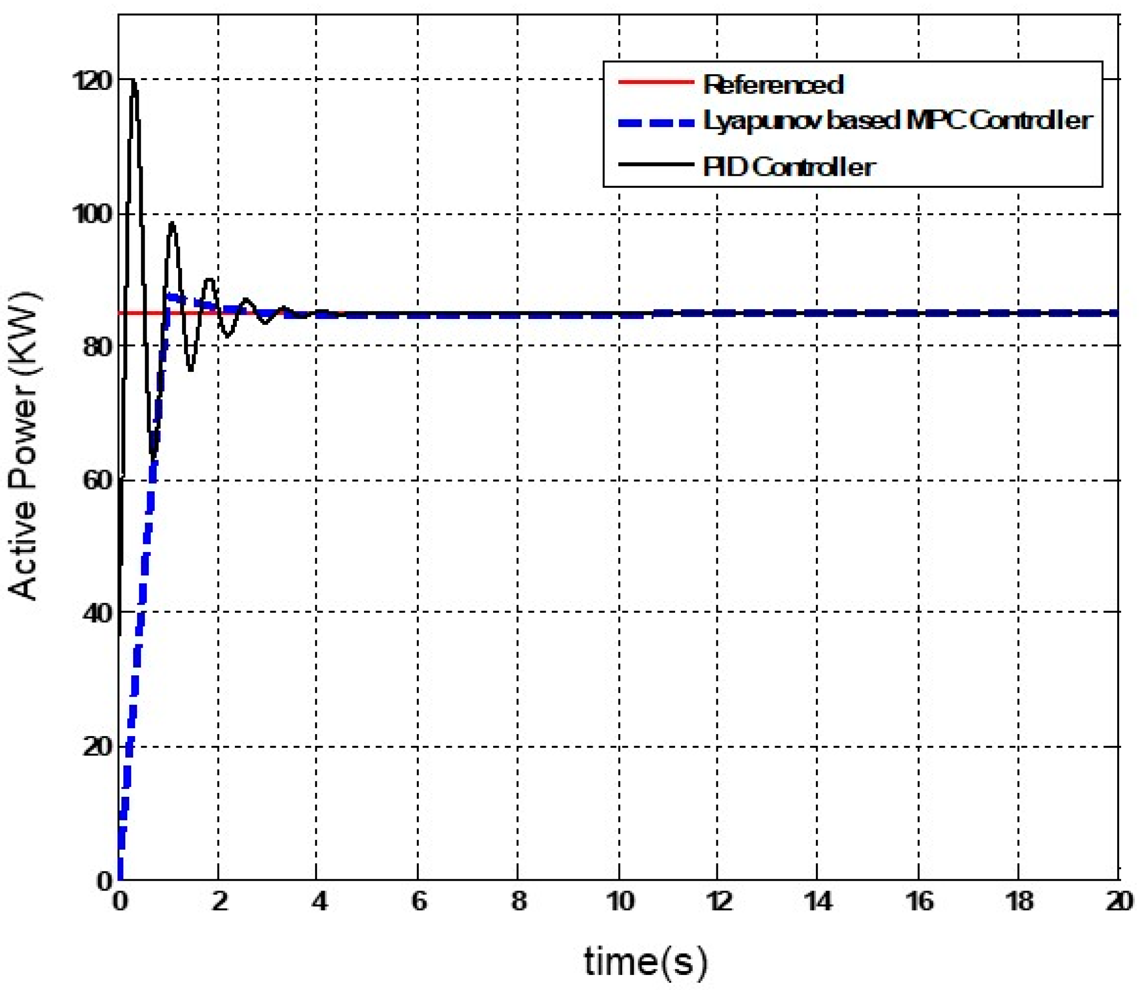
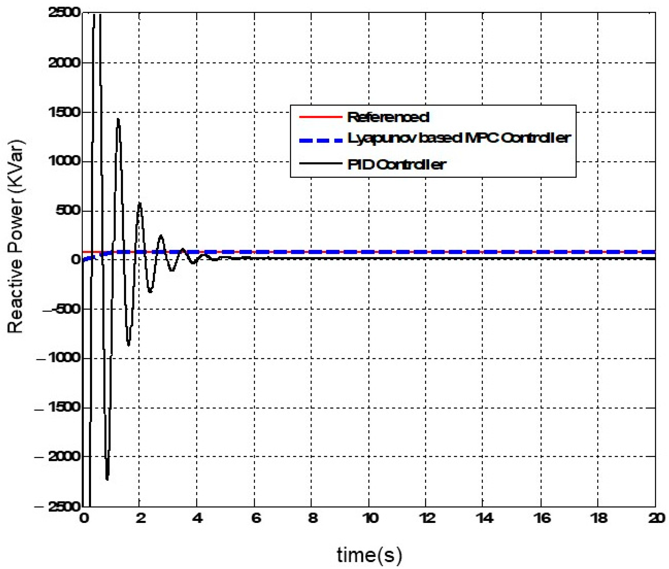
To validate the proposed method outlined in this paper, we conducted a performance comparison with a control mechanism based on the PID controller. The responses in Figure 11 and Figure 12 demonstrate the active and reactive power of the generator, respectively, when using the nonlinear MPC and PID control structure.
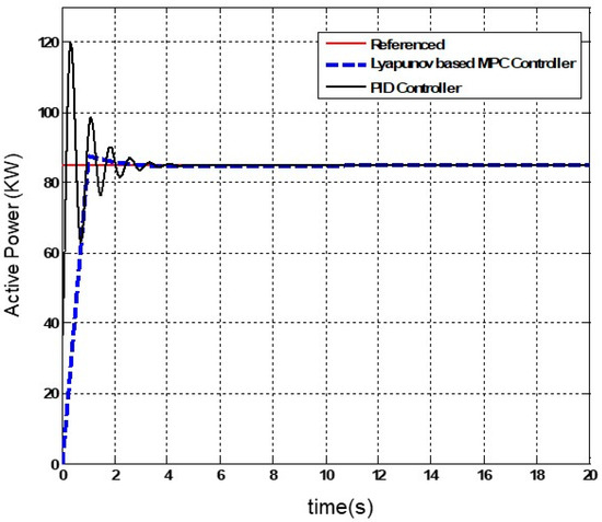
Figure 11.
Comparison of the response obtained from the proposed mechanism and the PID controller for the active power.
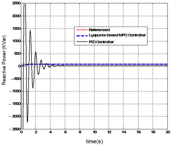
Figure 12.
Comparison of the response obtained from the proposed mechanism and the PID controller for the reactive power.
The study acknowledges the importance of performing a robustness analysis to evaluate the performance of the proposed control strategy under diverse operational conditions, disturbances. A thorough examination has been conducted, offering insights into the system’s resilience and pinpointing potential areas for further improvement. After recognizing system instability in open-loop mode, the initial deployment of a conventional Model Predictive Controller (MPC) results in suboptimal performance. Consequently, a robust methodology is introduced, incorporating a Kalman filter to mitigate wind input noise, coupled with a nonlinear MPC and Lyapunov function. Rooted in the genuine and nonlinear system model, this approach guarantees controller stability under varying conditions. Implemented within the MATLAB 2021b environment, widely utilized in scientific and engineering applications, the robustness analysis unveils the stability of the controlled doubly fed induction generator (DFIG) system across diverse scenarios.
The viability of implementing the proposed control strategy for doubly fed induction generators (DFIGs) in real-time systems is a crucial aspect for its practical application in wind turbines. A detailed assessment of computational requirements is imperative to ensure alignment with the processing power, memory, and communication bandwidth constraints inherent in real-time environments. Examining the strategy’s practical deployment entails evaluating its adaptability to hardware limitations, communication protocols, and integration with existing control systems in operational wind turbines. Real-world implementation serves as a vital validation step, enabling a comprehensive evaluation of the strategy’s performance under dynamic and unpredictable conditions. Successfully addressing these considerations not only validates the proposed control strategy but also positions it as a reliable and efficient solution for enhancing wind turbine control in real-world scenarios.
4. Conclusions
This paper’s objective is to model and control a representative wind turbine by stabilizing the characteristics of the doubly fed induction generator (DFIG) integrated into the turbine’s structure. The research is structured into three primary parts. The first part focuses on introducing a novel and accurate model for the system. To accomplish this, various research studies were reviewed to develop a comprehensive and precise model of induction generator systems. Eventually, a nonlinear model was selected for a variable-speed wind turbine. Subsequently, the conventional model predictive control (MPC) was selected as the stabilizing mechanism for the DFIG system, given its widespread use in industrial control and cost-effectiveness in implementation. Considering that the modeled induction generator system in this research is nonlinear and subject to noise and disturbances, it is evident that relying solely on conventional MPC is insufficient. Therefore, there is a need to integrate it with a suitable controller. The suboptimal performance can be attributed to two main reasons. Firstly, the wind speed input, characterized by noise and uncertainty, was not adequately filtered. Secondly, the conventional MPC’s limitations in stabilizing nonlinear systems may have contributed to the observed issues. To address these challenges, a solution was proposed that involved implementing a Kalman filter to eliminate noise from the wind speed input. Additionally, a combined control strategy was introduced, integrating nonlinear MPC based on the Lyapunov function to overcome the limitations observed in the conventional MPC structure and stabilize the modeled DFIG system. This choice was made to ensure stability in the system and to deal with unwanted inputs in the modeled nonlinear system. The results demonstrated that the combined nonlinear MPC strategy based on the Lyapunov function successfully addressed the limitations of conventional MPC. Moreover, it exhibited improved performance compared to PID based control approach, marking a significant advancement in the control of the wind turbine system. Among the limitations of this paper is the simultaneous use of several distributed generation units in the proposed mechanism, as well as the consideration of stochastic programming to solve the problem.
Author Contributions
Methodology, K.M., R.W. and H.N.; Software, K.M.; Validation, X.W. and W.F.; Writing—original draft, K.M., R.W. and H.N.; Writing—review & editing, X.W. and W.F.; Supervision, W.F. All authors have read and agreed to the published version of the manuscript.
Funding
This work was partly supported by Zhejiang Province Postdoctoral program (No. 301816) and the Research and Development Project of China Huadian Corporation LTD. (No. CHDKJ-21-01-98).
Institutional Review Board Statement
Not applicable.
Informed Consent Statement
Informed consent was obtained from all subjects involved in the study.
Data Availability Statement
Data available on request due to restrictions. The data presented in this study are available on request from the corresponding author (Ruojin Wang).
Conflicts of Interest
Authors Kuichao Ma and Wei Fan were employed by the company Huadian Electric Power Research Institute Co., Ltd. The remaining authors declare that the research was conducted in the absence of any commercial or financial relationships that could be construed as a potential conflict of interest.
References
- Narayanan, A.; Mets, K.; Strobbe, M.; Develder, C. Feasibility of 100% renewable energy-based electricity production for cities with storage and flexibility. Renew. Energy 2018, 134, 698–709. [Google Scholar] [CrossRef]
- Ahmad, T.; Zhang, H.; Yan, B. A review on renewable energy and electricity requirement forecasting models for smart grid and buildings. Sustain. Cities Soc. 2020, 55, 102052. [Google Scholar] [CrossRef]
- Spreafico, C.; Landi, D.; Russo, D. A new method of patent analysis to support prospective life cycle assessment of eco-design solutions. Sustain. Prod. Consum. 2023, 38, 241–251. [Google Scholar] [CrossRef]
- Song, D.; Zheng, S.; Yang, S.; Yang, J.; Dong, M.; Su, M.; Joo, Y.H. Annual energy production estimation for variable-speed wind turbine at high-altitude site. J. Mod. Power Syst. Clean Energy 2020, 9, 684–687. [Google Scholar] [CrossRef]
- Peng, X.; Yao, W.; Yan, C.; Wen, J.; Cheng, S. Two-stage variable proportion coefficient based frequency support of grid-connected DFIG-WTs. IEEE Trans. Power Syst. 2019, 35, 962–974. [Google Scholar] [CrossRef]
- Gebru, F.M.; Khan, B.; Alhelou, H.H. Analyzing low voltage ride through capability of doubly fed induction generator based wind turbine. Comput. Electr. Eng. 2020, 86, 106727. [Google Scholar] [CrossRef]
- Chhipą, A.A.; Chakrabarti, P.; Bolshev, V.; Chakrabarti, T.; Samarin, G.; Vasilyev, A.N.; Ghosh, S.; Kudryavtsev, A. Modeling and Control Strategy of Wind Energy Conversion System with Grid-Connected Doubly-Fed Induction Generator. Energies 2022, 15, 6694. [Google Scholar] [CrossRef]
- Huang, J.; Zhang, L.; Sang, S.; Xue, X.; Zhang, X.; Sun, T.; Wu, W.; Gao, N. Optimized series dynamic braking resistor for LVRT of doubly-fed induction generator with uncertain fault scenarios. IEEE Access 2022, 10, 22533–22546. [Google Scholar] [CrossRef]
- Liao, J.; Mastoi, M.S.; Wang, D.; Sheng, S.; Zhou, X.; Haris, M. Research on integrated control strategy of doubly-fed induction generator-based wind farms on traction power supply system. IET Power Electron. 2022, 15, 1340–1349. [Google Scholar] [CrossRef]
- Al-Khamis, O.A.-A.; Gumus, B. Comparison and performance analysis of model predictive control developed by transfer function based model and state space based model for brushless doubly fed induction generator. J. Electr. Eng. Technol. 2023, 18, 111–121. [Google Scholar] [CrossRef]
- Nie, Y.; Zhang, J.; Liu, T.; Cui, J.; Zhang, L. Low-voltage ride-through handling in wind farm with doubly fed induction generators based on variable-step model predictive control. IET Renew. Power Gener. 2023, 17, 2101–2112. [Google Scholar] [CrossRef]
- El Alami, H.; Bossoufi, B.; El Mahfoud, M.; Bouderbala, M.; Majout, B.; Skruch, P.; Mobayen, S. Robust Finite Control-Set Model Predictive Control for Power Quality Enhancement of a Wind System Based on the DFIG Generator. Energies 2023, 16, 1422. [Google Scholar] [CrossRef]
- Gulbudak, O.; Gokdag, M.; Komurcugil, H. Lyapunov-based model predictive control of dual-induction motors fed by a nine-switch inverter to improve the closed-loop stability. Int. J. Electr. Power Energy Syst. 2023, 146, 108718. [Google Scholar] [CrossRef]
- Gulzar, M.M.; Sibtain, D.; Khalid, M. Cascaded Fractional Model Predictive Controller for Load Frequency Control in Multiarea Hybrid Renewable Energy System with Uncertainties. Int. J. Energy Res. 2023, 2023, 5999997. [Google Scholar] [CrossRef]
- Aljafari, B.; Stephenraj, J.P.; Vairavasundaram, I.; Rassiah, R.S. Steady state modeling and performance analysis of a wind turbine-based doubly fed induction generator system with rotor control. Energies 2022, 15, 3327. [Google Scholar] [CrossRef]
- Younesi, A.; Tohidi, S.; Feyzi, M.R. An improved long-horizon model predictive control for DFIG in WECS with variable sampling-time. IET Renew. Power Gener. 2022, 16, 517–531. [Google Scholar] [CrossRef]
- Rodrigues, L.L.; Velasquez, O.C.; Duque, E.R.C.; Vilcanqui, O.A.C.; Filho, A.J.S. Fake algebraic Riccati equation applied to model predictive control for doubly fed induction generator direct power control. IET Electr. Power Appl. 2023, 17, 1390–1400. [Google Scholar] [CrossRef]

Disclaimer/Publisher’s Note: The statements, opinions and data contained in all publications are solely those of the individual author(s) and contributor(s) and not of MDPI and/or the editor(s). MDPI and/or the editor(s) disclaim responsibility for any injury to people or property resulting from any ideas, methods, instructions or products referred to in the content. |
© 2024 by the authors. Licensee MDPI, Basel, Switzerland. This article is an open access article distributed under the terms and conditions of the Creative Commons Attribution (CC BY) license (https://creativecommons.org/licenses/by/4.0/).