
Stability Analysis of the Exploitation System with Room and Pillar by Analytical Methods

Mining Engineering, Surveying and Civil Engineering Department, Faculty of Mines, University of Petrosani, 332006 Petrosani, Romania
Appl. Sci. 2024, 14(5), 1827; https://doi.org/10.3390/app14051827
Submission received: 20 January 2024
/
Revised: 12 February 2024
/
Accepted: 21 February 2024
/
Published: 23 February 2024
Abstract
:The mining method that is still often used in salt deposits is the room-and-pillar mining method, in which the dimensioning of the most requested element in the system is followed. The pillars are the elements subjected to the greatest loads. Knowing the size and distribution mode of the secondary state of stress—deformation—is a necessity that can lead to the design and realization of stable, reliable underground excavations. This paper proposes an analytical assessment model of the secondary stress state in the pillars between the operating rooms, as well as in the whole system room–pillar–floor, based on the results obtained from laboratory research through modeling and in situ research. For this purpose, the evaluation of the secondary stress state was carried out considering the following methods: (1) the dimensioning method based on the theory of limit equilibrium, taking into account the effective stress in the pillars; and (2) the mechanics of the continuous environment based on the design of some analytical models for evaluating the secondary stress-deformation state in the pillar and floor. The exploitation of one of the largest salt deposits in Romania is used as a case study, and the stability of the exploitation system with rooms and pillars is evaluated by analytical methods. The secondary state of tension was calculated at different points on the height of the pillar. Through the proposed algorithm, the value of the axial component of the secondary stress state at different points along the axis of a pillar located at a depth of 100 m varies between 1.498 and 1.657 MPa, compared to the value obtained by the finite element method and in situ measurements, which was 1.64 MPa. The comparison revealed a high degree of agreement between the results obtained for the depth of 100 m using both the FEM and laboratory and in situ measurements. This suggests that the proposed algorithm is a reliable method for predicting the secondary stress state. The presented algorithm can be extended in the field of mining deposits, where mining methods with rooms and pillars are used.
1. Introduction
A series of inelastic effects are frequently observed, both in the laboratory and especially in underground works. Among the materials, or, more correctly, the rocks, that present such effects, salt is the most studied example due, in particular, to the numerous underground works (drilling, salt mining, underground storage) carried out in the underground saline formations [1,2,3]. The behavior of this material is very complex [3,4]. Many scholars have studied the deformation behavior of rock salt and the influence of the stress state on the stability of the resistance structures (room, pillar, and floor) carried out in the salt massifs. Rock salt formations (seams and lenses) were considered the geological environment favorable for the deep storage of radioactive waste, petroleum products, and industrial waste [3,5,6,7,8]. For this reason, salt deposits have been the subject of numerous studies and research carried out in laboratories around the world. For the knowledge of a salt massif and the description of its deformation behavior, and implicitly, in order to analyze the stability of the underground works performed in such massifs, it is necessary to know in the first stage the main properties that need to be taken into account and studied: geological, physical, mechanical, and deformation characteristics [1,4,6]. The basic parameters considered must offer the possibility of obtaining the necessary data and information to be able to elucidate the geomechanical processes that manifest themselves in the salt massif and establish analytical methods and models for the interpretation of these processes [8]. Based on them, an efficient design can be carried out on the geometric and technological parameters of the salt exploitation methods, especially in conditions where the exploitation depth increases [9,10,11]. In order to characterize the physical state of the salt and its influence on solving the problem of stability and reliability of the geometric elements (pillars, slabs, etc.) of the salt exploitation methods, it is necessary to know the value of the main physical properties, namely: specific gravity, volumetric weight, natural humidity, compactness, and porosity [9,12,13,14,15]. Importance for the field of geomechanics is the knowledge of the two aspects of the mechanical behavior of rocks, that is, rock strength and rock mass deformability. These aspects have different meanings depending on the analyzed situation [16]. In the stability studies of mining works, these aspects are of primary importance in the sense that if a cause causes the disturbance of the equilibrium of the rock massif, then it tends towards a new state of equilibrium, visibly characterized by deformations [11,12]. The mechanical characteristics of rocks can be determined by laboratory and/or in situ tests. The establishment and knowledge of these properties are conditioned by the fact that the mechanical parameters of the salt depend to a certain extent on its physical state, and with the passage of time, these parameters can change under the influence of different factors [9,12,15,17,18,19]. At deposits of useful mineral substances of low commercial value (rock salt, potassium and magnesium salts, some iron ores, gypsum, chalk, etc.), as well as at some rock deposits (limestone, marl, slate, kaolin, clays, etc.), the rooms and pillars mining method (pillars that can be permanently or temporarily left) was and continues to be frequently applied. At the same time, this method is also applied when we do not want to cause displacements or shocks of the rocks from the roof of the exploited deposit, which would affect the land on the surface [20,21,22]. This method allows for efficient extraction of salt while minimizing the risk of structural damage to the surrounding rock formations [8,15,23,24,25]. The pillars provide natural support to prevent the collapse of the mine and maintain stability. The pillars have the role of taking over the static loads due to the weight of the corresponding part of the deposit itself and the rock formation in the roof [14,19]. The pillars prevent caving and causing displacements that would produce subsidence and terrain subsidence. To be able to fulfill this role, the pillars must be correctly sized. The lithostatic pressure determines within the pillars compression and, less often, shear stress states, depending on their shape and size and the geological and petrographic characteristics of the salt [11,23,26]. X. S. Qin et al. [15] analyze the characteristics of pillar instability and pillar loading. To evaluate the stability of the pillars, the safety factor is used, and the results obtained lead to the conclusion that the depth and uniaxial compressive strength are the most important, followed by the height and width of the pillars, the width of the rooms, and the weight of the overlying rocks. Based on the in situ experimental tests, Majeed Y. et al. [23] performed a regression analysis to develop statistical models for the in situ stress and the in situ elastic modulus. The authors of the paper [23] developed a quick orientation chart to determine the appropriate pillar length for a given span and the required safety level. Ma H. et al. [8] study the problem of the stability of underground structures in the case of their use for the purpose of gas storage in large salt caverns. The current research points out that the major problem is that the design of safety pillars has not been systematic due to the differences in salt rock in the region, and the engineering of salt pillar design still relies on experience.
The time deformations of salt play an important role in the design calculations, dimensioning, and ensuring the stability of underground works (cavities filled with brine or rooms and pillars), which depend a lot on the solubility of the salt in water and its permeability to gas and brine [3,5,6,14,27]. The rheology of rock salt deposits is much more complex compared to others because they are the place where phenomena of different natures take place, for example, phenomena related to the polycrystalline structure of the salt (dislocation movements, polygonization, interactions between crystals, etc.) or phenomena related to the high solubility of NaCl in water (phenomena such as brine migration, fluid-assisted matter transport, scarring, etc.); phenomena related to cracking and fracturing are common to all rocks [14,28,29]. These are coupled with other phenomena that influence the mechanical, thermal, hydraulic, and chemical behavior of the salt [28,29,30]. At the current stage, the theoretical treatment of the pressure regime includes a large number of problems; however, difficulties arise when solving the problems encountered in mining engineering practice through classical analytical methods. That is why many concerns are directed in particular towards finding research methods, respectively, appropriate calculations for the problems and precision required by the mining activity [11,12,17,18,20,24,29]; others refer to finding experimental procedures for determining the behavior of underground constructions of all kinds using different modeling systems and in situ measurements [7,8,19,20,24,25,28,29,30,31,32,33]. Finding that, in the end, the analytical way is not at all inferior to the experimental one, the analytical and numerical methods of solving the most diverse problems encountered in practice have also seen an exceptional development [34,35,36]. However, we specify the fact that the analytical development of determining the stress states and the mode of manifestation of mining pressure was not achieved at the expense of experimental research methods (numerical methods, in situ measurements) and vice versa. Where the mathematical models built for the representation of random processes, no matter how general they are, cannot be sufficient to represent all types of phenomena and processes that we know or that the mining technique imposes on us, experimental research procedures are welcome.
From a mathematical point of view, the problem of determining the optimal values consists of the minimization or maximization of certain functions subject to restrictions imposed by the nature of the considered processes based on a certain performance index. In recent times, many of the numerical methods have been abandoned in favor of new methods suitable for the computing technique. This is possible only if σ presents “finite” values on the intermediate surfaces of the elements. The problem of the stability of an empty space created underground, respectively the safe and economical dimensioning of the support of mining opening and preparation works, as well as exploitation (in the case of rooms), requires a fair assessment of the stress state created by the displacement phenomenon of the massif-support system, of the effect of the inhomogeneity of these stresses, as well as the influence of the anisotropy factor of heterogeneity and time. This can be conducted analytically by using the finite element method. The salt exploitation method with rooms and pillars forms a unique spatial system. From this, it follows that the necessity of establishing in any concrete situation an optimal correlation between the parameters of the room, the pillar, and the area of the rock massif is certain. Usually, in each specific case, the dimensioning of the most requested element in the system is sought, and depending on its parameters, the other parameters of the system are established. In the case of the exploitation method with rooms and pillars, the most requested elements are the pillars. In the case of the reopening of some mining fields within the salt panels and the exploitation in depth with square pillars, the establishment of the optimal parameters of the elements of the exploitation system requires the establishment of the loads that appear in the surrounding salt massif (the natural stress state); the qualitative-quantitative determination of the way of distribution of the secondary stress state in the pillars; evaluating the bearing capacity of the pillars; and establishing their geometric elements [27,37,38,39]. The way of appearance, distribution, and manifestation of the secondary stress state, as well as its magnitude, is not only a characteristic of the salt massif because it is not dependent only on its quality but is a function of the “complete and inseparable interaction” of a complex of natural, technical, mining, and organizational factors [7,11,12,13,14,15,22,23,31,36,39,40]. Studies related to the analytical assessment of the stability of the dry rock salt exploitation system with the increase in depth were carried out in the paper [12]. The authors proposed a methodology based on the interaction principle of the pillar–room–salt massif, a process by which the secondary state of stress–strain in the pillar can be established, taking into account the rheological behavior of the salt, the change in the pillar’s shape, and the extraction technology. The secondary stress state and the displacements that affect the pillar until breakage were obtained analytically using the finite element method. For the depth of 100 m, these values were verified with the data obtained from the in situ measurements made at the considered salt mine [11,12,41,42].
In this paper, the approach and solution to this problem were achieved through the following methods: (1) the dimensioning method based on the limit equilibrium theory, taking into account the effective stress in the pillars; (2) methods of the mechanics of the continuous environment based on the design of some analytical models for evaluating the secondary stress–deformation state in the pillar and floor. The comparison of the results obtained by the proposed algorithm with the available results for the depth of 100 m obtained by FEM, laboratory, and in situ measurements further validated the accuracy and consistency of the findings. According to the limit theory, with the increase in exploitation depth, the state of stress in the chamber pillar system changes, and to ensure the stability of the system, it is necessary that in a certain network of rooms and pillars, the dimensions of the pillars should grow to the detriment of reducing room opening, which leads to a significant decrease in the extraction coefficient. For the square pillars studied, due to the distribution of the vertical component of the natural stress state of gravitational origin, an analysis model of the secondary stress-deformation state was presented. Applying the analytical model for assessing the stress state in pillars and floors based on the principle of complex variables allows the evaluation of the components of the stress tensor for any depth of the exploitation system (room–pillar–floor) and, on the other hand, the investigation of the distribution of the stress state depending on the heterogeneity and the deformation behavior of the pillars.
2. Geomechanical, Technical, and Mining Considerations
In this paper, we considered the exploitation of one of the largest salt deposits in Romania. The deposit is delimited by four types of tectonic accidents consisting of major faults, geological fractures, and local lines from the roof of the deposit [12,43]. From a petrographic point of view, the salt that makes up the deposit has a macro or microcrystalline appearance, being impure with diagenetic dispersions consisting of clays, marls, sandstones, and crystalline limestones. Halite crystals appear in the form of cubes with frequent secondary fibrous developments [11,12,42,44,45]. The salt formation is considered a sedimentary rock of chemical precipitation; it has a banded texture, and its structure is homeoblastic or heteroblastic. It is a rock that can become plastic at low pressures and temperatures [12,42]. Two permeable aquifer horizons were highlighted, at 15–17 m and 45–47 m, made of fine sands. At depths of 1028–1128 m, three horizons of salinized thermal waters were identified.
In the laboratory (Figure 1), the physical, strength, and deformation characteristics of salt from categories I–III were determined, as well as for heterogeneous salt [11,12,42]. The apparent specific weight has an average value of 2.0945 × 10⁴ N/m3 for the first category of salt (compact saccharide white salt) and 2.039 × 10⁴ N/m3 for heterogeneous salt (third category). The average value of the uniaxial compressive strength varies from 24.5 MPa for the first category of salt to 17.95 MPa for heterogeneous salt. The triaxial compressive strength of salt, whether axially symmetric or cylindrical, takes average values between the limits of 24.5 and 17.95 MPa (for categories I to III), and for heterogeneous salt, it has values of 14.2 and 26 MPa. Regarding the deformation behavior, depending on the quality of the salt, from the processing of the experimental data, it was found that the modulus of elasticity of the salt varies from 733 MPa for the salt of the third category to 1850 MPa for the first category of salt. Similarly, the same experimental data highlighted a variation in Poisson’s ratio from values of 0.26 for the third category of salt to values of 0.42 for the first category. The deformations recorded after carrying out the static load tests confirm the fact that the salt has an elastic–viscous–plastic behavior [11,42,45,46]. The appearance and orientation of the cracks revealed the fact that the salt is subjected to an inhomogeneous stress state, characterized in particular by the manifestation of tensile stresses in a quasi-orthogonal direction to the compression axis. The appearance and manifestation of these stresses are partially due to the variation, size, shape, and orientation of the constituent grains of the polycrystalline salt medium [11,42].
Based on the values of the uniaxial compressive strength, this type of salt can be included in the class of rocks of low strength, according to the existing classifications in the literature [11,12,26,42,43,44,45,46,47] presenting values of the cohesion and the angle of internal friction determined both by shearing (c = 2.65 MPa and φ = 110) and in triaxial (ctriaxial = 7.9 MPa and φtriaxial = 100) specific to such rocks. Depending on the increase in lateral stresses σx = σy in the range (2.5–7.5) MPa, the triaxial compressive strength of the salt, axially symmetric or cylindrical, has average values between 22.1 and 29.58 MPa, a fact that reveals a reduced and nonlinear increase in this resistance with the application of lateral stresses.
This salt deposit is in the form of a diapir, having superior physical and mechanical characteristics compared to the other salt deposits in the country, and therefore its exploitation can be carried out by dry means. The exploitation of the deposit is performed by two exploitation methods: the exploitation method with small rooms and rectangular pillars and the exploitation method with small rooms and square pillars. The cutting method involves cutting the full face in two stages. The location network of the rooms and pillars has 30 m sides. The width of the rooms frequently varies between 14 m and 16 m. Where the exploitation is developed on several levels, the side of the pillars frequently varies between 14 m and 17 m, their size being established by applying the computation procedures based on the limit equilibrium theory. The thickness of the floor between the exploitation horizons is 8 m.
3. Methods
3.1. Stability Analysis of a Rock Salt Mining System with Rooms and Pillars Based on the Limit Equilibrium Theory
This method assumes that the stability and reliability of the room–pillar mining system are ensured if the following conditions are satisfied:
where is the value of the effective stress state in the system, and is the system resistance.
Thus, according to this limit equilibrium theory, to ensure the stability and reliability of excavations carried out in salt at increasing depths of exploitation, the following conditions must be respected:
where is the secondary stress state in pillars.
3.2. Stability Analysis of the Rooms and Pillars Exploitation System through Analytical Method
The way of appearance, distribution, and manifestation of the secondary stress state, , as well as its size, is not only a characteristic of the salt massif, because it is not dependent only on its quality but is a function of the complete and inseparable interaction of a complex of natural, technical, mining, and organizational factors. Knowing the size and distribution of the secondary stress–deformation state is an imperative that can lead to the design and realization of stable underground excavations. The problem of evaluating this secondary stress–strain state in the elements of the room–pillar–floor system has been widely studied worldwide. In this paper, we tried to find the possibility of an analytical assessment of the secondary stress state in the pillars between the operating rooms, as well as in the whole room–pillar–floor system, based on the results obtained from laboratory research through modeling and also the results of measurements performed in situ [11,45,46].
Such a problem was approached based on the following principles: (1) based on the principles and theories of the mechanics of the continuous medium; (2) a mathematical model based on the principle of the function of a complex variable.
3.2.1. Analytical Model for Assessing the Stress State in the Pillar Based on the Principles and Theories of the Mechanics of the Continuous Medium
We considered the room–pillar mining system (rooms and rectangular pillars, Figure 2, respectively, small rooms and square pillars, Figure 3) used in the solid exploitation of rock salt. Applying the theories of the mechanics of the continuous medium, it was possible to specify that the stress state of a pillar can be established starting from its assimilation with a cuboid under stress. This stress is created by the secondary stress state that manifests itself in this cuboid.
The problem was addressed spatially in the Oxyz coordinate system. The stress state of the elementary cuboid implies the existence of the nine unknowns: three normal components (σz, σy, and σx) and six tangential components, which, due to Boltzman’s principle, are reduced to three (τxy, τyz, and τzx). As a result, the evaluation of the secondary stress state requires the obtaining of the analytical expressions of these components. These expressions were determined and are given by the relations (3):
where σx, σy, and σz—the normal components of the stress state in the pillar, according to the considered cuboid; x, y, z—the coordinates of the considered point; h, b, d—the height, width and length of the pillar; E—the modulus of elasticity of the salt from which the pillar is constituted; μ—Poisson’s ratio of salt; εl—the shortening of the pillar following the compressive stress (P); A, B, C—the parameters determined with the relationships:
A0, B0, and C0 are coefficients that were established based on the correlation between the dimensions of the pillars (slenderness of the pillars, λ = h/b) and the values of Poisson’s ratio (μ).
The value of the compressive stress of the pillar results from the expression:
hence the value of the shortening (εl) is:
Starting from the expressions (3), based on the boundary conditions, the following system of equations was obtained:
The solution of this system expresses the common three-dimensional working character of the pillar with the entire room–pillar exploitation system. At the same time, it allows the research of the secondary stress state in the pillars in the context of different correlations with their dimensions, both in plan and with their height.
3.2.2. Analytical Model for Assessing the Stress State of Pillar and Floor Based on the Principle of Complex Variables
Another analytical approach for establishing the distribution of the secondary stress state is based on the principle of the method of the function of a complex variable. The underground space for which the secondary stress state is quantitatively evaluated is materialized through the salt deposit exploitation system of small rooms and rectangular pillars at different depths (H) from the surface (Figure 4).
The shape of the rooms is, therefore, rectangular, having a height (h) identical to the height of the pillars and h << H, and their length far exceeds the two dimensions, width and height. Consequently, the planar approximation can be used to determine the secondary stress state in accordance with the following analytical relations:
that are periodic with π [44]. We will consider the cartesian coordinate system as the main system, and therefore, we have:
Thus, the solution of system (8) consists of the summation of two solutions: the first solution is the tensor of the natural stress state, and the second solution is the additional components of the stress state that lead to the occurrence and manifestation of the secondary stress state on the floor of the rooms. In such a context, polynomial functions were used, based on which relations (8) are rendered in the form of functions of a complex variable:
where as a complex variable of the holomorphic function in the domain defined by the salt massif, .
According to Figure 4, between the operating rooms in sectors aj, bj (where j = 1, 2, 3,…, n and n represent the number of rooms), the pillars of width (bj − aj) are left. It follows in this case that the number of rooms is (n + 1), and the width of a room (j) − (j + 1) can be calculated with the relation (aj+1 − bj).
Denoting the width of the entire floor by 2L, the 2L/h ratio leads to a value higher than one, and as a result, in the absence of pillars, the excavation obtained can be analyzed as a gap carried out in the salt massif. Thus, the application of the plane theory is appropriate with the condition that in sectors aj and bj, at the upper edge, namely, in the ceiling of the excavation, uniformly distributed loads Pj are applied as reactions developed by the pillars (Figure 4). Based on the principles of Stamatiu [26,47] with reference to the analysis of the loads acting on the pillars and, in the context of the normal stress distribution σz at the pillar–floor contact, the expression was obtained according to which the reaction Pj, developed by the pillars, can be evaluated:
where —width of pillar j is equal to (bj − aj); according to Figure 4, μ1—coefficient of friction on the contact surface between the floor and the roof (μ1 = tgφ); φ—internal friction angle of the salt; ξ0—coefficient of lateral pressure created by Poisson’s ratio (μ):
Based on the clarifications made, the expressions (9) for the considered situation, namely, the room and pillar exploitation system, become:
in which are the components of the tensor of the natural stress state of the gravitational origin of the undisturbed salt massif and represent the first solution of relations (11). For these, we applied the Kühn–Terzaghi hypothesis in the form:
For the evaluation of the second solution, that is, establishing the additional components of the stress state , the expressions (9) for the analyzed situation led to the following form:
where u(x) and v(x) are the horizontal and vertical displacements of the floor contour; the elastic constants according to Mushelisvili [48], which are expressed as a function of Poisson’s ratio (μ) and the modulus of elasticity (E):
and the function φ(c) was determined according to [44,47] by the following conditions:
- evaluation of boundary conditions:
- -
- at the surface of the massif, the normal and tangential stresses are zero, which means that for Y = H, it follows that σz = τx z = 0, and −∞ < x < ∞;
- -
- at the contact of the floor with the pillar, for Y = 0 (Figure 4), the following conditions are valid:
- and the equilibrium equations based on the principle of Cauchy–Riemann, obtaining:
Therefore, the components of the secondary stress state tensor and the distribution of these stresses on the floor of the rooms and above the pillars can be determined based on the relationships obtained by drawing up the algorithm for the conditions of the salt massif under study.
4. Results
4.1. Stability Analysis of a Rock Salt Mining System with Rooms and Pillars Based on the Limit Equilibrium Theory
Based on the methods of the limit equilibrium principle, the stability of the exploitation system is due to the degree of stress, the dimensions of the geometric elements of the system (pillar, floor), and the exploitation depth. According to the geomechanical, technical, and mining conditions of the salt mine considered in this work [11,12,42], this statement is also highlighted by the results obtained for the four situations that were considered in the study (Figure 5):
Case 1: lroom = 16 m, lpillar = 14 m, σlim = 55.95 MPa, Ce = 31.3%;
Case 2: lroom = 15 m, lpillar = 15 m, σlim = 64.645 MPa, Ce = 30%;
Case 3: lroom = 14 m, lpillar = 16 m, σlim = 74.344 MPa, Ce = 28.6%;
Case 4: lroom = 13 m; lpillar = 17 m; σlim = 85.05 MPa, Ce = 27.1%.
The conditions (2) are shown in Figure 6 for the maximum depth H0 = 500 m; in Figure 7, these conditions are shown for the depth of 800 m and the variation in the extraction coefficient, Ce%.
The effective load that belongs to some pillars depends not only on the size of γaH but also on the lr/lp ratio (room width/pillar width), the way of distributing the stress, and the qualitative variation in the salt of the pillars. At exploitation depths of 200–250 m and values of the geometric dimensions of the room and pillar of 14 m and, respectively, 16 m, the load degree is 0.23–0.25. The extraction coefficient has a value of 35.7%, and the required height of the pillar is 8 m. The effective stress respects the condition (2) of stability (15.05 MPa < 30.55 MPa). When increasing the depths up to 350 m and the values of the geometric dimensions of the room and pillar (lr = 13 m and lp = 17 m), the condition of stability is respected. The load degree is 0.28 < 0.3, the effective stress does not exceed 20 MPa, and the required height of the pillar becomes 9 m (the value of the extraction coefficient being 31.9%). At depths of 800 m and dimensions of lr = 11 m and lp = 19 m, the load degree varies within 0.33–0.35, and the effective stress does not exceed 50% of the value of the limit stress. Under these conditions, for an extraction coefficient of 24%, the required height of the pillar should be 12 m. In fact, rheological research [42,49] showed that in terms of creep behavior, for the conditions of this mine salt, the pillars are located in the estimated stability field (0.3–0.45)σc (σc being uniaxial compressive breaking strength).
It results that, according to the theory of limit equilibrium, with the increase in exploitation depth, the stress state in the room–pillar system also changes, emphasizing the inelastic, plastic deformation character of rock salt. In such a context, to ensure the stability and reliability of the system, it is required that within a given network of rooms and pillars, the dimensions of the pillars increase at the expense of reducing the opening of the rooms. This fact leads to a significant decrease in the extraction coefficient.
4.2. Stress State in the Pillar Based on the Principles and Theories of the Mechanics of the Continuous Medium
For the proposed analytical model to evaluate the stress state in the pillar based on the theories of the mechanics of the continuous environment, the coefficients A0, B0, and C0 were determined. These were obtained for ratio values h/b: 0.1 − 3; 0.01 − 1 and λ = 0.05 − 0.4 (Table 1).
In this context, the solution was achieved by considering the real situation of rectangular pillars from a salt mine in operation in Romania at a depth of 100 m in relation to the surface; the input data were those shown in Table 2.
Figure 8 shows the diagram of the location of the points where the components of the secondary stress state in the pillar were calculated. These points resulted from the intersection of the horizontal planes along the three directions of the coordinate axes (x, y, z). Figure 9 shows the spatial distribution of the vertical component of the secondary stress state (σz) on the considered horizontal surfaces (z represents the height of the contact surface of the pillar with the floor of the room; z = h/2 is the elevation where the median surface is located in the considered pillar in the study).
The spatial distribution table of the vertical component of the secondary stress state in the pillar (σz), evaluated according to the proposed mathematical model, reveals the complicated nature of the manifestation and distribution of the secondary stress state in the pillars. Based on the results obtained from the calculation, the complete distribution diagram of the secondary stress state can be drawn, including all components of the stress tensor: the three normal components σx, σy, σz, and the tangential components τxy, τyz, and τzx.
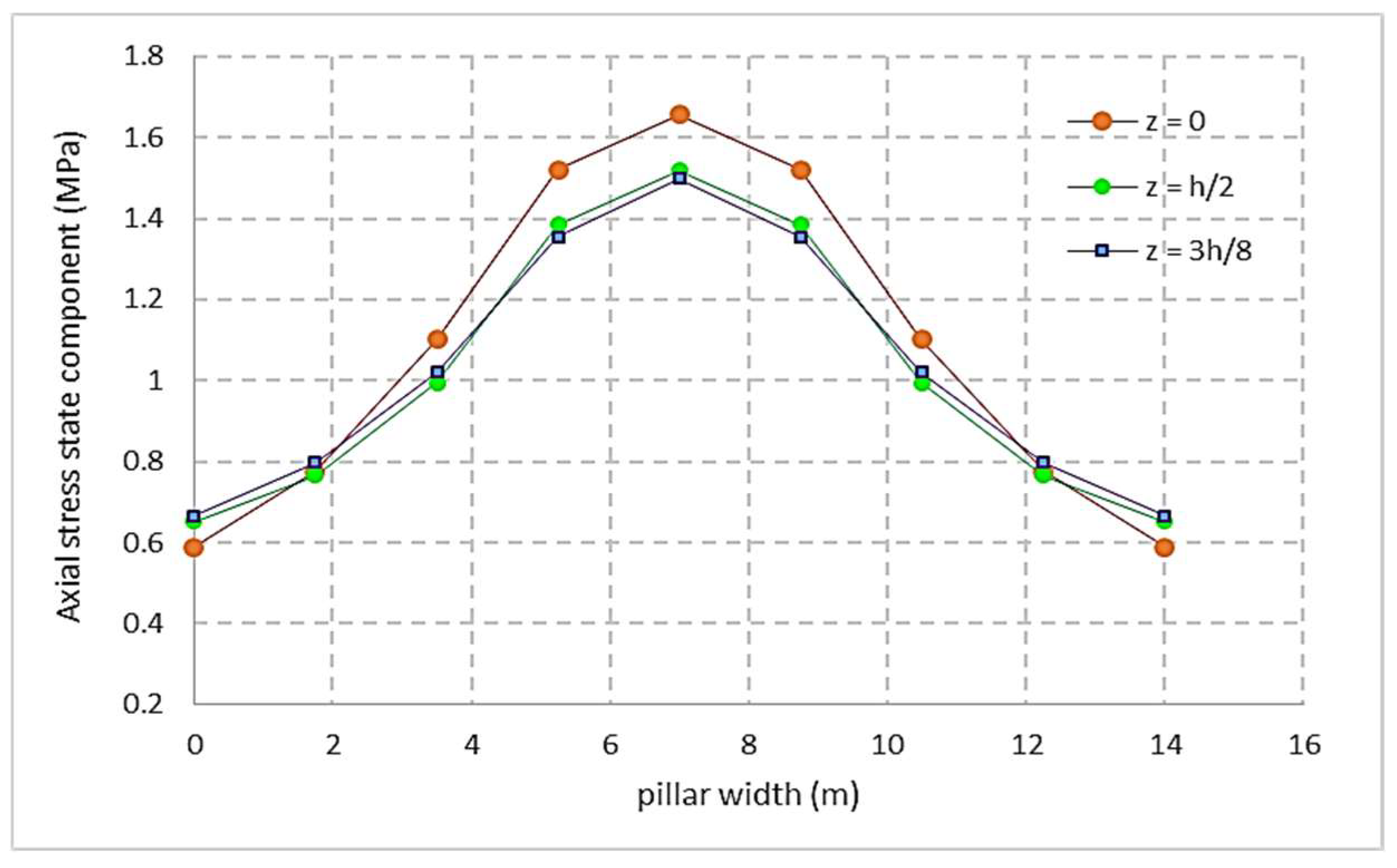
For example, Figure 10 shows the variation in the axial component of the secondary stress state at the points z = 0, z = h/2, and z = 3h/8 in the situation where the pillar has a width of 14 m and a height of 8 m.
To validate the results obtained by the proposed method, they were compared with the values obtained by FEM and verified with the data obtained from the in situ measurements. These values can be found in the paper [12,42]. Through the proposed algorithm, the value of the axial component of the secondary stress state at different points along the axis of a pillar located at a depth of 100 m varies between 1.498 and 1.657 MPa, compared to the value obtained by the finite element method and in situ measurements, which was 1.64 MPa [42]. The measurement of the stress state in the pillars was carried out using a cylindrical pressure cell made on the hydraulic principle installed in bore holes.
The comparison with the available results for the depth of 100 m obtained by the FEM, laboratory, and in situ measurements further validated the accuracy and consistency of the findings.
From the obtained results, it can be seen that the main parameters that determine the character of the distribution of the secondary stress state in the room–pillar system are the dimensions of the geometric elements of the pillar and floor correlated with the value of the Poisson’s coefficient. The modulus of elasticity (E) of the salt and the natural state of stress (especially the value of its vertical component σz = γaH) as stress produced on the exploitation system do not manifest themselves in the character of the distribution of the secondary stress state. However, these parameters influence the absolute size of the components of this stress state.
4.3. Stress State of Pillar and Floor Based on the Principle of Complex Variables
The theoretical results obtained for the considered conditions (we considered 4 rooms and 3 pillars) by applying the analytical model for assessing the stress state in pillars and floor based on the principle of complex variables revealed the occurrence and manifestation of horizontal stresses in the floor between the rooms up to 5 m in depth in relation to the exposure plan. The action of horizontal tensile stresses is reduced and spreads on the floor up to 2.5 m above the central rooms and up to 1.5 m above the rooms neighboring the undisturbed salt massif. The zone of vertical tensile stresses spreads up to 3 m on the floor of the central rooms and up to 2.5 m on the floor of the marginal rooms.
The proposed analytical model based on the principle of complex variables allows (1) the evaluation of the components of the stress tensor for any depth of location of the exploitation system and (2) the investigation of the distribution of the stress state depending on the heterogeneity and the different deformation behavior of the pillars. This methodology and the analytical results obtained are to be verified experimentally through a program of in situ measurements, along with the increase in depth.
5. Conclusions
(1) Analyzing the obtained results correlated with the in situ measurements, it can be stated that the pillars considered in this paper present a distribution of the vertical component of the secondary stress state characterized by the fact that the value of the secondary stress state is maximum on the axis of the pillar in its middle and decreases towards its exterior, and the shear stresses are maximum on the contour of the pillar and decrease towards its interior. The variation in shear stresses results in part from the inward increase in the lateral components of the stress state and a natural decrease in compressive stress as we move away from the free surfaces of the pillars. For the same cross-section, square pillars can support higher loads than rectangular pillars. Since the rectangular pillars have one side smaller than the other, they limit the development of lateral stresses. This phenomenon explains why a square pillar can support a higher load than a rectangular pillar of equal cross-section.
(2) The results obtained for the depth of 100 m were compared with the values of the stress state obtained by the finite element method, the laboratory, and in situ measurements. According to the proposed algorithm, the values of the axial component of the secondary stress state acting on the pillar located at a depth of 100 m are between 1.498 and 1.657 MPa, compared to the value obtained by the finite element method and in situ measurements, which was 1.64 MPa. This result confirms the validity of the proposed algorithm for evaluating the secondary stress state in pillars.
(3) The breaking load of the pillars remains a problem that requires corrections and improvements so that the final estimates illustrate as accurately as possible the behavior of the pillar and floor.
(4) Research can be continued so that a methodology can be created—a generalized mathematical model—that involves the whole range of factors that influence the stability of the exploitation system to be able to establish this model as a basis for efficient and safe design, ensuring an optimal extraction coefficient. This algorithm and the analytical results obtained are to be verified experimentally through a program of in situ measurements, along with the increase in depth.
Funding
This research received no external funding.
Institutional Review Board Statement
Not applicable.
Informed Consent Statement
Not applicable.
Data Availability Statement
Data are contained within the article.
Acknowledgments
I would like to thank the University of Petrosani, which provided the equipment to perform all laboratory tests.
Conflicts of Interest
The author declares no conflicts of interest.
References
- Zhang, H.; Wang, Z.; Zheng, Y.; Duan, P.; Ding, S. Study on tri-axial creep experiment and constitutive relation of different rock salt. Saf. Sci. 2012, 50, 801–805. [Google Scholar] [CrossRef]
- Chu, Z.; Wu, Z.; Liu, Q.; Liu, B.; Sun, J. Analytical solution for lined circular tunnels in deep viscoelastic Burgers rock considering the longitudinal discontinuous excavation and sequential installation of liners. J. Eng. Mech. 2021, 147, 04021009. [Google Scholar] [CrossRef]
- Zhang, G.; Wu, Y.; Wang, L.; Zhang, K.; Daemen, J.J.K.; Liu, W. Time-dependent subsidence prediction model and influence factor analysis for underground gas storages in bedded salt formations. Eng. Geol. 2015, 187, 156–169. [Google Scholar] [CrossRef]
- Toderaş, M. Analysis the natural stress state of salt massive from Praid Mine, Romania. In Proceedings of the 15th International Multidisciplinary Scientific Geo-Conference & EXPO SGEM 2015 Modern Management of Mine Producing, Geology and Environmental Protection, Albena, Bulgaria, 18–24 June 2015; Volume 3, pp. 73–80. [Google Scholar]
- Li, Z.J. Analysis and Application of Pillar Stability of Deep Salt Rock Gas Storage; Shandong University: Jinan, China, 2018. [Google Scholar]
- Fu, X.F. Stability analysis of Huangchang salt cavern underground gas storage in Jianghan Basin. J. Shanxi Datong Univ. (Nat. Sci. Ed.) 2020, 36, 73–75. [Google Scholar]
- Habibi, R. An investigation into design concepts, design methods and stability criteria of salt caverns. Oil Gas Sci. Technol.—Rev. IFP Energ. Nouv. 2019, 74, 14. [Google Scholar] [CrossRef]
- Ma, H.; Wei, X.; Shi, X.; Liang, X.; Bai, W.; Ge, L. Evaluation Methods of Salt Pillar Stability of Salt Cavern Energy Storage. Energies 2022, 15, 7570. [Google Scholar] [CrossRef]
- Jeremic, M.L. Rock Mechanics in Salt Mining; A. A. Balkema: Rotterdam, The Netherlands, 1994; p. 530. [Google Scholar]
- Junthong, P.; Khamrat, S.; Sartkaew, S.; Fuenkajorn, K. Determination of time-dependent strengths of salt pillars based on strain energy principle. Int. J. Min. Sci. Technol. 2019, 29, 273–279. [Google Scholar] [CrossRef]
- Toderas, M. The Octahedral Concept and Cubic Triaxiality in Assessment of Secondary Stress State. Min. Miner. Depos. 2020, 14, 81–90. [Google Scholar] [CrossRef]
- Toderaș, M.; Iosif, C. The Interaction Principle in the Assessment of Pillars’ Secondary Stress-Deformation State. Min. Rev. 2023, 29, 14–25. [Google Scholar] [CrossRef]
- Majeed, Y.; Abbas, N.; Emad, M.Z. Stability evaluation of room-and-pillar rock salt mines by using a flat jack technique—A case study. J. South. Afr. Inst. Min. Metall. 2023, 123, 287–298. [Google Scholar] [CrossRef]
- Berest, P.; Brouard, B.; Feuga, B.; Karimi-Jafari, M. The 1873 collapse of the Saint-Maximilien panel at the Varangeville salt mine. Int. J. Rock Mech. Min. Sci. 2008, 45, 1025–1043. [Google Scholar] [CrossRef]
- Qin, X.S.; Cao, H.; Guo, L.J. Sensitivity analysis of factors influencing pillar stability in the deep stope of underground salt mine. IOP Conf. Ser. Earth Environ. Sci. 2020, 570, 022002. [Google Scholar] [CrossRef]
- Zhang, S.Z. Analysis of the Roof-Pillar Stability of the 1# Copper Mine with the Room-Pillar Method in the Dahongshan Iron Mine; Kunming University of Science and Technology: Kunming, China, 2014. [Google Scholar]
- Singh, A.; Kumar, C.; Kannan, L.G.; Rao, K.S.; Ramanathan, A. Estimation of Creep Parameters of Rock Salt from Uniaxial Compression Tests. Int. J. Rock Mech. Min. Sci. 2018, 107, 243–248. [Google Scholar] [CrossRef]
- Laouafa, F.; Ghoreychi, M. Contribution to improve pillar analysis in abandoned room and pillar salt mines. In Proceedings of the Symposium Post Mining 2005, Nancy, France, 16–18 November 2005. [Google Scholar]
- Onica, I.; Cozma, E.; Marica, D.P. Stability Analysis of the Rock Salt Rooms and Pillars of the Ocnele Mari Saline with the Aid of the 2d Finite Element Modelling. Ann. Univ. Petrosani Min. Eng. 2011, 12, 7–17. [Google Scholar]
- Esterhuizen, G.S.; Tyrna, P.L.; Murphy, M.M. A Case Study of the Collapse of Slender Pillars Affected by Through-Going Discontinuities at a Limestone Mine in Pennsylvania. Rock Mech. Rock Eng. 2019, 52, 4941–4952. [Google Scholar] [CrossRef] [PubMed]
- Dai, H.-Y.; Li, W.-C.; Liu, Y.-X.; Jiang, Y.-D. Numerical simulation of surface movement laws under different unconsolidated layers thickness. Trans. Nonferrous Met. Soc. China 2011, 21, 599–603. [Google Scholar] [CrossRef]
- Poulsen, B.A.; Shen, B. Subsidence risk assessment of decommissioned bord-and-pillar collieries. Int. J. Rock Mech. Min. Sci. 2013, 60, 312–320. [Google Scholar] [CrossRef]
- Chen, Q.; Wu, S.; Zhao, F. Study on the mechanics and micro/macroeconomics of multiple strip-shaped pillar recovery. Arch. Min. Sci. 2020, 65, 19–33. [Google Scholar]
- Afshin, M.; Javad, G. Stability Analysis and Feasibility of Pillar Recovery Inextraction Workplace of Salt Rockmining at Ghaplogh Region at Khoy. Indian J. Fundam. Appl. Life Sci. 2015, 5, 823–837. Available online: www.cibtech.org/sp.ed/jls/2015/03/jls.htm (accessed on 17 September 2023).
- Wu, A.-X.; Huang, M.-Q.; Han, B.; Wang, Y.-M.; Yu, S.-F.; Miao, X.-X. Orthogonal design and numerical simulation of room and pillar configurations in fractured stopes. J. Cent. South Univ. 2014, 21, 3338–3344. [Google Scholar] [CrossRef]
- Stamatiu, M. Problema Dimensiunii Stâlpilor la Minele de Sare Din România; Editura Academiei: Bucharest, Romania, 1959. [Google Scholar]
- Hunsche, U. Results and interpretation of creep experiments on rock salt. In Proceedings of the First Conference on the Mecanical Behaviour of Salt, State College, PA, USA, 9–11 November 1981. [Google Scholar]
- Thorel, L.; Ghoreychi, M. Rock salt damage—Experimental results and interpretation. In Proceedings of the Mechanical Behavior of Salt: 3rd Conference, Palaiseau, France, 14–16 September 1993; Ghoreychi, M., Berest, P., Hardy, H., Jr., Langer, M., Eds.; Trans Tech Publications: Clausthal-Zellerfeld, Germany, 1996; pp. 175–189. [Google Scholar]
- Vouille, G.; Bergues, J.; Durup, J.G.; You, T. Study of the stability of caverns in rock salt created by solution mining proposal for a new design criterion. In Proceedings of the Third Conference on the Mechanical Behavior of Salt, Palaiseau, France, 14–16 September 1993; Trans Tech Publications: Clausthal-Zellerfeld, Germany, 1996; pp. 427–444. [Google Scholar]
- Nguyen-Minh, D.; Quintanilha de Menezes, E. Incompressible numerical modeling for long term convergence evaluation of underground works in salt. In Proceedings of the Third Conference on the Mechanical Behavior of Salt, Palaiseau, France, 14–16 September 1993; Trans Tech Publications: Clausthal-Zellerfeld, Germany, 1996; pp. 523–531. [Google Scholar]
- Wang, F.; Chen, J. Reasonable coal pillar design and remote control mining technology for highwall residual coal resources. R. Soc. Open Sci. 2019, 6, 181817. [Google Scholar] [CrossRef] [PubMed]
- Deng, J.; Yue, Z.Q.; Tham, L.G.; Zhu, H.H. Pillar design by combining finite element methods, neural networks and reliability: A case study of the Fenghuangshan copper mine, China. Int. J. Rock Mech. Min. Sci. 2003, 40, 585–599. [Google Scholar] [CrossRef]
- Julien, M.R.; Foerch, R.; Aubertin, M.; Cailletaud, G. Some aspects of numerical implementation of SUVIC-D. In Proceedings of the Fourth Conference on the Mechanical Behavior of Salt, Montreal, QC, Canada, 17–18 June 1996; Trans Tech Publications: Clausthal-Zellerfeld, Germany, 1998; pp. 389–402. [Google Scholar]
- Munson, D.E.; Wawersik, W.R. Constitutive modeling of salt behavior-State of the technology. In Proceedings of the Seventh International Congess on Rock Mechanics, Aachen, Germany, 16–20 September 1991; A. A. Balkema: Rotterdam, The Netherlands, 1993; Volume 3, pp. 1797–1810. [Google Scholar]
- Massier, D. Rate type constitutive equations with applications to the calculus of the stress state and of the displacement field around cavities in rock salt. In Proceedings of the Third Conference on the Mechanical Behavior of Salt, Palaiseau, France, 14–16 September 1993; Trans Tech Publications: Clausthal-Zellerfeld, Germany, 1996; pp. 545–558. [Google Scholar]
- Zhou, H.; Jia, Y.; Shao, J.F. A unified elastic-plastic and viscoplastic damage for quasi-brittle rocks. Int. J. Rock Mech. Min. Sci. 2008, 43, 1237–1251. [Google Scholar] [CrossRef]
- Mahdi, S.; Charlie, C.L. A numerical study of stress changes in barrier pillars and a border area in a longwall coal mine. Int. J. Coal Geol. 2013, 106, 39–47. [Google Scholar]
- Liedtke, L.; Meister, D. Stability Analysis of Underground Structures in Rock Salt Utilizing Laboratory and In-Situ testing and Numerical Calculations, Manchester, England. 4–5 October 1982. [Google Scholar]
- Menzel, W.; Schreiner, W. Rock Mechanical Observations and Results in the Construction of Salt Caverns in Salt Deposits in Central Germany and Their use as Underground Storages, Hannover, Germany. 26–28 September 1994. [Google Scholar]
- Li, Y.; Liu, L.; Zhang, J.; Liu, C.; Zhang, M.; Wang, X. Stability Analysis of Underground Pillar Supporting System under Different Disturbed Stresses. Geofluids 2021, 2021, 6634673. [Google Scholar] [CrossRef]
- Parfenov, V.I.; Bochkareva, R.V.; Shafarenko, E.M.; Sohranskij, V.B. Influence of Stress-Strain State Change of Rock Salt Shielding Properties, Rome, Italy. 4–7 October 1998. [Google Scholar]
- Toderas, M.; Danciu, C.; Nistor, C.; Badulescu, C. In situ studies to estimate the stress state in pillars, from salt mine Praid. In Proceedings of the 11th International Multidisciplinary Scientific Geo-Conference & EXPO SGEM, Albena, Bulgaria, 20–25 June 2011; Volume 1, pp. 513–520. [Google Scholar]
- Todorescu, A. Reologia Rocilor cu Aplicaţii în Minerit; Editura Tehnică: Bucureşti, Romania, 1986. [Google Scholar]
- Todorescu, A. Mecanica Rocilor în Minerit; Editura Tehnică: Bucureşti, Romania, 1982. [Google Scholar]
- Hirian, C.; Todorescu, A.; Gaiducov, V.; Arad, V.; Toderaş, M. Assessment of pillar dimension between rooms for the room—Pillars exploitation. Method based on laboratory trials in Romania salt. In Proceedings of the 5th Conference “Mechanical Behavior of Salt”, Bucharest, Romania, 9–11 August 1999. [Google Scholar]
- Georgescu, M.; Hirian, C.; Toderaş, M. Dimensioning of the strenght elements (pillar—Ceilings) afferent to the +190 m and +190 m levels from Praid salt mine. Environnement friendly policy in mining activities. In Proceedings of the First International Seminar ECOMINING—EUROPE IN 21st CENTURY, Sovata & Praid Salt Mine, Sovata, Romania, 27–29 October 2005; Editura Estfalia: Bucharest, Romania, 2005; pp. 97–102, ISBN 973-7681-03-7. [Google Scholar]
- Stamatiu, M. Mecanica Rocilor; Editura Didactică şi Pedagogică: Bucureşti, Romania, 1962. [Google Scholar]
- Mushelisvili, N.I. N Ecotorîe Osnovnîe Zadaci Matematiceskoi Teorii Uprugosti; Izd. AN URSS: Moscva, Russia, 1954. [Google Scholar]
- Laouafa, F.; Ghoreychi, M. Analysis of failure in a salt room and pillar mine. In Proceedings of the 3rd International Symposium on Mine Safety Science and Engineering (ISMS 2016), Montreal, QC, Canada, 13–19 August 2016; pp. 108–113. [Google Scholar]
Figure 1.
Salt samples were used to determine the geomechanical characteristics through laboratory tests [11].
Figure 1.
Salt samples were used to determine the geomechanical characteristics through laboratory tests [11].
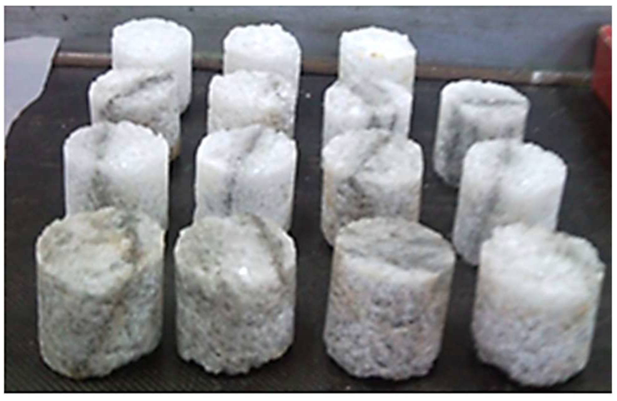
Figure 2.
Rooms and rectangular pillars exploitation system.

Figure 3.
Small rooms and square pillars exploitation system.
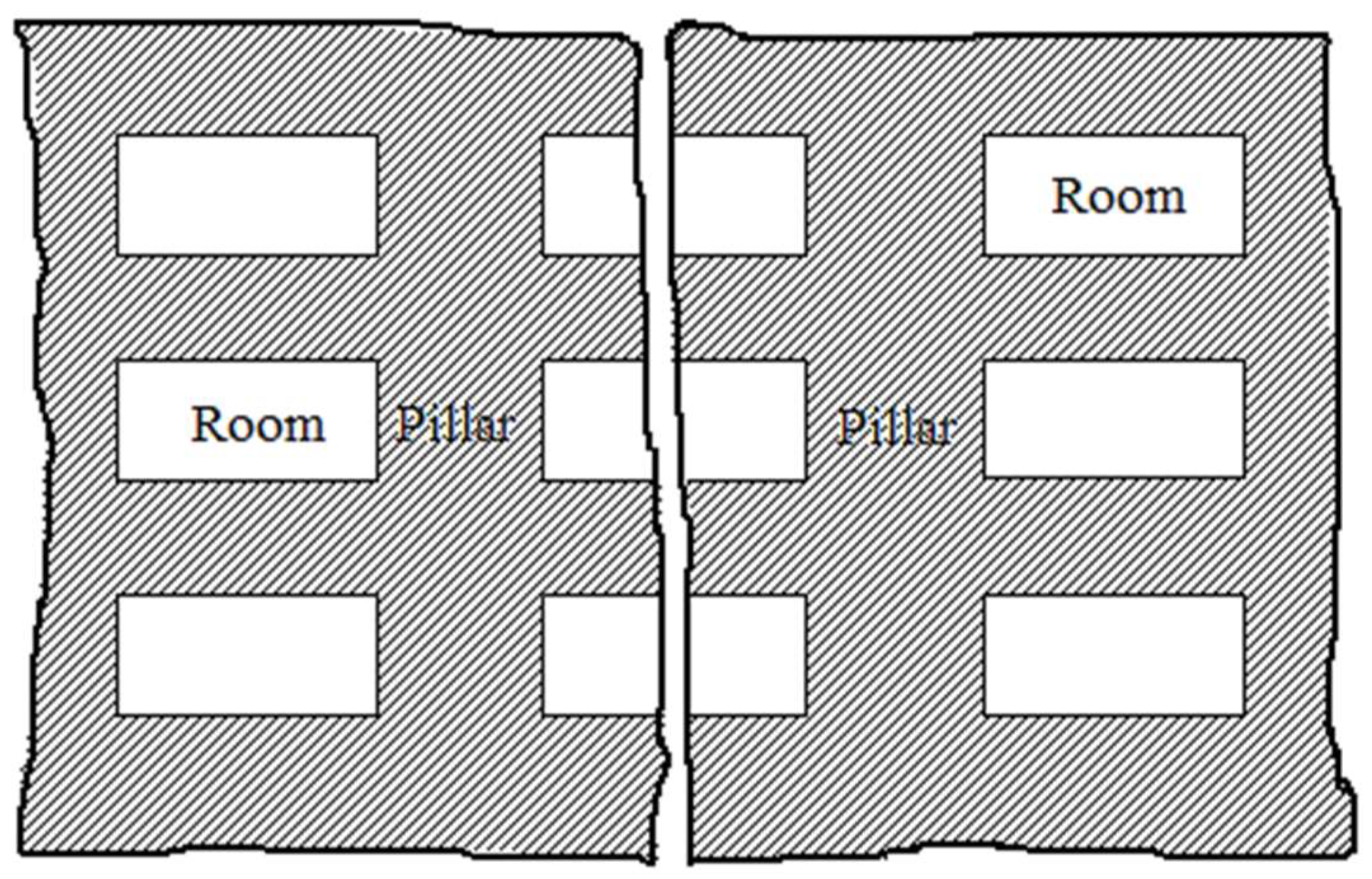
Figure 4.
Quantitative evaluation of the secondary stress state through the operating system with small rooms and rectangular pillars.
Figure 4.
Quantitative evaluation of the secondary stress state through the operating system with small rooms and rectangular pillars.

Figure 5.
Stability evaluation of the operating system according to the equilibrium principle limits: (a) the variation in the effective stress; (b) the variation in load degree; (c) the deformation variation over a period of 100 days.
Figure 5.
Stability evaluation of the operating system according to the equilibrium principle limits: (a) the variation in the effective stress; (b) the variation in load degree; (c) the deformation variation over a period of 100 days.

Figure 6.
Extraction coefficient variation (a) and load degree variation (b) depend on depth H0 and room–pillar geometry (Hmax = 500 m).
Figure 6.
Extraction coefficient variation (a) and load degree variation (b) depend on depth H0 and room–pillar geometry (Hmax = 500 m).

Figure 7.
The variation in the effective stress and the limit stress (a), the extraction coefficient (b), and the load degree (c) depends on the operating depth H0 and the geometry of the room and pillar (Hmax = 800 m).
Figure 7.
The variation in the effective stress and the limit stress (a), the extraction coefficient (b), and the load degree (c) depends on the operating depth H0 and the geometry of the room and pillar (Hmax = 800 m).

Figure 8.
Schema of the location points where the components of the secondary stress state were calculated.
Figure 8.
Schema of the location points where the components of the secondary stress state were calculated.
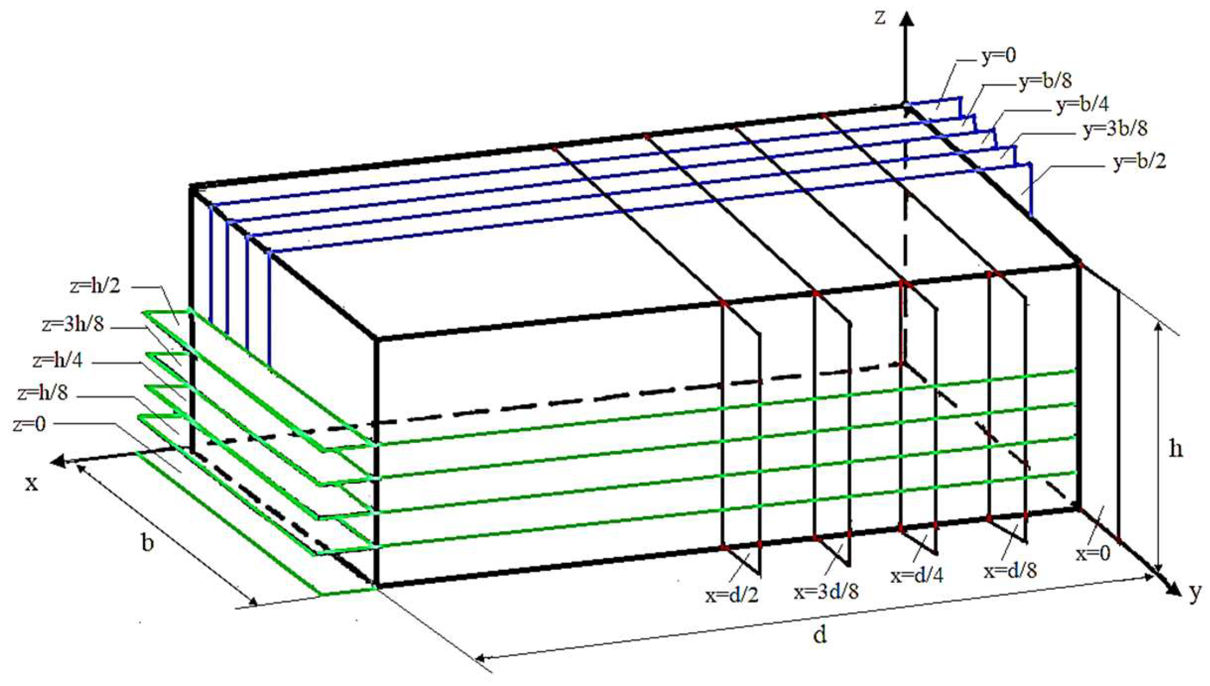
Figure 9.
The spatial distribution of the vertical component of the secondary stress state.
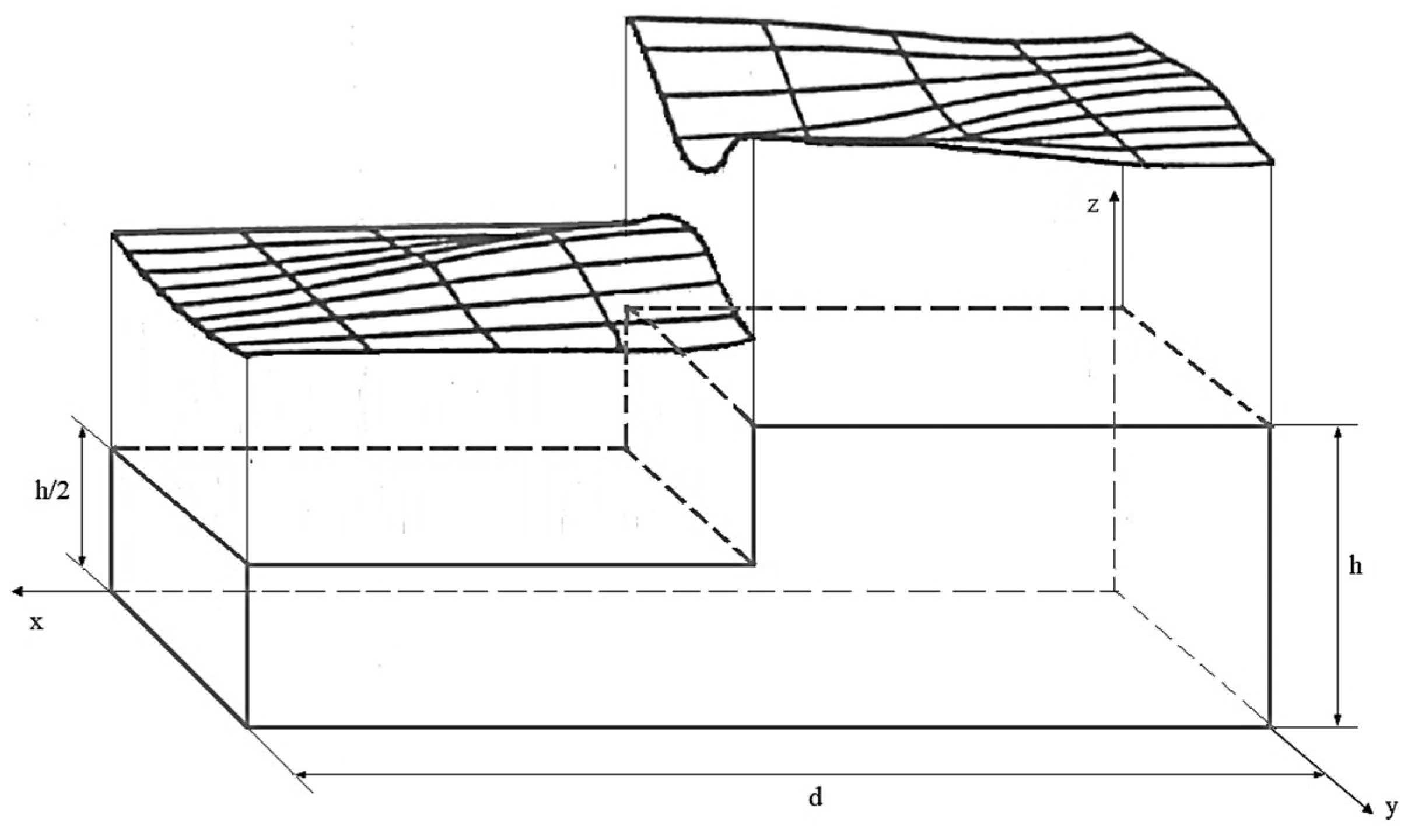
Figure 10.
The axial component of the secondary stress state in the pillar at a depth of 100 m.

Table 1.
Coefficients A0, B0, and C0 for different values of the pillar’s slenderness.
| λ = h/b | Coefficient | Ration h/Day | |||||
|---|---|---|---|---|---|---|---|
| 0.01 | 0.2 | 0.4 | 0.6 | 0.8 | 1.0 | ||
| 0.1 | A0 | −21.31 | −25.76 | −24.64 | −23.44 | −22.61 | −22.07 |
| B0 | −28.40 | −20.14 | −13.71 | −8.94 | −5.81 | −3.85 | |
| C0 | −220.91 | 46.09 | 12.49 | 5.68 | 3.23 | 2.09 | |
| 0.5 | A0 | −11.13 | −10.99 | −10.46 | −9.89 | −9.55 | −9.38 |
| B0 | −25.48 | −20.41 | −12.92 | −8.00 | −5.04 | −3.25 | |
| C0 | 8.88 | 6.26 | 2.93 | 1.48 | 0.93 | 0.66 | |
| 1 | A0 | −3.90 | −3.71 | 3.39 | −3.13 | −2.96 | −2.86 |
| B0 | −23.29 | −19.02 | −12.08 | −7.29 | −4.50 | −2.86 | |
| C0 | 2.23 | 1.74 | 0.95 | 0.46 | 0.22 | 0.12 | |
| 2 | A0 | −0.74 | −0.67 | −0.55 | −0.46 | −0.42 | −0.40 |
| B0 | −22.25 | −18.40 | −11.89 | −7.21 | −4.43 | −2.81 | |
| C0 | 0.56 | 0.46 | 0.28 | 0.16 | 0.09 | 0.05 | |
| 3 | A0 | −0.24 | −0.20 | −0.14 | −0.10 | −0.08 | −0.07 |
| B0 | −22.05 | −18.30 | −11.91 | −7.28 | −4.50 | −87 | |
| C0 | 0.25 | 0.21 | 0.13 | 0.08 | 0.05 | 0.03 | |
Table 2.
Input data.
| Pillar Width (m) | Pillar Height (m) | Apparent Specific Weight, γa × 104 (N/m3) | Depth H, (m) | Elasticity Modulus of the Salt, E (MPa) | Poisson’s Coefficient, μ |
|---|---|---|---|---|---|
| 14 | 8 | 2.2 | 100 | 726 | 0.25 |
Disclaimer/Publisher’s Note: The statements, opinions and data contained in all publications are solely those of the individual author(s) and contributor(s) and not of MDPI and/or the editor(s). MDPI and/or the editor(s) disclaim responsibility for any injury to people or property resulting from any ideas, methods, instructions or products referred to in the content. |
© 2024 by the author. Licensee MDPI, Basel, Switzerland. This article is an open access article distributed under the terms and conditions of the Creative Commons Attribution (CC BY) license (https://creativecommons.org/licenses/by/4.0/).
Share and Cite
MDPI and ACS Style
Toderas, M. Stability Analysis of the Exploitation System with Room and Pillar by Analytical Methods. Appl. Sci. 2024, 14, 1827. https://doi.org/10.3390/app14051827
AMA Style
Toderas M. Stability Analysis of the Exploitation System with Room and Pillar by Analytical Methods. Applied Sciences. 2024; 14(5):1827. https://doi.org/10.3390/app14051827
Chicago/Turabian StyleToderas, Mihaela. 2024. "Stability Analysis of the Exploitation System with Room and Pillar by Analytical Methods" Applied Sciences 14, no. 5: 1827. https://doi.org/10.3390/app14051827
Note that from the first issue of 2016, this journal uses article numbers instead of page numbers. See further details here.